nureg/cr-4597, 'aging and service wear of auxiliary ... · pumps and are basically small...
TRANSCRIPT

Ez E.?
NUREG /CR-4597Volume 1ORNL-6282/V1
RV'OAK RIDGENATIONALLABORATORY
Aging and Service Wear of AuxiliaryFeedwater-Pumps for PWR
Nuclear Power PlantsA a
V.I
f '.
I
I r
I'
Volume 1. Operating Experienceand Failure Identification
M. L. AdamsE. Makay
208 LIBRARYOCT 13 1986
REACTOR SAFElY andWork Per-forM~tE HSC
U.S. Nuclear Regulat r o missionOffice of Nuclear Regulatory Research
Under DOE Interagency Agreement No. 40-551-75NRC FIN No. B0828
OPERATED BYMARTIN MARIETTA ENERGY SYSTEMS; INC.FOR THE UNITED STATESDEPARTMENT OF ENERGY

NOTICE
This report was prepared as an account of work sponsored by anagency of the United States Government. Neither the UnitedStates Government nor any agency thereof, or any of theiremployees, makes any warranty, expressed or implied, orassumes any legal liability or responsibility for any third party'suse, or the results of such use, of any information, apparatusproduct or process disclosed in this report, or represents that itsuse by such third party would not infringe privately ownedrights.
Available from
Superintendent of DocumentsU.S. Government Printing Office
Post Office Box 37082Washington, D.C. 20013-7982
and
National Technical Information ServiceSpringfield, VA 22161
NUREG/CR-4597Volume 1ORNL-6282/VlDist. Category RV
AGING AND SERVICE WEAR OF AUXILIARY FEEDWATER PUMPSFOR PWR NUCLEAR POWER PLANTS
Volume 1. Operating Experience andFailure Identification
M. L. Adams E. Makay
Manuscript Completed - June 24, 1986Date Published - July 1986
Report Prepared byEnergy Research and Consultants Corporation
900 Overton AvenueMorrisville, Pennsylvania 19067
underPurchase Order No. 1IX-28630V
for Oak Ridge National Laboratory
Work Performed forU.S. Nuclear Regulatory Commission
underDOE Interagency Agreement No. 40-551-75
NRC FIN No. B0828
OAK RIDGE NATIONAL LABORATORYOak Ridge, Tennessee 37831
operated byMARTIN MARIETTA ENERGY SYSTEMS, INC.
for theU.S. DEPARTMENT OF ENERGY
under Contract No. DE-AC05-840R21400

iii
CONTENTS
Page
LIST OF FIGURES .......... ... ... ... ........... *.*. * ** **** ....... vii
LIST OF TABLES ...................................... ... ix
ACKNOWLEDGMENTS ...................... xi
SUMMARY ProjectiScopei....i..... .. ....... ... ..... .. ...... .. .. .*.. xiii
ABSTRACT Definitions... ... .... ... *.* * * *** * ** ***** ...... 1
1. INTRODUCTION . ..................... .1... .. ............ ..... . 41.1 Background .......T.of ..AuFeedwater.Pumps................ 1
1.2 Project Scope undaries2...*............*........*.. 2
1.3 Definitions .......Reur t 3.. . .. .. . .. . .. . .. .. . . .. .. . .. . .. .. 82. BACKGROUND INFORMATION ......... ............................. 4
2.1 Principal Types of-,Auxiliary Feedwater Pumps ................................... 4
2.2 Equipment Boundaries ................................... 7
2.3 Functional Requirements ... ooo................o................00..0 8
2.3.1 General requirements o*. oo**oe............................. oo#*........ 82.3.2 Seismic requirements *.............................. 82.3.3 Miscellaneous *.. . .............................. .. 8
2.4 Materials of-Construtction ....* ......................... 8
3. TECHNICAL SPECIFICATION REQUIREMENTS ... ..................... 10
4. SUMMARY OF OPERATING CONDITIONS AND STRESSOR INFLUENCES ... o.. 11
4.1 Description of Typical Operating Regimes ................ . 11
4.1.1 Regimes ... ...................................... 114.1.2 Pump operating information for each regime ...... 114.1.3 Pump external environment ... ......................... 12
4.2 Stressor Description .... ............. *...........**..... 12
4.2.1 Mechanical .... oo... .... *oo................ .... 124.2.2 Hydraulic oo..................................................... 12.4.2.3 Tribologicalo oo.o..oo.o.o.o..oo.o.o.o............................. 134.2.4 Chemical ....... 00.. . 0*.000*... ...... .......................... 134.2.5 Low-relevance factors .....ooo.....o...ooo......... 13
4.3' Stres-sor-Influeonce o..............o................'ooooooo .o.o.o.o.ooo.. 13
4.3.1 Pump parts and components ...o ... o-ooo.ooo...... 134.3.2 Operating 'regimes .. .. .o.o..o.. o...............o.o ... . 18

iv
Page
5. OPERATING EXPERIENCE .. ......... 24
5.1 Failure Modes and Failure Causes .. ..................... 24
5.2 Frequency of Failure ................. .................. 26
5.3 Methods of Detection ............................ ....... 26
5.4 Maintenance Action .. ................................... 26
5.5 Modifications Resulting from Failures .................. 26
6. FAILURE MODES AND FAILURE CAUSES ............... o.............. 27
6.1 Failure Modes .......................................... 27
6.1.1 Failure to operate * ...... .. ... 276.1.2 Failure to operate as required .................. 276.1.3 External leakage ............ ............ .. .... 28
6.2 Failure Causes . .......... . .o. .. ..... . ................. . 28
6.2.1 Causes of failure to operate .......... ............ 286.2.2 Causes of failure to operate as required ........ 306.2.3 Causes of external leakage .... .................. 31
6.3 Failure Cause Analysis .................. ............... 32
6.3.1 Large hydraulic forces and vibarations createdby pump hydraulics .......... ........ . . . . . . . . . . . . . . 32
6.3.2 Shaft breakage .*..o.. ......... .. . . ............... 33 £6.3.3 Impeller and diffuser breakage .................. 346.3.4 Thrust bearing and thrust balancer failures ..... 346.3.5 Coupling breakage ........ . . . ........ .... *.O. ... .. . . . .. 346.3.6 Seizure ......... ........................... . . . 35
7. RECOMMENDED MAINTENANCE, SURVEILLANCE, AND MONITORINGPRACTICES .... ; .............. so ............................. 36
7.1. Regular Maintenance . ... ..... ............ ... ... . 36
7.2. Surveillance s...................... o.............. * ... *o........... 37
7.2.1 Current surveillance practice andlimitations ........... 000..oo.................................. 37
7.2.2 Interim recommendations for surveillance andmonitoring practices ......... ................... 37
7.2.3 Interim recommendations for detailedinspection program . .......... .... .......... . . . . . . ... .. 38
8. AGING AND SERVICE WEAR MONITORING ........................... 39
8.1 Monitoring of Present Configurations ................... 39
8.1.1 Rotor binding check ........... ....... . . ...... 39
8.1.2 Shaft seal leak-off flow ........................ 39 £
8.1.3 Disassembly'and detailed inspection ..... so ...... 40
.1

v
8.2 Continuous Parameter Monitoring ......................
8.2.1 Rotor vibration monitoring ...................8.2.2 Bearing temperatures and noises ................8.2.3 Rotor axial position ...........................8.2.4 Pump head-capacity curve .... . . .
8.3 Summary of Aging and Service Wear Factors .............
9. SUMMARY AND RECOMMENDATIONS .............. ...... .s.. ..... ...
9.1 Summary ................................
9.1.1 Bypass flow criteria .........................9.1.2 Secondary bypass flow test loop .....9.1.3 Monitoring and establishing trends ............9.1.4 Scheduled disassembly and detailed t'
inspections so ....... .... . ... . .....9.1.5 Pump specifications ..... . ...... .......
9.2 Recommendations .... .o. . ........ . .......
REFERENCES ....... ...O ...........I ..R ....AP ............E C ....E
BIBLIOGRAPHY ...................... *....................
APPENDIX A. SUMMARY OF ASME BOILER AND PRESSURE VESSEL CODE
Page
43
43444444
45
51
51
515152
5252
52
54
55
59
63
67
APPENDIX
APPENDIX
APPENDIX
B.
C.
D.
SECT. XI REQUIREMENTS ..............................
OPERATING EXPERIENCE DATA BASES AND REPORTS ........
AUTOMATIC TRIPPING AND FAILURE ..................
ENGINEERING INFORMATION RELEVANT TO AUXFPRELIABILITY ...................... a........... ....... 69

vii
LIST OF FIGURES
Figure Page
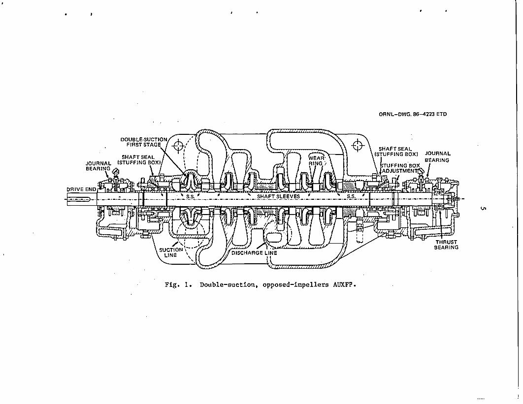
1 Double-suction, opposed-impellers AUXFP ................ 5
2 Single-suction, opposed-impellers AUXFP ......... ** ..... 6
3 Single-suction, in-line-impellers AUXFP ................ 6
4 NPAR program strategy .* ...... . .. .. .. ... ................ e .... 53
D.1 Anticipated useful operating ranges for pumps usedin large nuclear and fossil power generating units 70
D.2 Formation of stall (a) in diffuser and (b) in eyeof impeller .... *..o .. * .*.. e..*.... 71
D.3 Secondary flow pattern in and around pump impellerstage at off-design flow operation ..................... 72
D.4 Head-capacity characteristics of multistage boilerfeed pumps . . .... ... ... . . .. .. ..*. .. * ..... 73
D.5 Influence of pump impeller to diffuser/volute radialgap on pressure pulsation at blade-passing frequencyand rotor deflection caused radial forces 74
D.6 Frequencies of hydraulically induced dynamic forcesacting on the rotor of a centrifugal pump ....... * ... 76
D.7 Vibration frequency vs speed .......... ................. 77
D.8 Allowable rotor vibration levels measured relativeto the bearing cap ... . ... ..... so......... 78
D.9 Customary axial balancing devices for high-pressuremultistage boiler feed pumps ........................... 81
D.10 Parallel and tapered face balance disk designs ......... 82
D.11 Shaft seal types used in boiler feed, nuclearfeed, and feedwater booster pumps ...................... 84
D.12 Typical AUXFP bearing system ...... ..................... 85
D.13 Typical multistage centrifugal pump shaft failurelocations ........................................ 86

ix
LIST OF TABLES
Table Page
1 Examples of typical AUXFP BEP operating parameters ...... 12
2 Stressor influence on rotating elements .................. 19
3 Stressor influence on nonrotating internals ............. 20
4 Stressor influence on pressure-containment casing ....... 21
5 Stressor influence on mechanical subsystems ............. 22
6 Stressor influence on support ... *.................. ... 23
7 Summary of AUXFP pump failure information available fromoperating experience and plant documents .....*........... 25
8 Failure modes ..... .... .. .. . ... . ... 0. .. ...... *.... ...-*....*. 28
9 Summary of failure modes and causes .... .... ............. 29
10 Pump failure causes related to aging and servicewear o.....oo.ooooooooooo...oo.ooo..oo.oo.. o.oo............... 45
11 Methods currently used to detect AUXFP failure modes .... 46
12 Methods for differentiating between failure causes ...... 47
13 Measurable parameters ......... o...................... .o.o. 49
14 Summary of important AUXFP part failure assessment ...... 50
B.1 Summary of AUXFP-type failures reported in LERs(1973-1983) ......... 0....................... 0.. ..0.0.0........ .. 64
B.2 AUXFP-type failures reported in NPRDS data base(1974-1985) ..p.lrea .... d.a.astudy.. . .... .. o...o......... 65
B.3 In-plant reliability data study ...................... .o.o.o................ 66
xi
ACKNOWLEDGMENTS
The authors gratefully acknowledge the continuing support and coun-sel of the Nuclear Regulatory Commission Nuclear Plant Aging ResearchProgram manager, J. P. Vora, in the planning and implementing of thisstudy. W. L. Greenstreet of Oak Ridge National Laboratory directed thework on this report, which was substantially configured through hisdirection and advice.
The information, insights, conclusions, and recommendations con-tained in this document are based primarily on the design, trouble-shooting, and redesign experience of Energy Research and ConsultantsCorporation in power plants for electric utility companies. The authorsgratefully acknowledge the cooperation of several Electric Utility Com-panies, in particular, operating personnel at the Palo Verde nuclearplant of Arizona Public Service Company.
In addition, we wish to express our thanks to the following pumpmanufacturers for their openness ~in discussing their points of view:-Ingersoll-Rand, Byron Jackson;--Pacific-Pump Division of Dresser Clark,and Bingham Pump Companies.
xiii
SUMMARY
The primary focus of this report is on factors that are important toaging and service wear of auxiliary feedwater pumps (AUXFPs). Thesepumps are from the generic family of-multistage high-head centrifugalpumps and are basically small boiler feed pump designs used in smallcapacity, mostly older fossil fuel electric generating plants.
A general description of AUXFPs is provided and includes illustra-tions, construction and configuration details, defined equipment bound-aries, functional requirements, and materials of construction. Technicalspecification requirements and operating experience topics are summar-ized. Operational stressors are categorized, and a detailed stressorlist is provided, component-by-component.
Failure modes are defined as follows: O(1) failure to-operate,(2) failure to operate as required,--and (3) external leakage. Failurecauses are identified in general terms and subsequently described in morespecific terms in a section on failure cause analysis. The single most'important-factor-relevant-t6-AUXFP potential failures is the presence 6flarge hydraulic dynamic forces'within such pumps, particularly at flow'rates substantially different -than the best-efficiency flow. Correspond-ingly, determining safe minimum AUXFP flow rates (i.e., bypass or recir-culation flow) is a very important task. This topic is discussed atlength in Sect. 6 and in Appendix D.
Methods for detecting failure modes and differentiating betweenfailure causes are described. In addition, measurable parameters (in-cluding functional indicators) are identified for potential use in de-tecting and monitoring degradation and for tracking degradation trends.
Parameters for identifying failure causes of pumps include
Vibration ClearanceDelivered flow Rotor axial positionRotational speed Leakage rateBearing temperature AppearanceTransmitted torque Local shaft temperatureNoise Bolt torque
The appropriateness and utility of these and other parameters will beaddressed in subsequent phases of the AUXFP investigation.
At present, most AUXFP installations contain no monitoring.devicesexcept for flow and head measurement, in contrast to continuously running
.power plant equipment. Furthermore, present surveillance practice con-sists primarily of starting each AUXFP at bypass flow once every 1 to 3months for a short-duration test to verify operational readiness. Thus,the establishment and correlation of AUXFP operating parameters (e.g.,vibration and bearing temperatures) to wear and aging criteria are notaddressed in nearly all installations as presently configured and instru-mented. Actions are detailed to address these present weaknesses. Theseactions include (1) disassembly and inspection and component renewal atrefueling intervals and (2) parameter monitoring and instrumentationretrofits. These and other important factors are addressed in Sect. 9.
xiv
Appendix D provides a major background section on engineering in-formation and design factors critically important to AUXFP reliability.The Bibliography contains an extensive list of over 40 publications andreports, which have been prioritized to aid in selecting those that aremost critical to understanding the potential operating problems and fail-ure modes of AUXFPs.
AGING AND SERVICE WEAR OF AUXILIARY FEEDWATER PUMPSFOR PWR NUCLEAR POWER PLANTS
Volume 1. Operating Experience andFailure Identification
M. L. Adams* E. Makay*
ABSTRACT
This rep6rt was produced under the Detection of Defects andDegradation Monitoring element of the Nuclear Plant Aging Re-search Program. Typical auxiliary feedwater pump (AUXFP) con-figurations are described in terms of configuration details,materials of construction, operating requirements, and modesof operation. AUXFP failure modes and causes due to aging andservice wear are identified and explained, and measurableparameters (including functional indicators) for potential usein assessing operational readiness, establishing degradationtrends, and detecting incipient failures are given.
A series of measures to correct present deficiencies insurveillance, monitoring, and in-service testing practices isdiscussed. The main body of the report is supplemented by anumber of relevant appendixes; in particular, a major appendixis included on engineering and design information useful toassess AUXFP operational readiness.
1. INTRODUCTION
1.1 Background
The Office of Nuclear Regulatory Research of the Nuclear RegulatoryCommission (NRC) has instituted studies aimed at understanding the time-related degradation (aging) of nuclear power plant systems and equipment,assessing the effectiveness of methods of inspection and surveillance tomonitor such degradation, and establishing guidelines for maintenance.This study is one in a series intended to provide technical bases toassess the ongoing operational safety of operating plants. The strategyfollowed can be used by others interested in analyses of equipment innuclear applications.
This report addresses time-related degradation of pressurized-waterreactor (PWR) power plant auxiliary feedwater pumps (AUXFPs). fBecausefailures of these components can reduce-the amount of feedwatereavailable
*Energy Research and Consultants Corporation, 900 Overton Avenue,Morrisville, Pa. 19067.
2
for removing heat when the usual feedwater supply is unavailable, suchfailures can result in altered safety margins for PWR systems.
1.2 Project Scope
This report is Volume 1 of a three-part report to be prepared onAUXFPs. The contents of the three volumes are summarized below.
Volume 1 - Operating experience and failure identification (Phase 1)
1. Background information on AUXFPs - boundary of A1JXFPs to be studied,types, functional requirements, and materials of construction;
2. Reviews of regulatory requirements, guides, and standards;3. Summary of operational and environmental stressors;4. Summary of operating experience;5. Manufacturers' input; and6. State-of-the-art aging and service wear monitoring and assessment.
Volume 2 - Aging assessments and evaluation of monitoring methods(Phase 2)
1. Results from completion of comprehensive aging assessment based onpostservice examination and tests of aged components and in-situassessments,
2. Identification of monitoring techniques and review of informationproduced, and
3. Evaluations of monitoring methods.
Volume 3 - Analysis and recommendations
1. Value impact analysis, and2. Recommendations for guidelines for monitoring methods and mainte-
nance.
One of the objectives of the Phase 1 research effort is to providebaseline information for use in subsequent phases of the study. To pre-pare this report, operating experience, manufacturers' information, andinformation derived from design, troubleshooting, and redesign experiencewere reviewed to identify (1) failure modes and causes resulting fromaging and service wear of AUXFPs and (2) measurable parameters (includingfunctional indicators) with potential for quantifying and tracking degra-dation. These parameters are to be applicable for detecting and estab-lishing time-dependent degradation trends before loss of function.
3
1.3 Definitions
For the purpose of this report, the following definitions apply.Failure mode - the way a component does not perform a function for
which it was designed (e.g., fails to actuate or leaks to outside).Failure cause - degradation (the presence of a defect) in a compo-
nent that is the proximate cause of its failure (e.g., bent shaft, lossof lubricant, or loosening of a bolt).
Failure mechanisms - the phenomena that are responsible for thedegradation present in a given component at a given time. Frequently,several failure mechanisms are collectively responsible for degradation(synergistic influences). One major failure mechanism, where identified,has been called the "root cause." Generic examples of failure mechanisms(and of root causes) include aging, human error, or seismic events.
Aging - the combined cumulative effects over time of internal andexternal stressors acting on a component, leading to degradation of thecomponent, which increases with time. Aging degradation may involvechanges in chemical, physical, electrical, or metallurgical properties,dimensions, and/or relative positions of individual parts.
Normal aging - aging of a component that has been designed, fab-ricated, installed, operated, and maintained in accordance with specifi-cations, instructions, and good practice and that results from exposureto normal stressors for the specific application. Normal aging should betaken into account in component design and specification.
Measurable parameters - physical or chemical characteristics of acomponent that can be described or measured directly or indirectly andthat can be correlated with aging. Useful measurable parameters arethose that (1) can be used to establish trends of the magnitude of agingassociated with each failure cause, (2) have well-defined criteria forquantifying the approach to failure, and (3) are able to discriminatebetween the degradation that leads to failure and other observed changes.
Inspection, surveillance, and condition monitoring (ISCM) - thespectrum of methods and hardware for obtaining qualitative or quantita-tive values of a measurable parameter of a component. The methods may beperiodic or continuous, may be in-situ, or may require removal and in-stallation in a test stand or disassembly and may involve dynamic orstatic measurements.
4
2. BACKGROUND INFORMATION
2.1 Principal Types of Auxiliary Feedwater Pumps
AUXFPs for PWR systems are basically small boiler feed pumps used insmall-capacity mostly older, fossil fuel electric generating plants.Thus, they retain most of the design features, plus the potential operat-ing and reliability problems inherent in the feedwater pumps. A compre-hensive bibliography of publications and reports document extensive fieldtroubleshooting experience and analyses that are most relevant to AUXFPmachinery. This bibliography also represents the several years ofexperience upon which the contents of the report rest.
AUXFP configurations are all multistage (from 6 to 12) with low-specific-speed, high head-per-stage (HHPS) impellers, having either vane-diffuser or volute collection chambers at the discharge section of eachstage. The overall construction is always an axially (horizontal) splitouter casing with internal stage-to-stage connecting flow passages (seeFigs. 1-3).
More specific details of configuration vary considerably from vendorto vendor. Even within the array of available designs from a singlemanufacturer, there can be a considerable variety of construction de-tails. The main factor that determines these more specific configurationdetails is the design approach used in handling the very large axialthrust forces on the rotor, which arise as a natural by-product in HHPScentrifugal pumps. A second factor is the design approach used to avoidcavitation in the inlet (suction), that is, single-suction (Figs. 2 and3) or double-suction (Fig. 1) inlet stage.
Some manufacturers use a configuration with all stages positioned inthe same axial direction (Fig. 3, called "in-line" type). Other manufac-turers use a configuration with the stages on one-half of the shaftaxially opposed to those on the other half of the shaft (Figs. 1 and 2,called "opposed" type) for thrust cancellation. The basic differencebetween these two configurations involves the previously referenced dif-ferent design approaches to handling the very large axial thrust loadsinherent in multistage HHPS centrifugal pumps. Opposed type configura-tions (i.e., thrust cancellation approach) are often designed with only athrust bearing. In-line type configurations are always designed with anadditional thrust balancer of either "balancing drum" type or "balancingdisk" type (see Appendix D).
Plants have traditionally been configured with two AUXFPs perpressurized-water reactor (PWR). In most plants, one AUXFP is steam tur-bine driven, and the other is electric motor driven. The steam-turbine-driven unit has the advantage of variable speed, and the maximum designoperating speeds are generally in the 4000- to 5000-rpm range. Themotor-driven unit is usually designed for two-pole induction motor speedand powered from either one of two standby diesel-driven generators.Newer plants may also have a third "backup" AUXFP that is electric motordriven either from main line power or switchable to the diesel-drivengenerator bus. Thus, to provide very high standby reliability of theAUXFP system, the number of pumps employed (now three) and the number of
ORNL-DWG. 86-4223 ETD
DOUBLE SUCTIONFIRST STAGE /p\\
* s/ SVW A.. \E 9 \ ................. SHAFTSEALSTUFFING BOX) JOURNAL
JOURNAL (STUFFING BOX) RTFNGBO BEARINGBEARING ADUIMNG Bo
DRIVE END I 14
| I > s S.S. # # >SHAFT SLEEVES i f S.S. ... ........ . ............................... .. ....... ......t\W~~~~~~~~~~~iiA- - - -- - - ---- ---_ =4w
Fig. 1. Double-suction, opposed-impellers AUXFP.

6
ORNL-DWG. 86-4224 ETO
Fig. 2. Single-suction, opposed-impellers AUXFP.
ORNL-DWG. 86-4225 ETD
SUCTION
I
THRUSTBALANCER
Fig. 3. Single-suction, in-line-impellers AUXFP.
7
separate power sources (i.e., steam, diesel-generator, main line) aretriple redundant. The overall-approach that now is emerging in the new-est plants is to have-the backup AUXFP be a non-safety-related, non-nuclear class (nonclass). pump.(thus cheaper) and to use it for all normalplant startup, shutdown, and nonemergency service. However, the PlantTechnical Specification requires readiness testing of nuclear class(N-class) AUXFPs at least every 3 months.
The rated discharge pressure for nuclear plant AUXFPs ranges from1100 to 1500 psig. The rated capacity ranges from 200 to 1000 gal/min.However, rated head and capacity are generally pegged to the best-efficiency-point (BEP) flow at a given speed, and AUXFPs are required tooperate over a wide range of percent BEP flow. They are typically re-quired to operate from 10 to 140%-of--BEP capacity. Thi s-is considered arather abusive operating requirement from the point of view of acceptablepractice for main feedwater pumps.
2.2 Equipment Boundaries
For present purposes,-the-primary focus is on-the pump per se, thedrivers being outside the scope of this report. However, it is appropri-ate to give consideration to defining-a-'system, that is, equipment bound-aries.
The pump is mechanically coupled to its driver (steam turbine orelectric motor). The pump-driver assembly is typically mounted on a com-mon fabricated steel base 'that is stiffly connected to some structural"floor" section within the plant. Furthermore, the pump is hydraulicallyand mechanically connected to a fluid flow circuit through its inlet(suction) and discharge nozzles. For a turbine-driven pump, the turbineinlet is, of course, piped into a steam flow circuit and the outlet to acondenser. For a motor-driven pump, the motor is electrically connectedto a 60-Hz, 3-phase power supply. Thus,' the equipment boundaries will betaken to include the driver and pump on a common base and with the bound-ary taken to include all inlet and discharge nozzles as well as directelectrical connections. However, aging, wear, and failures of the driverand connecting steam or electrical power lines are not addressed in thisreport.
Failures outside this defined boundary will also not be consideredin this report. The small steam turbines and the electric motors used todrive AUXFPs are standard designs used in many other applications as welland as yet do not appear to exhibit any aging'or wear factors that areunique to the AUXFP application. Based on operating experience on simi-lar pumping systems for other applications, driver failure can be causedby a massive failure of the pump. Primarily, this would be a pump fail-ure resulting in loss of thrust balancer-and thrust bearing load-carryingcapacity. In such a situation,-depending upon the specific- pump andcoupling design,-there is a potential for subjecting the driver (i.e.,its thrust bearing) to dadmaging-load-levels. Excessive pump vibration isanother factor that could accelerate wear and aging of the turbine ormotor driver.
8
2.3 Functional Requirements
AUXFP functional requirements may vary somewhat from plant to plantand also vary as a function of plant vintage. The following itemizationof functional requirements includes the typical ranges for quantifiableparameters where appropriate.
2.3.1 General requirements
1. Supply feedwater to the steam generators under plant startup, normalshutdown, hot standby, and emergency conditions;
2. meet automatic starting requirements;3. operate under normal and accident conditions of temperature, pres-
sure, humidity, radiation, and available net positive suction head(UPSH); and
4. withstand seismic loadings without loss of function.
2.3.2 Specific requirements
1. Capable of producing the rated flow against the rated head within20 s (typical) after actuation,
2. total of 1000 service-life operating cycles [includes all items in2.3.1 (1)],
3. AUXFP operating cycle including up to 10 h of continuous pumping,4. operation of pump at shutoff (upset condition) for up to 10 min,5. a plant life of 40 years,6. a steadily rising head-capacity characteristic with a shutoff head in
the range of 115 to 130% of best-efficiency head at a given speed,7. an efficiency characteristic commensurate with state-of-the-art
hydraulic design, and8. capable of operating at any point on the head-capacity curve, from
minimum flow to full run-out condition (i.e., maximum pump flowpossible against system resistance) during and following safe reactorshutdown at earthquake condition.
2.3.3 Miscellaneous
1. To be available for operation, except when taken off-line for main-tenance or testing, and
2. to be supplied with appropriate protective devices such as overspeedtrip.
2.4 Materials of Construction
Precise material designations vary somewhat from vendor to vendor.Also, in a number of AUXFP components, the current material or method offorming may not be the optimum for this application. The primary reasonfor this is that purchaser specifications are not always optimally expli-cit, potentially resulting in competing vendors using lower cost options.

Thus, the following ''arag-hs''l'oit-only summarize-current- practice butalso contain suggested alternatives that should be studied.
The two parts of the split casing, including inlet and dischargenozzles, are made of a cast carbon or stainless steel. The most commonis the cast equivalent of 416 stainless steel, designated when cast asCA6NM.
The shaft is currently machined from'400-series'stainless steel barstock by all vendors. Typical material designations are 410, 414, and416 stainless steel. A more durable alternative for consideration is tomake the shaft from a forging.
Impellers are made of high-chromium alloy steels and are sand castby all vendors. Commonly used alloys are 13-5 (i.e., 13% Cr, 5% Ni),15-5, and 17-4 Ph. Here again, current practice may not have been opti-mally constrained by purchaser specifications. That is, impellers couldbe specified as precision cast to provide maximum quality both in termsof structural integrity and dimensional control of critical hydraulicpassages.
The diffusers and stage-to-stage return channel components are alsosand cast with the material varying from vendor to vendor, for example,stainless steel 440A, 440B, and 17-4 Ph. As in'the case of the impel-lers, optimum dimensional control of critical hydraulic passages suggeststhat precision cast or milled diffusers and return channels should beconsidered.
The coupling (used to connect pump to driver) materials vary con-siderably with coupling type and manufacturer. The type of coupling usedin nearly all installations is the gear type. However, tooth clearancesin such couplings, always produce some measurable rotor unbalance that, isnot correctable. Furthermore, lubrication is required to prevent wearoutin service. For these reasons, the dry flexible diaphragm type of coup-ling should be considered.
The main pressure-closure retaining bolts (studs) are made of hightensile strength Cr-Mo steels, suitable for the high prestressing neces-sary to ensure a leaktight and structurally sound closure at the casingjoint.
Various shaft sleeves are made of the same steel alloys as theshaft. Shaft-sleeve retaining bolts are also made of similar steelalloys as the shaft.
Balancing disks, balancing drums, and wear rings are typicallymachined from stainless steel alloy material such as 416 and 420. Aconsiderable enhancement to reliability can be ensured if the material isdesignated as 420F, which is a "free machining nongalling' stainlesssteel with a trace of phosphorus (0.17%) or sulfur (0.3%).
Oil-film journal bearings and thrust bearings are typically con-structed of carbon steel shells with bearing surfaces lined with babbittwhite metal (usually tin base for best results) that is cast into thepreheated bearing shell and finished machined to the specified finaldimensions. Rolling contact bearings, which are available to take radialand axial loads, are constructed of various specialty steels.typicallyused in such bearings. These bearings are case hardened to rprovide veryhigh strength outer (surface) properties and a more ductile inner core ofthe rolling contact elements. _
10
3. TECHNICAL SPECIFICATION REQUIREMENTS
Testing requirements for AUXFPs in nuclear power plants are de-scribed in the plant Technical Specifications that state the overall in-service inspection requirements for safety-related systems and components.In-service inspection and testing of ASME Class 1, 2, and 3 componentsare to be in accordance with Sect. XI of the ASME Boiler and PressureVessel Code.
The Sect. XI testing requirements for pumps involve measuring inletpressure, pressure differential across the pump, flow rate, and vibrationamplitude; all are measured while operating at specific design conditions.The test quantities are compared with reference values.
The ASME Code Sect. XI contains surveillance intervals, frequencies,and test requirements for Code Class 1, 2, and 3 systems. A review ofSubsection IWP, In-service Testing of Pumps in Nuclear Power Plants, isgiven in Appendix A.
The purpose of Technical Specifications is not specifically to moni-tor degradation of performance but to ensure operability of componentsand systems within specified limits required to perform the desiredsafety function.
*Work performed by G. A. Murphy, ORNL Nuclear Operations AnalysisCenter.

I
11
4. SUMMARY OF OPERATING CONDITIONS AND STRESSOR INFLUENCES
4.1 Description of Typical Operating Regimes
4.1.1 Regimes
AUXFPs are used to supply feedwater to the steam generators underplant startup, shutdown, and emergency conditions. These pumps have aBEP flow at any operating speed, and if used in a continuous operatingmode, normal delivered flow is between 50 and 120% of the BEP flow. How-ever, the AUXFP application is by definition a transient operationalmode, that is, startup,* shutdown,* and emergency. Thus, there are basi-cally two operating regimes: (1) standby and (2) normal. Normal includesany flow from shutoff or bypass flow to full run-out flow. Alternately,if the term "normal operation" pertains to that regime in which the pumpresides most of the time, then normal operation would be the standby con-dition, and any condition under which the AUXFP is pumping would be con-sidered off-normal.
It is therefore more rational to categorize operating regimes in amanner that is most relevant to aging and wear factors. For that reason,the following are the defined operating regimes: (1) standby (i.e., 0flow), (2) 0 to 50% BEP flow, (3) 50 to 120% BEP flow, and (4) 120% BEPflow to full run-out flow (typically 150% BEP flow). The relative impor-tance and relevance of some operational stressors will be different foreach of these defined operating regimes.
4.1.2 Pump operating information for each regime
The following operating parameter ranges are based on a representa-tive number of plants listed in Table 1.
1. BEP flow, 200 to 1000 gal/min;2. BEP discharge pressure, 1100 to 1500 psig;3. available suction pressure, -2.6 to 60 psig;4. speed, 3560 to 4400 rpm;5. shutoff head, 115 to 130% BEP head; and6. pumped water temperature, 60 to 1250F.
These BEP parameter values, when keyed with the operating regimesdefined in the previous section, provide the essential quantitative in-formation for each regime.
*In some plants, startup and normal shutdown are handled by a sepa-rate (nonclass) motor-driven pump, frequently referred to as the auxili-ary feedwater backup pump.

12
Table 1. Examples of typical AUXFP BEP operating parameters
Number Speed Flow Suction DischargePe pn s(rpm) (gal/min) (psig) (psig)
stages
TVA Sequoyah 5 3950 920 25 1120TVA Sequoyah 9 3570 440 25 1252North Anna 1 and 2 6 4200 735 -2.6 1216North Anna 1 and 2 8 3560 370 -2.6 1216TVA Watts Bar I and 2 6 3850 1000 10 1277TVA Watts Bar 1 and 2 9 3577 500 10 1277Seabrook 1 and 2 9 3577 500 10 1277Shearon 9 4400 850 0 1270Shearon 9 3550 425 0 1270Ginna 1 10 3560 200 23 1475Maine Yankee 5 4400 530 0 1095Maine Yankee 8 3575 500 0 1095Donald C. Cook Station 6 4350 900 25 1195Donald C. Cook Station 8 3560 450 25 1195Beaver Valley Station 8 3560 370 0 1165Arkansas Power and Light Co. 9 3560 780 60 1172Three Mile Island 8 3560 470 23 1128Three Mile Island .6 4250 940 23 1128
4.1.3 Pump external environment
1. Indoor installation;2. atmospheric pressure;3. temperature, 60 to 105'F;4. 40-year cumulative radiation, 200 rads;5. pumped fluid not expected to be radioactive; and6. maximum relative humidity, 100%.
4.2 Stressor Description
4.2.1 Mechanical
1. Torque transmitted loads (static and dynamic),2. assembly (fastener) loads,3. rotor-dynamic loads (e.g., unbalance),4. piping forces,5. seismic loads, and6. vibration (for all sources).
4.2.2 Hydraulic
1. Hydraulic loads (static and dynamic),2. fluid impingement,3. internal pressure, and4. cavitation.

13
4.2.3 Tribological*
1. Rubbing between rotating and nonrotating members [potentially moresevere in the presence of 4.2.3 (7)],
2. bearing lubricant breakdown (viscosity and various chemical additivebreakdowns),
3. surface fatigue (life limiting for rolling contacts and gears),4. contamination and degradation of lubricant,5. starts and stops,6. fretting, and7. surface oxide abrasive formation (see 4.2.4).
4.2.4 Chemical
Corrosion (oxidation) of 400-series stainless steels through chemi-cal reaction with stagnant water can produce an oxide surface scale.Chlorides and other feedwater impurities have occurred from turbine con-denser leakage and can increase the rate of this type of corrosion. Fur-thermore, this chemical process can result in atomic hydrogen diffusinginto the metal surface to form molecular hydrogen that can cause surface"blisters."
Other chemical-effects that may have 'influence are stress corrosioncracking, pitting,,-'and crevice-corrosion. Stress corrosion cracking mayoccur, depending on the impurities present in the water, but it.-is-veryunlikely to.happen -at the operating temperatures of these pumps. Pittingis possible, depending on the type of impurities- in the water-and theirconcentrations; potential pitting damage is projected to be small forAUXFPs, however. Crevice corrosion is another-possible''factor,-but be-cause of the low impurity-content-and the-relatively low temperature ofthe water it is not likely to-be 'significant.
4.2.5 Low-relevance factors
From the point-of-view of aging and wear considerations, the fol-lowing stressor categories are not significant to AUXFPs:
1. thermal,2. radiation, and3. environmental [except for earthquakes, covered in 4.2.1 (5)].
4.3 Stressor Influence
4.3.1 Pump parts and components
The pump has been subdivided into five major segments: rotatingelements, nonrotating internals, pressure-containment casing, mechanical
*Tribology is now the unifying label for that field that encompassesfriction, wear, lubrication, and machinery components affected by same.
14
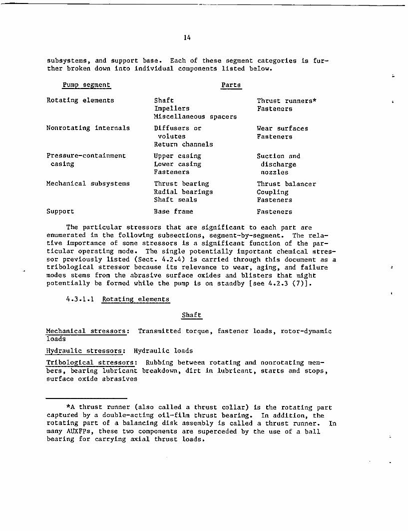
subsystems, and support base. Each of these segment categories is fur-ther broken down into individual components listed below.
Pump segment Parts
Rotating elements
Nonrotating internals
Pressure-containmentcasing
Mechanical subsystems
ShaftImpellersMiscellaneous spacers
Diffusers orvolutes
Return channels
Upper casingLower casingFasteners
Thrust bearingRadial bearingsShaft seals
Thrust runners*Fasteners
Wear surfacesFasteners
Suction anddischargenozzles
Thrust balancerCouplingFasteners
Support Base frame Fasteners
The particular stressors that are significant to each part areenumerated in the following subsections, segment-by-segment. The rela-tive importance of some stressors is a significant function of the par-ticular operating mode. The single potentially important chemical stres-sor previously listed (Sect. 4.2.4) is carried through this document as atribological stressor because its relevance to wear, aging, and failuremodes stems from the abrasive surface oxides and blisters that mightpotentially be formed while the pump is on standby [see 4.2.3 (7)].
4.3.1.1 Rotating elements
Shaft
Mechanical stressors: Transmitted torque, fastener loads, rotor-dynamicloads
Hydraulic stressors: Hydraulic loads
Tribological stressors: Rubbing between rotating and nonrotating mem-bers, bearing lubricant breakdown, dirt in lubricant, starts and stops,surface oxide abrasives
*A thrust runner (also called a thrust collar) is the rotating partcaptured by a double-acting oil-film thrust bearing. In addition, therotating part of a balancing disk assembly is called a thrust runner. Inmany AUXFPs, these two components are superceded by the use of a ballbearing for carrying axial thrust loads.
15
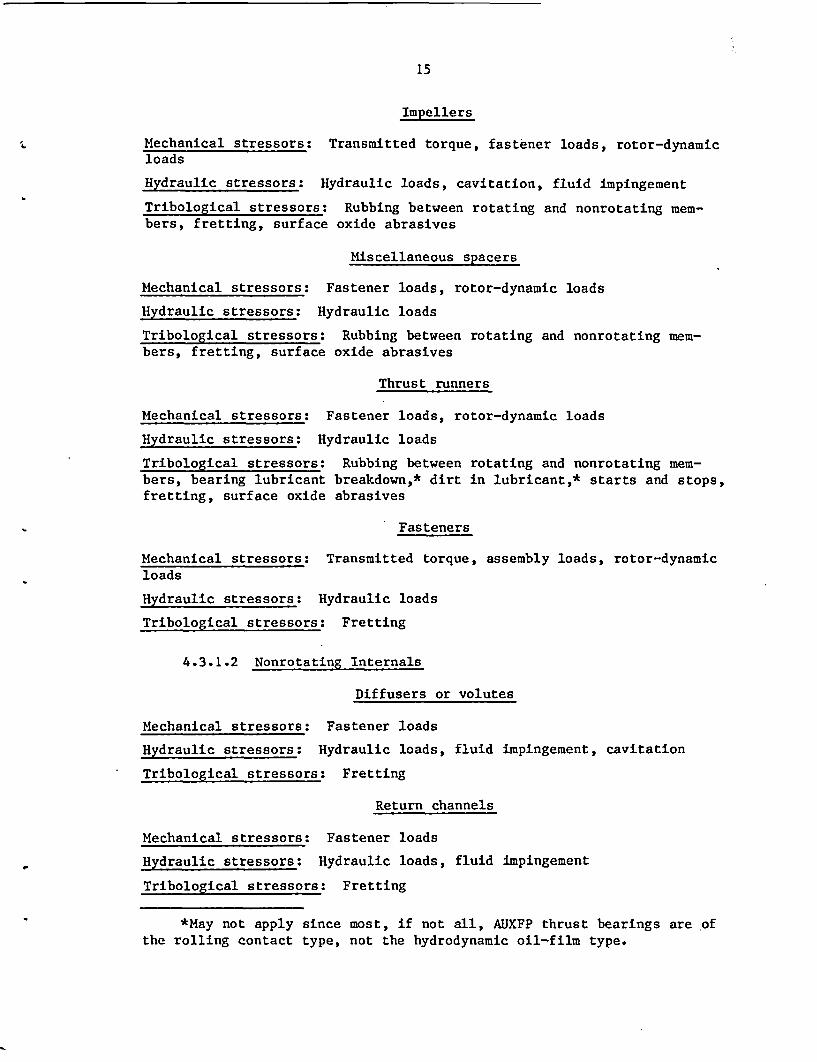
Impellers
Mechanical stressors: Transmitted torque, fastener loads, rotor-dynamicloads
Hydraulic stressors: Hydraulic loads, cavitation, fluid impingement
Tribological stressors: Rubbing between rotating and nonrotating mem-bers, fretting, surface oxide abrasives
Miscellaneous spacers
Mechanical stressors: Fastener loads, rotor-dynamic loads
Hydraulic stressors: Hydraulic loads
Tribological stressors: Rubbing between rotating and nonrotating mem-bers, fretting, surface oxide abrasives
Thrust runners
Mechanical stressors: Fastener loads, rotor-dynamic loads
Hydraulic stressors: Hydraulic loads
Tribological stressors: Rubbing between rotating and nonrotating mem-bers, bearing lubricant breakdown,* dirt in lubricant,* starts and stops,fretting, surface oxide abrasives
Fasteners
Mechanical stressors: Transmitted torque, assembly loads, rotor-dynamicloads
Hydraulic stressors: Hydraulic loads
Tribological stressors: Fretting
4.3.1.2 Nonrotating Internals
Diffusers or volutes
Mechanical stressors: Fastener loads
Hydraulic stressors: Hydraulic loads, fluid impingement, cavitation
Tribological stressors: Fretting
Return channels
Mechanical stressors: Fastener loads
Hydraulic stressors: Hydraulic loads, fluid impingement
Tribological stressors: Fretting
*May not apply since most, if not all, AUXFP thrust bearings are ofthe rolling contact type, not the hydrodynamic oil-film type.

16
Wear surfaces
Mechanical stressors: Assembly loads, rotor-dynamic loads
Hydraulic stressors: Fluid impingement
Tribological stressors: Rubbing between rotating and nonrotating men-bers, starts and stops, surface oxide abrasives
Fasteners
Mechanical stressors: Assembly loads, vibration
Hydraulic stressors: Hydraulic loads
Tribological stressors: None
4.3.1.3 Pressure-containment casing
Upper casing
Mechanical stressors: Assembly loads, piping forces, seismic loads,vibration
Hydraulic stressors: Hydraulic loads, fluid impingement, internal pres-sure
Tribological stressors: None
Lower casing
Mechanical stressors: Assembly loads, piping forces, seismic loads,vibration
Hydraulic stressors: Hydraulic loads, fluid impingement, internal pres-sure
Tribological stressors: None
Suction and discharge nozzles
Mechanical stressors: Assembly loads, piping forces, seismic loads,vibration
Hydraulic stressors: Hydraulic loads, fluid impingement, internal pres-
sure
Tribological stressors: None
17
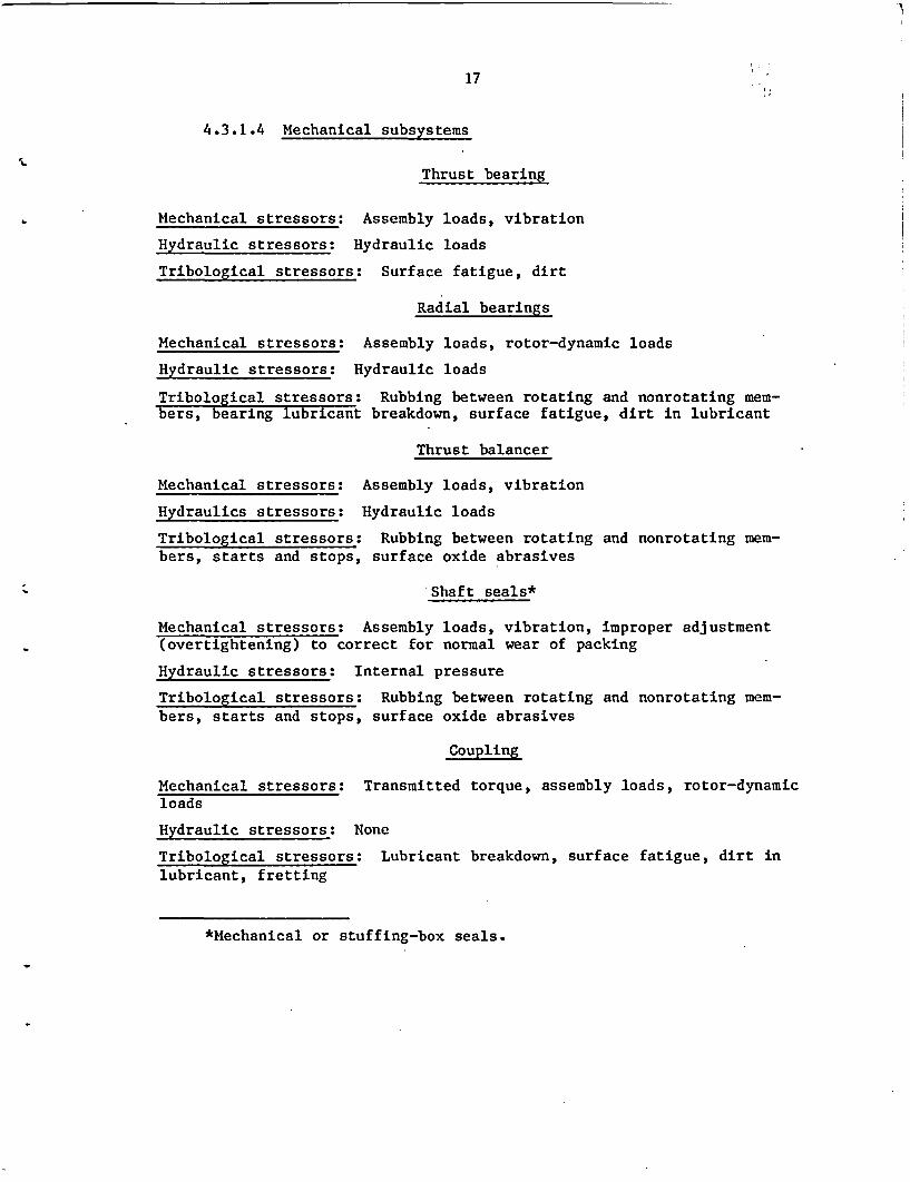
4.3.1.4 Mechanical subsystems
Thrust bearing
Mechanical stressors: Assembly loads, vibration
Hydraulic stressors: Hydraulic loads
Tribological stressors: Surface fatigue, dirt
Radial bearings
Mechanical stressors: Assembly loads, rotor-dynamic loads
Hydraulic stressors: Hydraulic loads
Tribological stressors: Rubbing between rotating and nonrotating mem-bers, bearing lubricant breakdown, surface fatigue, dirt in lubricant
Thrust balancer
Mechanical stressors: Assembly loads, vibration
Hydraulics stressors: Hydraulic loads
Tribological stressors: Rubbing between rotating and nonrotating mem-bers, starts and stops, surface oxide abrasives
Shaft seals*
Mechanical stressors: Assembly loads, vibration, improper adjustment(overtightening) to correct for normal wear of packing
Hydraulic stressors: Internal pressure
Tribological stressors: Rubbing between rotating and nonrotating mem-bers, starts and stops, surface oxide abrasives
Coupling
Mechanical stressors: Transmitted torque, assembly loads, rotor-dynamicloads
Hydraulic stressors: None
Tribological stressors: Lubricant breakdown, surface fatigue, dirt inlubricant, fretting
*Mechanical or stuffing-box seals.
18
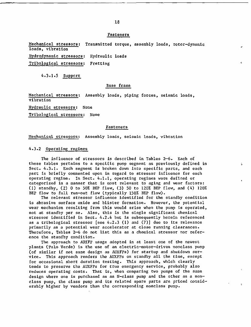
Fasteners
Mechanical stressors: Transmitted torque, assembly loads, rotor-dynamicloads, vibration
Hydrodynamic stressors: Hydraulic loads
Tribological stressors: Fretting
4.3.1.5 Suppcrt
Base frame
Mechanical stressors: Assembly loads, piping forces, seismic loads,vibration
Hydraulic stressors: None
Tribological stressors: None
Fasteners
Mechanical stressors: Assembly loads, seismic loads, vibration
4.3.2 Operating regimes
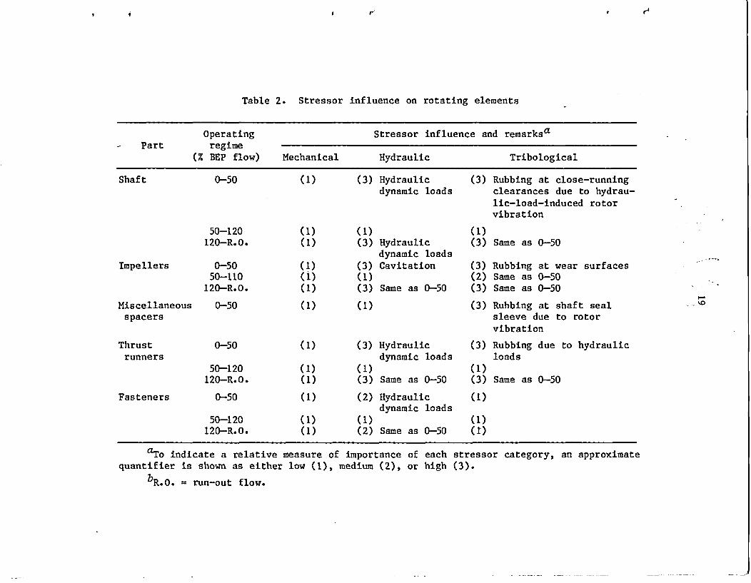
The influence of stressors is described in Tables 2-6. Each ofthese tables pertains to a specific pump segment as previously defined inSect. 4.3.1. Each segment is broken down into specific parts, and eachpart is briefly commented upon in regard to stressor influence for eachoperating regime. In Sect. 4.1.1, operating regimes were defined orcategorized in a manner that is most relevant to aging and wear factors:(1) standby, (2) 0 to 50% BEP flow, (3) 50 to 120% BEP flow, and (4) 120%BEP flow to full run-out flow (typically 150% BEP flow).
The relevant stressor influence identified for the standby conditionis abrasive surface oxide and blister formation. However, the potentialwear mechanism resulting from this would arise when the pump is operated,not at standby per se. Also, this is the single significant chemicalstressor identified in Sect. 4.2.4 but is subsequently herein referencedas a tribological stressor [see 4.2.3 (1) and (7)] due to its relevanceprimarily as a potential wear accelerator at close running clearances.Therefore, Tables 2-6 do not list this as a chemical stressor nor refer-ence the standby condition.
The approach to AUXFP usage adopted in at least one of the newestplants (Palo Verde) is the use of an electric-motor-driven nonclass pump(of similar if not same design as AUXFPs) for startup and shutdown ser-vice. This approach renders the AUXFPs on standby all the time, exceptfor occasional short duration testing. This approach, which clearlytends to preserve the AUXFPs for true emergency service, probably alsoreduces operating costs. That is, when comparing two pumps of the samedesign where one is purchased as an N-class pump and the other as a non-class pump, the class pump and its related spare parts are priced consid-erably higher by vendors than the corresponding nonclass pump.
r V V4~~~~~~~~~~~~~~ -
Table 2. Stressor influence on rotating elements
Operating Stressor influence and remarksa- Part regime
(% BEP flow) Mechanical Hydraulic Tribological
Shaft 0-50 (1) (3) Hydraulic (3) Rubbing at close-runningdynamic loads clearances due to hydrau-
lic-load-induced rotorvibration
50-120 (1) (1) (1)120-R.0. (1) (3) Hydraulic (3) Same as 0-50
dynamic loadsImpellers 0-50 (1) (3) Cavitation (3) Rubbing at wear surfaces
50-110 (1) (1) (2) Same as 0-50120-R.O. (1) (3) Same as 0-50 (3) Same as 0-50
Miscellaneous 0-50 (1) (1) (3) Rubbing at shaft sealspacers sleeve due to rotor
vibration
Thrust 0-50 (1) (3) Hydraulic (3) Rubbing due to hydraulicrunners dynamic loads loads
50-120 (1) (1) (1)120-R.O. (1) (3) Same as 0-50 (3) Same as 0-50
Fasteners 0-50 (1) (2) Hydraulic (1)dynamic loads
50-120 (1) (1) (1)120-R.0. (1) (2) Same as 0-50 (1)
aTo indicate a relative measure of importance of each stressor category, an approximatequantifier is shown as either low (1), medium (2), or high (3).
bR.O. = run-out flow.
,D

Table 3. Stressor influence on nonrotating internals
Operating Stressor influence and remarksaPart regime
(% BE? flow) Mechanical Hydraulic Tribological
Diffusers or 0-50 (1) (3) Unsteady flow (1)volutes forces
50-120 (1) (2) Same as 0-50 (1)120-R.0. (1) (3) Same as 0-50 (1)
Return 0-50 (1) (2) Unsteady flow (1)channels 50-120 (1) (1) (1)
120-R.0. (1) (2) Same as 0-50 (1)
Wear surfaces 0-50 (1) (1) (3) Rubbing due to rotorvibration
50-120 (1) (1) (2) Same as 0-50120-R.0. (1) (1) (3) Same as 0-50
Fasteners 0-50 (1) (2) Hydraulic (1)loads
50-120 (1) (1) (1)120-R.0. (1) (2) Same as 0-50 (1)
aTo indicate a relative measure of importance of each stressor category, anapproximate quantifier is shown as either low (1), medium (2), or high (3).
bR.O. = run-out flow.
03

0 *21
Table 4. Stressor influence on pressure-containment casing
Operating Stressor influence and remarksaPart regime
(% BEP flow) Mechanical Hydraulic Tribological
Upper casing 0-50 (1) (2) Near shutoff (1)head, over-pressure maycause casingdistortionsufficient toallow exces-sive leakageat casing splitline
50-120 (1) (1) (1)
120-R.O. (1) (I) (1)
Lower casing 0-50 (1) (2) Near shut-off (1)head, over-pressure maycause casingdistortionsufficient toallow excessiveleakage at cas-ing split line
50-120 (1) (1) (1)120-R.O. C1) (1) Cl)
Suction and All oper- C1) (1) (1)discharge atingnozzles regimes
Fasteners All oper- (1) C1) (1)atingregimes
aTo indicate a relative measure of importance of each stressor category, anapproximate quantifier is shown as either low (1), medium (2), or high (3).
bR.O. - run-out flow.
_

22
Table 5. Stressor influence on mechanical subsystems
Operating Stressor influence and remarksaPart regime
(% BEP flow) Mechanical Hydraulic Tribological
Thrust 0-50 (1) (1) (3) Axial hydraulic loadbearing (static and dynamic)
50-120 (1) (1) (1)120-R.0. (1) (1) (3) Same as 0-SO
Radial 0-50 (1) (1) (3) Dynamic loads frombearing hydraulic forces
50-120 (1) (1) (1)120-R.0. (1) (1) (3) Same as 0-50
Thrust 0-50 (1) (1) (3) Radial and axial dynamicbalancer loads can cause rubbing
50-120 (1) (1) (2) Static loads can increasegradually with use aswear-ring clearanceopens up via normal wear
120-R.0. (1) (1) (3) Same as 0-50
Seals 0-50 (3) POvertight packing gland (3) PExcessive rubbing possi-p - for pack- causes excessive wear rate ble due to dynamic hy-
ing gland draulic forcestype seals 50-120 (3) PSame as 0-50 (2) mPotential for oxide
m - for mechani- abrasives to cause wearcal type under all operatingseals regimes
120-R.0. (3) PSame as 0-50 (1) PSame as 0-50(2) mExcessive vibration (3) PSame as 0-50
Coupling 0-50 (3) Axial rotor dynamic loads (3) Axial rubbing betweenoriginating at the mating teeth on gearimpellers couplings
50-120 (1) (1)120-R.0. (3) Same as 0-50 (3) Same as 0-50All (2) Breakdown or loss of
lubricant in gear cou-plings
(2) Running time on life-rated parts, fretting
aTo indicate a relative measure of importance of each stressorquantifier is shown as either low (1), medium (2), or high (3).
bR.O. - run-out flow.
category, an approximate
23
Table 6. Stressor influence on support
Part Operating Stressor influence and remarksregime Mechanical Hydraulic Tribological
Base frame All regimes (1) None None
Fasteners All regimes (1) None None
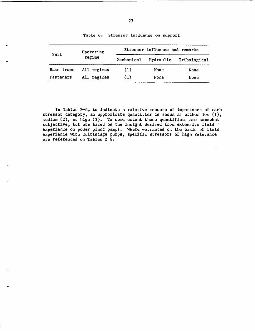
In Tables 2-6, to indicate a relative measure of importance of eachstressor category, an approximate quantifier is shown as either low (1),medium (2), or high (3). To some extent these quantifiers are somewhatsubjective, but are based-on the insight derived from-extensive field -
-experience on power plant pumps. Where warranted on the basis of fieldexperience with multistage pumps, specific stressors of high relevanceare referenced on Tables 2-6.
24
5. OPERATING EXPERIENCE*
The primary basis for information, insights, conclusions, and recom-mendations given in this report was the extensive data collection devel-oped by Energy Research and Consultants Corporation from design, trouble-shooting, and redesign experience. This collection was augmented throughexamination of nuclear power plant operating experience records as dis-cussed below.
This section summarizes AUXFP aging information obtained from vari-ous nuclear power plant operating experience records. Several LicenseeEvent Report (LER)-based pump failure studies were examined for relevantpump operating and failure information. While these documents do notalways contain specific pump aging-related failure data, the operatingexperience summaries and failure cause data, along with the overallanalysis results, are helpful in understanding the aging degradation ofpumps.
A number of operating experience data bases for nuclear power plantswere examined for this report:
* LER file* Nuclear Plant Reliability Data System (NPRDS)o In-Plant Reliability Data System (IPRDS)
Specific information needed for AUXFP failure characterization in-cludes: (1) failure modes, causes, and mechanisms; (2) frequencies offailures; (3) methods of failure detection - incipient, degraded, catas-trophic; (4) maintenance actions; and (5) modifications resulting fromfailures.
Each of these items serves to build a failure "signature" that, whentaken in total, can provide a comprehensive assessment of the componentfailure.
Unfortunately, no single data base provides all of the informationdesired for each failure. But each data base does possess some usefuldata elements that can be extracted for pump failure study. Table 7lists the information available from various sources of operating experi-ence. A summary of pump failure information available from each identi-fied data source is contained in Appendix B.
5.1 Failure Modes and Failure Causes
The primary reported failure causes of AUXFPs were failure of thebearings, followed by shaft packing and seal failures. The predominantreported failure mechanism was improper or insufficient lubrication orcooling. Maintenance errors (that were not readily apparent) and wearwere other major reported pump failure mechanisms. Wear of bearings,
*Work performed by G. A. Murphy, ORNL Nuclear Operations AnalysisCenter.

25
Table 7. Summary of AUXFP pump failure information availablefrom operating experience and plant documents
Operating experience Plant-specific
Data/sourcea data bases documents
LERb NPRDSb IPRDSb SAR SD TS ISI/IST
Pump type and X X X Xdescription
Manufacturer and X Xmodel No.Operating environment X X XFailure cause 0 XFailure mechanism 0 0Discrete failed part 0 XMaintanance action 0 0 XModification to prevent 0 0 Xrecurrence
Failure trend data X XIncipient failure X X Xdetection
Specific application X X X
aAcronyms
IPRDSISVI/ST
LERNPRDS
SARSDTSX0
In-Plant Reliability Data StudyIn-Service Inspection/In-Service Testing ProgramLicensee Event ReportNuclear Plant Reliability Data SystemSafety Analysis Report(Plant) System DescriptionTechnical Specification/Surveillance Test ProgramGenerally availableOccasionally included in failure report
bExamined in this study.

26
packing, and seals is anticipated with extended use, but the factorsmentioned above can accelerate the wear.
5.2 Frequency of Failure
No frequency of failure data for the AUXFP (as defined in this re-port) are available from data sources examined in this study. Numericalvalues published by NPRDS (and in IEEE-500, 1984) are derived from fail-ure of pump function, which could include numerous components - valves,instrumentation, controls, etc. - all associated with the pump function.For example, an NPRDS data request for failures of AUXFPs yielded 70records. Of the 70 records, only 14 (20%) reported a failure of thepump; the balance of the records described personnel and maintenanceerrors or failure of peripheral equipment that disabled the pump func-tion. Similarly, the LER data base search for failure of AUXFPs yielded1139 events. Only 53 events (4.6%) involved pump failures; the balanceagain described loss of pump function.
5.3 Methods of Detection
In the 14 NPRDs and 53 LER events, nearly one-half of the failureswere detected during surveillance or other tests. About one-third of thefailures occurred while the pump was in operation.
5.4 Maintenance Action
Listed maintenance action for the failure events, consisted mainlyof replacing a worn or broken subcomponent. In less than 10% of thefailures modifications were indicated as required to return the pump toservice.
5.5 Modifications Resulting from Failures
Operating experience data bases do not always contain detailed de-scriptions of postfailure modifications. Some of the data included thefollowing:
o impeller modifications were generally made to meet head-flow re-quirements, reduce stress in the key-way area, and increase clear-ance between the hub and the labyrinth rings;
• maintenance and repair procedures were continually revised to in-clude proper alignment of pump subcomponents;
* bearing and packing cooling often required modification to preventoverheating; and
* special training for maintenance personnel complements improvedrepair procedures to gain overall pump reliability.
27
6. FAILURE MODES AND FAILURE CAUSES
In Sect. 5, failure modes and causes were introduced within thecontext of "operating experience," relying upon the available data-basestherein referenced. However, that information provides primarily sparsestatistics for recorded failure experiences. Furthermore, the total num-ber of operating hours on AUXFPs, industry-wide, is probably insufficientto establish from such data potential cause-and-effect relationshipsbetween failure modes and causes. Fortunately, there is a much largerbody of applicable experience stemming from (1) feedwater pumps specifi-cally and (2) turbomachinery and rotating machinery in general.
It is recognized that AUXFPs are subjected to intermittent operationwhich makes the experience differ from that of feedwater pumps, but thereis not an available data base with better correspondence. There are manysimilarities in design and function between the two to justify use offeedwater pump experience. Thus, what has become fairly common practicewith similar machinery in identifying failure modes and causes must beused to provide viable approaches to maximize operational readiness ofAUXFPs.
6.1 Failure Modes
Failure modes must be defined carefully and uniquely because theword "failure," as herein used, has a much broader meaning than justtotal loss of function due to sudden breakage. The following subsectionsdefine failure modes.
6.1.1 Failure to operate
1. Required driver torque is applied to coupling, but rotor does notrotate.
2. Power interruption by automatic tripping devices, such as overspeedtrip on turbine-driven units. This includes the possibility of atrue trip or one resulting from malfunction of the trip device.
6.1.2 Failure to operate as required
1. Failure to provide required head-capacity pumping characteristic.2. Critical parameter measurements (e.g., vibration, bearing tempera-
ture, delivered flow) outside acceptable ranges. Although the pumpis still able to perform the design function and is, therefore, notfailed, it is either repaired or replaced because it might fail inthe immediate future. Because the pump has to be taken out of ser-vice to repair the potential problem, these events are consideredfailures.
28
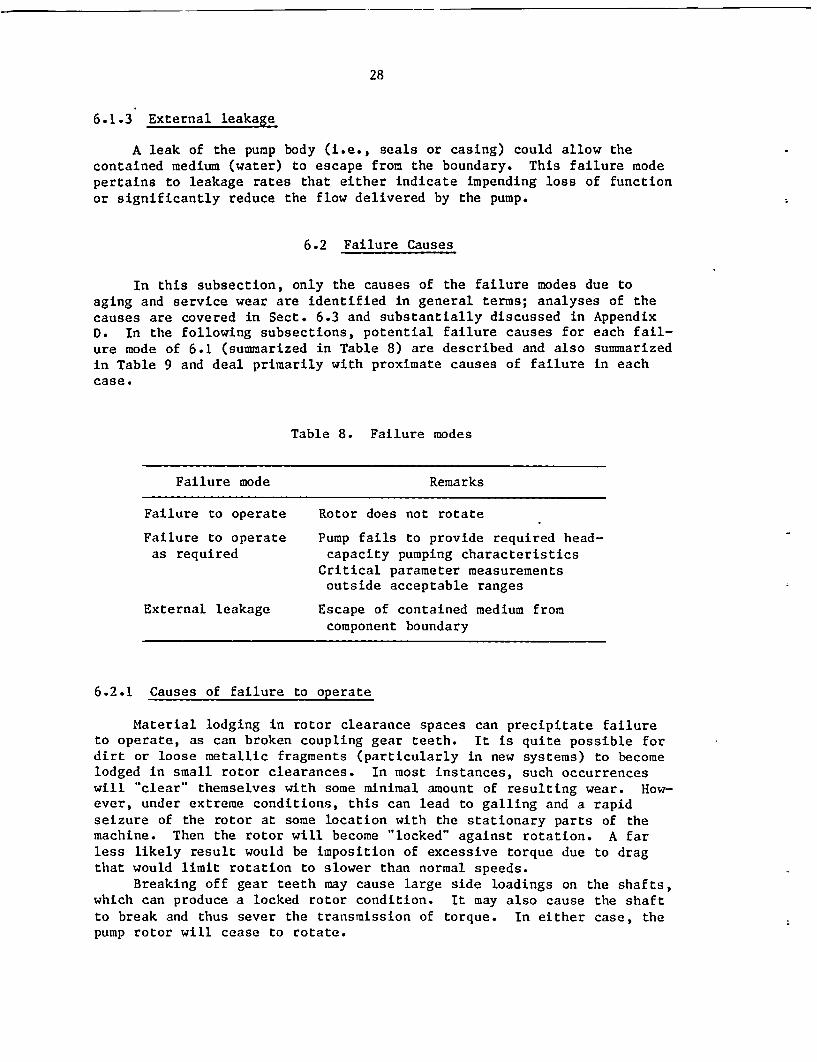
6.1.3 External leakage
A leak of the pump body (i.e., seals or casing) could allow thecontained medium (water) to escape from the boundary. This failure modepertains to leakage rates that either indicate impending loss of functionor significantly reduce the flow delivered by the pump.
6.2 Failure Causes
In this subsection, only the causes of the failure modes due toaging and service wear are identified in general terms; analyses of thecauses are covered in Sect. 6.3 and substantially discussed in AppendixD. In the following subsections, potential failure causes for each fail-ure mode of 6.1 (summarized in Table 8) are described and also summarizedin Table 9 and deal primarily with proximate causes of failure in eachcase.
Table 8. Failure modes
Failure mode Remarks
Failure to operate Rotor does not rotate
Failure to operate Pump fails to provide required head-as required capacity pumping characteristics
Critical parameter measurementsoutside acceptable ranges
External leakage Escape of contained medium fromcomponent boundary
6.2.1 Causes of failure to operate
Material lodging in rotor clearance spaces can precipitate failureto operate, as can broken coupling gear teeth. It is quite possible fordirt or loose metallic fragments (particularly in new systems) to becomelodged in small rotor clearances. In most instances, such occurrenceswill "clear" themselves with some minimal amount of resulting wear. How-ever, under extreme conditions, this can lead to galling and a rapidseizure of the rotor at some location with the stationary parts of themachine. Then the rotor will become "locked" against rotation. A farless likely result would be imposition of excessive torque due to dragthat would limit rotation to slower than normal speeds.
Breaking off gear teeth may cause large side loadings on the shafts,which can produce a locked rotor condition. It may also cause the shaftto break and thus sever the transmission of torque. In either case, thepump rotor will cease to rotate.

O. i
Table 9. Suimnaryof failure ,odes and causes
Failure Segments and parts Relative probabilitymodea involved Failure causes Failure mechanisms of occurrenceb
I Rotating element at close Binding between rotor and Dirt or metallic debris, Mclearance with stationary stationary parts galling and seizingparts Loss of drive torque Coupling or pump shaft
Pump shaft and coupling breakage H
2 Impellers and nonrotating Seizure or breakage of shaft, Hydraulic forces at high and H rLinternals, seals, wear breakage of impellers or non- v low flows, material fatigue, Isurfaces, bearings, thrust rotating internals, bearing high vibration
' balancer, shaft, coupling or thrust balancer seizure
2 Impellers and nonrotating Deterioration of pumping ca- Hydraulic forces, high vi- Hinternals, interstage pacity resulting from rapid bration, cavitationsealing clearances (wear wear, structural failure ofsurface) internals
2 Rotating element, seals, High vibration, high bearing All of the above under H FAtq,-Abearings, thrust balancer, temperature, abnormal seal failure mode 2internals leak-off flow, abnormal pump
performance
2 Speed control governor, Overspeed trip Large speed overshoot H or L, dependingoverspeed trip device on start-up due to ex- upon system con-
cessively fast speed-up figurationTrue overspeed trip
3 Shaft seals, casing Deterioration or breakage High vibration, improper Hof seal components packing adjustment
Leakage through casing Casing distortion and Lstatic sealing joint "wire drawing'
Erosion, corrosion, orstructural failure ofcasing
aFailure mode legend: (1) Failure to operate(2) Failure to operate as required(3) External leakage
bL - Low
H - MediumH - High
'1�
/
30
The one automatic tripping action that is built into all turbine-driven AUXFPs is an overspeed trip. In a number of plants and some quiterecently, overspeed tripping at startup has been a problem. When startupaction is initiated, the steam valve in the line to the drive turbine(typically a 6-in. line) fully opens, and maximum torque is applied tothe pump, resulting in rapid acceleration to and above operating speed;this occurs in about I s. Before the speed control governor has time topressurize its oil system and react correctively, the overspeed tripvalue of speed is exceeded and the automatic trip mechanism closes thesteam valve, shutting down the machine (see Appendix C for additionaldiscussion).
6.2.2 Causes of failure to operate as required
Causes include journal bearing or thrust bearing failure, gallingand seizure of the thrust balancer, sudden shaft breakage, sudden disin-tegration of an impeller(s) or detachment of a stationary (diffuser)vane(s). None of these causes are uncommon in HHPS multistage centrifu-gal pumps. An additional cause is deterioration by cavitation of thefirst-stage impeller; others are unacceptable critical parameter readingsand automatic tripping.
Operation of these pumps "far" from the BEP flow induces very strongunsteady flow conditions within the pump hydraulic passages. The strongunsteady flow phenomena result in very large dynamic forces (radial andaxial) on pump internals, both stationary and rotating parts. The immedi-ate by-product is high-amplitude vibration that causes rapid wear atcritical clearances in the pump due to severe vibration-induced rubbing.This leads to rapid increase in stage-to-stage leakage, resulting in mea-surable reduction in delivered pump capacity. In addition, these largedynamic fluid forces can break loose large pieces of diffuser vanes, im-peller side plates, and impeller vanes. Such rapid deterioration of pumpinternals will naturally result in considerable reduction in deliveredcapacity of the pump as well as catastrophic structural failure.
Deterioration of the first-stage impeller due to cavitation erosionalso degrades performance. Not having sufficient Net Positive SuctionHead (NPSH) available at the pump inlet over the entire operating rangeis sufficient to produce this type of first-stage impeller damage. Thenet effect will be a slow deterioration in the delivered capacity of thepump.
Monitored parameters such as vibration, bearing temperature, sealleakage, delivered flow, and rotor speed are typically measured and re-corded continuously on main power cycle pumps (e.g., main feedwater, con-densate, and reactor coolant pumps). At present, such monitoring capa-bility is not typically installed on AUXFPs. One or more of theseparameters can be reliable indicators of an impending pump failure aswell as being correlated with aging and service wear factors and analy-ses. Obviously, an upward or downward trend away from normal seal leak-off flow is a fairly sure indication that a seal is wearing out or needsadjustment. An upward trend in vibration level or a sudden increase invibration is a sure indication of impending pump malfunction (if properaction is not taken). Temperatures of journal bearings and especially
31
oil-film thrust bearings are indicative of impending difficulties whenthey climb above established limits for reliable operation. Furthermore,excessive vibration or elevated bearing temperature has serious deterio-rating effects on the pumps and thus requires immediate correctiveaction, regardless of the specific cause. A significant deterioration ofdelivered pump capacity would also be indicative of a potentially seriousproblem with the pump that should be immediately investigated and cor-rected.
The measured parameters by themselves may not divulge the fullnature of a problem. However, they can at least give warning that themachine must be shut down as soon as possible for further inspection andpossibly disassembly of the pump for inspection of internal parts for thepurpose of determining the probable cause(s) of out-of-normal-rangeparameter readings.
Any one of these monitored parameters or a combination thereof couldbe incorporated into various automatic tripping schemes. This is commonpractice for large steam turbine-generator units, reactor coolant pumps,main feedwater pumps, large fans, etc., primarily to detect potentiallycatastrophic failures before they occur and thus prevent costly damage.However, the "philosophy" behind using such tripping schemes on AUXFPsshould very definitely be given special examination. It would make nosense at all to trip an AUXFP during an emergency to save it from life-shortening wear due to excessive vibration or somewhat high bearing tem-peratures. The primary purpose of the AUXFP is to protect the reactorsystem, not to protect itself.
6.2.3 Causes of external leakage
Three causes are related to this failure mode. The first and mostcommon is failure of the shaft seals to properly control leakage to withinacceptable limits. This can occur either from an outright breakage of asealing component or from a progressively deteriorating seal that mayneed replacing or simply a tightening adjustment as in the case of stuff-ing-box type shaft seals.
The second cause is malfunction of the flat static sealing jointformed at the split between the upper and lower casing halves. Thoughfar less common than the first cause (i.e., shaft sealing malfunction),it is a possibility and does occur on structurally marginal split-casingmultistage centrifugal pumps. When it occurs, it generally indicatesthat the overall casing design is marginal from a rigidity or deflectionstandpoint, and the joint simply opens up a little at maximum pressureconditions; that is, at or near shutoff head, the casing design is notquite stiff enough. The worrisome aspect of this phenomenon is that"wire drawing" damage to the flat-joint sealing surfaces is a possibleby-product and thus a continually increasing leakage rate may develop,even at lower operating pressures, once the "wire drawing" erosion pro-gresses.
The third and least likely cause is associated with erosion, corro-sion, and structural failure of the pressure envelope. Based on exten-sive field experience with all types of multistage high-pressure centrifu-gal pumps, this type of failure should be categorized as one of extremelylow probability.

32
6.3 Failure Cause Analysis
The purpose of this section is to provide more specific discussionon the various failure-mode causes, based on troubleshooting experienceand insight on AUXFPs, main feedwater and booster pumps (both nuclear andfossil plants), and multistage centrifugal pumps for other service suchas in petrochemical applications. The failure modes herein identifiedfor AUXFPs are inherent as well in these other multistage pump applica-tions.
HHPS multistage centrifugal pumps remain an engineering challenge.Unfortunately, this type of pump has not been viewed by manufacturers andusers as the high-technology device that it really is. The amount ofengineering research in the United States devoted to HHPS pumps over thelast 25 years has been rather insignificant (see Appendix D).
The fact that AUXFPs spend most of their plant life in the standbymode is at the same time an advantage and a disadvantage. The advantageis that they are, on the average, less likely to fail from wear thantheir "big brothers" - the boiler feedwater or nuclear feedwater pumpsthat are operated continuously. On the other hand, whatever inherentdesign weaknesses exist in present AUXFP designs, they are less likely tofully surface on the short-term basis - a disadvantage that gives consid-erable importance to the main theme of this report.
Through recent field troubleshooting, specifically on AUXFPs and onquite similar pumps for nonclass applications, some specific factors havesurfaced that impact significantly on the reliability of AUXFPs. Thesefactors are discussed in the following subsections.
6.3.1 Large dynamic forces and vibrations created by pumphydraulics
Further review of stressor influence factors (Tables 2-6) and, cor-respondingly, the summary of failure modes and causes (Table 9) clearlyshows that the large dynamic forces resulting from pump internal flowsis the major failure-mode factor. Within this context, the most severeoperating mode is at low flow (i.e., close to shutoff conditions). Thehydraulic forces generated are large and the resulting vibration levelsare high. Consequently, AUXFPs are installed with a bypass or recircula-tion line, which has long been standard practice on nuclear main feed-water pumps and boiler feedwater pumps.
A bypass flow line of 25% best-efficiency capacity ensures that nomatter how low the delivered pumping capacity is at part-load operation,the pump internally never "sees" less than 25% flow. In main feedwaterand boiler feedwater pumps, the bypass flow line is valved so that, atflow rates above bypass flow, the full capacity of the pump is availableand the energy loss associated with bypass flow is incurred only underlow-flow operation. This same approach of valving the bypass flow linehas been applied in many AUXFP installations. However, an emerging trendhas been to remove this bypass line valve from already installed AUXFPsor to delete it in newer plants; that is, to eliminate completely thepossibility of having a bypass valve malfunction in the closed positionor to be mistakenly left closed.

33
The required flow of main boiler and nuclear feedwater pump bypassflow lines is typically a relevant evaluation factor in pump vendors'sales proposals. This is because the larger the bypass flow required,the more pumping energy is wasted at part-load operation. In retrospect,pump manufacturers now indicate that this same evaluation philosophy wasapplied in the purchase of AUXFPs, forcing them to compete by providingsmall required (typically 10 to 15%) bypass flow figures. However, theenergy consideration just noted is surely not relevant to safety-relatedstandby pumps such as AUXFPs. Much more attention and engineering in-vestigation is warranted, and each AUXFP design should be thoroughlytested to determine the true safe minimum flow rate. Because energyconsumption is not a major consideration in AUXFP service, one simply cansize the pump so that its full capacity is sufficient to always ".waste"the bypass flow and, thus, protect the pump from the abusive operationand accelerated wear that it could otherwise encounter.
Obviously, the larger the percentage of BEP flow routed through thebypass line, the better it is for the pump. In well-engineered pumps, 25to 35% bypass flow is sufficient to avoid the dangerous range of off-design operating flows (see Appendix D and Fig. D.1). However, for somepumps any flow below 50% of best-efficiency capacity may cause severevibration. This raises a crucial and not yet widely recognized (and thusunresolved) potential safety-related problem. Apparently, determinationof an appropriate AUXFP bypass flow rate has been done only on a plant-by-plant basis and then only in response to piping vibration problems,not in appreciation of AUXFP abuse considerations.
6.3.2 Shaft breakage
Several factors, identified through field troubleshooting, result inshaft breakage as an initiating event in a failure (see Appendix D foradditional discussion). Because of the presence of large hydraulicforces, any design or quality control (QC) shortcoming affecting theshaft can readily lead to shaft breakage. A common such design flaw isan undersized shaft diameter, generally motivated to improve pump hydrau-lics by providing larger impeller inlet flow areas.
In some failures, it was determined that the shaft failed as a con-sequence of the retaining bolt (which retains the runner of the thrustbalancer) not being square with the mating shaft shoulder when fullytightened. This results in high bending prestress of the shaft, leadingto fatigue-initiated breakage of the shaft. This is a QC correctableproblem.
Another source of shaft breakage observed in the field is improperheat treatment of the shaft. This is also a QC correctable problem.
A further source of shaft failure arises from overheating caused byovertightening of a shaft seal stuffing-box gland. This is a maintenancecorrectable problem. Stuffing-box shaft seals may require frequenttightening adjustment to control shaft seal leakage, even in the standbymode. Thus, one can envision an inadvertent overtightening of the pack-ing gland in an effort to reduce the required frequency of adjustment.Although AUXFP manufacturers do not use forgings for the shaft, this moreexpensive option would certainly improve shaft durability and thus in-crease reliability.
34
6.3.3 Impeller and diffuser breakage
If the bypass flow line is undersized (see Sect. 6.3.1), then impel-lers and diffusers are among those pump internal components that are sub-jected to severe dynamic loading at low-flow operation. This can createfatigue failure resulting from cyclic stresses.
Even if the bypass flow line is adequately sized, a too small radialgap between impeller-vane outside diameter and diffuser-vane inside diame-ter frequently results in impeller and diffuser breakage. This breakageresults from high-amplitude shock loads at vane-passing frequency (seeFig. D.5). The offending factor here is poor hydraulic design. This canbe fixed in the field by experienced personnel and entails machining andrecontouring the diffuser vanes to a larger radial clearance with theimpeller. This fix also generally makes the pump run much quieter, whichby itself generally is indicative of improved internal hydraulic configu-ration.
Cavitation damage to the first-stage (i.e., suction-stage) impellercan result in structural failure of the impeller. Insufficient NPSH isa common problem of feedwater systems in general and stems from a widerange of mostly optimistic opinions on what constitutes adequate NPSH.
A significantly reduced potential for impeller and diffuser breakagecould be achieved if impellers were precision cast rather than using thelower quality sand castings as is presently done by all AUXFP vendors.
6.3.4 Thrust bearing and thrust balancer failures
Even for standardized pump configurations, there exist many possiblevariations that a vendor can tailor to meet a given application specifi-cation. For all the available designs and variations thereof, there issimply not adequate engineering test data on hydraulic axial thrust loadsover the full flow range of each specific design. Thrust loads changeconsiderably on a given pump as a function of flow, speed, and state ofwear at wear-ring stage-to-stage leakage control clearances. Essentially,the axial thrust loads are not accurately known over the full ranges thatfeedwater pumps are commonly required to operate. Consequently, thrustbalancers and thrust bearing failures in feedwater pumps are not uncommonbecause the inaccurate definition of axial thrust loads (both static anddynamic) often results in undersized thrust balancer and thrust bearingdesigns.
Excessive operating temperatures in thrust bearings are common symp-toms indicative of this overall problem. Furthermore, on thrust balan-cers, improper heat treatment and material property control result ingalling and seizing events, especially when combined with undersizedgeometries (see Appendix D for additional discussion).
6.3.5 Coupling breakage
Coupling breakage is not uncommon. The combination of excessivelylow-flow operation of the pump and an undersized thrust balancer canresult in excessive axial dynamic loads on the coupling. Additionally,when the radial gap between impeller and diffuser vanes is too small,
35
excessive coupling vibration at vane-passing frequency can readilydestroy the coupling (gear teeth).
Breakage of seal injection piping due to excessive vane-passingfrequency vibration also can occur when the impeller-to-diffuser radialgap is too small.
6.3.6 Seizure
Seizure is not uncommon in feedwater pumps and has been traced to avariety of causes including (1) excessive rotor vibration (both lateraland axial); (2) inadequate clearance at thrust balancer; (3) seizure-prone material hardness and geometry combination at impeller wear rings,thrust balancer, or any other close-running clearance; (4) overallhydraulic mismatch between impeller and diffuser; and (5) journal bearingfailure resulting from excessive rotor vibration, poor babbitt bonding tobearing shell, dirt in the lubrication oil system, or combinations ofthese.
36
7. RECOMMENDED MAINTENANCE, SURVEILLANCE, ANDMONITORING PRACTICES
AUXFPs spend most of their plant life in a standby mode. Conse-quently, present maintenance, surveillance, and monitoring practices arenot elaborate. Pump manufacturers are mainly concerned with other appli-cations involving continuous long-duration running where certain compo-nents clearly do wear out and where scheduled major overhaul and refur-bishment is common practice. Regarding AUXFPs, the manufacturers make nodefinitive recommendations.
At present, most AUXFP installations contain no monitoring devicesexcept for flow and head measurement, in contrast to continuously runningmachinery. Present AUXFP surveillance practice consists primarily ofperiodically* starting each pump for a short-duration test to verify itsoperational readiness.
7.1 Regular Maintenance
The only present regular maintenance activity pertains to shaftsealing components. In the normal standby mode, the shaft seals arestill subjected to upstream system pressure, that is, from a condensateor storage tank. This pressure is typically 2 to 4 atm and thus main-tains the shaft seals in a functional sealing mode, even though the shaftis not rotating.
Stuffing boxes as well as mechanical seals are in common use inAUXFPs. With stuffing-box shaft seals, the primary maintenance activityis to keep the packing gland properly adjusted. Based primarily on anobservation of excessive leakage, a tightening adjustment is made. How-ever, stuffing boxes must be allowed to maintain some continuous leakage.Overtightening of stuffing-box glands to eliminate leakage completelywill likely result (and has on AUXFPs) in severe operating problems whenthe AUXFP is put into a pumping mode, that is, at normal rotationalspeed. Overtightened stuffing-box glands result in excessive temperaturerise both in the packing and on the shaft, increasing considerably pack-ing wear and the probability of shaft breakage. In many plants, AUXFPstuffing-box packing glands are now maintained somewhat looser than wouldbe typical of non-AUXFP applications. Although this results in somewhathigher continuous leak-off flow, it is a prudent practice, since it givesa further safety margin against such heating problems and related poten-tial failures during any pumping mode.
With mechanical shaft seals, the leak-off flow in the standby modeshould be zero, if the seal is functioning properly. That is, at zeroshaft rotation, a mechanical seal essentially closes the flow path forshaft-end leakage. If a mechanical seal is observed to be leaking in thestandby mode, this is a strong indication that something is wrong with
*Plant Technical Specifications require operational readiness test-ing at least once every 3 months. However, in many plants, this testingis performed as frequently as once a month.

I
37
the seal, and thus it should be fixed or replaced as required to correctthe problem.
In addition to these seal maintenance items, lube-oil sight glasseson the AUXFP should be regularly inspected to check oil level. Mostother maintenance items would require some amount of disassembly to per-form and thus would be objectionable, unless there were strong indica-tions of pump malfunction, for example, as indicated by excessive vibra-tion.
7.2 Surveillance
7.2.1 Current surveillance practice and limitations
Unfortunately, AUXFPs are rarely installed with the type of moni-toring devices typical of equipment provided for continuous operationservice. Installed rotor vibration probes and bearing inside temperaturetransducers (e.g., babbitt-contacting thermocouples) have generally notbeen required by AUXFP purchaser specifications. Only in a very fewplants, where recurring AUXFP operating problems have otherwise beendetected, has such monitoring equipment been retrofitted. Thus, in mostplants, comprehensive surveillance of AUXFPs during pumping mode serviceis not readily done.
As noted in Sect. 4.3.2, some newer plants use a nonclass pump forstartup, shutdown, and any other nonemergency service. This "saves" theN-class AUXFPs for strictly emergency service with one important excep-tion. The Plant Technical Specification requires that, nominally everythree months, each N-class pump is put into a pumping mode for a shortperiod of time to demonstrate its continued operational readiness. Dur-ing this regular test, the loads imposed on the AUXFP depend on the by-pass flow line configuration. In most plants, the AUXFP bypass line is asingle line sized to pass 5 to 15%,of BEP flow. Thus, this type of test-ing could be the main contributor to wear and aging of various AUXFP com-ponents. In some newer plants (e.g., Palo Verde) an additional full-flowbypass line is provided to allow testing of the AUXFPs over the fulloperating flow range, even when the plant is operating in a normal gener-ating mode. However, in most plants, this test provides neither theproper operating range of flow nor sufficient running time to comprehen-sively trend and assess an AUXFP's "vital life signs," even if a fullcomplement of state-of-the-art monitoring devices were installed.
7.2.2 Interim recommendations for surveillanceand monitoring practices
Based upon the described impediments to comprehensive surveillanceand performance trending, some obvious interim recommendations can bemanifestly considered.
First, present auxiliary feedwater systems need to be studied formodifications that would permit ease of testing the AUXFPs over the en-tire range of flow, independent of the main feedwater system. One pos-sibility is to permanently install bypass flow lines to allow testing the
38
AUXFPs at operating conditions that fully simulate the various emergencypumping requirements that the AUXFPs have to meet. Built-in full-flowtesting capability could be engineered to avoid adversely affecting thereliability of the auxiliary feedwater system in normal and standby modes.This has been demonstrated at the Palo Verde plant.
Second, a full complement of permanently installed monitoring devicesshould be considered on every AUXFP. Major candidate parameters shouldinclude at least (1) rotor orbital motion; (2) oil-film bearing tempera-tures; (3) head, flow, and speed values; (4) rotor axial position; and(5) metal fragment and/or sound emission for early detection of incipientfailure of rolling contact bearings.
Third, a standardized sequence of full-service tests need to bedeveloped and performed at appropriate regular intervals. The full com-plement of parameters monitored could be appropriately analyzed, trendsestablished, and results compared over the accrued history of the pump.This data base could be used to indicate need for preventive maintenance,overhaul, and replacement of worn parts. Such monitoring and trendingsystems for rotating machines are now commercially available at a smallfraction of the cost of an N-class AUXFP. Section 8.2 provides a moredetailed discussion of parameter monitoring.
7.2.3 Interim recommendations for detailed inspection program
In addition to the comprehensive testing, surveillance, and monitor-ing approach recommended in the previous section, a detailed disassemblyand inspection of AUXFP internals could be carried out whenever the reac-tor is in a scheduled shutdown for a number of weeks, such as at refuelingtime.
During this disassembly, a number of procedures and reliabilityenhancing actions could be taken: (1) replace rolling contact bearings;(2) replace renewable components of mechanical shaft seals; (3) replaceany wear rings having clearance-doubling wear; (4) inspect impellers,diffuser vanes, and other hydraulic-passage internals for damage andreplace any damaged or significantly worn parts based upon conservativecriteria; (5) inspect journals, bearing surfaces, and thrust balancercomponents, replacing any distressed components; (6) inspect main sealingjoint surfaces at casing joint to detect any sign of leakage; (7) checkshaft for run-out (can readily occur through creeping) and correct asrequired by straightening or replacement of shaft; and (8) inspect andreplace any fastener that shows signs of distress. Section 8.1 providesa more detailed discussion of the overall topic of detailed inspection.

39
8. AGING AND SERVICE WEAR MONITORING
As described in Sect. 7.2, nearly all AUXFPs presently in serviceare installed with little or none of the specific parameter monitoringdevices that are commonly integrated into continuously running main powercycle equipment. Furthermore, most auxiliary feedwater systems are notpresently configured to facilitate regular periodic testing of AUXFPsover the complete range of flow rates that would simulate the variousemergency scenarios for which AUXFPs are installed. Consequently, withpresent typical installations, aging and service wear monitoring wouldhave to be based primarily upon a detailed and thorough inspection of thepump in the disassembled state. Unless specific operating problems arosewith a particular AUXFP, such a detailed inspection would be practicalonly during a scheduled plant shutdown, such as at refueling time.
Shaft seal leak-off flow is the one parameter that can be and typi-cally is readily monitored, both in the standby ready mode as well asrunning modes. In the following sections, monitoring specifics that areadvisable and can be readily performed with present typical configurationsare described. In addition, monitoring specifics that could furtherassist in aging and wear analyses, utilizing state-of-the-art monitoringpackages, are described for consideration as upgrading options.
8.1 Monitoring of Present Configurations
Here the discussion is aimed at existing configurations that typi-cally have available neither a full complement of state-of-the-art con-tinuous monitoring devices nor are set up to routinely run full-flowrange AUXFP tests.
8.1.1 Rotor binding check
The following is a simple procedure that is probably not commonlypracticed in existing plants although it is highly advisable. Just priorto starting the pump, the rotor should be hand rotated, grabbing it atthe coupling. Generally, a pair of nonslip gloves must be worn to accom-plish this. This procedure could also be performed at regular intervalseven if the pump is not about to be started. For safety reasons, thepump driver must be "tagged out." Naturally, this procedure should bedisregarded in the event of a true emergency startup of the pump.
If it is not possible to hand turn the rotor, then a suitable wrenchor wrenchlike device should be used to attempt a wrench-assisted handturning of the rotor. If this action fails to turn the rotor, then thecause of the binding can be identified and appropriate corrective actiontaken.
8.1.2 Shaft seal leak-off flow
8.1.2.1 Mechanical seals. Properly functioning mechanical sealsshould not exhibit leak-off flow large enough to be seen or measured. If
40
leakage is clearly visible, then the seal is potentially in need of partsreplacement and at least the reason for the leakage should be determinedand appropriate corrective action taken.
8.1.2.2 Packing gland (stuffing box) seals. This type of sealshould always leak a small amount to ensure that the packing gland hasnot been overtightened. Excessive leakage, which cannot be correctedthrough normal gland adjustment, could be indicative of worn or damagedcomponents in the seal subassembly. The defective or worn part(s) shouldbe replaced.
8.1.3 Disassembly and detailed inspection
The following subsections pertain to those aging and service wearmonitoring actions that require disassembly of the pump and that could beperformed during a scheduled plant outage, that is, at refueling time.To disassemble this type of split casing pump, the following steps aretaken: (1) the coupling is disengaged, (2) the journal bearing caps areremoved, (3) the shaft seals are removed, (4) the casing stud bolts areremoved and the upper casing half lifted off of the bottom casing half,and (5) the rotor is lifted out of the lower casing half. At this point,each wear ring will be loosely surrounding its respective impeller andcan be moved axially to hang on the adjacent shaft section so that theinside diameter of each wear ring can be measured.
Upon disassembly of the pump as outlined above, the following mea-surements and visual inspections can be made.
8.1.3.1 Journal bearings, journals, and thrust bearing. Visuallyinspect all bearing surfaces for evidence of (1) bearing metal (babbitt)fatigue cracks, (2) loss of babbitt-substrate bonding, (3) babbitt wipingor smearing, and (4) babbitt gouging that would occur from entrainedforeign matter in the oil. If any of the above deteriorations are inevidence, then the bearing should be replaced, or repaired to essentiallyas-new condition. The journals should also be inspected for signs ofdistress or wear. Specifically, measurable or visual evidence of surfacedeterioration, such as deep scratches, heat checking, or scoring shouldrequire refurbishment to return journal surfaces to their as-new condi-tion. If the journal surface distress is quite extreme, then the jour-nals may have to be chrome-plated to a sufficient thickness so thatresurfacing of the journals does not reduce the journal diameter to lessthan its original dimensional tolerance zone. If the journals and bear-ings are repaired during the same disassembly, the original bearingclearance could be preserved by remachining a rebabbitted bearing to aslightly reduced bore diameter, sufficient to offset any slight reductionin journal diameter resulting from redressing its surface.
The AUXFP thrust bearing is usually a rolling contact type, such asa double-row preloaded angular contact (duplex) ball bearing arrangement.This bearing can be inspected for signs of wear or damage although sub-surface fatigue cracks are not visible. However, such bearings are rela-tively inexpensive, and thus automatic replacement is strongly advised.
8.1.3.2 Shaft seals and mating rotor sleeves. For mechanical seals,the mating sealing surfaces (rotating and nonrotating parts) should beclosely inspected visually, with high magnification if necessary, to

41
determine the presence of any measurable signs of wear. Any evidence ofwear is sufficient cause to replace the worn seal component.
For stuffing-box seals, the rotor sleeve should be inspected forsigns of wear and/or surface finish deterioration. It is not uncommonfor the rotor sleeve to have deep grooves worn in from continual runningwith an excessively tightened packing gland. The shaft sleeve should bereplaced in any case where this inspection uncovers measurable wear orsurface deterioration. The packing material, though adjustable in ser-vice to compensate for wear, will eventually need replacing. It is inex-pensive and thus should be automatically replaced at any such disassembly-for-wear inspection, using the same rationale previously applied to roll-ing contact bearings.
8.1.3.3 Coupling. The disassembled coupling should be inspectedfor any deterioration of the gear teeth. If the coupling shows measur-able wear or tooth surface deterioration, then the coupling should bereplaced. Here it is highly recommended that when coupling replacementis deemed appropriate, it be replaced by the dry diaphragm type of flex-ible coupling that requires no maintenance and no lubrication and has avery successful retrofit record on all types of feedwater pumps.
8.1.3.4 Fasteners. Each fastener that is disengaged during thedisassembly process should be closely examined using approved procedures.
8.1.3.5 Wear ring clearances. Each wear ring inside'diameter andmating impeller-eye outside diameter should be accurately measured usinga micrometer. If the clearance has worn as large as twice the as-newclearance, the wear ring should be replaced to return the clearance toits as-new nominal value. For example, if the as-new clearance is nomi-nally 0.015 in. diametral (typical), then a worn clearance of 0.030 in.or larger is justification for wear ring replacement.
When wear ring clearances are allowed to open excessively (as com-monly occurs in poorly maintained pumps) a number of undesirable con-sequences will occur as the wear worsens:
* First, the delivered head-capacity performance of the pump willdeteriorate because of the increased stage-to-stage leakage.
* Second, the axial thrust load on the thrust balancer and thrust bear-ing could increase, further taxing all thrust carrying components.
* Third, the rotor-dynamic performance of the pump will deterioratesignificantly because proper (as-new) wear ring clearances assist incontrolling residual rotor vibration levels arising from all sourcesof excitation (e.g., unbalance, hydraulic forces, etc.).
In cases of excessive clearances, the deterioration of pump hydrau-lic performance will significantly exceed that of just the leakage losssubtracted from the head-capacity characteristic, because the leakageitself becomes a large flow component and disrupts the main through-flowas it approaches and enters the suction side of the impeller. Thus,proper periodic monitoring of wear ring interstage sealing clearance isvitally important so that wear rings are replaced before clearances, be-come excessive.
8.1.3.6 Thrust balancer. When a thrust balancing disk is employed,two areas should be closely inspected. First, the vertical face of thebalancing disk (rotating part) and the mating stationary surface should

42
be closely inspected (visually) to detect signs of heavy rubbing (e.g.,scoring marks or wear). If any such distress of these surfaces is de-tected, the component(s) should be replaced or, if possible, repaired byremachining the surfaces. Furthermore, for thrust balancing disk configu-rations, the radial clearance of the cylindrical pressure breakdown ser-rated bushing should be measured using a micrometer on the mating diame-tral surfaces. The criteria here are exactly the same as those previouslydetailed for wear ring clearances (see Sect. 8.1.3.4). Namely, if theclearance has worn to twice the as-new clearance or larger, parts shouldbe replaced to return this clearance to the as-new condition.
When a thrust balancing drum is employed, the inspection procedureand criteria for replacement are the same as for the cylindrical pressurebreakdown clearance section of the balancing disk assembly. More discus-sion and technical insight on thrust balancers are given in Appendix D.
8.1.3.7 Suction (first stage) impeller. The first-stage impellershould be inspected to detect any evidence of erosion (i.e., pitting)indicative of cavitation-caused damage. If detected, the impeller shouldbe replaced. Furthermore, if such cavitation damage is detected, thedesign parameters of the suction side of the auxiliary feedwater systemshould be reviewed and analyzed to determine why the pump NPSH is insuf-ficient to suppress cavitation. In a properly designed system, adequateNPSH should be available to inhibit cavitation damage. The results ofsuch an analysis could potentially suggest a redesign of the system toeliminate cavitation damage (see Appendix D).
8.1.3.8 Impellers and diffusers. A complete inspection of allimpeller and diffuser vanes and impeller side plates should be made todetect any structural damage to these components. The unsteady flowdynamic forces that are produced, particularly under low-flow operationand especially on designs employing relatively small impeller-to-diffuservane tip clearances, frequently break off pieces of impellers and dif-fuser vanes. Obviously, any such structurally damaged components must bereplaced. Furthermore, modifications to pump hydraulic internals thatwill eliminate such structural damage in the future should be considered.
8.1.3.9 Shaft. The shaft should be closely inspected for anystructural damage or cracks. If such are detected, the shaft must bereplaced. Also, the shaft should be inspected to determine if any out-of-tolerance nonconcentricities have developed, such as may occur throughcreep bending of the shaft. In this case, the shaft may be salvagedthrough a proper straightening process in a qualified pump repair shop.
A bent shaft can produce obvious undesirable results, including accele-rated wear at wear ring clearances, seals, thrust balancer, bearings, andexcessive rotor vibration.
All shaft sleeves, spacers, and fasteners should be closely in-spected for wear or structural damage and replaced as needed.
8.1.3.10 Casing split surfaces. The flat casing split surfacesshould be inspected to detect any sign of casing leakage, for example, aswould be evidenced by "wire drawing" damage. Any such surface damage canbe repaired, for example, through hand-lapping the damaged portions ofthe surface.
43
8.2 Continuous Parameter Monitoring
The aging and service wear monitoring methods here described areproposed as additional to (not in place of) those that can already beperformed. The methods addressed in this section may not be applicableto most present AUXFP installations because of the absence of requiredmonitoring devices and piping configurations that facilitate regularperiodic testing of AUXFPs over the complete flow and head ranges tosimulate the emergency conditions. In spite of these limitations, themonitoring methods described in the following sections are proposed tofurther assist in aging and wear analyses, utilizing state-of-the-artmonitoring packages. These methods are thus recommended for considera-tion as upgrading options on existing plants as well as original equip-ment for future new plants.
8.2.1 Rotor vibration monitoring
Rotor vibration is a primary vital sign of rotating machinery justas body temperature is to animals and humans.
Firstly, excessive rotor vibration accelerates machinery deteriora-tion. The major consequences of excessive vibration are increased poten-tial of fatigue failures, shortened bearing life, breakage of shafts andshaft seals, and accelerated wear at internal leakage control clearances.Thus, early detection of excessive rotor vibration is an essential factorin the timely identification and correction of such problems.
Furthermore, real time analysis of rotor vibration signals canfrequently allow one to detect and isolate the progression of variousdeterioration phenomena. For example, Fast Fourier Transforms (FFT) orspectrum analysis, which transforms time-base signals into the frequencydomain, can reveal sources of deterioration through a study that includesestablishing trends for dominant frequency components. A slow but stead-ily increasing vibration component with a frequency equal to the rota-tional speed multiplied by the number of coupling gear teeth can revealthat the coupling is approaching the end of its usable life. Strong sub-synchronous (below rotational speed) vibration frequency components aregenerally indicative of either rotor-bearing instability or significantdeterioration of pump hydraulic internals (primarily, wear ring clear-ances are badly worn). Strong synchronous vibration can be indicative ofexcessive unbalance, bent shaft, or both.
The generally accepted practice for rotating machinery is to havetwo noncontacting proximity probes mounted near each journal bearing at a90° angular separation from each other. This allows one to observe therotor (i.e., journal) orbit of vibration when the two time-base signalsare spatially superimposed using an oscilloscope. The journal orbits canclearly reveal the detailed nature (on a continuous basis) of the rotorvibration. From this information, and a pre-existing data base for theAUXFPs, correlations and analyses for wear and aging factors can be madeto assess the "state of deterioration" on a continuous basis.
44
8.2.2 Bearing temperatures and noise
8.2.2.1 Oil-film bearings. Bearing liner (typically babbitt) tem-peratures are commonly measured continuously on major power plant machines.As in the case of rotor vibration, excessive bearing temperatures by them-selves accelerate deterioration, at least of the bearing. Furthermore,excessive bearing temperatures are generally a consequence of other prob-lems such as lubricant starvation, general deterioration of the bearing,or excessive bearing loads as may occur in further consequence of deterio-ration of pump hydraulic internals, pump-driver alignment, and loosenessof various centering fits or fasteners. A continuous time record of bear-ing temperature, combined with a pre-existing data base for the AUXFPs,can be used singly or in concert with other monitored information todevelop a running evaluation of wear and aging deterioration of AUXFPs.
8.2.2.2 Rolling contact bearings. Properly measured acoustic emis-sions of rolling contact bearings can be an effective approach to detectearly signs of bearing deterioration as well as incipient bearing fail-ure. It is unlikely that rolling contact bearings would ever be employedin continuously running high-pressure multistage centrifugal pumps.Their frequent use as an axial thrust bearing in AUXFPs is indicativethat these pumps are not intended for long continuous running. In otherapplications, such pumps are typically configured with double-actingpivoted-pad oil-film thrust bearing. Even for AUXFPs, the use of rollingcontact bearings warrants engineering review to assess whether ball bear-ings are capable of performing reliably in this application.
8.2.3 Rotor axial position
Boiler feedwater pumps are typically supplied with a mechanicalreadout device (located near the thrust bearing) that indicates the axialposition of the rotor relative to the stationary structure of the pump.Significant axial shifting of the rotor is generally indicative of wearof the thrust balancing disk. If a thrust balancing drum is employed,then significant axial shifting is generally indicative of thrust bearingwear. In either case, this type of wear is not consistent with reliableoperation and, when detected, should immediately be investigated andfixed.
8.2.4 Pump head-capacity curve
A significant deterioration of the pump head-capacity curve is acertain indication that something in the pump internals has significantlydeteriorated. Badly worn internal clearances or structural damage topump internals has probably taken place. When combined with a pre-exist-ing data base for the AUXFPs, periodic rerunning of the head-capacitycurve could become an effective tool in assessing aging and service wearfactors, singularly or in concert with other monitored information.
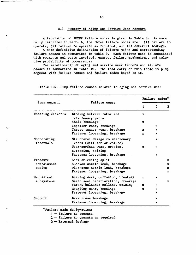
45
8.3 Summary of Aging and Service Wear Factors
A tabulation of AUXFP failure modes is given in Table 8. As morefully described in Sect. 6, the three failure modes are: (1) failure tooperate, (2) failure to operate as required, and (3) external leakage.
A more definitive delineation of failure modes and correspondingfailure causes is summarized in Table 9. Each failure mode is associatedwith segments and parts involved, causes, failure mechanisms, and rela-tive probability of occurrence.
The relationship of aging and service wear factors and failurecauses is summarized in Table 10. The lead entry of this table is pumpsegment with failure causes and failure modes keyed to it.
Table 10. Pump failure causes related to aging and service wear
Failure modesaPump segment Failure cause
1 2 3
Rotating elements Binding between rotor and x
stationary partsShaft breakage xImpeller wear, breakage xThrust runner wear, breakage x xFastener loosening, breakage x x
Nonrotating Structural damage to stationary xinternals vanes (diffuser or volute)
Wear-surface wear, erosion, x xcorrosion, seizingFastener loosening, breakage x
Pressure Leak at casing split xcontainment Suction nozzle leak, breakage xcasing Discharge nozzle leak, breakage x
Fastener loosening, breakage x
Mechanical Bearing wear, corrosion, breakage x xsubsystems Shaft seal deterioration, breakage x
Thrust balancer galling, seizing x xCoupling wear, breakage x xFastener loosening, breakage x
Support Base frame breakage xFastener loosening, breakage x
aFailure mode designation:1 - Failure to operate2 - Failure to operate as required3 - External leakage

46
Currently used methods for AUXFP failure detections are listed inTable 11. Essentially, this simple table relates failure modes and meansof detection.
Table 11. Methods currently used to detectAUXFP failure modes
Failure mode Means of identification
Failure to operate Visual observationPressure readings at flow-measuring orificePump driver current and voltage or steamflow measurement
Failure to operate Pressure readings at flow-measuring orificeas required Measurements of key parameters, that is,
vibration, temperature, rotational speed,and flow
External leakage Visual
Table 12 summarizes the methods for differentiating between the dif-ferent failure causes. Here, the failure mode is the main entry parame-ter with pump segments, failure causes, and differentiation methods keyedto it.
Table 13 lists the various measurable parameters. Here again, themain entry parameter is failure mode, with pump segments, failure causes,and measurable parameters keyed to it.
Table 14 is a major summary that condenses all key information onAUXFP part failure assessments, including parts, materials, significantstressors, failure causes, and measurable parameters.
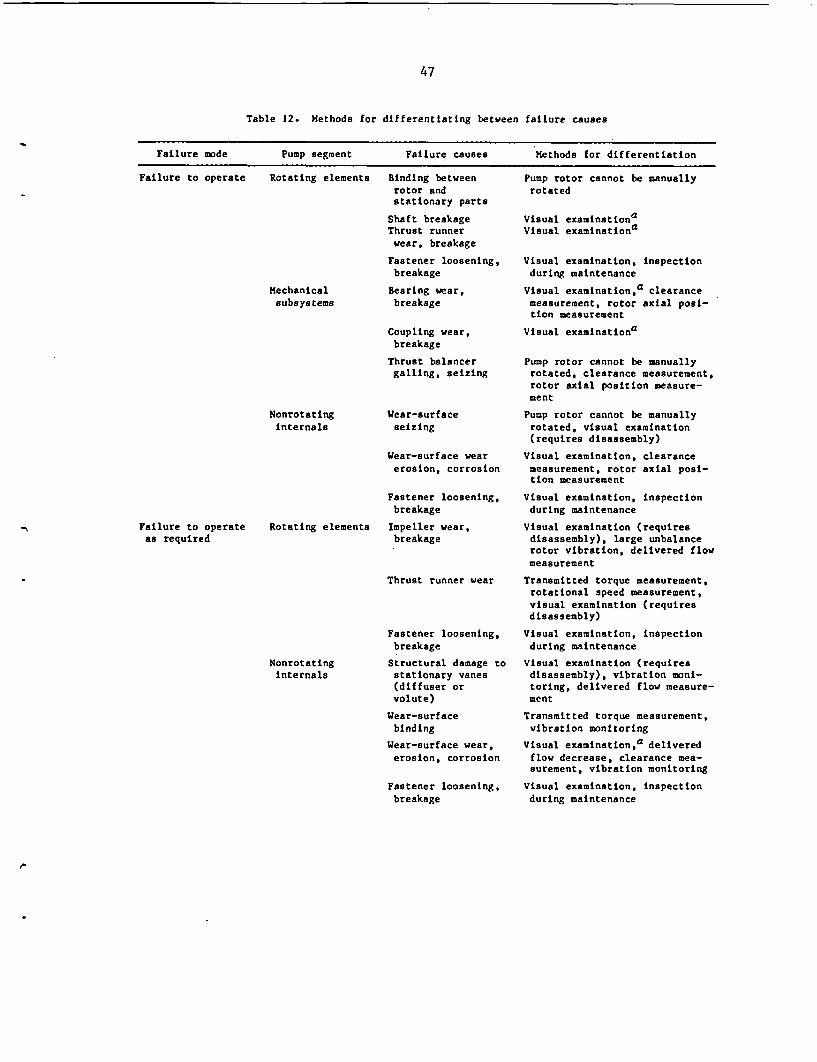
47
Table 12. Methods for differentiating between failure causes
Failure mode Pump segment Failure causes Methods for differentiation
Failure to operate Rotating elements Binding betweenrotor andstationary parts
Shaft breakageThrust runnerwear, breakage
Fastener loosening,breakage
Bearing wear,breakage
Mechanicalsubsystems
Coupling wear,breakage
Thrust balancergalling, seizing
NonrotatingInternals
Wear-surfaceseizing
Wear-surface wearerosion, corrosion
Fastener loosening,breakage
Impeller wear,breakage
Pump rotor cannot be manuallyrotated
Visual examinationaVisual examinationa
Visual examination, inspectionduring maintenance
Visual examinationa clearancemeasurement, rotor axial posi-tion measurement
Visual examinationa
Pump rotor cannot be manuallyrotated, clearance measurement,rotor axial position measure-ment
Pump rotor cannot be manuallyrotated, visual examination(requires disassembly)
Visual examination, clearancemeasurement, rotor axial posi-tion measurement
Visual examination, inspectionduring maintenance
Visual examination (requiresdisassembly), large unbalancerotor vibration, delivered flowmeasurement
Transmitted torque measurement,rotational speed measurement,visual examination (requiresdisassembly)
Visual examination, inspectionduring maintenance
Visual examination (requiresdisassembly), vibration moni-toring, delivered flow measure-ment
Transmitted torque measurement,vibration monitoring
Visual examinationa deliveredflow decrease, clearance mea-surement, vibration monitoring
Visual examination, inspectionduring maintenance
Failure to operateas required
Rotating elements
NonrotatingInternals
Thrust runner wear
Fastener loosening,breakage
Structural damage tostationary vanes(diffuser orvolute)
Wear-surfacebinding
Wear-surface wear,erosion, corrosion
Fastener loosening,breakage
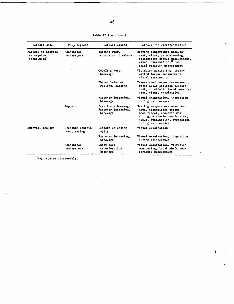
48
Table 12 (continued)
Failure mode Pump segment Failure causes Methods for differentiation
Failure to operate Mechanical Bearing wear, Bearing temperature measure-as required subsystems corrosion, breakage ment, vibration monitoring,(continued) transmitted torque measurement,
visual examinationsd rotoraxial position measurement
Coupling wear, Vibration monitoring, trans-breakage mitted torque measurement,
visual examination
Thrust balancer Transmitted torque measurement,galling, seizing rotor axial position measure-
ment, rotational speed measure-ment, visual examinationa
Fastener loosening, Visual examination, inspectionbreakage during maintenance
Support Base frame breakage Bearing temperature measure-Fastener loosening, ment, transmitted torquebreakage measurement, acoustic moni-
toring, vibration monitoring,visual examination, inspectionduring maintenance
External leakage Pressure contain- Leakage at casing Visual examinationment casing split
Fastener loosening, Visual examination, inspectionbreakage during maintenance
Mechanical Shaft seal Visual examination, vibrationsubsystems deterioration, monitoring, local shaft tem-
breakage perature measurement
aMay require disassembly.
I

-
49
Table 13. Measurable parameters
Failure mode Pump segment Failure causes Measurable parameters
Failure to operate Rotating elements
Mechanicalsubsystems
Nonrotatinginternals
Failure to operateas required
Rotating elements
Nonrotatinginternals
Mechanicalsubsystems
Support
Binding betweenrotor andstationary parts
Shaft breakage
Thrust runnerwear, breakage
Fastener loosening,breakage
Bearing wear,breakage
Coupling wear,breakage
Thrust balancergalling, seizing
Wear-surface seiz-ing
Wear-surface wear,erosion, corrosion
Fastener loosening,breakage
Impeller wear,breakage
Thrust runnerwear
Fastener loosening,breakage
Structural damageto stationary vanes(diffuser or volute)
Wear-surface bind-Ing
Wear-surface wear,erosion, corrosion,
Fastener looseningbreakage
Bearing wear,corrosion, breakage
Coupling wear,breakage
Thrust balancergalling, seizing
Fastener looseningbreakage
Base frame breakageFastener loosening,breakage
Leakage at casingsplit
Fastener loosening,breakage
Shaft sealdeterioration,breakage
Appearance (heat checking,welding)
Appearance
Appearance, clearance
Appearance, bolt torque
Appearance, clearance, rotoraxial position
Appearance
Appearance, clearance, rotoraxial position
Appearance, clearance
Appearance, clearance, rotoraxial position
Appearance, bolt torque
Appearance, rotor vibration,delivered flow
Transmitted torque, rotationalspeed, appearance
Appearance, bolt torque
Delivered flow,appearance, vibration
Transmitted torque,vibration
Appearance, deliveredflow, clearance, vibration
Appearance, bolt torque
Temperature, rotor vibration,transmitted torque, appearance,rotor axial position
Vibration, transmitted torque,appearance
Transmitted torque, rotor axialposition, rotational speed,appearance
Appearance, bolt torque
Bearing temperature, trans-mitted torque, noise, vibra-tion, appearance, bolt torque
Leakage rate
Appearance, torque
Seal leakage rate,rotor vibration,local shaft temperature
External leakage Pressure contain-ment casing
Mechanicalsubsystems
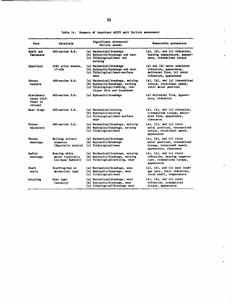
50
Table 14. Summary of important AUIXFP part failure assessment
Part Materials Significnt strfirorh/ Measurable parameters
Shaft and 400-series B.S. (a) Mechanical/breakagefasteners
Impellers CrNi alloy steels,17-4Ph
(b) Hydraulic/breakage and wear(c) Tribological/wear and
seizing
(a) Mechanical/breakage(b) Hydraulic/breakage and wear(c) Tribological/wear-surface
wear
(a) Mechanical/breakage, seizing(b) Hydraulic/breakage, seizing(c) Tribological/rubbing, lub-
ricant dirt and breakdown
(a) Hydraulic/breakage
Thrustrunners
Stationaryvanes (dif-fuser orvolute)
Wear rings
Thrustbalancers
Thrustbearings
400-series B.S.
400-series S.S.
400-series S.S.
400-series S.S.
Rolling contactelements(Specialty steels)
(a)(b)(c)
(a)(b)(c)
(a)(b)(c)
Mechanical/seizingHydraulic/seizingTribological/wear-surfacewear
Mechanical/breakage, seizingHydraulic/breakage, seizingTribological/wear
Mechanical/breakageHydraulic/breakageTribological/wear
(a), (b), and (c) vibration,bearing temperature, appear-ance, transmitted torque
(a) and (b) rotor unbalancevibration, appearance,delivered flow; (c) rotorvibration, appearance
(a), (b), and (c) transmittedtorque, rotational speed,rotor axial position
(a) delivered flow, appear-ance, vibration
(a), (b), and (c) vibration,transmitted torque, deliv-ered flow, appearance,clearance
(a), (b), and (c) rotoraxial position, transmittedtorque, rotational speed.appearance
(a), (b), and (c) rotoraxial position, transmittedtorque, rotational speed,appearance, clearance
(a), (b), and (c) rotorvibration, bearing tempera-ture, transmitted torque,appearance
(a), (b), and (c) seal leak-age rate, rotor vibration,local shaft, temperature
(a), (b), and (c) rotorvibration, transmittedtorque, appearance
Radialbearings
Shaftseals
Bearing whitemetal (typicallytin-base babbitt)
Stuffing-box ormechanical type
(a)(b)(c)
(a)(b)(c)
(a)(b)(c)
Mechanical/breakage, seizingHydraulic/breakage, seizingTribological/seizing, wear
Mechanical/breakage, wearHydraulic/breakage, wearTribological/wear
Mechanical/breakage, wearHydraulic/breakage, wearTribological/breakage wear
Coupling Gear type(usually)

51
9. SUMMARY AND RECOMMENDATIONS
9.1 Summary
AUXFPs are critically-important safety-related equipment.; Severaldesign, operation, maintenance, and condition-monitoring factors of thesepumps warrant investigation. For example, as detailed in Sect. 2.4,tighter specification of certain materials of construction and fabrica-tion methods could potentially provide marked improvements in AUXFP dura-bility and thus higher reliability.
As described in Sect. 6.3, present HHPS multistage centrifugal pumpssuffer from years of dormant engineering research and development effortsin the United States. For example, bearing and thrust balancer designsmay in some cases be based on marginally reliable definitions of thestatic and dynamic rotor loads produced by the complex fluid flow phenom-ena that occur within such pumps. Engineering test data of specific pumpconfigurations over the full range of operating conditions and possiblelevels of wear are not always available to designers because such testingis not always performed on every-specific configuration. This has oftenresulted in undersized and marginal load carrying components in similarpumps used in other (non-AUXFP) applications.
As described in Sect. 6.3.1, the question of a prudent bypass flowcapacity (to minimize dynamic loads and vibration), which varies fromdesign to design, needs to be further studied and clarified.
AUXFPs are now typically installed with virtually no monitoringdevices for establishing data trends nor secondary bypass flow loops thatwould facilitate periodic regular testing over the full-flow ranges nec-essary to simulate the various emergency pumping scenarios. Also, thereis presently no standardized requirement for scheduled disassembly andintensive pump internal inspection (as proposed in Sect. 7.2.3 anddetailed in Sect. 8.1).
In response to these important considerations, the following obser-vations are made.
9.1.1 Bypass flow criteria
Present practice should be reviewed with the intent of determiningif present bypass flow rates are a significant contributor to wear andaging factors.
9.1.2 Secondary bypass flow test loop
Present practice should be reviewed with the inteit of determiningthe degree of need for in-plant full-flow test loops to simulate thevarious emergency pumping scenarios. Such loops would permit the pump tobe regularly "exercised" at typical emergency condition flow rates,rather than the potentially abusive bypass flow rates of most present in-stallations. This would also permit performance monitoring and trendestablishment at realistic operating conditions.

52
9.1.3 Monitoring and establishing trends
State-of-the-art monitoring capability should be studied in regardto its value in assessing wear and aging factors in AUXFPs. Monitoringfactors to be studied should include at least the following: (1) orbitalrotor vibration, (2) bearing temperature and noise, (3) rotor axial posi-tion, and (4) delivered head-capacity performance. Trends in this moni-tored information should be studied and correlations with wear and agingfactors sought. Details of these topics are covered in Sect. 8.2.
9.1.4 Scheduled disassembly and detailed inspection
Periodic disassembly and detailed inspection of AUXFPs are necessi-ties. The proposed inspection and component renewal factors are outlinedin Sect. 7.2.3 and discussed in Sect. 8.1. The most likely time forthese functions to be performed would be during each refueling period.
9.1.5 Pump specifications
It is recommended that, when new pumps are purchased, specificationsbe written to take advantage of the latest proven advances in pump design.Results from projects such as those being carried out by the EPRI2 can behelpful in preparing such specifications.
9.2 Recommendations
It is recommended that the appropriateness and utility of the sur-veillance and monitoring methods described in this report be examined inthe next phase of the investigation on AUXFPs. The measurable parame-ters identified also are to be evaluated in terms of effectiveness foruse in detecting degradation and establishing degradation trends.
The relationship of the first-phase study to the NPAR Programstrategy is illustrated by the cross-hatched part of Fig. 4.

0RN'L-DWG. 86-4226 ETD
PN.ctuco. Cost ah inth Code0
Kft.lnIdg P.,fo...ane. St.dy Sto.dawdsKr~~~~owt~~~~~dq. - I In~~~~~~~~~dicaows co~~ 00001 4
to.$~~~~o
5.rv.ce .1
I N.~~~~~~~~~~~~~~~~~
Fig. 4. NPAR program strategy.

54
REFERENCES
1. U.S. Nuclear Regulatory Commission, Nuclear Plant Aging ResearchWPAR) Program Plan, NUREG-1144, Oak Ridge Natl. Lab., July 1985.
2. Electric Power Research Institute, "Feed Pump Hydraulic Performanceand Design Improvements," Research Project RP1884-10 (ongoing).
S3I8V88i1 SJ'IN

55
BIBLIOGRAPHY*
t1. E. Makay and 0. Szamody, Survey of Feed Pump Outages, EPRI FP-754,Electric Power Research Institute, April 1978.
*2. E. Makay and M. L. Adams, Operation and Design Evaluation of MainCoolant Pumps for PWR and BWR Service, EPRI NP-1194, Electric PowerResearch Institute, September 1979.
*3. E. Makay and 0. Szamody, Recommended Design Guidelines for Feed-water Pumps in Large Power Generating Units, EPRI CS-1512, ElectricPower Research Institute, September 1980.
*4. M. L. Adams and E. Makay, Development of Advanced Rotor-BearingSystems for Feedwater Pumps, Electric Power Research Institute,Phase-1 Final Report, EPRI FP-1274, November 1979; Phase-2 FinalReport, EPRI CS-2027, September 1981; Phase-3 Final Report, EPRICS-3203, July 1983.
t5. E. Makay, "Eliminating Pump Stability Problems," Power, July 1970.
*6. E. Makay, "Design of Fluid Movers," Mach. Des., May 13, 1971.
7. E. Makay and J. E. Hanafee, Failure Analysis of the Monticello Nu-clear Reactor Feed Pumps, F-C3053, Franklin Institute ResearchLaboratories, June 1971.
8. E. Makay, "Failure Analysis of Rotating Machinery in Nuclear andFossil Applications," Power, December 1971.
9. E. Makay and I. Karassik, Failure Analysis of the Trading-houseCreek No. 2 Feedwater Systems, F-C3338, Franklin Institute ResearchLaboratories, May 1972.
10. E. Makay and E. Filetti, Evaluation and Testing of the Reactor FeedPumps for the Dresden Nuclear Station, F-C3262, Franklin InstituteResearch Laboratories, April 1972. Prepared for ConsolidatedEdison Co.
11. E. Makay, Failure Analysis and Design Corrections of the MonroeStation 50% Capacity Boiler Feed Pumps, F-C3380, Franklin InstituteResearch Laboratories, July 1972.
12. E. Makay, Evaluation of Field Testing and Redesign of the Zion Nu-clear Feed Pumps, F-C3375-03, Franklin Institute Research Labora-tories, October 1972.
*Those publications marked with a single or double dagger are sug-gested as the most readable and informative for the nonexpert. Thosewith a single dagger are considered essential reading.
56
13. E. Makay and G. E. Drechsler, "Trouble-Shooting Large Pumps for Nu-clear and Fossil Central Stations," Power, December 1973.
14. E. Makay, Failure Analysis and Field Testing of Feed Pumps andFeedwater Piping System at the Prairie Island Nuclear Station,ERCO-7415-01, Energy Research and Consultants Corp., March 1974.
t15. E. Makay and J. Saez, "High Pressure Boiler Feed Pump TroublesClear Up After Balance Disk Changes," Power, June 1974.
16. E. Makay, "Stability of Centrifugal Pump Rotor Systems," Trans.ASME J. Ind., 1081-84, August 1974.
17. E. Makay, Failure Analysis of the Feedwater Pumps at the PrairieIsland Nuclear Generating Station, ERCO-7415-02, Energy Researchand Consultants Corp.
*18. E. Makay, "Hydraulic Problems in Nuclear Feed Pumps Demand Atten-tion to Cut Costly Downtime," Power, March 1975.
19. E. Makay, Failure Analysis of the Biblis (Germany) Nuclear FeedPumps, ERCO-7522, Energy Research and Consultants Corp., May 1975.
20. E. Makay and 0. Szamody, Testing and Evaluation of the Stand-byAuxiliary Feed Pumps at the Ginna PWR Nuclear Station, ERCO-7734-01,Energy Research and Consultants Corp., July 1977.
21. E. Makay, Instabilities Caused Nuclear Generating Station Trips,Transients and System Upsets Related to the Feedwater System of PWRand BWR Nuclear Units, EPRI 77-109, Electric Power Research Insti-tute, October 1977.
22. E. Makay, Testing and Evaluation of the Auxiliary Feed Pumps forthe Farley Nuclear Generating Station, ERCO-7805-1, Energy Researchand Consultants Corp.
t23. E. Makay, "Better Understanding of Nuclear and Fossil Feed PumpDamage," Power, June 1979.
24. E. Makay, Centrifugal Pump Hydraulic Investigation Classified By:(1) Pump Stage Geometry and (2) Flow Mechanisms, EPRI TPS-78-189-01, Electric Power Research Institute, July 1979.
25. E. Makay, Evaluation of Pump Failure Modes at the Susquehanna Nu-clear Station, Report 10503, Energy Research and Consultants Corp.,December 1980.
*26. E. Makay, "How Close Are Your Feed Pumps to Instability-CausedDisaster?" Power, December 1980.
t27. E. Makay, "Enlarge Radial Gap in Feed Pumps," Power, March 1981.
57
*28. M. L. Adams and E. Makay, "How to Apply Pivoted-Pad Journal Bear-ings," Power, October 1981.
29. E. Makay, Major Feed Pump Reliability and Efficiency Improvementsand Reduction in Maintenance Through Minor Hardware Modifications,EPRI RP 1884-3, Electric Power Research Institute.
30. E. Makay and I. Diaz-Tous, "Performance Improvement of Boiler FeedPump Axial Balancing Devices," Proceedings EPRI Symposium on Feed-water Pumps, June 1982.
t3l. E. Makay and D. Nass, "Gap-Narrowing Rings Make Booster Pumps Quietat Low Flow," Power, September 1982.
t3 2. E. Makay and J. A. Barrett, "Changes in Hydraulic Component Geome-tries Greatly Increased Power Plant Availability and Reduced Main-tenance Costs: Case Histories," Proceedings First InternationalPump Symposium, Texas AMM University, May 1984.
33. E. Makay, Performance Behavior of the Auxiliary Feedwater Pumps inthe Normal and Extreme Run-Out Operating Modes, Palo Verde NuclearPower Plant, ERCO-10,756, Energy Research and Consultants Corp.,March 1985.
34. Hydraulic Institute Standards, 14th Edition, 1983.
35. American Petroleum Institute (API) Standard 610, "Centrifugal Pumpsfor General Refinery Services," 6th Ed., January 1981.
36. M. L. Adams and J. Padovan, "Insights into Linearized Rotor Dy-namics," J. Sound Vib. 76(1), 1981.
37. M. L. Adams, "Nonlinear Dynamics of Flexible Multi-Bearing Rotors,"J. Sound Vib. 71(1), 1980.
38. M. L. Adams, E. Makay, and J. P. Dimmer, "Increasing Feed Pump Re-liability," Proceedings, 1980 Reliability Conference for the Ezec-tric Utility Industry.
39. M. L. Adams, E. Makay, and J. P. Dimmer, "Feed Pump VibrationResearch - Interstage Fluid Annuli," ASME Paper No. 80-JPGC/Pwr-20.
40. M. L. Adams, "An Introduction to Rotor Dynamics," Mach. Des.,August 1972.
41. M. L. Adams, "Keep Rotor Vibration Under Control," Power, August1978.
42. M. L. Adams, ed., Proceedings of Symposium on Rotor Dynamical In-stability, ASME Book No. AND Vol. 55, ASME Applied Mechanics Divi-sion, June 1983.

58
43. S. E. Pace, Project Manager, Feed Pump Hydrautic Performance andDesign Improvements, Research Project RP1884-10, Electric Power Re-search Institute (ongoing).

59
*Appendix A
SUMMARY OF ASME BOILER AND PRESSURE VESSEL CODE
SECT. XI REQUIREMENTS
The Sect. XI requirements for pumps are given in Subsection IWP,In-service Testing of Pumps in Nuclear Power Plants. This subsectiondiscusses in-service testing of Class 1, 2, and 3 pumps required toachieve the cold shutdown condition for a reactor or to mitigate theconsequences of an accident.
The in-service testing procedure given in Paragraph IWP-3100 is asfollows:
"An in-service test shall be conducted with the pump oper-ating at nominal motor nameplate speed for constant speed drivesand at a speed adjusted to the reference speed for variablespeed drives. The resistance of the system shall be varieduntil either the measured differential pressure or the measuredflow rate equals the corresponding reference value. The testquantities shown in Table IWP-3100-1 shall then be measured orobserved and recorded as directed in this Subsection. Each mea-sured test quantity shall then be compared with the referencevalue of the same quantity. Any deviations determined shall becompared with the limits given in Table IWP-3100-2 and thespecified corrective action taken."
*Work performed by G. A. Murphy, ORNL Nuclear Operations AnalysisCenter.
Table IWP-3100-1. In-service test quantities
Quantity Measure Observe
Speed N (if variable speed) V
Inlet pressure Pi la
Differential pressure AP v
Flow rate Q V
Vibration amplitude V V
Proper lubricant level or pressure V
Bearing temperature Tb
aMeasure before pump startup and during test.Source: ASME Boiler and Pressure Vessel Code, Sect. XI,IWP, p. 209 (1983).
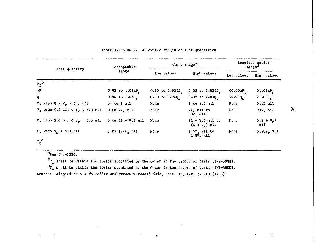
Table IWP-3100-2. Allowable ranges of test quantities
Alert rangea ~Required actionTest quantity Acceptable Alert rangea range
Low values High values Low values High values
Pib
AP 0.93 to 1.02APr 0.90 to 0.93APr 1.02 to 1.03APr <0.90aPr >1.03 APr
Q 0.94 to 1.02Qr 0.90 to 0 .94Qr 1.02 to 1 . 0 3 Qr <0 9OQr >1.03Qr
V, when 0 4 Vr 4 0.5 nil 0. to I nil None I to 1.5 mil None >1.5 mil
V, when 0.5 ail < Vr c 2.0 ail 0 to 2Vr mil None 2Vr mil to None >3Vr mil3vr nil
V, when 2.0 mil < Vr < 5.0 mil 0 to (2 + Vr) nil None (2 + Vr) mil to None >(4 + Vd)(4 + Vr) ail mil
V, when Vr > 5.0 mil 0 to 1.4Vr mil None 1.4Vr mil to None >1*8vr Mil1.8Vr Mil
TbC
aSee IWP-3230.
bpi shall be within the limits specified by the Owner in the record of tests (IWP-6000).
CTb shall be within the limits specified by the Owner in the record of tests (IWP-6000).
Source: Adapted from ASME Boiler and Pressure Vessel Code, Sect. XI, IWP, p. 210 (1983).
An0
61
Paragraph IPW-3110 states the following:
"Reference values are defined as one or more fixed sets ofvalues of the quantities shown in Table IWP-3100-1 as measuredor observed when the equipment is known to be operating accept-ably. All subsequent test results shall be compared to thesereference values or with new reference values established inaccordance with IWP-3111 and IWP-3112. Reference values shallbe determined from the results of the first in-service test runduring power operation. Reference values shall be at points ofoperation readily duplicated during subsequent in-service test-ing."
Corrective action is given in Paragraph IWP-3230 as follows:
a. If deviations fall within the Alert Range of TableIWP-3100-2, the frequency of testing specified in IWP-3400 shallbe doubled until the cause of the deviation is determined andthe condition corrected.
"b. If deviations fall within the Required Action Range ofTable IWP-3100-2, the pump shall be declared inoperative and notreturned to service until the cause of the deviation has beendetermined and the condition corrected.
"c. Correction shall be either replacement or repair perIWP-3111, or shall be an analysis to demonstrate that the condi-tion does not impair pump operability and that the pump willstill fulfill its function. A new set of reference values shallbe established after such analysis.
"d. When tests show deviations greater than allowed (seeTable IWP-3100-2), the instruments involved may be recalibratedand the test rerun."
Paragraph IWP-3400 specifies the frequency of in-service tests:
"a. An in-service test shall be run on each pump nominallyevery three months during normal plant operation. It is recom-mended that this test frequency be maintained during shutdownperiod if this can reasonably be accomplished, although this isnot mandatory. If it is not tested during plant shutdown, thepump shall be tested within one week after the plant is returnedto normal operation.
"b. Pumps that are operated more frequently than everythree months need not be run or stopped for a special test, pro-vided the plant log shows each such pump was operated at leastonce every three months at the reference conditions, and thequantities specified were measured, observed, recorded, and an-alyzed."
62
Paragraph IWP-3500 provides the duration of tests:
"a. When measurement of bearing temperature isquired, each pump shall be run at least five minutesditions as stable as the system permits. At the endtime at least one measurement or observation of eachquantities specified shall be made and recorded.
not re-under con-of thisof the
"b. When measurement of bearing temperature is required,each pump shall be run until the bearing temperatures (IWP-4310)stabilize, and then the quantities specified shall be measuredor observed and recorded. A bearing temperature shall be con-sidered stable when three successive readings taken at tenminute intervals do not vary by more than three percent."
63
Appendix B
OPERATING EXPERIENCE DATA BASES AND REPORTS
Failure information obtained from LER, NPRDS, and IPRDS data basesis summarized below.
B.1 Nuclear Operations Analysis Center RECONLicensee Event Reports Data Base Survey
Abstracts of all LERs and reports issued prior to LERs by U.S.utilities are stored on the Nuclear Operations Analysis Center data basethat can be accessed through the DOE RECON system'. A search was made ofthis data base for all events indexed as auxiliary or emergency feedwaterpumps. Each 100-word abstract was reviewed to determine (1) the mode offailure, (2) the mode of detection, (3) the maintenance activity, and(4) the cause of failure.
This review found 53 events out of a total of 1139 events involvingAUXFPs during the time period 1973-1983. Results are summarized in TableB.1.
During the review of the 1139 events certain types of failures werenoted that were excluded from this study: (1) failure to test; (2) obvi-ous design errors including seismic analysis; (3) obvious operator errors;(4) failure of the pump driver (motor, turbine, diesel generator, etc.);(5) failure of a valve in the system; and (6) failure of instruments orcontrols. Only failures of the pump itself are included in Table B.1.
Bearing, packing, and seals are the primary failedjparts. Failuresof shafts, impellers, internals, and housings appear to be isolated cases.Forty-two percent of all failures were detected during testing of theequipment, while 29% were detected during pump operation. A few problems(6%) were identified during maintenance action.
Sixty-seven percent of the maintenance action was replacement orrepair of damaged or worn subcomponents. In 6% of the events a modifica-tion was made to correct the deficiency. The major failure cause wasinsufficient or improper cooling or lubrication (23%). Improper mainte-nance accounted for 17%, while wear was the cause in 15% of the events.For 29% of the failures, the cause was either unknown or not stated.
B.2 Nuclear Plant Reliability Data System
The NPRDS data base was searched for AUXFP failures. Table B.2 is asummary of the results that contains the failure information derived fromcodes specified by the utilities. 'Out of a total of 70 events-found, 14were actual failures of the pump itself. In cases where more than one
*Work performed by G. A. Murphy, ORNL Nuclear Operations AnalysisCenter.

64
Table B.1. Summary of AUXFP-typefailures reported in LERs
(1973-1983)
Item Ratea
Failed component
Bearings 48Packing and seal 30Casing 4Internal components 4Impeller 2Capacity 2Shaft 2Other 8
Methods of detection
Testing 42Operation 29Maintenance 6Not stated 23
Maintenance action
Replacement 67Repair 25Modification 6No repair required 2
Identified cause
Lack of lubrication or 23cooling
Maintenance error 17Wear/end of life 15Design error 6Crud 4Operator error 2Other 4Not stated 19Unknown 10
aTotal of 53 events.

65
Table B.2. AUXFP-type failuresreported in NPRDS data base
(1974-1985)
Item RateaItem ~~~~~(%)
Failed component
Packing/gasket 50Bearings 38Internal components 6Shaft 6
Methods of detection
Incidental observation 33Surveillance testing 25Routine observation 12Audiovisual alarm 12Operational abnormality 12Special inspection 6
Maintenance action
Repair/replace 94Modify 6
Failure cause
Wear 58Lubrication 12Binding 12Aging 12Abnormal stress 6
aTotal of 14 failure reports.
cause code was given, only the first or the one supported by the eventnarrative was used.
The predominant failed subcomponents were pump packingand bearingfailure, with only isolated failures of other subcomponents. Testing orobservation detected most of the failures (88%), with 12% involvingoperational abnormalities.
Repair or replacement of subcomponents was the primary maintenanceaction (94%), with only 6% being modified. Wear was listed as the pri-mary failure cause (58%). Lubrication, binding, and aging were 12% each.
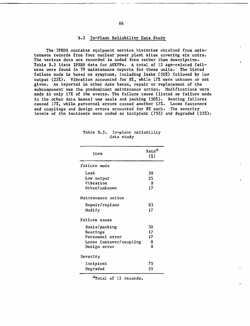
66
B.3 In-Plant Reliability Data Study
The IPRDS contains equipment service histories obtained from main-tenance records from four nuclear power plant sites covering six units.The various data are recorded in coded form rather than descriptive.Table B.3 lists IPRDS data for AUXFPs. A total of 12 age-related fail-ures were found in 79 maintenance reports for these units. The listedfailure mode is based on symptoms, including leaks (50%) followed by lowoutput (25%). Vibration accounted for 8%, while 17% were unknown or notgiven. As reported in other data bases, repair or replacement of thesubcomponent was the predominant maintenance action. Modifications weremade in only 17% of the events. The failure cause (listed as failure modein the other data bases) was seals and packing (50%). Bearing failurescaused 17%, while personnel errors caused another 17%. Loose fastenersand couplings and design errors accounted for 8% each. The severitylevels of the incidents were coded as incipient (75%) and degraded (25%).
Table B.3. In-plant reliabilitydata study
Item Ratea
Failure mode
Leak 50Low output 25Vibration 8Other/unknown 17
Maintenance action
Repair/replace 83Modify 17
Failure cause
Seals/packing 50Bearings 17Personnel error 17Loose fastener/coupling 8Design error 8
Severity
Incipient 75Degraded 25
aTotal of 12 records.

67
Appendix C
AUTOMATIC TRIPPING AND FAILURE
An overspeed trip on turbine-driven AUXFPs gives the one automatictripping action that is built into all turbine-driven AUXFPs. However,overspeed tripping at startup has been a problem. The cause (and thusavailable fixes) of this problem is well understood by operating person-nel at some plants.
One recommendation by the major governor supplier is the addition ofa separate oil-pressurizing pump for the governor, which comes on priorto the steam-valve-open action. Plant engineers are not favorable tothis proposal because it involves an additional pump with additionalpotential reliability and maintenance problems. In at least one plant(Palo Verde), the corrective fix was to install an additional steam line(1 in.) to the drive turbine that is used for the initial part of startupand is opened before the main steam inlet valve is opened. This approachallows the speed control governor time to gain control of the situationand to achieve the operating speed without such a large overshoot as tooverspeed trip the machine.
69
Appendix D
ENGINEERING INFORMATION RELEVANT TO AUXFP RELIABILITY
D.1 Introduction
Since the March 1979 TMI incident, considerable attention andscrutiny has been focused on auxiliary feedwater systems by the NRC andindustry groups. This process is still in the phase of fact-finding,assessment, and determination of what industry-wide measures are requiredto ensure the high reliability appropriate to safety-related systems andequipment. AUXFPs are critically important safety-related components.Therefore, to provide further insight into the pertinent engineeringareas, the following sections of this appendix present selected technicalbackground information critical to high-head-per-stage centrifugal pumps.
D.2 Pump Hydraulic Instability
"Hydraulic instability" is now the term most commonly used in thecentrifugal pump field to label the highly active unsteady flow phenomenathat become progressively more pronounced the farther away from best-efficiency flow that a pump is operated. As clearly identified through-out the main body of this document, these unsteady flows are the mostsignificant contributor to deterioration (i.e., aging and wear) of pumpcomponents because of the high-amplitude dynamic forces that they pro-duce. In main feedwater systems, these unsteady flow phenomena also fre-quently produce hard-to-control conditions in the feedwater system, lead-ing to transients, trips, and upset conditions.
Figure D.1 shows delineation of stable and unstable flow regimes forvarious classes (i.e., different specific speeds) of power plant pumps.It is based on a composite of field troubleshooting experience, shoptests, and laboratory tests; it represents what current hydraulic designtechnology can typically provide. Current EPRI-sponsored researchaddresses this area of feed pump design technology.
Hydraulic instability has also been characterized by the label in-ternal "flow recirculation," which occurs both at the inlet and dischargeregions of a pump stage at off-design operating flows. These flow recir-culation cells, as illustrated in Figs. D.2 and D.3, are highly unsteady,giving rise to large vibration excitation forces and hard-to-control flowpulsations in the entire pump loop. Figure D.4 illustrates the ramifica-tion of hydraulic instability with regard to the head-capacity character-istic of a pump. Figure D.4 shows how different pumps, all satisfyingthe same best-efficiency flow condition, can have a significantly differ-ent quality of hydraulic performance at off-design operating flows.
Figure D.5 shows how the vane-passing shock intensity increases withsmaller impeller-diffuser vane tip clearance.
The feedwater pump is also an active element in the overall feed-water flow loop. Thus, proper analysis of pump system stability problemsrequires the complete feedwater loop to be treated as a connected system.

70
ORNL-DWG. 86-4227 ETO
10
Cn
U)
z
U)
co0
zC]z0
a-U)4IL
0~U)
2
L _.0 25 50 75 100
PUMP FLOW, % OF RATED
Fig. D.1. Anticipated useful operating ranges for pumps used inlarge nuclear and fossil power generating units. (Inner line of designmargin area is preferred; if hydraulic instability occurs at higher flowsvarious pump and system problems can be expected.) Source: E. Makay and0. Szamody, Survey of Feed Pump Outages, EPRI FP-754, Electric PowerResearch Institute, April 1978.
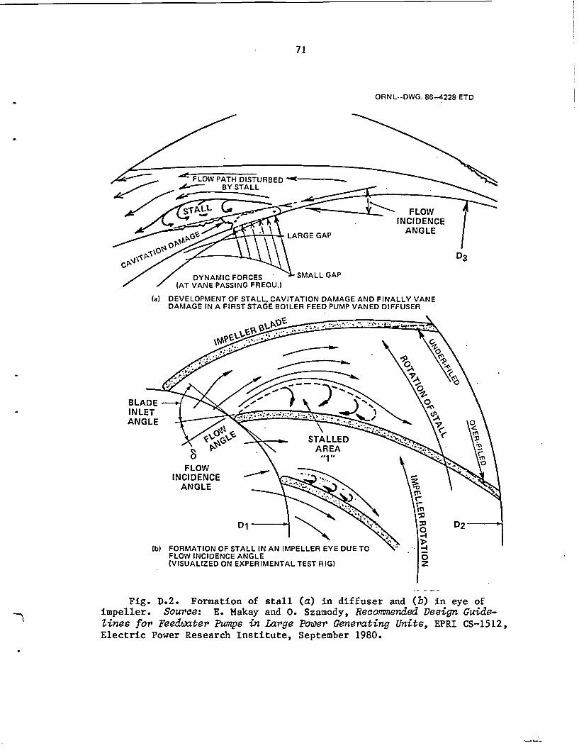
71
ORNL--DWG. 86-4228 ETD
DYNAMIC FORCES(AT VANE PASSING FREOU.)
(a) DEVELOPMENT OF STALL, CAVITATION DAMAGE AND FINALLY VANEDAMAGE IN A FIRST STAGE BOILER FEED PUMP VANED DIFFUSER
BLADEINLETANGLE
FORMATION OF STALL IN AN IMPELLER EYE DUE TOFLOW INCIDENCE ANGLE(VISUALIZED ON EXPERIMENTAL TEST RIG)
Fig. D.2. Formation of stallimpeller. Source: E. Makay and 0.Zines for Feedwater Pumps in LargeElectric Power Research Institute,
(a) in diffuser and (b) in eye ofSzamody, Recommended Design Guide-Power Generating Units, EPRI CS-1512,September 1980.
._ 4_ .

- -- -
72
ORNL-DWG. 86-4229 ETD
Ae /~~~<)~~~~~t (S~~~~~~~~;~
ZI
LU 1-11 70F��
f~~~~~~~~
Fig. D.3. Secondary flow pattern in and around pump impeller stageat off-design flow operation. Source: E. Makay and 0. Szamody, Surveyof Feed Pump Outages, EPRI FP-754, Electric Power Research Institute,April 1978.

73
ORNL-DWG. 86-4230 ETD
125
0
I
C-
* 50
% BEST EFFICIENCY FLOW
Fig. D.4. Head-capacity characteristics of multistage boiler feedpumps. Curve "A" is correct and desired for stable system operation.Curve "B" represents hydraulically unstable impeller-diffuser design.Parallel- as well as single-pump operation is difficult in the unstableflow regime. Curve "C" shows design with flat head curve at part loadresulting in control system malfunctioning. Single-pump operation ispossible in unstable regime. Designs "B" and "C" are not acceptable forutility applications. Source: .E. Makay and 0. Szamody, Survey of FeedPump Outages, EPRI FP-754, Electric Power Research Institute, April 1978.
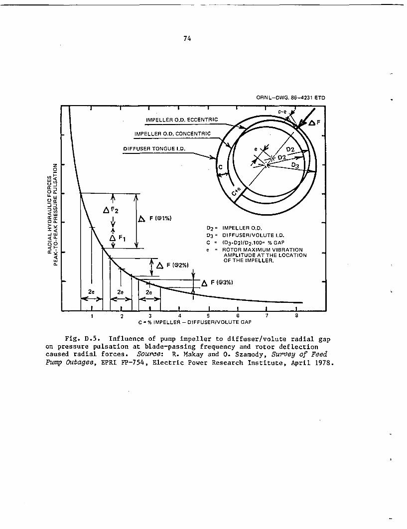
74
ORNL-DWG. 86-4231 ETD
z0
cc 0-w
Uo.
:1 <DJ w- In00
<a.
1 2 3 4 5 6 7 8C = % IMPELLER -DIFFUSER/VOLUTE GAP
Fig. D.5. Influence of pump impeller to diffuser/volute radial gapon pressure pulsation at blade-passing frequency and rotor deflectioncaused radial forces. Source: R. Makay and 0. Szamody, Survey of FeedPump Outages, EPRI FP-754, Electric Power Research Institute, April 1978.
75
Laboratory tests' are now being conducted to determine the transfermatrix of pump stages for imbedding into a total system stabilityanalysis.
D.3 Rotor Vibration
As described earlier, strong hydraulic forces at off-design flowsare one major source of pump vibration. Other significant sources, in-clude rotor unbalance, resonance, rotor-bearing instability (oil whip),internal rubbing, misalignment, coupling, and combinations of these. Theuse of spectrum analyzers has been an invaluable tool in diagnosing andcorrecting various pump vibration problems in the field. Through exten-sive field troubleshooting experience and related redesign work on high-pressure pumps, Fig. D.6 has been assembled to aid in isolating thefundamental cause(s) of excessive pump vibration. Figure D.6 uses pumpflow as the independent parameter and is supplemented by Fig. D.7, whichuses rotational speed as the independent parameter.
Rotor vibration levels, as usually measured at the bearing journals,can be evaluated as being acceptable or unacceptable, based on longexperience of what various types of machinery can comfortably endurethroughout the equipment's usable lifetime. Figure D.8 is typical ofsuch guidelines used throughout the industry in assessing, from monitoredvibration, whether the vibration levels are acceptably low to be consis-tent with high reliability and acceptable plant life.
D.4 Cavitation and NPSH
Boiler feed pump failures caused by cavitation erosion damage areamong the highest-outage-producing pump problems, because cavitation fre-quently causes severe pump internal damage, requiring new internal compo-nents or lengthy factory repair. Cavitation is caused by the productionof very low local pressures adjacent to flow boundaries,.such that vapor-filled pockets form and then collapse violently as they are transportedinto higher pressure regions. Damage is most likely to occur in the inletof the stage but may be carried through the impeller causing erosion ofthe impeller exit or the diffuser (or volute) inlet. Cavitation can becaused by:
1. inadequate NPSH of the feedwater system (i.e., not enough pressureat the pump suction);
2. flow recirculation at the impeller eye while operating in the off-design flow regimes;
3. incorrect hydraulic design of the first-stage impeller (incorrectblade inlet angle);
4. localized high velocities caused by sharp corners and other flowdisturbances such as misplaced inlet guide vanes;
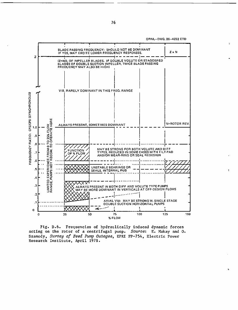
76
ORNL-DWG. 86-4232 ETD
BLADE PASSING FREQUENCY: SHOULD NOT BE DOMINANTIF YES, MAY EXCITE LOWER FREQUENCY RESPONSES. Z x N
_ I iI- - -I- --- -
(Z-NO. OF IMPELLER BLADES. IF DOUBLE VOLUTE OR STAGGEREDBLADES OF DOUBLE SUCTION IMPELLER, TWICE BLADE PASSINGFREQUENCY MAY ALSO BE HIGH)
z
0,
0z0
z
!2
a.
0~
6
zuJn
Li-
VIB. RARELY DOMINANT IN THIS FREO. RANGE
1.01
.9 t
.8
LU
- - 3wu-I-*, c
00-... Fo
0I-W ,;
_.' ,...
* .. ZI-W O
* -EX W
ALWAYS PRESENT,
.7
.6
SOMETIMES DOMINANT IN=ROTOR REV.
FUNCTION /OF% FLOW/
Z22Zi
>0~z
MAY BE STRONG FOR BOTH VOLUTE AND DIFFTYPES, REDUCED IN SOME CASES WITH TILT-PADAND/OR WEAR-RING OR SEAL REDESIGN
UNSTABLE BEARINGS OR _ // 77/SEALS, INTERNAL RUB _ _ _ _ _ _ //
- _ _____ .. :..7..7_.5
.4
.3
.2
.1
0
..W I^ YI . II\ (
iXX - z X AE Z 10<% ALWAYS PRESENT IN BOTH DIFF AND VOLUTE TYPE PUMPS
<_MAY BE MORE DOMINANT IN VERTICALS AT OFF-DESIGN FLOWS
AXIAL VIB: MAY BE STRONG W. SINGLE STAGEDOUBLE SUCTION HORIZONTAL PUMPS
..............~~~ ~~~ ..... _ I
0 25 50 75% FLOW
100 125 150
Fig. D.6. Frequencies of hydraulically induced dynamic forcesacting on the rotor of a centrifugal pump. Source: E. Makay and 0.Szamody, Survey of Feed Pump Outages, EPRI FP-754, Electric PowerResearch Institute, April 1978.
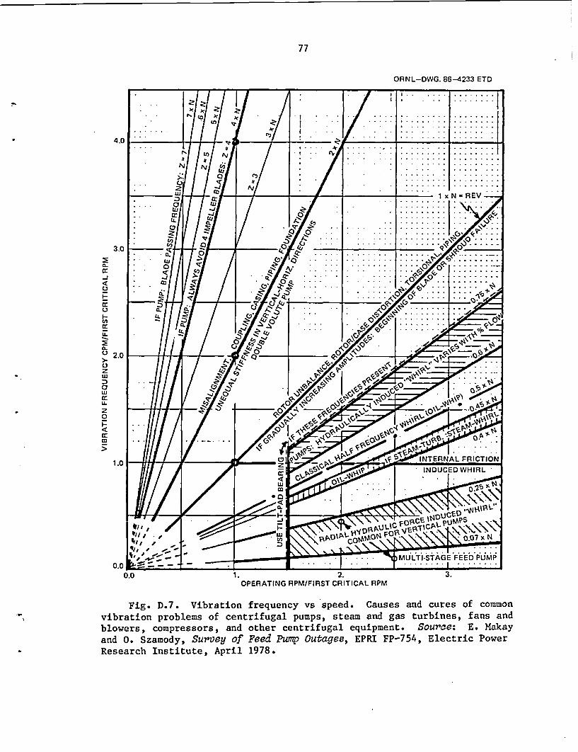
77
ORNL-DWG. 86-4233 ETD
4.
3,
2(.
-j
-(A~crU-
0. 2.1
z
awU-20
1.
* .t ~~~~~~~~~~~~~~~~CO ~~~~~ .. ...I
.Ln ~~~~~~~~~~. .~ .. ..I
.0 .~~~~~~~~~~~~~~~~~~~~~ ......
I ,. 4 ~~~~~~~~~~.. . . . . . . . . . . . . .
* N~
* . . C,' II ~ ~ ~ ~ ~ .. .. .. .. .
______ LU l~~~~~~~~~~~~~1x N =RE V
LU j
~~. 0LU C.. . . .0, . .. . .
6 -.... ...
~~, ). . -S.. . .. ..
CO' ~ ~ O
0 L FRICTION__ __ _ A ',0. C.~~~~rINUCDWHR
0. - .~~~sJ . . *c~~~~fr. .....CY - .'tA6E'F . . .
0.
0.0 1. 2.OPERATING RPM/FIRST CRITICAL RPM
3.
Fig. D.7. Vibration frequency vs speed. Causes and cures of commonvibration problems of centrifugal pumps, steam and gas turbines, fans andblowers, compressors, and other centrifugal equipment. Source: E. Makayand 0. Szamody, Survey of Feed Pump Outages, EPRI FP-754, Electric PowerResearch Institute, April 1978.
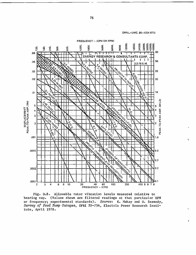
78
ORNL-DWG. 86-4234 ETD
FREQUENCY - (CPM OR RPM)
6 Ci Cs Ci c> ! g ' D O
_ _ N tM Wri~~ ~ .c -~ .c
ci 60 0
C.~ c0 0 0 0 0 0 0 00to 0 0 c" co V occ1 "cocC (a Z - - N Cn IT
_r.08
.05
.03
.02
�. 4-
3101f.9
9kqS I
I
I
I
0.Y I.
�' /;j,
S:�
_Mr--44 I I -I 1\. 13 I I I I \_ .,,, * . t . . .t . . | . . I | I . . . I . .I IuN.
_ \ W
- IX I I 1 " I
%g _T_<to ff 1
IR' I
I i I i I I
EEG I 1\ RESArC &.ENERGY RESEARCH & CONSULTANTS CORP.
hN 1 |2.2478 E.M._ I R<l; I I
'1510I . 11 1 h I
h AOc O
, I'- _Z I I I' +
N -i �0
li11
*4-K!_ _ .
Nnl.\
tW <2z
<0 <
0a 6
Uj
5
4
-\
1.
C.'~
80
50
30
20
1 0
cc-j
|5 E
4 E.
3 he
2 6
I-.
|1.0
, K:j I I I
-1 - +. I Iro.X~~~-s I
\r NL
�.-f-.J-4-+-� P - I �-4 4 � 4 �.- 4 �- 4-4 -4-4-+-4----� 4- + -4-
_4
i
3
2
�*1
-Ir
k I F9I 0
- t-.001 I=:
I I=- I I III I I 1\1 I I H \
-s\ z'- cWv-'. w
- - - -xS I - (ol I
I.* | ! Y�
, _dA I i -
1, XX1- 1 r
I
N
.0005
.0002
nnni
11I I 1 \1 III W
IT I I I I R
N1 I0.3
0.2
N
2 3 4 6 8 10 20 40 60FREQUENCY - (CPS)
100 200 400__I S 0.1, 6 7 8
Fig. D.8. Allowable rotor vibration levels measured relative tobearing cap. (Values shown are filtered readings at that particular RPMor frequency; experimental standards). Source: E. Makay and 0. Szamody,Survey of Peed Pump Outages, EPRI FP-754, Electric Power Research Insti-tute, April 1978.
i
79
5. vortex formation due to obstacles in the flow path, sharp elbows inthe suction piping, incorrect pump inlet geometry, and blunt inletguide vanes; and
6. high-frequency machine vibration can displace water particles per-pendicular to a solid surface creating vapor pockets, thus creatingcavitation (least important type with centrifugal pumps).
Operation of pumps at off-design conditions for extended periods oftime can cause cavitation damage independent of available NPSH, due tohigh-incidence-angle-caused stall and secondary flows like eye recircu-lation as shown in Fig. D.2 and D.3. In a multistage boiler feed pump,impeller cavitation damage usually occurs in the first stage, but it canoccur at other locations where flow conditions satisfy the above require-ments. It is important to distinguish between first-stage impeller cavi-tation and pump internal cavitation; because the'latter is not related topump NPSH. Feed pumps producing high-head/stage are more receptive tocavitation damage because of the higher energy-input densities to thefluid. Velocities and dynamic forces are high enough to accelerate cavi-tation and fatigue damage of pump internal components.
If cavitation damage occurs at design capacity due to insufficientNPSH, usually cavitation damage'can be seen on either or both sides ofthe impeller blade inlet portion. The damage starts at the leading edgeof the vane and may cover a large area. Another type of damage can beobserved on the exposed side of the vane located in the corner where theblade joins the impeller hub. This type of damage indicates a mismatchbetween approach flow and impeller inlet angles that can be caused byextended operation of the pump in the low flow regime, even if NPSH isadequate to prevent cavitation. If severe impeller erosion appears some-what downstream from the vane inlet edge at the periphery of the impellereye, the damage may be caused by inlet flow recirculation (see Fig. D.3).The impeller is then operated in the off-design regime or the impellereye is too large, causing development of flow recirculation at the impel-ler eye. If the damage starts from the vane inlet and is on the nonex-posed side of the vane, then the pump is undersized for the application,that is, operated at substantially larger than best efficiency flow forextended periods of time.
D.5 Pump Internal Clearances
The critical clearances in a high-speed feed pump are those betweenrotating and stationary parts where high-pressure differentials exist(wear-rings of impellers, balancing device cylindrical surfaces, and sealsurfaces) and the gap between impeller periphery and diffuser vanes orvolute tongues. All these clearances affect pump efficiency as well aspump reliability. The closer the clearances, the higher the efficiency,but in most components, the lower the reliability (i.e., seizure andinternal breakage are more probable).
The commonly used close clearance internal dimensions, which haveevolved over years of experience, are nearly the same for all manufac-turers and are suitable for reliable operation. If unreasonably high
80
pump efficiencies are specified or demanded, the manufacturer is inclinedto reduce these internal clearances below the commonly used values. Sucha reduction of these clearances improves hydraulic efficiency because ofthe resulting reduction in interstage leakage, balancing device leak-offflow and seal flow. However, this efficiency improvement exists onlyduring the factory acceptance test and for a short period of time in thefield. The clearance surfaces wear-in to approximately the commonly usedvalues, and the artificially produced higher efficiency vanishes. How-ever, in the process the reliability of the pump is jeopardized by anincreased potential for rotor seizure and rubbing-induced subsynchronousrotor vibration, either of which can result in destruction of the rotorand unexpected outage.
Reduction of the normal radial gap between impeller and diffuser (orvolute) improves efficiency to some degree. As an impeller vane passesby a stationary blade (diffuser tip or volute tongue), a hydraulic shockoccurs that can be observed in the liquid, on the structure, or on rotorvibration measured at the bearings or any part of the shaft. The influ-ence of the radial gap on pressure pulsation at blade passing frequencyand rotor-deflection-caused radial forces are shown in Fig. D.5. Numeri-cal values are not given on the vertical scales, because they are alsofunctions of other design parameters. The radial gap is given as a per-centage of the impeller diameter. If the gap is too small (e.g., 1%) thephenomenon can be self-destructing, because the rotor exciting forcesincrease exponentially as shown in Fig. D.5. Rubbing at wear surfacesmay also introduce subsynchronous vibration amplitudes that can rapidlydestroy the rotor. If the impeller and stationary components are struc-turally marginal, the result can be disintegration of these elements. Ifthese structures are strong, the result may be complete destruction ofthe whole rotating element. If such failure occurs, the radial gap is tobe examined and if found too small, it is to be opened up to normaldimensions. Generally accepted dimensions are
Diffuser type, minimum gap: 3%
Volute type, minimum gap: 6%
D.6 Pump Component Design
A brief review of pump components subject to frequent failures ormalfunctioning is given in this section. The experience was gainedprimarily on boiler feed pumps and therefore has equal applicability toAUXFPs, which are essentially of the same multistage high-head-per-stageconfiguration. In fact, AUXFPs are less robust than typical boiler feedpumps, because AUXFP designs appear to reflect the relatively smallamount of design operating hours.
D.6.1 Axial balancing device
Axial forces in a boiler feed pump are, in the minority of cases,held in equilibrium by opposing equal number of impellers with a thrust
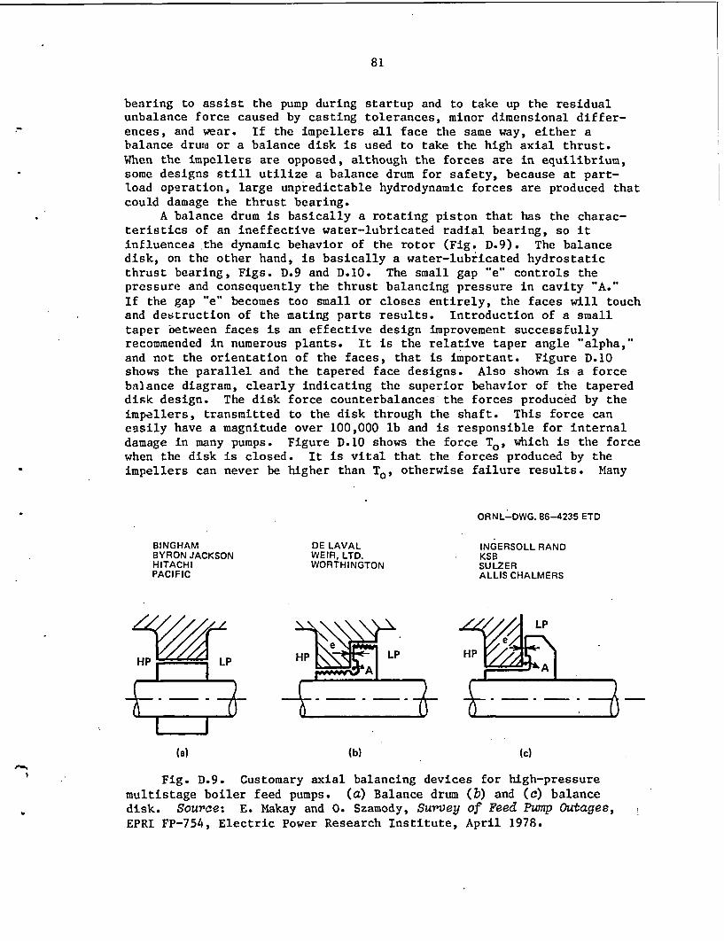
81
bearing to assist the pump during startup and to take up the residualunbalance force caused by casting tolerances, minor dimensional differ-ences, and wear. If the impellers all face the same way, either abalance drums or a balance disk is used to take the high axial thrust.When the impellers are opposed, although the forces are in equilibrium,some designs still utilize a balance drum for safety, because at part-load operation, large unpredictable hydrodynamic forces are produced thatcould damage the thrust bearing.
A balance drum is basically a rotating piston that has the charac-teristics of an ineffective water-lubricated radial bearing, so itinfluences the dynamic behavior of the rotor (Fig. D.9). The balancedisk, on the other hand, is basically a water-lubricated hydrostaticthrust bearing, Figs. D.9 and D.10. The small gap "e" controls thepressure and consequently the thrust balancing pressure in cavity "A."If the gap "e" becomes too small or closes entirely, the faces will touchand destruction of the mating parts results. Introduction of a smalltaper oetween faces is an effective design improvement successfullyrecommended in numerous plants. It is the relative taper angle "alpha,"and not the orientation of the faces, that is important. Figure D.10shows the parallel and the tapered face designs. Also shown is-a forcebalance diagram, clearly indicating the superior behavior of the tapereddisk design. The disk force counterbalances the forces produced by theimpellers, transmitted to the disk through the shaft. This force caneasily have a magnitude over 100,000 lb and is responsible for internaldamage in many pumps. Figure D.10 shows the force To, which is the forcewhen the disk is closed. It is vital that the forces produced by theimpellers can never be higher than To, otherwise failure results. Many
ORNL-DWG. 86-4235 ETD
BINGHAM DE LAVAL INGERSOLL RANDBYRON JACKSON WEIR, LTD. KSBHITACHI WORTHINGTON SULZERPACIFIC ALLIS CHALMERS
~~~~~~~jP~~~~~~~~~~L
HP~~~L
(a) (b) (c)
Fig. D.9. Customary axial balancing devices for high-pressuremultistage boiler feed pumps. (a) Balance drum (b) and (c) balancedisk. Source: E. Makay and 0. Szamody, Survey of Feed Pump Outages,EPRI FP-754, Electric Power Research Institute, April 1978.
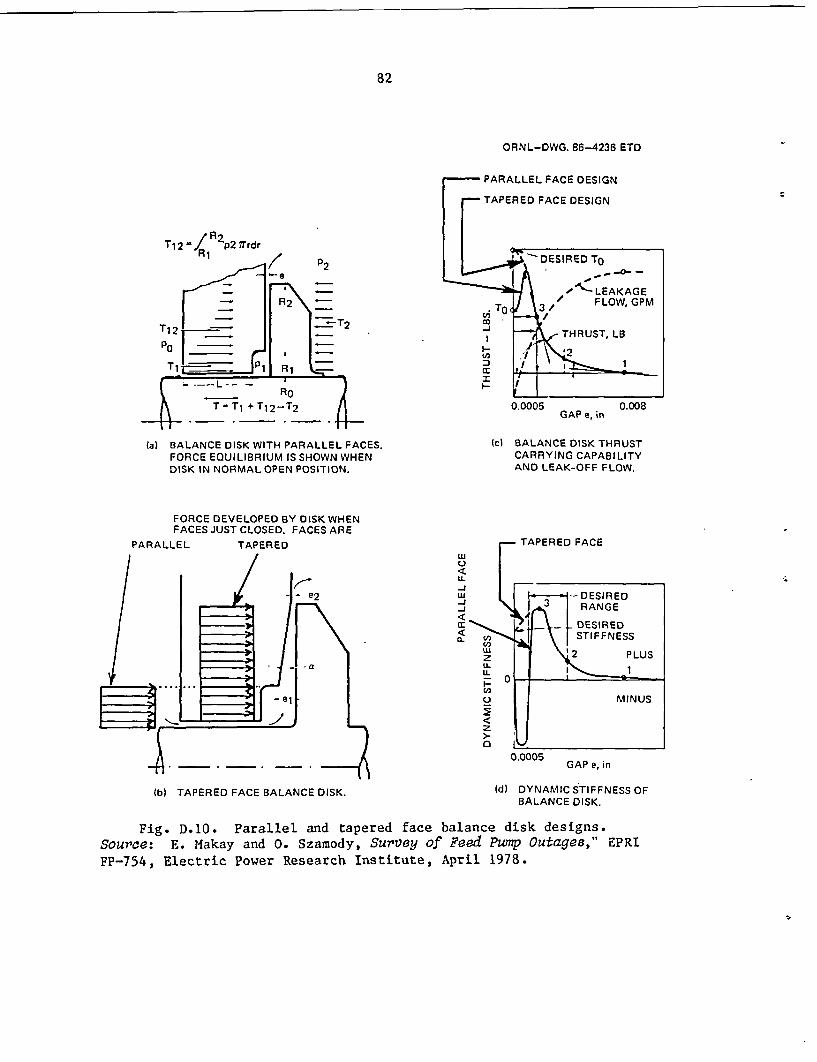
82
ORNL-DWG. 86-4236 ETD
T12 / p2 7TrdrR1
T1 2 -
PO _
T1: jP 1
PARALLEL FACE DESIGN
TAPERED FACE DESIGN
O }\ >~ LEAKGE
J
I
To
I
l V 3 d FLOW. GPM
THRUST. LB
VI
0.0005 0.008GAP e, in
. _
T=j+T 12 -T2
(a) BALANCE DISK WITH PARALLEL FACES.FORCE EQUILIBRIUM IS SHOWN WHENDISK IN NORMAL OPEN POSITION.
FORCE DEVELOPED BY DISK WHENFACES JUST CLOSED. FACES ARE
PARALLEL TAPERED
(c) BALANCE DISK THRUSTCARRYING CAPABILITYAND LEAK-OFF FLOW.
0.0005GAP e, in
(b) TAPERED FACE BALANCE DISK. (d) DYNAMIC STIFFNESS OFBALANCE DISK.
Fig. D.10. Parallel and tapered face balance disk designs.Source: E. Makay and 0. Szamody, Survey of Feed Pump Outages," EPRIFP-754, Electric Power Research Institute, April 1978.

83
failures are due to the fact that the disk design load capacity is mar-ginal when the pump is new. As the wear-ring surfaces wear with normaluse, the hydraulic forces on the impellers grow, resulting eventually ina higher force than the marginal thrust-carrying capability of the disk.Figure D.10 shows the basic principal difference between parallel andtapered face designs, the tapered design having only advantages over theparallel. Note that when the balancing disk is approaching closed posi-tion, the tapered face-design is able to take much higher thrust loadsthan the parallel face design, hence it is much more reliable, particu-larly under large transient loads that accompany severe hydraulic insta-bility.
Complete disintegration of the rotating balance disk reported fromone large generating station called attention to a typical failure mode.Customary material for that component is type 416 SS, where the materialspecification clearly states not to.heat-treat above 42 Rockwell C hard-ness, because the possibility of surface cracking is high. When thefailed component was tested for hardness, it was found to be over 50Rockwell C. Other unused disks were tested and found to be over 42Rockwell C hardness. Surface cracks were found severe enough to ensurefuture failures. This discrepancy was found in at least three manufac-turers' products; thus, it was not a localized problem. It is a goodpractice to test for hardness every time a new disk is put in-service tointercept this type of failure cause. The best practice, however, is toheat-treat the stationary part to somewhat higher hardness, because thatpart is not subjected to centrifugal forces as is the rotating disk.
D.6.2 Shaft seals
Shaft seals have the highest failure-rate for any component inboiler feed pumps. Figure D.11 shows the three seal designs used forboiler and nuclear feedwater pump services with single injection. Doubleinjection is used for high-temperature applications to avoid flashing inthe seal area. Injection water can be regulated by temperature or pres-sure control. Low-speed booster pumps may employ packing; however, high-speed applications (3600 rpm or above) are exempt from that seal applica-tion with the exception of AUXFPs. The majority of failures occur withseal designs other than labyrinth types. Labyrinth seals are the leastdemanding "work horses" of utility pumps.
Floating-ring type or mechanical seals have the highest failure rateamong all pump component failures. When in good condition, the mechanicalseals have lower leakage rate than the labyrinth or packing types butobviously are more prone to wear and failure. eAte: some wear, the sealleakage increases rapidly, especially with the floating-Tgt ype. Thisthen requires excessive maintenance that results in lower pump, henceunit, availability or if not repaired, rapidly decreasing pump deliveredcapacity. Considering the high cost of unit down time to replace failedseals and the high repair cost with the mechanical or floating-ring sealtypes, it becomes obvious that the best seal type for large feed pumps isthe labyrinth type. Several utilities report successful conversions tolabyrinth seals after a long history of failures with the other sealtypes.
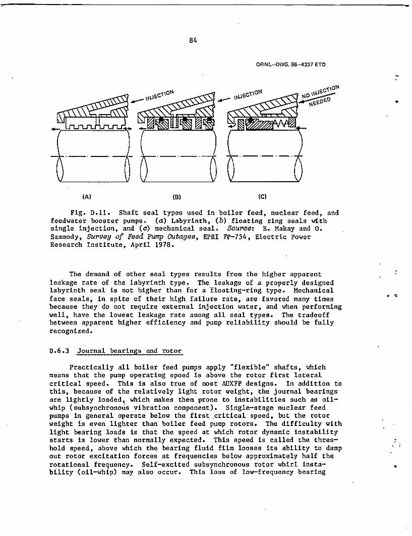
84
ORNL-DWG. 86-4237 ETD
(A) (B) (C)
Fig. D.11. Shaft seal types used in boiler feed, nuclear feed, andfeedwater booster pumps. (a) Labyrinth, (b) floating ring seals withsingle injection, and (c) mechanical seal. Source: E. Makay and 0.Szamody, Survey of Feed Pump Outages, EPRI FP-754, Electric PowerResearch Institute, April 1978.
The demand of other seal types results from the higher apparentleakage rate of the labyrinth type. The leakage of a properly designedlabyrinth seal is not higher than for a 'floating-ring type. Mechanicalface seals, in spite of their high failure rate, are favored many timesbecause they do not require external injection water, and when performingwell, have the lowest leakage rate among all seal types. The tradeoffbetween apparent higher efficiency and pump reliability should be fullyrecognized.
D.6.3 Journal bearings and rotor
Practically all boiler feed pumps apply "flexible" shafts, whichmeans that the pump operating speed is above the rotor first lateralcritical speed. This is also true of most AUXFP designs. In addition tothis, because of the relatively light rotor weight, the journal bearingsare lightly loaded, which makes them prone to instabilities such as oil-whip (subsynchronous vibration component). Single-stage nuclear feedpumps in general operate below the first critical speed, but the rotorweight is even lighter than boiler feed pump rotors. The difficulty withlight bearing loads is that the speed at which rotor dynamic instabilitystarts is lower than normally expected. This speed is called the thres-hold speed, above which the bearing fluid film looses its ability to dampout rotor excitation forces at frequencies below approximately half therotational frequency. Self-excited subsynchronous rotor whirl insta-bility (oil-whip) may also occur. This loss of low-frequency bearing
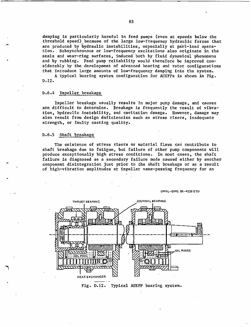
85
damping is particularly harmful in feed pumps (even at speeds below thethreshold speed) because of the large low-frequency hydraulic forces thatare produced by hydraulic instabilities, especially at part-load opera-tion. Subsynchronous or low-frequency excitations also originate in theseals and wear-ring surfaces, induced both by fluid dynamical phenomenaand by rubbing. Feed pump reliability would therefore be improved con-siderably by the development of advanced bearing and rotor configurationsthat introduce large amounts of low-frequency damping into the system.
A typical bearing system configuration for AUXFPs is shown in Fig.D.12.
D.6.4 Impeller breakage
Impeller breakage usually results in major pump damage, and causesare difficult to determine. Breakage is frequently the result of vibra-tion, hydraulic instability, and cavitation damage. However, damage mayalso result from design deficiencies such as stress risers, inadequatestrength, or faulty casting quality.
D.6.5 Shaft breakage
The existence of stress risers or material flaws can contribute toshaft breakage due to fatigue, but failure of other pump components willproduce exceptionally high stress conditions. In most cases, the shaftfailure is diagnosed as a secondary failure mode caused either by anothercomponent disintegration just prior to the shaft breakage or as a resultof high-vibration amplitudes at impeller vane-passing frequency for an
ORNL-DWG. 86-4238 ETD
HEAT EXCHANGER
Fig. D.12. Typical AUXFP bearing system.
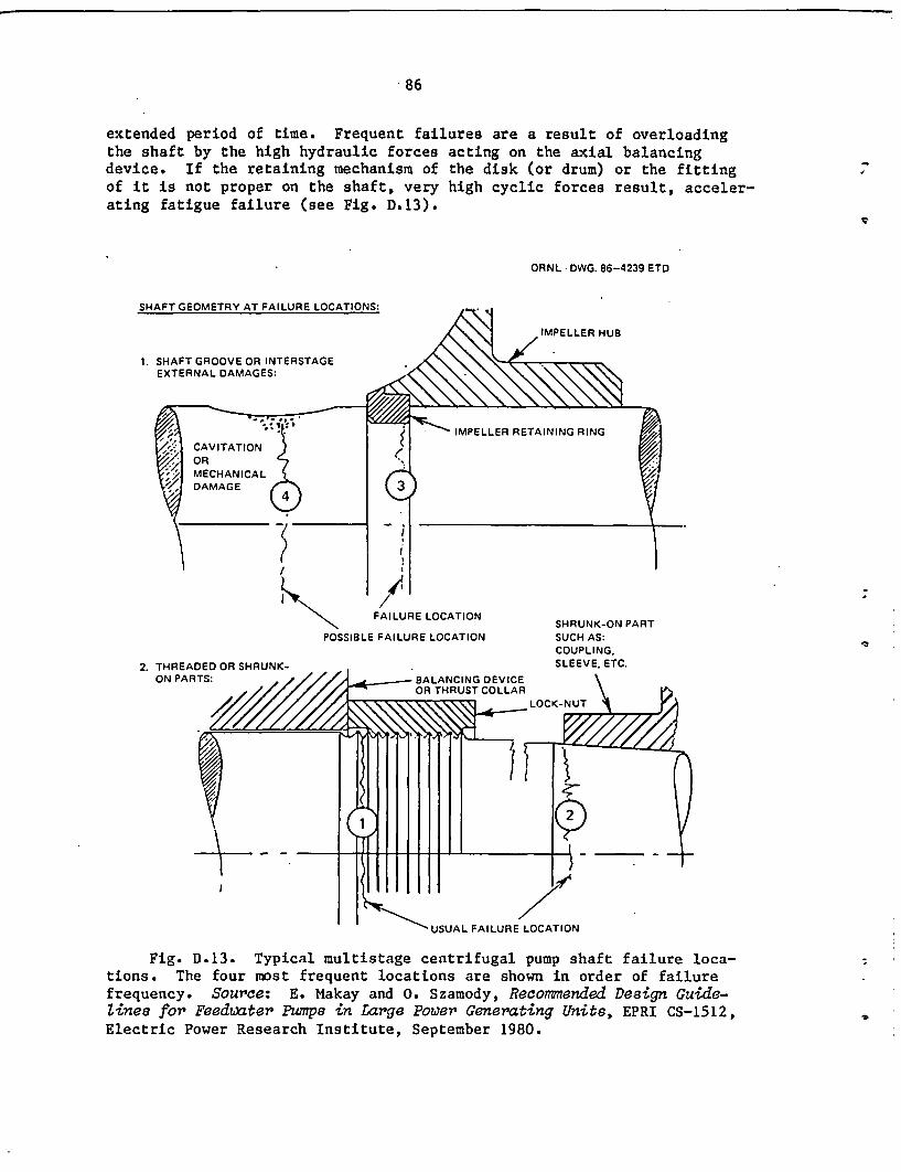
86
extended period of time. Frequent failures are a result of overloadingthe shaft by the high hydraulic forces acting on the axial balancingdevice. If the retaining mechanism of the disk (or drum) or the fittingof it is not proper on the shaft, very high cyclic forces result, acceler-ating fatigue failure (see Fig. D.13).
ORNL DWG. 86-4239 ETD
SHAFT GEOMETRY AT FAILURE LOCATIONS:
IMPELLER HUB
1. SHAFT GROOVE OR INTERSTAGEEXTERNAL DAMAGES:
IMPELLER RETAINING RING
-/ - i
/ 4i
FAILURE LOCATION
POSSIBLE FAILURE LOCATIONSHRUNK-ON PARTSUCH AS:COUPLING.SLEEVE. ETC.2. THREADED OR SHRUNK-
ON PARTS: - y
Fig. D.13. Typical multistage centrifugal pump shaft failure loca-tions. The four most frequent locations are shown in order of failurefrequency. Source: E. Makay and 0. Szamody, Recommended Design Guide-Lines for Feedwater Pumps in Large Power Generating Units, EPRI CS-1512,Electric Power Research Institute, September 1980.

87
D.6.6 Wear rings
Excessive wear of the impeller wear rings is in most cases theresult of excessive shaft flexibility and operation at conditions wherelarge shaft vibrations are encountered; it can also follow journal bear-ing wear. Overly close wear-ring clearances in a new pump or new com-ponents will also lead to rapid wear of the rings. In any case, wear ofthese rings will make it impossible for pump efficiency to be maintainedat the initial level. Therefore, new pumps should have sufficientlylarge clearances to ensure against rubbing or seizure. As with balancingdisks, a proper choice of component materials is important for providinggood accommodation of occasional rubs, thus avoiding consequential pumpfailures and premature replacement of wear rings.
Reference
1. Electric Power Research Institute, "Feed Pump Hydraulic Performanceand Design Improvements," Research Project RP1884-10 (ongoing).
89
NUREG/CR-4597Volume 1ORNL-6282/V1Dist. Category RV
Internal Distribution
1. R. J. Borkowski 18-21. G. A. Murphy2. W. G. Craddick 22. H. E. Trammell
3-6. D. M. Eissenberg 23. ORNL Patent Office7. J. A. Getsi 24. Central Research Library
8-14. W. L. Greenstreet 25. Document Reference Section15. H. D. Haynes 26-27. Laboratory Records Department16. R. C. Kryter 28. Laboratory Records (RC)17. A. P. Malinauskas
External Distribution
29-32. M. L. Adams, Case Western Reserve University, Room 417, GlennanBuilding, Cleveland, OH 44106
33. K. I. Baron, American Society of Mechanical Engineers, UnitedEngineering Center, 345 East 47th Street, New York, NY 10017
34. J. H. Ferguson, Connecticut Yankee Atomic Power Company, R. R.No. 1, Box 127E, East Hampton, CT 06424
35. A. B. Johnson, Pacific Northwest Laboratory, P.O. Box 999,Richland, WA 99352
36-39. E. Makay, Energy Research and Consultants, 900 Overton Avenue,Morrisville, PA 19067
40. C. Michelson, ACRS, 20 Argonne Plaza, Suite 365, Oak Ridge, TN37830
41. S. E. Pace, Electric Power Research Institute, P.O. Box 10412,Palo Alto, CA 94303
42. J. E. Richardson, Division of Engineering Technology, Office ofNuclear Regulatory Research, U.S. Nuclear Regulatory Commission,5650 Nicholson Lane, Rockville, MD 20852
43. R. L. Simard, Institute for Nuclear Power Operations, 1100Circle 75 Parkway, Atlanta, GA 30339
44. M. L. Stanley, EG&G Idaho, Inc., P.O. Box 1625, Idaho Falls, ID83401
45. D. F. Sullivan, Division of Engineering Technology, Office ofNuclear Regulatory Research, U.S. Nuclear Regulatory Commission,5650 Nicholson Lane, Rockville, MD 20852
46. J. H. Taylor, Engineering and Risk Assessment Division, Depart-ment of Nuclear Energy, Brookhaven National Laboratory, Upton,NY 11973
47. J. P. Vora, Division of Engineering Technology, Office ofNuclear Regulatory Research, U.S. Nuclear Regulatory Commission,5650 Nicholson Lane, Rockville, MD 20852
48. Office of Assistant Manager for Energy Research and Development,Department of Energy, Oak Ridge Operations Office, Oak Ridge, TN37831
49-50. Technical Information Center, Department of Energy, Oak Ridge,TN 37831
51-425. Given distribution as shown in NRC category RV (10 - NTIS)

NRC FORM 33S US.NUCLEAR RIGULATORYCOMMISSION I REPORTNUMBERIAsUd'b ,TIOC. ddVol No. -lYi12-841NRCM 1102. DT HE3201. 3202 BIBLIOGRAPHIC DATA SHEET NUREG/CR-4597,
SEE INSTRUCTIONS ON THE REVERSE Vol. 1, ORNL-6282/Vl2 TITLE AND SUBTITLE 3 LEAVE BLANK
Aging and Service Wear of Auxiliary Feedwater Pumpsfor PWR Nuclear Power Plants Volume 1. Operating
Experience and Failure Identification 1 DATE REPORT COMPLETED
MONTH YEAR
5 AUTHORISI June 1986M. L. Adams and E. Makay 6 DATE REPORT ISSUED
Energy Research and Consultants Corporation MONTH YEAR
July 19867 PERFORMING ORGANIZATION NAME AND MAILING ADDRESS tOdeNro. Z Cod) B8 PROJECTtTASK.YWORK UNIT NUMBER
Oak Ridge National LaboratoryP. 0. Box Y 9 FIN OR GRANT NUMB ER
Oak Ridge, TN 37831B0828
10 SPONSORING ORGANIZATION NAME AND MAILING ADDRESS .c1.,d#ZDpCode) Ila TYPE OF REPORT
Division of Engineering Technology TOffice of Nuclear Regulatory Research TopicalU.S. Nuclear Regulatory Commission I. PERIOD COVERED f.lcfs..atesi
Washington, DC 20555
12 SUPPLEMENTARY NOTES
'3 ABSTRACT 1200 .ooiC oc Pi,#
Typical auxiliary feedwater pump (AUXFP) configurations are described in terms ofconfiguration details, materials of construction, operating requirements, and modesof operation. AUXFP failure modes and causes due to aging and service wear areidentified and explained, and measurable parameters (including functional indicators)for potential use in assessing operational readiness, establishing degradation trends,and detecting incipient failures are given.
A series of measures to correct present deficiencies in surveillance, monitoring,and in-service testing practices is discussed. The main body of the report issupplemented by a number of relevant appendixes; in particular, a major appendixis included on engineering and design information useful to assess AUXFP operationalreadiness. t
This report was produced under the U.S. Nuclear Regulatory Commission's Nuclear PlantAging Research Program.
IS AVAILABILITY14 DOCUMENT ANALYSIS - a KEVWORDS.OESCRIPTORS
Pumps, centrifugal pumps, auxiliary feedwater pumps, aging, service wear,maintenance, degradation, trend, failure mode, failure cause, measurableparameter, incipient failure, inspection, surveillance, monitoring,functional indicators, operating experience
a IDENTIFIERS CPEN ENDED TERMS
STATEMENT
Unlimited
16 SECURITYCLASSIFICATION
ITA's ofiel
Unclassified
Unclassified' 'NUMBtR OF PAGES
Id PRICE