numerical study of the shock wave and pressure induced by
TRANSCRIPT

Phys. Fluids 33, 073311 (2021); https://doi.org/10.1063/5.0055727 33, 073311
© 2021 Author(s).
Numerical study of the shock wave andpressure induced by single bubble collapsenear planar solid wallCite as: Phys. Fluids 33, 073311 (2021); https://doi.org/10.1063/5.0055727Submitted: 02 May 2021 . Accepted: 19 June 2021 . Published Online: 16 July 2021
Xiaobin Yang (杨晓彬 ), Cheng Liu (刘成 ), Decheng Wan (万德成 ), and Changhong Hu (胡长洪 )
ARTICLES YOU MAY BE INTERESTED IN
A modified Oldroyd-B model for non-colloidal suspensionsPhysics of Fluids 33, 073105 (2021); https://doi.org/10.1063/5.0059382
The wobbling motion of single and two inline bubbles rising in quiescent liquidPhysics of Fluids 33, 073305 (2021); https://doi.org/10.1063/5.0055804
Unsteady flow structures behind a shark denticle replica on the wall: Time-resolved particleimage velocimetry measurementsPhysics of Fluids 33, 075109 (2021); https://doi.org/10.1063/5.0057699

Numerical study of the shock wave and pressureinduced by single bubble collapse near planarsolid wall
Cite as: Phys. Fluids 33, 073311 (2021); doi: 10.1063/5.0055727Submitted: 2 May 2021 . Accepted: 19 June 2021 .Published Online: 16 July 2021
Xiaobin Yang (杨晓彬),1 Cheng Liu (刘成),1,a) DechengWan (万德成),1 and Changhong Hu (胡长洪)2
AFFILIATIONS1Computational Marine Hydrodynamic Lab (CMHL), School of Naval Architecture, Ocean and Civil Engineering,Shanghai Jiao Tong University, Shanghai 200240, China2Research Institute for Applied Mechanics, Kyushu University, Fukuoka 816-0811, Japan
a)Author to whom correspondence should be addressed: [email protected]
ABSTRACT
Bubble collapse is one of the leading causes for the cavitation erosion of submerged structures. For better understanding of the destructivemechanism of cavitation, high-fidelity simulation is performed to simulate the complete process of single bubble collapse near a planar solidwall. The wave propagation method with the approximate Riemann solver Harten Lax and van Leer Contact is adopted to solve the com-pressible two-phase five-equation model. We implement fifth-order weighted essentially non-oscillatory scheme with the block-structuredadaptive mesh method to resolve shock waves and moving interface with high-resolution. We simulate single bubble collapsing in free-fieldto validate the present numerical methods and solver. Our results (e.g., averaged bubble-interior pressure and the radius variation) are foundin excellent agreement with the theoretical Keller–Miksis solutions. In this study, the shock wave transmitted inside the bubble and thewater-hammer shock formed in the liquid are under quantitative investigation. Numerical results reveal that the interactions between theshock wave and bubble interface give rise to peak pressures of liquid phase, and the initial stand-off distances have important influence onshock wave pattern, wall peak pressure, and bubble dynamics.
Published under an exclusive license by AIP Publishing. https://doi.org/10.1063/5.0055727
I. INTRODUCTION
Bubble collapse in near-wall region is commonly encounteredin many industrial processes, such as ultrasonic cavitation, propellercavitation, and underwater explosion, etc. Shock waves1,2 and there-entrant jets generated3–6 from bubble collapse may cause severestructural damage. To fully understand the mechanism of bubble col-lapse, various experimental methods have been developed. The spark-generated5,7–12 bubble and laser-induced13–18 bubble techniques arethe classical experimental methods for creating cavitation bubbles, andhigh-speed photography can be used for the visualization of the re-entrant jet and emission of shock.
Simplified theoretical models are also proposed to provide moredetails of density, pressure, etc., of an inertial cavitation bubble. Thefirst theoretical method to predict a spherical bubble collapse in free-field was proposed by Rayleigh,1 based on the spherical symmetryassumption of a bubble. Later, Plesset19 improved Rayleigh’s methodby adding the viscous and surface tension effects, which is now theprominent Rayleigh–Plesset (R–P) equation. After that, numerous
improvements for the R–P equation have been proposed, in particular,Keller and Miksis20 included the compressibility effects of liquid to theR–P equation and derived the well-known Keller–Miksis (K–M) equa-tion. The solutions of the R–P equation and K–M equation have beenwidely used as the validation of CFD (Computational Fluid Dynamics)approaches.21–23 However, when the collapse is initiated in the vicinityof a solid wall, the presence of wall boundary hinders the inward liquidflow around bubble, leading to non-spherical collapse, which cannot beeffectively resolved by the aforementioned theoretical approaches.24
In addition to the theoretical and experimental methods, numeri-cal simulations have also been extensively used to study bubble col-lapse. Plesset and Chapman25 were the first to develop boundaryintegral method (BIM) for the simulation of near-wall bubble collapse.BIM assumes the fluid to be non-viscous and incompressible, whichhighly improves efficiency and saves computational costs. AlthoughBIM has been widely adopted to study bubble collapse problems,26–32
the propagation of shock wave in fluid phase cannot been captured,and additional models are required whenever compressibility effects
Phys. Fluids 33, 073311 (2021); doi: 10.1063/5.0055727 33, 073311-1
Published under an exclusive license by AIP Publishing
Physics of Fluids ARTICLE scitation.org/journal/phf

are dominating. These limitations make it difficult to capture the mainflow characteristics of violent collapses. Therefore, high-fidelity simu-lation based on the compressible two-phase flow equations becomesmore desirable. It can reproduce an experiment with abundant andquantitatively temporal and spatial information, by which the evolu-tion of shock waves and corresponding affection can be analyzed.
The high-density ratio of two phase fluids and the strong discon-tinuities of the flow field make the problem complicated and bringgreat challenges to the simulation. Liu and Hu33 took advantage ofTHINC (Tangent of Hyperbola for Interface Capturing)34 and GFM(Ghost Fluid Method)35 to simulate the collapse of an air bubble undershock in water accurately. Allaire et al.36 proposed a robustmechanical-equilibrium five-equation model for the simulation of theinterfaces between compressible two-phase flows with high-densityratio, and the shock-induced collapse was simulated. Based on Allaireet al.’s work,36 Deng et al.37 presented a novel low-dissipative BVD(boundary variation diminishing) scheme and simulated the three-dimensional shock–bubble interactions. The BVD scheme employsmore than one reconstruction function to minimize the variations(jumps) of the reconstructed variables at cell boundaries, which canresolve discontinuities with much less numerical dissipation. Kapilaet al.38 simplified the seven-equation of Baer and Nunziato39 to a ther-modynamically consistent model, which is similar to the five-equationmodel of Allaire et al.,36 and the only difference between them is thatthe volume fraction equation of Kapila et al.38 includes a source termðKr � uÞ. Schmidmayer et al.23 compared the above two five-equationmodels and the six-equation model of Saurel et al.40 in the simulationof the Rayleigh collapse, and found that the results from the model ofKapila et al.38 and Saurel et al.40 have good agreements with the K–Msolutions, while the model of Allaire et al.36 cannot predict the collapsetime and minimum volume of the Rayleigh collapse accurately.Tiwari21 reduced the Baer–Nunziato model39 to a five-equation modelwith interface regularization terms, and the 3D bubble collapse nearsolid wall was tested. The interface regularization terms can keep thethermodynamically consistent and reduce the numerical diffusion atthe phase interface.
In a bubble collapsing event, the high-speed re-entrant jet andshock wave are generated when the bubble is compressed; ultimately,the collapsing process is usually accomplished with extremely shortperiod of time. Therefore, very fine spatiotemporal resolution isrequired to capture shock wave and flow structure accurately. Beig andJohnsen22 gave a comprehensive study of the temperatures producedduring a 3D bubble collapse near solid wall using more than 900� 106 grids. The large amount of grid makes it not very efficient forthe direct simulations. In order to save the computing expense,numerous simplified methods have been proposed. Shaw and Spelt41
employed the spherically symmetric compressible quasi-conservativeEuler equations with GFM to investigate the shock wave emitted dur-ing bubble collapse in free-field, and 10 000 uniform grids wereadopted in an 1D computational domain. Johnsen and Colonius42–44
studied the shock–bubble interactions in cylindrical coordinates withazimuthal symmetry based on c-based approach proposed by Shyue,45
and 720 000 grids were employed in a 2D computational domain.Hsiao et al.46 linked the BIM solver and the compressible solver tostudy cavitation erosion based on a stretched grid, with finest resolu-tion of 10 lm in a 1� 1m domain. To balance the efficiency andaccuracy, Tian et al.47 employed the adaptive mesh refinement (AMR)
technique and Eulerian finite element method to investigate the effectsof buoyance parameters on the bubble oscillating behaviors.Trummler et al.48 investigated the influence of the grid resolution onthe collapse dynamics and the maximum pressures distribution, andfound that the grid resolution is significant for pressure peaks.
It is well known that the water-hammer shocks and re-entrantjets account for most of cavitation erosion of the structures. In theexperiment of laser-induced bubble collapsing, the emissions of shockwave during bubble rebounding can be detected with a needle-typehydrophone (Johansen et al.49). Numerical simulation provides analternative way to study the shock wave emissions in the expansionstage of bubble explosion (Lechner et al.24), based on a multiphaseflow solver InterFoam, and also by Tian et al.50 using Eulerian finite-element method. Cao et al.51 studied shock-induced near-wall bubblecollapse numerically and captured the emitted shock waves in the liq-uid during collapse with phenomenological model. Johnsen andColonius44 found that the precursor shock preceded the water-hammer shock in free-field shock-induced collapse; however, the pre-cursor shock is not clearly resolved due to the numerical dissipation.Lechner et al.52 found when a bubble collapses very close to a solidboundary, and the jet speed can reach up to�1000m/s.
Although shock wave emissions are extensively exist in bubblecollapse, few of the numerical works emphasize the formation andpropagation of the shock wave system around the interface, especiallyfor the shocks generated inside the bubble before the emission ofwater-hammer shocks. Moreover, due to the numerical diffusion, theshock waves might not be resolved sharply for long-timescale simula-tion if traditional upwind schemes are applied. To overcome these dif-ficulties, a compressible two-phase flow solver based on the fifth-orderWENO (weighted essentially non-oscillatory) scheme53 is developed.One significant advance in the present simulation is the use of block-structured AMR method.33 AMR allows one to capture the shockwaves and other discontinuities with high resolution, and keep thecompact thickness of the interface, while leaves other non-criticalregions covered with coarse mesh, providing savings in both the com-putational time and data storage. With the above approaches, the vio-lent oscillations of the bubble interface are captured with highresolution, the shock waves formed inside the bubble are well-resolved, and the propagation and refraction of the shocks can beinvestigated quantitatively; in particular, the interactions of the shockwaves and the bubble interfaces are analyzed in detail. The pressurepeaks on the solid wall caused by the shock waves and the re-entrantjets are also studied.
The highlight of the present study lies in the following fouraspects: (1) High-resolution compressible multiphase solver basedon WENO and adaptive mesh is developed to improve the compu-tational efficiency and accuracy in simulating bubble collapse. (2)Bubble pressure and radius predicted by this solver agree well withthe theoretical solutions, even for large pressure and density ratiocases. (3) Shock waves and pressure peaks inside the bubble or inthe liquid are resolved with high resolution, and the shock wavegeneration mechanism and the interaction between shock waveand bubble interface in the whole process of collapsing are studiedquantitatively. (4) Influences of the initial stand-off distances onthe peak wall pressure are discussed; the primary reason for thecavitation damage is identified to be the shock wave rather thanthe re-entrant jet.
Physics of Fluids ARTICLE scitation.org/journal/phf
Phys. Fluids 33, 073311 (2021); doi: 10.1063/5.0055727 33, 073311-2
Published under an exclusive license by AIP Publishing
The paper is structured as follows. Numerical approaches areintroduced in Sec. II. Numerical validations are presented inSec. III, including the convergence study and the comparisons ofthe present numerical results and the semi-analytical K–M solu-tions20 for the Rayleigh collapse. Shock waves generated in the col-lapse of an air bubble near solid wall are quantitatively investigatedin Sec. IVA–IV C, and the wall pressure caused by shock wave andre-entrant jet are studied in Sec. IVD. Finally, some concludingremarks are drawn in Sec. V.
II. NUMERICAL METHODSA. Governing equations
The governing equations of compressible two-phase flows withKapila’s38 five-equation model are given by
@a1q1ð Þ@t
þr � a1q1uð Þ ¼ 0; (1)
@a2q2ð Þ@t
þr � a2q2uð Þ ¼ 0; (2)
@ quð Þ@t
þr � quuþ pð Þ ¼ 0; (3)
@E@t
þr � E þ pð Þuð Þ ¼ 0; (4)
@a2@t
þ u � ra2 ¼ Kr � u; (5)
where ak and qk, denote volume fraction and density, respectively.k ¼ 1 for liquid and k ¼ 2 for gas. u indicates the velocity, p is themixture pressure, and E is the total energy. To prevent spurious oscil-lations, the K term in Eq. (5) is considered on the interface cells wheretwo fluids co-exist,54 and is given by
K ¼ a1a2 q1c21 � q2c
22
� �a1q2c
22 þ a2q1c
21
; (6)
where c1 and c2 denote the sound speed of each phase. To close thegoverning equations, the stiffened gas equation of state (SG EOS)55 isadopted
p ¼ c� 1ð Þqe� cp1; (7)
where c is the ratio of specific heats, p1 represents the stiffness con-stant, and e indicates the density of internal energy. The mixing rules38
for two-phase flow can be expressed as
a1 þ a2 ¼ 1; (8)
a1q1 þ a2q2 ¼ q; (9)
a1c1 � 1
þ a2c2 � 1
¼ 1c� 1
; (10)
a1p1;1
c1 � 1þ a2p1;2
c2 � 1¼ p1
c� 1: (11)
In the present study, the sound speed of the mixture flow is com-puted by the mixture variables56,57 as
c2 ¼ c pþ p1ð Þq
: (12)
B. Wave propagation method
The wave propagation method37,58 is used to solve the conserva-tion laws of the form in Eq. (13). By splitting the flux difference intoeigenvectors of Jacobian matrix, high-resolution results can beobtained. In the wave propagation method, flux is assumed to be con-tinuous; thus, it is not required to compute the jumps at the interfacein solving the Riemann problem.59 For completeness, a brief descrip-tion of the wave propagation method is presented as follows.Equations (1)–(5) are rewritten as
@q@t
þ A@q@x
¼ 0; (13)
where q is a vector of conservative variables and A is the flux Jacobianmatrix and can be split into subvectors as
A ¼ RKL; (14)
where K is the diagonal matrix composed of the eigenvalues of A, Rand L are, respectively, the right and left eigenvector matrix corre-sponding to K. Let Dq ¼ qr � ql , where ql and qr are the left andright reconstructed conservative variables at cell boundaries, which arecalculated by WENO scheme. Dq can be reformulated as
Dq ¼ qr � ql ¼ RLDq ¼ r1; r2;…; rnð Þ
l1l2
..
.
ln
0BBBBB@
1CCCCCADq
¼ r1; r2;…; rnð Þ
l1Dq
l2Dq
..
.
lnDq
0BBBBB@
1CCCCCA ¼
Xnk¼1
bkrk; (15)
where rk and lk are the left and right eigenvectors of A correspondingto its eigenvalues kk and bk ¼ lk � Dq. Analogously
A � Dq ¼ RKLDq ¼Xnk¼1
kkwk; (16)
where wk ¼ bkrk refer to the discontinuities (jumps) and can beexpressed as
w1 ¼ q�l � ql;
w2 ¼ q�r � q�l ;w3 ¼ qr � q�r ;
8><>: (17)
the intermediate conservative variables q�l and q�r can be obtained bythe three-wave approximate HLLC (Harten Lax and van LeerContact) Riemann solver.59
At the ith cell, the wave propagation method constructs theRiemann discontinuities at the cell boundaries and inside the cell;then, Eq. (13) can be rewritten as
@qi@t
¼ L qið Þ ¼ � 1Dx
A � Dqi
¼ � 1Dx
AþDqi�12þ A�Dqiþ1
2þ ADqi
� �; (18)
Physics of Fluids ARTICLE scitation.org/journal/phf
Phys. Fluids 33, 073311 (2021); doi: 10.1063/5.0055727 33, 073311-3
Published under an exclusive license by AIP Publishing

where AþDqi�1=2 denotes the fluctuations propagating into the cell atthe left face xi�1=2, with the initial states of the Riemann problemqi�1=2;l and qi�1=2;r . A
�Dqiþ1=2 denotes the fluctuations propagatinginto the cell at the right face xiþ1=2, with the initial states of theRiemann problem qiþ1=2;l and qiþ1=2;r . ADqi is the total fluctuationsinside the cell with qi�1=2;r and qiþ1=2;l as initial states of the Riemannproblem.37,58
The conservative variables qi61=2;r and qi61=2;l at the cell bound-aries are reconstructed by WENO scheme.53 As the WENO schemeitself is not positivity-preserving, to remedy this problem, thepositivity-preserving limiter60 is used.
Finally, third-order Runge–Kutta scheme is adopted to updatethe solution
q 1ð Þ ¼ qn þ DtL qnð Þ;
q 2ð Þ ¼ 34qn þ 1
4q 1ð Þ þ 1
4DtL q 1ð Þ� �
;
qnþ1 ¼ 13qn þ 2
3q 2ð Þ þ 2
3DtL q 2ð Þ� �
;
8>>>>><>>>>>:
(19)
where the superscript n denotes the nth time step, qð1Þ and qð2Þ are theintermediate time values.
For 1D computational domain, the nonreflecting boundary con-ditions applied in the present work are dq=dxjC ¼ 0, where C standsfor the boundary. The reflective boundary conditions are the same asthe nonreflecting boundary conditions except for velocity componentperpendicular C. For instance, the reflecting boundary condition ofvelocity component in x� direction is given as ujC ¼ 0.
C. Adaptive mesh refinement
To improve the computational efficiency, the block-structuredAMR method proposed by Berger and Oliger61 is adopted. Thisapproach makes use of non-overlapped blocks to cover the computa-tional domain, and all blocks are indexed by tree data structure (quad-tree for 2D or oct-tree for 3D). Each block is discretized with identicaltopology and filled by uniformmesh with buffer layers. As a result, theblock-structured AMRmethod is suitable for implementation of high-resolution schemes with wide stencils.
To gain more insight into the block-structured adaptive mesh,the logical relationships of block, guard cell, and computational cellare depicted in Fig. 1. It is shown that the computational domain isdiscretized by a series of blocks, and the refinement is performed nearthe bubble interface [Fig. 1(a)]. Block with buffer layer [Fig. 1(b)] isthe basic unit for computation and performing the loading balancealgorithm.62,63 Each block is divided by N3 uniform mesh (N is thecell number in one axial direction) and a collocated configuration ofphysical variables is used as shown in Fig. 1(c).
For the present fifth WENO scheme, four layers of guard cellsare introduced as buffer layer for the flux computation at block bound-ary. On the other hand, the guard cells in the buffer layer can also beused to construct boundary conditions. Therefore, the guard cellsshould be updated at the end of each time step or after parallel datatransmission. When two adjacent blocks are refined by differentrefinement levels, the fluxes on the block boundaries may not consis-tent. Additional operations should be performed to ensure the fluxconservation. For the guard cells adjacent to refined neighbor blocks,arithmetic average can be used for computing the fluxes. While for the
guard cells adjacent to coarse neighbors, a conservative interpolationapproach33 should be employed.
Refinement criterion used to mark the region to be refined/coarsened is crucial for AMR method. In the present work, a scalarfunction d is defined as
d ¼
ffiffiffiffiffiffiffiffiffiffiffiffiffiffiffiffiffiffiffiffiffiffiffiffiffiffiffiffiffiffiffiffiffiffiffiffiffiffiffiffiffiffiffiffiffiffiffiffiffiffiffiffiffiffiffiffiffiffiffiffiffiffiffiffiffiffiffiffiffiffiffiffiffiffiffiffiffiffiffiffiffiffiffiffiffiffiffiffiffiffiffiffiffiffiffiffiffiffiffiffiffiffiffiffiffi;iþ1 � ;i�1
2Dx
� �2
þ ;jþ1 � ;j�1
2Dy
!2
þ ;kþ1 � ;k�1
2Dz
� �2vuut ;
where ; can be an arbitrary physical field (density, pressure, etc.) ofour interest. Two threshold values dmin and dmax are set to determinewhich block to be refined or coarsened. To reach the desired accuracy,a preliminary numerical assessment for dmin, dmax is necessary. Weuse the following criterions for refine or coarsen of a block: (1). Whend � dmax is detected in one cells of the block, then refine the mesh;(2). when d � dmin is satisfied for any cells of the child blocks, thencoarsen to reduce the mesh resolution. In practical, we need to per-form preliminary numerical tests to determine dmin, dmax until thedesired regions are covered with finest mesh. The grid convergenceand the comparison with theoretical or experimental results are alsohelpful to assess the refinement level. In the present work, the phaseinterface regions should be refined, thus ; ¼ a with dmin ¼ 0:1 anddmax ¼ 0:2 is suggested. The strong discontinuities like shock wavesand contact waves are expected to be captured; therefore, ; ¼ q withdmin ¼ 2000 and dmax ¼ 4000 is applied.
III. NUMERICAL VALIDATION FOR 3D BUBBLECOLLAPSE IN OPEN DOMAIN
In this section, the physical process of single bubble collapse inopen space is simulated by present AMR solver. The numerical resultsare compared with theoretical predictions of K–M model. To assessthe boundary effects, three sets of the domain size are considered.Mesh independency study are also conducted to test the spatial con-vergence property of this scheme.
A. Numerical tests for the adaptive refinementmethod and its efficacy
First, the collapse of a single bubble in infinite liquid is consideredto test the robustness and efficiency of the AMR solver. The numericaltest case shows that the amount of grids in the computational domainwill greatly decrease as the bubble compressed. The long period oftime simulation, including the re-expansion and re-collapse stage ofthe collapse process, proves that the present solver is of highrobustness.
The computational domain is x; y; z 2 ½0; L with L¼ 20R0,where R0 is the initial bubble radius. Initially, the bubble is placed atthe center of the domain with R0 ¼ 0:038. The pressure ratio ispinf =p0 ¼ 100, and the initial density ratio qinf =q0 ¼ 1000, where thesubscript inf denotes the initial pressure in ambient liquid and thesubscript 0 denotes the initial pressure inside the bubble. The nonre-flecting boundary conditions are applied on all boundaries. The refine-ment levels 2–9 are adopted, with minimal grid intervalDxmin ¼ R0=102:4. The coarsest refinement level 2 corresponds to theentire domain discretized by 16� 16� 16, and the finest refinementlevel 10 corresponds to 4096� 4096� 4096 uniform meshes. Thedetailed numerical setup could be found in Table I.
Physics of Fluids ARTICLE scitation.org/journal/phf
Phys. Fluids 33, 073311 (2021); doi: 10.1063/5.0055727 33, 073311-4
Published under an exclusive license by AIP Publishing

For comparison, the simulation time is scaled by Rayleigh col-lapse time1 Tc
Tc ¼ 0:915R0
ffiffiffiffiffiffiffiffiffiffiffiffiffiffiffiffiffiffiffiffiffiqinf
pinf � p0ð Þ
s:
Figure 2 shows the evolution of the block at different time instants.As the bubble shrinks, the refined blocks decrease significantlyuntil the bubble volume reaches minimum at about 1:05Tc; after-ward, the blocks count increases as the bubble rebounds. The finestmesh blocks always cover the bubble interface; thus, AMR is crucialto reduce the dissipation of WENO scheme and to maintain thesharpness of the interface. The variation of total block number(Ntotal) as a function of time for the entire computational domain isgiven in Fig. 3.
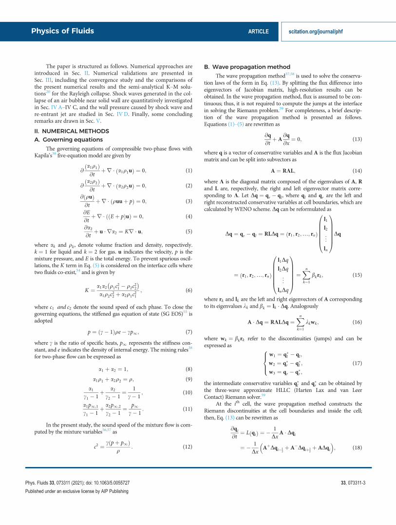
Figure 4 shows the time history of dimensionless averagedbubble-radius R=R0 and non-dimensional averaged bubble pressurep=pinf , where R=R0 is computed by ðV=V0Þ1=3, and V is calculatedfrom
V ¼XX
DxDyDzð Þi � ai;
and p is derived by
p ¼ 1V
XX
DxDyDzð Þi � ai � pi;
where DxDyDzð Þi, ai, and pi denote the volume, gas volume fraction,and pressure of the ith cell, respectively, and X represents the whole
FIG. 1. Refinement principle of the block-structured AMR method. (a) Enlarged view of computational domain discretized by a series of blocks for bubble collapse simulation (red surfacedenotes air bubble), (b) single block that is divided by N3 uniform mesh with buffer layers outside, and (c) single computational cell in the block with physical variables defined in cell center.
TABLE I. Parameters of the collapse of a single bubble in infinite liquid. Note thatuij jmax refers to the maximum velocity in the flow field.
Computational domain sizeLx � Ly � Lz
20R0 � 20R0 � 20R0
Initial bubble radius R0 0.038Initial pressure ratio pinf =p0 100Initial density ratio qinf =q0 1000Time step size Dt CFL� Dxmin=ðjjuijmax þ cjÞCFL (Courant–Friedrichs–Lewy)number
0.3
c1(liquid) 4.4c2(air) 1.4p1;1(liquid) 6� 108
p1;2(air) 0.0
Physics of Fluids ARTICLE scitation.org/journal/phf
Phys. Fluids 33, 073311 (2021); doi: 10.1063/5.0055727 33, 073311-5
Published under an exclusive license by AIP Publishing

computational domain. We can see the time history of bubble radiusand pressure agree well with the K–M solutions, even in the re-collapse and re-expansion stage; thus, it can be concluded that the pre-sent developed AMR solver is capable in simulating the dynamicbehaviors of an oscillating bubble.
B. Computational domain andmeshindependency study
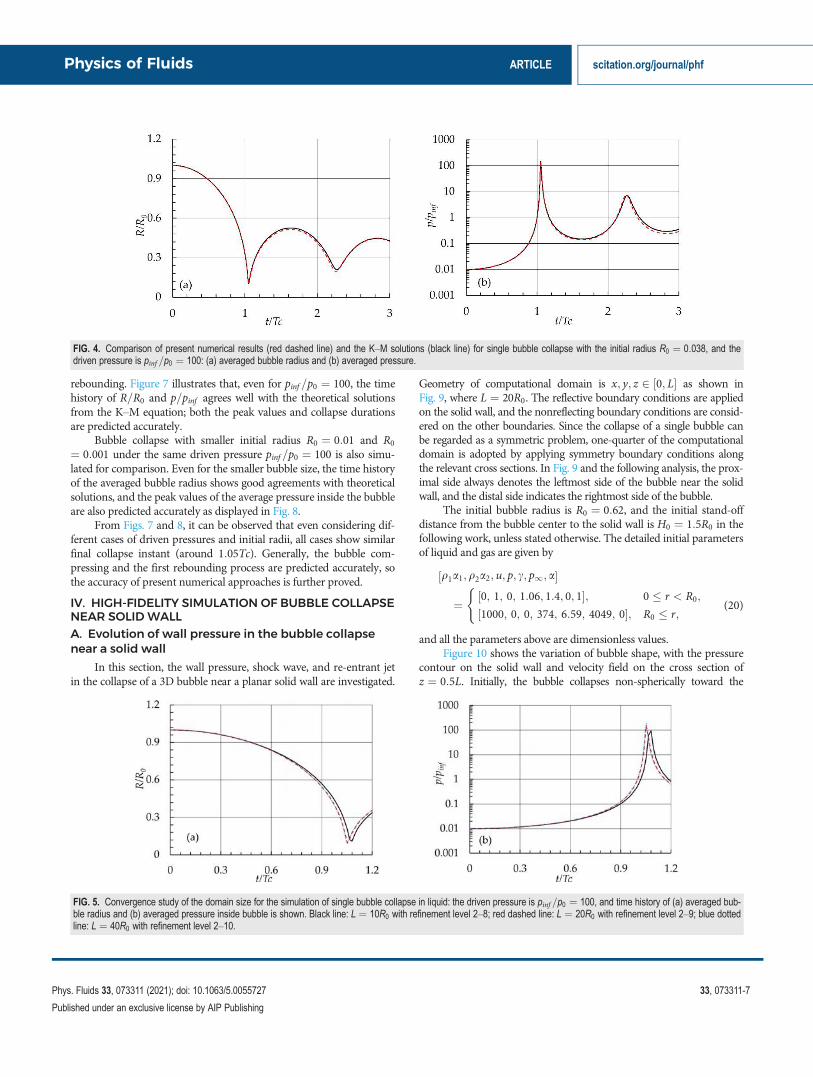
The convergence study of computational domain is conducted toassess the boundary effects. Three cubic computational domains ofx; y; z 2 ½0; L with L¼ 10R0, 20R0, and 40R0 are considered. The
same initial and boundary condition setups are used as in Sec. IIIA. Forthe three domain sizes, the corresponding refinement levels are set as2–8, 2–9, and 2–10 to keep the finest mesh resolutions consistent, thusR0=Dxmin ¼ 102:4 is maintained for all of the three cases. Figure 5 dis-plays the numerical results with different domain size. It is found thattime evolution of bubble radius and pressure converge with the increasein domain size, even with L¼ 10R0, only slight discrepancies near thepeak values are shown. In order to minimize the effects of the far-fieldboundaries, L¼ 20R0 is considered in the following simulations.
Next, the grid convergence study on adaptive mesh is performed.The refinement levels of 2–6, 2–7, 2–8, and 2–9 are tested with thesame size computational domain L¼ 20R0, and the finest refinementlevel 6, 7, 8, and 9 correspond to R0=Dxmin ¼ 12:8, 25:6, 51:2; and102:4, respectively. As shown in Fig. 6, both R=R0 and p=pinf showgood convergence properties; except for the refinement levels of 2–6,slight discrepancies near the peak values are shown. To reduce thecomputing expense and keep high accuracy, the refinement level 2–9is adopted in the following work.
C. Comparison with theoretical predictions
To further validate and assess the reliability of the present AMRsolver, single bubble collapse in open space with different driven pres-sures and initial bubble radii are considered, and the numerical resultsare compared with K–M solutions.20 Figure 7 presents the results ofthe bubble collapse with the initial radius R0 ¼ 0:038 under threedriven pressures, pinf
p0¼ 10; 20; and 100. For higher pressure-ratio
cases, bubble will be compressed into much smaller size with violent
FIG. 2. Block of half computing domain during bubble collapse; each block is discretized by Nx ¼ Ny ¼ Nz ¼ 8, and the red surface denotes iso-surface of a ¼ 0:5.
FIG. 3. Blocks count (Ntotal) during the simulation of single bubble collapse inopen space.
Physics of Fluids ARTICLE scitation.org/journal/phf
Phys. Fluids 33, 073311 (2021); doi: 10.1063/5.0055727 33, 073311-6
Published under an exclusive license by AIP Publishing
rebounding. Figure 7 illustrates that, even for pinf =p0 ¼ 100, the timehistory of R=R0 and p=pinf agrees well with the theoretical solutionsfrom the K–M equation; both the peak values and collapse durationsare predicted accurately.
Bubble collapse with smaller initial radius R0 ¼ 0:01 and R0
¼ 0:001 under the same driven pressure pinf =p0 ¼ 100 is also simu-lated for comparison. Even for the smaller bubble size, the time historyof the averaged bubble radius shows good agreements with theoreticalsolutions, and the peak values of the average pressure inside the bubbleare also predicted accurately as displayed in Fig. 8.
From Figs. 7 and 8, it can be observed that even considering dif-ferent cases of driven pressures and initial radii, all cases show similarfinal collapse instant (around 1:05Tc). Generally, the bubble com-pressing and the first rebounding process are predicted accurately, sothe accuracy of present numerical approaches is further proved.
IV. HIGH-FIDELITY SIMULATION OF BUBBLE COLLAPSENEAR SOLIDWALLA. Evolution of wall pressure in the bubble collapsenear a solid wall
In this section, the wall pressure, shock wave, and re-entrant jetin the collapse of a 3D bubble near a planar solid wall are investigated.
Geometry of computational domain is x; y; z 2 ½0; L as shown inFig. 9, where L ¼ 20R0. The reflective boundary conditions are appliedon the solid wall, and the nonreflecting boundary conditions are consid-ered on the other boundaries. Since the collapse of a single bubble canbe regarded as a symmetric problem, one-quarter of the computationaldomain is adopted by applying symmetry boundary conditions alongthe relevant cross sections. In Fig. 9 and the following analysis, the prox-imal side always denotes the leftmost side of the bubble near the solidwall, and the distal side indicates the rightmost side of the bubble.
The initial bubble radius is R0 ¼ 0:62, and the initial stand-offdistance from the bubble center to the solid wall is H0 ¼ 1:5R0 in thefollowing work, unless stated otherwise. The detailed initial parametersof liquid and gas are given by
q1a1;q2a2; u; p; c; p1; a½
¼ 0; 1; 0; 1:06; 1:4; 0; 1½ ; 0 � r < R0;
1000; 0; 0; 374; 6:59; 4049; 0½ ; R0 � r;
((20)
and all the parameters above are dimensionless values.Figure 10 shows the variation of bubble shape, with the pressure
contour on the solid wall and velocity field on the cross section ofz ¼ 0:5L. Initially, the bubble collapses non-spherically toward the
FIG. 4. Comparison of present numerical results (red dashed line) and the K–M solutions (black line) for single bubble collapse with the initial radius R0 ¼ 0:038, and thedriven pressure is pinf =p0 ¼ 100: (a) averaged bubble radius and (b) averaged pressure.
FIG. 5. Convergence study of the domain size for the simulation of single bubble collapse in liquid: the driven pressure is pinf =p0 ¼ 100, and time history of (a) averaged bub-ble radius and (b) averaged pressure inside bubble is shown. Black line: L ¼ 10R0 with refinement level 2–8; red dashed line: L ¼ 20R0 with refinement level 2–9; blue dottedline: L ¼ 40R0 with refinement level 2–10.
Physics of Fluids ARTICLE scitation.org/journal/phf
Phys. Fluids 33, 073311 (2021); doi: 10.1063/5.0055727 33, 073311-7
Published under an exclusive license by AIP Publishing

planar wall driven by pressure difference. The distal side of the bubblefirst contracts, then involutes, and finally forms a re-entrant jet; thisphysical process is similar to the pioneering work of Plesset andChapman.25 After the re-entrant jet penetrates the proximal side of bub-ble, the bubble splits into several toroidal bubbles by the catapulting jet,and these toroidal bubbles move toward the solid wall with violentdeformations and impinge on the solid wall in the end. According tothe evolution of pressure distribution on the solid wall surface in Fig. 10,the high pressure appears on the center of the wall and gradually reachesmaximum until 1:27Tc; shortly after, the high pressure on the wall sur-face evolves into a circle region and propagates outward radially, whileat the same time, the pressure on the wall center decreases until the re-entrant jet collides with the wall surface. When the pressure on the wallcenter reaches up to the maximum value, the re-entrant jet does notcontact with the wall surface and the velocity contours on the cross sec-tion z ¼ 0:5L also show that the high speed flow not yet contact withthe wall surface. As a result, it can be inferred that the maximum pres-sure on the wall does not result from the jet impacting.
Figure 11 displays the time history of the pressure on the wallcenter and averaged bubble radius. In the initial stage of the collapse,the pressure increases very slowly until 1:22Tc; shortly after, the pres-sure rapidly reaches up to maximum value (note that the bubble radius
achieves its minimum volume at about 1:18Tc). At about 1:27Tc, thepressure on the wall center reaches its first peak value, and later, thepressure decreases rapidly to its minimum at about 1:37Tc; shortlyafter, the pressure increases to the secondary peak; however, the pres-sure magnitude is smaller than the first peak. At this instant (1:37Tc),the tip of the re-entrant jet impacts the solid wall. After that, the pres-sure on the wall center experiences a gradual decrease.
Pressure peaks acting on the wall center play an important role ofcavitation erosion; thus, it is of great importance to identify the reasonsfor the first pressure peak appearing in Fig. 11. To this end, the shockwaves induced initially in the collapse process are studied. Accordingto the evolution of pressure gradients field (Fig. 12), the shock waveemitted by the collapsed bubble propagates toward the wall and finallyresults in high pressure on the wall center. Therefore, the shock waveemission in the collapse process is proven to be the primary reason forthe first peak pressure on the solid wall and the re-entrant jet impact-ing on the solid wall accounts for the second peak pressure. However,there are a few experimental and numerical researches focusing onshock wave emission process of a collapsing bubble, and the mecha-nisms of shock wave formation and evolution are still unclear. In orderto gain more insight into the shock wave emission process, a compre-hensive study of the shock waves upon bubble collapse is performed.
FIG. 6. Mesh independency study for simulating single bubble collapse in liquid: the driven pressure is pinf =p0 ¼ 100, and time history of (a) averaged bubble radius and (b)averaged pressure inside bubble (with an enlarge view in the right) is shown. Black line: L ¼ 20R0 with refinement level 2–6; red dashed line: L ¼ 20R0 with refinement level2–7; blue dotted line: L ¼ 20R0 with refinement level 2–8; green dashed-dotted line: L ¼ 20R0 with refinement level 2–9.
Physics of Fluids ARTICLE scitation.org/journal/phf
Phys. Fluids 33, 073311 (2021); doi: 10.1063/5.0055727 33, 073311-8
Published under an exclusive license by AIP Publishing

B. Formation of shock waves in the collapse process
The formation of a precursor shock ahead of the water-hammershock was observed in the experiment by Ohl et al.64 As stated by Lindauand Lauterborn,65 the water-hammer pressure is partly caused by precur-sor shock, while Johnsen and Colonius44 explained that the piston-like
motion of the re-entrant jet leads to the generation of precursor shock. Toclarify the generation of water-hammer shock, the entire process of near-wall bubble collapse is simulated by the present AMR solver.
Figure 13 presents the pressure gradient ( r pj j) field on the crosssection z ¼ 0:5L. When the distal side of bubble deforms inward the
FIG. 7. Comparison of present numerical results (red dashed line) and the K–M solutions (black line) of the averaged bubble radius (left) and pressure history (right) for singlebubble collapse, with the same initial radius R0 ¼ 0:038 and (a) pinf =p0 ¼ 10, (b) pinf =p0 ¼ 20, and (c) pinf =p0 ¼ 100.
Physics of Fluids ARTICLE scitation.org/journal/phf
Phys. Fluids 33, 073311 (2021); doi: 10.1063/5.0055727 33, 073311-9
Published under an exclusive license by AIP Publishing

FIG. 8. Comparison of the present numerical results (red dashed line) and the K–M solutions (black line) of the averaged bubble radius (left) and pressure history (right) forsingle bubble collapse; the initial radius of (a) R0 ¼ 0:01, (b) R0 ¼ 0:001 with the same driven pressure pinf =p0 ¼ 100 is considered.
FIG. 9. Schematic diagram of computational domain for bubble collapse near solid wall: (a) geometric configuration, the blue surface in the left side of the computationaldomain is the solid wall and the red sphere denotes the air bubble, the symmetry boundary conditions are applied on the yellow cross sections; (b) cross section of z ¼ 0:5L.
Physics of Fluids ARTICLE scitation.org/journal/phf
Phys. Fluids 33, 073311 (2021); doi: 10.1063/5.0055727 33, 073311-10
Published under an exclusive license by AIP Publishing

FIG. 10. Pressure contours on the wall surface, velocity fields on the cross section z ¼ 0:5L, and bubble profiles during bubble collapse at different time instants; the red sur-face denotes iso-surface of a ¼ 0:5.
Physics of Fluids ARTICLE scitation.org/journal/phf
Phys. Fluids 33, 073311 (2021); doi: 10.1063/5.0055727 33, 073311-11
Published under an exclusive license by AIP Publishing

bubble, a shock wave generates inside the bubble; it becomes more vis-ible as the advancing of re-entrant jet. The shock wave propagatestoward the proximal side and is refracted at 1:170Tc. Subsequently, aprecursor transmitted shock is formed in the liquid, together with areflected shock inside the bubble (1:171Tc). With the precursor shockpropagating away from the bubble interface, the reflected shock pene-trates the tip of the re-entrant jet into the liquid at 1:172Tc. Shortlyafter the re-entrant jet impacting on the proximal side of bubble, amore intense water-hammer shock wave is emitted. The water-hammer shock toward the solid wall merges with the precursor shockat 1:176Tc. More shock waves with complex interference are observedon the bubble tip region (1:176Tc); two visible shocks propagatinginside the toroidal bubble at 1:176Tc and 1:184Tc are also captured. Itis noted that the shape of the bubble interface is almost undistortedafter the shock inside the bubble penetrates the bubble tip. As thewater-hammer shock propagates, finally an approximately sphericalshape is developed (1:184Tc).
Numerical simulations show that the piston-like re-entrant jetmay lead to a rapid compression process of the gas and create shock
wave inside the bubble due to the pressure difference. To clarify therelations between the precursor shock and the re-entrant jet, the evolu-tion of pressure field inside the bubble is analyzed.
C. Relations of pressure and shock waves
In this section, the shock generation and emission, shock–interface, shock–shock interactions as well as the relations betweenshocks and pressure field are investigated quantitatively. Figure 14shows the pressure distribution and pressure gradient on the partialcross section z ¼ 0:5L. As time elapsing, the high-pressure region isfound around the distal side of bubble, giving rise to the deformationof bubble interface. As the distal side of bubble developing into a re-entrant jet, the pressure jump inside the bubble becomes visible gradu-ally (Fig. 14). Figure 15 shows the pressure and volume fraction alongthe centerline of the computational domain at different time instants.At 1:141Tc, the pressure discontinuity inside bubble is formed in frontof the re-entrant jet. As the bubble is compressed more, the pressureon the distal side increases rapidly, and a sharp pressure jump isobserved at t ¼ 1:163Tc and t ¼ 1:168Tc. It is shown that the leftpressure peak always appears on the distal side of the bubble as thedeforming of the interface [Figs. 15(c) and 15(d)].
Shock wave generated inside the bubble will impact the bubbleinterface ahead of the re-entrant jet impinging on the proximal side ofthe bubble, and an abrupt increase in pressure (Fig. 16) in the bubble tipregion is observed. Figure 17 depicts the process of shock–interfaceinteraction from the instant when the shock wave inside the bubble pen-etrates the bubble interface. It can be seen that the pressure on the proxi-mal side of bubble increases rapidly forming a pressure peak, whichis much higher than the pressure in the ambient liquid. As shown inFigs. 17(c)–17(f), two pressure discontinuities are generated around theproximal bubble interface, corresponding to the transmitted andreflected shock wave in Fig. 16. After the shock penetrates the bubbleinterface, the pressure peak on the proximal side of bubble almostreaches up to 60pinf (1.1707Tc). The transmitted shock wave propagatesinto the liquid forming a precursor shock, followed by a reflected shockwave propagating inside the bubble as shown in Fig. 16.
Shortly after the shock wave refracting at the proximal side of thebubble, the re-entrant jet contacts with the bubble interface leaving ahigher pressure region as displayed in Fig. 18. Subsequently, thebubble splits into a toroidal-shape bubble, followed by the emission of
FIG. 11. Time history of wall pressure (black line) and averaged bubble radius (reddashed line); two pressure fields corresponding to the instants of the two pressurepeaks are presented.
FIG. 12. Pressure gradients (right) on cross section z¼ 0.5L at different time instants, together with the pressure field on solid wall (left); the red surface denotes iso-surfaceof a ¼ 0:5.
Physics of Fluids ARTICLE scitation.org/journal/phf
Phys. Fluids 33, 073311 (2021); doi: 10.1063/5.0055727 33, 073311-12
Published under an exclusive license by AIP Publishing

FIG. 13. Pressure gradient contours onthe cross section z¼ 0.5L at different timeinstants: x ¼ 0 corresponds to the posi-tion of the solid wall, and the red linedenotes iso-surface of a ¼ 0:5.
FIG. 14. Pressure (top) and pressure gradient $ pj j (bottom) contours on the cross section z¼ 0.5L at different time instants: x denotes the distance from the solid wall andx ¼ 0 is the location of the solid wall, and the red line denotes iso-surface of a ¼ 0:5.
Physics of Fluids ARTICLE scitation.org/journal/phf
Phys. Fluids 33, 073311 (2021); doi: 10.1063/5.0055727 33, 073311-13
Published under an exclusive license by AIP Publishing

water-hammer shock. The water-hammer shock propagates in liquidradially and merges with the precursor shock at about 1:1743Tc. InFig. 19, it can be found that the reflected shock impacts the tip of there-entrant jet and generates a much higher pressure peak (up to135pinf ) in liquid phase. It is noted that the high-pressure region
spreads in the entire domain, including regions away from the wall(Fig. 18). When the re-entrant jet impacts the proximal side of bubble[Fig. 19(e), 1:1722Tc], another peak pressure appears at the contactregion, such that the water-hammer shock is generated (1:1728Tc)accordingly. Figure 19(g) shows that the water-hammer pressure
FIG. 15. Pressure and volume fraction on the centerline from x ¼ 0:4 to x ¼ 1:2, at instants (a) t¼ 1.141Tc, (b) t¼ 1.152Tc, (c) t¼ 1.163Tc, and (d) t¼ 1.168Tc. Black line:Pressure; red dashed line: volume fraction.
FIG. 16. Pressure (top) and pressure gradient (bottom) contours on the cross section z¼ 0.5L at different time instants, x ¼ 0 is the location of the solid wall, the red linedenotes iso-surface of a ¼ 0:5.
Physics of Fluids ARTICLE scitation.org/journal/phf
Phys. Fluids 33, 073311 (2021); doi: 10.1063/5.0055727 33, 073311-14
Published under an exclusive license by AIP Publishing

increases up to maximum at about 1:1733Tc, with the magnitudealmost equal to the peak pressure generated by the collision ofreflected shock and the re-entrant jet [Fig. 19(c)]. In the final stage,water-hammer shock toward the wall merges with the precursor shockat 1:1756Tc. In Figs. 19(g) and 19(h), the water-hammer shock mov-ing away from the solid wall dissipates gradually and makes thereflected shock sharper, but does not merge with the reflected shock.According to Fig. 19, it can be concluded that the impact of the re-entrant jet on the reflected shock occurs before the generation of thewater-hammer shock, which strengthens the reflected shock.
As aforementioned, the precursor shock and water-hammershock are emitted during the collapse, which may have great potentialdamage to the planar wall; thus, the evolutions of the pressure fieldafter shock wave emission are also discussed. Figure 20 presents theinstantaneous pressure curves after the water-hammer shock and pre-cursor shock are merged. At the beginning, pressure waves with twovisible peaks propagate in opposite direction. The left pressure peak isdissipated rapidly while the right pressure shock is strengthened as itpropagating away from the wall. A large pressure peak is generatedwhen the top and bottom water-hammer shocks are focused, with
FIG. 17. Pressure and volume fraction on the centerline from x ¼ 0:55 to x ¼ 0:7, at instants (a) t¼ 1.1691Tc, (b) t¼ 1.1694Tc, (c) t¼ 1.1696Tc, (d) t¼ 1.1698Tc, (e)t¼ 1.1701Tc, and (f) t¼ 1.1707Tc. Black line: Pressure; red dashed line: volume fraction.
Physics of Fluids ARTICLE scitation.org/journal/phf
Phys. Fluids 33, 073311 (2021); doi: 10.1063/5.0055727 33, 073311-15
Published under an exclusive license by AIP Publishing

FIG. 18. Pressure (top) and pressure gradient (bottom) contours on the cross section z¼ 0.5L at different time instants: x denotes the distance from the solid wall and x ¼ 0is the location of the solid wall; the red line denotes iso-surface of a ¼ 0:5.
FIG. 19. Pressure and volume fraction on the centerline from x ¼ 0:55 to x ¼ 0:65, at instants (a) t ¼ 1:1712Tc, (b) t ¼ 1:1715Tc, (c) t ¼ 1:1718Tc, (d) t ¼ 1:1720Tc, (e)t ¼ 1:1722Tc, (f) t ¼ 1:1728Tc, (g) t ¼ 1:1733Tc, (h) t ¼ 1:1743Tc, and (i) t ¼ 1:1756Tc. Black line: Pressure; red dashed line: volume fraction.
Physics of Fluids ARTICLE scitation.org/journal/phf
Phys. Fluids 33, 073311 (2021); doi: 10.1063/5.0055727 33, 073311-16
Published under an exclusive license by AIP Publishing

maximum pressure reaching up to 450pinf ½1:196Tc, Fig. 20(a)].Afterward, the peak pressure declines quickly to about 60pinf ½1:206Tc,Fig. 20(b)], which is still higher than the leftmost pressure peak. As thepressure wave propagating away from the shock impacting site, alow-pressure region is formed. Finally, the left moving pressure shockcollides with the solid wall, leading to high wall pressure up to about21pinf .
From the numerical results in Fig. 20, we can find that the shockaway from the solid wall can give rise to tremendous pressure pulse,even though it has little influence on the planar solid wall. However,this pressure pulse may lead to the structure damage in the oppositedirection. The great dissipations of the shock wave in the liquid arealso observed; thus, the impacting strength of the shock on the solidwall depends strongly on the initial stand-off distance.
D. Influence of initial stand-off distanceon wall pressure
In this subsection, the effect of the initial stand-off distances(from the bubble center to the solid wall) on maximum wall pressureis investigated. Specifically, case studies with initial stand-off distancesH0 ¼ 1:1R0, 1:3R0, 1:5R0, 1:7R0, 2:0R0; and 2:5R0 are performedusing present AMR solver.
By placing a pressure probe on the centroid of the planar wall,time history of the wall pressure for the above-mentioned cases isgiven in Fig. 21. It is found that although the initial stand-off distancesare different, the first pressure peaks induced by the shock impactingare always higher than the second peaks induced by the re-entrant jet,which further confirms that the water-hammer shocks is moredestructive than the re-entrant jet. Also, we note that the initial stand-off distances have significant influence on the peak wall pressure.When H0 < 2:0R0, the pressure peaks change substantially withrespect to the variations of the initial stand-off distance. In particular,for H0 ¼ 1:1R0 case (the gap between the bubble front and wall is0:1R0), the magnitude of the first pressure peak reaches 63pinf , whichis much higher than the subsequent pressure peak (38pinf ) caused byre-entrant jet. For H0 ¼ 1:3R0 case, the first pressure peak reaches35pinf , and the second reduces to 19pinf . When H0 ¼ 1:5R0, the first
pressure peak reaches 21pinf , and the second declines to 12pinf . ForH0 ¼ 2:5R0 case, the shock wave still causes high pressure on the wallwith the first pressure peak up to 8pinf . It is also observed that the firstpressure peak appears approximately at a similar instant forH0 ¼ 1:1R0, 1:3R0 1:5R0, and 1:7R0 cases, while the second pressurepeak occurs at different times. Since the pressure wave toward planarwall dissipates quickly (Fig. 20), the intensity of the wall pressure willbe affected greatly by the initial stand-off distance. We may infer thatthe shock wave propagates with extremely high speed comparable tothe speed of sound in liquid. However, the flow speed of re-entrant jetis much lower. Thus, a visible phase differences are expected for thesecond pressure peaks of various H0. In Fig. 21, the obvious delay ofthe second pressure peaks is found for the six cases; moreover, the val-ues of the second peak pressure decrease significantly with the increasein initial stand-off distance. We notice that when the initial stand-offdistances H0 < 2:0R0, the wall pressure oscillates violently after there-entrant jet impacting, while for H0 ¼ 2:5R0, the pressure curve isrelatively smooth (Fig. 21). To identify the sources of the pressureoscillation, bubble dynamic behaviors during collapse are investigated.
FIG. 20. Evolution of pressure distribution on the centerline from x ¼ 0 to x ¼ 1:2. (a) Black line: t ¼ 1:179Tc, red line: t ¼ 1:184Tc, purple line: t ¼ 1:196Tc, green line:t ¼ 1:197Tc, blue line: t ¼ 1:2Tc, yellow line: t ¼ 1:206Tc; (b) Black line: t ¼ 1:206Tc, red line: t ¼ 1:213Tc, purple line: t ¼ 1:222Tc, green line: t ¼ 1:238Tc, blue line:t ¼ 1:254Tc, yellow line: t ¼ 1:27Tc, dark red line: t ¼ 1:286Tc.
FIG. 21. Time history of the wall pressure at the wall center x; y; z½ ¼0:0; 6:2; 6:2½ for the different initial stand-off distances. Black line: 1:1R0, redline: 1:3R0, purple line: 1:5R0, green line: 1:7R0, blue line: 2:0R0, yellow line:2:5R0.
Physics of Fluids ARTICLE scitation.org/journal/phf
Phys. Fluids 33, 073311 (2021); doi: 10.1063/5.0055727 33, 073311-17
Published under an exclusive license by AIP Publishing

FIG. 22. Evolution of a collapsing bubble with initial stand-off distance of 1:7R0 (rendered by volume fraction).
Physics of Fluids ARTICLE scitation.org/journal/phf
Phys. Fluids 33, 073311 (2021); doi: 10.1063/5.0055727 33, 073311-18
Published under an exclusive license by AIP Publishing

FIG. 23. Evolution of a collapsing bubble in the later stage with initial stand-off distance of 2:0R0 in the left row, 2:5R0 in the right row (rendered by volume fraction).
Physics of Fluids ARTICLE scitation.org/journal/phf
Phys. Fluids 33, 073311 (2021); doi: 10.1063/5.0055727 33, 073311-19
Published under an exclusive license by AIP Publishing

Figure 22 presents a sequence of snapshots to illustrate the typicaldynamics of a collapsing bubble with initial stand-off distanceH0 ¼ 1:7R0. In the initial stage, the bubble contracts gradually tobecome an elliptical shape. Driven by the high pressure difference, thedistal side of bubble is flattened at 1:11Tc. Shortly afterward, a visibleinward deformation on the distal side of bubble is observed (1:14Tc).As the development of shrinking-induced deformation, the distal sideevolves into a re-entrant jet impacting onto the proximal side of bub-ble, followed by the formulation of a toroidal bubble at 1:18Tc.Thereafter, the highly compressed bubble rebounds rapidly at the tipregion, with the formation of a mushroom-shape bubble at 1:29Tc. Asthe bubble moves toward the solid wall, a protrusion induced by there-entrant jet flow appears (1:40Tc); meanwhile, the bubble surfacebecomes slightly ruffled. The protrusion bubble separates from thetoroidal bubble and subsequently collides with the solid wall at 1:72Tc.In the final stages of collapsing (1:83Tc, 1:94Tc), the toroidal bubblebreaks up with turbulent jet flow propagates radially along the wall.
Split bubble often has significant influence on the magnitude ofwall pressure, and Tong’s experimental results66 suggest that thebreakup of the toroidal bubble onto the solid wall may give rise to thewall pressure, which is higher than the shock induced pressure. A suc-cessive impingement of the split bubbles (Fig. 22, 1:72Tc–3:77Tc)accounts for the pressure oscillations partly in the stage of finalcollapsing (Fig. 21).
Figure 23 presents the collapse patterns with initial stand-off dis-tance H0 ¼ 2:0R0, 2:5R0. For H0 ¼ 2:0R0 case, the bubble behaviors(i.e., the re-entrant jet, the mushroom-like shape, the protrusion bub-ble) are similar to H0 ¼ 1:7R0 case. However, it is shown that asmaller protrusion bubble is formed and impacts the wall. In addition,the bubble left in liquid does not contact with the solid wall eventually.
For H0 ¼ 2:5R0 case, bubble is developed with significant differ-ences compared with previous two cases (H0 ¼ 1:7R0 and 2:0R0).After the bubble splits into two parts at the rebounding stage, the splitpart in left side forms a much smaller protrusion shape bubble(1:3Tc), a gourd-shape, rather than a mushroom-shape bubbleemerged. Compared with H0 ¼ 2:0R0 case, a smaller bubble isdetached from the protrusion bubble and moving toward the solidwall (1:61Tc). The remnant part re-collapses and splits into two bub-bles at 1:83Tc, followed by re-expansion and coalescence. The expan-sion–contraction process will repeat until the pressure in- and outsidethe bubble reaches equilibrium. Due to the larger stand-off distance,the split bubbles do not contact the solid wall finally; thus, a smootherpressure variation is shown forH0 ¼ 2:5R0 case (Fig. 21).
V. CONCLUSIONS
In this study, a compressible two-phase flow solver is developedto simulate the collapsing process of a single air bubble in water. Thehighly robust wave propagation method with Riemann solver (HLLC)is applied to solve the five-equation model. The WENO scheme withblock-structured AMRmethod is adopted to reduce the numerical dis-sipation and improve the computational efficiency. From the conver-gence analysis, excellent agreement is found between the predictedresults (bubble radius and pressure as function of time) and the theo-retical solutions (K–M theory). We perform a comprehensive andquantitative analysis to investigate the formation of shock waves in acollapsing bubble and the pressure acting on planar solid wall, withthe following conclusions:
(1) It can be concluded that the piston-like motion of the re-entrant jet leads to the generation of shock wave inside bubble.The shock is refracted at the bubble interface, forming a precur-sor transmitted shock propagating into liquid and a reflectedshock inside bubble. Eventually, the reflected shock impacts thetip of the re-entrant jet, resulting in an enhanced water-hammer shock in the liquid.
(2) It is found that the water-hammer shock will merge with theprecursor shock and give rise to the first peak of wall pressure.Although the strength of the merged-shock dissipated rapidly,the wall pressure induced by water-hammer shock still showsmuch higher magnitude than the pressure generated by the re-entrant jet only. Thus, we can conclude that shock waves arethe primary reason for the cavitation damage.
(3) We found that the water-hammer shock traveling opposite to thewall causes tremendous pressure pulse. It occurs when the water-hammer shock approaches the reflected shock in the distal side ofthe bubble. The enhanced shock–shock interaction results in adrastic increase in pressure, up to 450pinf [Fig. 20(a)].
(4) The initial stand-off distance is a key factor on the wall pressurepeak and bubble dynamic behaviors. For H0 � 2:5R0, the re-entrant jet cannot contact with wall, but the shock wave stillproduces high pressure on the wall. When H0 � 2:5R0,rebounding occurs at the bubble tip region, and a typicalmushroom-shape bubble (H0 ¼ 1:7R0; 2:0R0) or a gourd-shapebubble (H0 ¼ 2:5R0) will be produced. As there is an increaseof H0, the size of the protrusion bubble split from the toroidalbubble declines. The protrusion bubble and the remnant partimpacts the wall successively, giving rise to the oscillations ofwall pressure in the final stage of the collapse.
ACKNOWLEDGMENTS
This work was supported by the National Natural ScienceFoundation of China (Grant Nos. 51979160 and 11902199),Shanghai Pujiang Talent Program (Grant No. 19PJ1406100), andNational Key Research and Development Program of China (GrantNos. 2019YFB1704200 and 2019YFC0312400), to which theauthors are most grateful.
DATA AVAILABILITY
The data that support the findings of this study are availablefrom the corresponding author upon reasonable request.
REFERENCES1L. Rayleigh, “VIII. On the pressure developed in a liquid during the collapse ofa spherical cavity,” London, Edinburgh, Dublin Philos. Mag. J. Sci. 34(200),94–98 (1917).2S. R. Gonzalez-Avila, F. Denner, and C.-D. Ohl, “The acoustic pressure gener-ated by the cavitation bubble expansion and collapse near a rigid wall,” Phys.Fluids 33(3), 032118 (2021).
3M. Kornfeld and L. Suvorov, “On the destructive action of cavitation,” J. Appl.Phys. 15(6), 495–506 (1944).
4M. Rattray, Perturbation Effects in Cavitation Bubble Dynamics (CaliforniaInstitute of Technology, 1951).
5T. B. Benjamin and A. T. Ellis, “The collapse of cavitation bubbles and thepressures thereby produced against solid boundaries,” Philos. Trans. R. Soc., A260, 221–240 (1966).
Physics of Fluids ARTICLE scitation.org/journal/phf
Phys. Fluids 33, 073311 (2021); doi: 10.1063/5.0055727 33, 073311-20
Published under an exclusive license by AIP Publishing

6L. Liu, X. Yao, A. Zhang et al., “Numerical analysis of the jet stage of bubblenear a solid wall using a front tracking method,” Phys. Fluids 29(1), 012105(2017).
7N. D. Shutler and R. B. Mesler, “A photographic study of the dynamics anddamage capabilities of bubbles collapsing near solid boundaries,” J. Basic Eng.87(2), 511–517 (1965).
8A. Shima, K. Takayama, Y. Tomita et al., “Mechanism of impact pressure gen-eration from spark-generated bubble collapse near a wall,” AIAA J. 21(1),55–59 (1983).
9Y. Tomita and A. Shima, “Mechanisms of impulsive pressure generation anddamage pit formation by bubble collapse,” J. Fluid Mech. 169, 535–564 (1986).
10G. Huang, M. Zhang, X. Ma et al., “Dynamic behavior of a single bubblebetween the free surface and rigid wall,” Ultrason. Sonochem. 67, 105147(2020).
11A. Zhang, P. Cui, and Y. Wang, “Experiments on bubble dynamics between afree surface and a rigid wall,” Exp. Fluids 54(10), 1602 (2013).
12D. Kim and D. Kim, “Underwater bubble collapse on a ridge-patterned struc-ture,” Phys. Fluids 32(5), 053312 (2020).
13W. Lauterborn and H. Bolle, “Experimental investigations of cavitation-bubblecollapse in the neighbourhood of a solid boundary,” J. Fluid Mech. 72(2),391–399 (1975).
14W. Lauterborn, Cavitation Bubble Dynamics—New Tools for an IntricateProblem, Mechanics and Physics of Bubbles in Liquids (Springer, 1982),pp. 165–178.
15Y. Tomita and T. Kodama, “Interaction of laser-induced cavitation bubbleswith composite surfaces,” J. Appl. Phys. 94(5), 2809–2816 (2003).
16Y. X. Yang, Q. X. Wang, and T. Keat, “Dynamic features of a laser-induced cav-itation bubble near a solid boundary,” Ultrason. Sonochem. 20(4), 1098–1103(2013).
17F. Reuter and S. A. Kaiser, “High-speed film-thickness measurements betweena collapsing cavitation bubble and a solid surface with total internal reflectionshadowmetry,” Phys. Fluids 31(9), 097108 (2019).
18V. Robles, E. Gutierrez-Herrera, L. F. Devia-Cruz et al., “Soft material perfora-tion via double-bubble laser-induced cavitation microjets,” Phys. Fluids 32(4),042005 (2020).
19M. S. Plesset, “The dynamics of cavitation bubbles,” J. Appl. Mech. 16, 277–282(1949).
20J. B. Keller and M. Miksis, “Bubble oscillations of large amplitude,” J. Acoust.Soc. Am. 68(2), 628–633 (1980).
21A. Tiwari, J. B. Freund, and C. Pantano, “A diffuse interface model with immis-cibility preservation,” J. Comput. Phys. 252, 290–309 (2013).
22S. Beig, B. Aboulhasanzadeh, and E. Johnsen, “Temperatures produced by iner-tially collapsing bubbles near rigid surfaces,” J. Fluid Mech. 852, 105–125(2018).
23K. Schmidmayer, S. H. Bryngelson, and T. Colonius, “An assessment of multi-component flow models and interface capturing schemes for spherical bubbledynamics,” J. Comput. Phys. 402, 109080 (2020).
24C. Lechner, M. Koch, W. Lauterborn et al., “Pressure and tension waves frombubble collapse near a solid boundary: A numerical approach,” J. Acoust. Soc.Am. 142(6), 3649–3659 (2017).
25M. S. Plesset and R. B. Chapman, “Collapse of an initially spherical vapour cav-ity in the neighbourhood of a solid boundary,” J. Fluid Mech. 47(2), 283–290(1971).
26J. R. Blake and D. Gibson, “Growth and collapse of a vapour cavity near a freesurface,” J. Fluid Mech. 111, 123–140 (1981).
27A. Pearson, E. Cox, J. Blake et al., “Bubble interactions near a free surface,”Eng. Anal. Boundary Elem. 28(4), 295–313 (2004).
28S. Li, Y.-B. Li, and A.-M. Zhang, “Numerical analysis of the bubble jet impacton a rigid wall,” Appl. Ocean Res. 50, 227–236 (2015).
29L. Liu, X. Yao, A. Zhang et al., “Research on the estimate formulas for under-water explosion bubble jet parameters,” Ocean Eng. 164, 563–576 (2018).
30S. Li, A.-M. Zhang, R. Han et al., “Experimental and numerical study of twounderwater explosion bubbles: Coalescence, fragmentation and shock waveemission,” Ocean Eng. 190, 106414 (2019).
31R. Han, A.-M. Zhang, S. Li et al., “Experimental and numerical study of theeffects of a wall on the coalescence and collapse of bubble pairs,” Phys. Fluids30(4), 042107 (2018).
32R. Han, L. Tao, A.-M. Zhang et al., “A three-dimensional modeling for coales-cence of multiple cavitation bubbles near a rigid wall,” Phys. Fluids 31(6),062107 (2019).
33C. Liu and C. Hu, “Adaptive THINC-GFM for compressible multi-mediumflows,” J. Comput. Phys. 342, 43–65 (2017).
34F. Xiao, Y. Honma, and T. Kono, “A simple algebraic interface capturingscheme using hyperbolic tangent function,” Int. J. Numer. Methods Fluids 48(9), 1023–1040 (2005).
35R. P. Fedkiw, T. Aslam, B. Merriman et al., “A non-oscillatory Eulerianapproach to interfaces in multimaterial flows (the ghost fluid method,”J. Comput. Phys. 152(2), 457–492 (1999).
36G. Allaire, S. Clerc, and S. Kokh, “A five-equation model for the simulation ofinterfaces between compressible fluids,” J. Comput. Phys. 181(2), 577–616(2002).
37X. Deng, S. Inaba, B. Xie et al., “High fidelity discontinuity-resolving recon-struction for compressible multiphase flows with moving interfaces,”J. Comput. Phys. 371, 945–966 (2018).
38A. K. Kapila, R. Menikoff, J. B. Bdzil et al., “Two-phase modeling of deflagra-tion-to-detonation transition in granular materials: Reduced equations,” Phys.Fluids 13(10), 3002–3024 (2001).
39M. Baer and J. Nunziato, “A two-phase mixture theory for the deflagration-to-detonation transition (DDT) in reactive granular materials,” Int. J. MultiphaseFlow 12(6), 861–889 (1986).
40R. Saurel, F. Petitpas, and R. A. Berry, “Simple and efficient relaxation methodsfor interfaces separating compressible fluids, cavitating flows and shocks inmultiphase mixtures,” J. Comput. Phys. 228(5), 1678–1712 (2009).
41S. Shaw and P. Spelt, “Shock emission from collapsing gas bubbles,” J. FluidMech. 646, 363 (2010).
42E. Johnsen, T. Colonius, W. Kreider et al., “Non-spherical collapse of an airbubble subjected to a lithotripter pulse,” in Proceedings of ASMEInternational Mechanical Engineering Congress and Exposition (ASME,2007), pp. 285–294.
43E. Johnsen and T. Colonius, “Shock-induced collapse of a gas bubble in shock-wave lithotripsy,” J. Acoust. Soc. Am. 124(4), 2011–2020 (2008).
44E. Johnsen and T. Colonius, “Numerical simulations of non-spherical bubblecollapse,” J. Fluid Mech. 629, 231 (2009).
45K.-M. Shyue, “An efficient shock-capturing algorithm for compressible multi-component problems,” J. Comput. Phys. 142(1), 208–242 (1998).
46C.-T. Hsiao, A. Jayaprakash, A. Kapahi et al., “Modelling of materialpitting from cavitation bubble collapse,” J. Fluid Mech. 755, 142–175(2014).
47Z.-L. Tian, A.-M. Zhang, Y.-L. Liu et al., “A new 3-D multi-fluid model withthe application in bubble dynamics using the adaptive mesh refinement,”Ocean Eng. 230, 108989 (2021).
48T. Trummler, S. J. Schmidt, and N. A. Adams, “Effect of stand-off distance andspatial resolution on the pressure impact of near-wall vapor bubble collapses,”Int. J. Multiphase Flow 141, 103618 (2021).
49K. Johansen, J. H. Song, K. Johnston et al., “Deconvolution of acousticallydetected bubble-collapse shock waves,” Ultrasonics 73, 144–153 (2017).
50Z.-L. Tian, Y.-L. Liu, A.-M. Zhang et al., “Jet development and impact load ofunderwater explosion bubble on solid wall,” Appl. Ocean Res. 95, 102013(2020).
51S. Cao, G. Wang, O. Coutier-Delgosha et al., “Shock-induced bubble collapsenear solid materials: Effect of acoustic impedance,” J. Fluid Mech. 907, A17(2021).
52C. Lechner, W. Lauterborn, M. Koch et al., “Fast, thin jets from bubblesexpanding and collapsing in extreme vicinity to a solid boundary: A numericalstudy,” Phys. Rev. Fluids 4(2), 021601(R) (2019).
53G.-S. Jiang and C.-W. Shu, “Efficient implementation of weighted ENOschemes,” J. Comput. Phys. 126(1), 202–228 (1996).
54A. Murrone and H. Guillard, “A five equation reduced model for compressibletwo phase flow problems,” J. Comput. Phys. 202(2), 664–698 (2005).
55R. Menikoff and B. J. Plohr, “The Riemann problem for fluid flow of real mate-rials,” Rev. Mod. Phys. 61(1), 75 (1989).
56V. Coralic and T. Colonius, “Finite-volume WENO scheme for viscous com-pressible multicomponent flows,” J. Comput. Phys. 274, 95–121 (2014).
Physics of Fluids ARTICLE scitation.org/journal/phf
Phys. Fluids 33, 073311 (2021); doi: 10.1063/5.0055727 33, 073311-21
Published under an exclusive license by AIP Publishing

57D. P. Garrick, M. Owkes, and J. D. Regele, “A finite-volume HLLC-basedscheme for compressible interfacial flows with surface tension,” J. Comput.Phys. 339, 46–67 (2017).
58D. I. Ketcheson, M. Parsani, and R. J. Leveque, “High-order wave propagationalgorithms for hyperbolic systems,” SIAM J. Sci. Comput. 35(1), A351–A377(2013).
59E. F. Toro, Riemann Solvers and Numerical Methods for Fluid Dynamics: APractical Introduction (Springer Science & Business Media, 2009).
60X. Zhang and C.-W. Shu, “Maximum-principle-satisfying and positivity-preserving high-order schemes for conservation laws: Survey and new develop-ments,” Proc. R. Soc. A 467(2134), 2752–2776 (2011).
61M. J. Berger and J. Oliger, “Adaptive mesh refinement for hyperbolic partial dif-ferential equations,” J. Comput. Phys. 53(3), 484–512 (1984).
62P. Macneice, K. M. Olson, C. Mobarry et al., “PARAMESH: A parallel adaptivemesh refinement community toolkit,” Comput. Phys. Commun. 126(3),330–354 (2000).
63C. Liu and C. Hu, “An adaptive multi-moment FVM approach for incompress-ible flows,” J. Comput. Phys. 359, 239–262 (2018).
64C. D. Ohl, T. Kurz, R. Geisler et al., “Bubble dynamics, shock waves and sono-luminescence,” Philos. Trans. R. Soc., A 357(1751), 269–294 (1999).
65O. Lindau and W. Lauterborn, “Cinematographic observation of the collapseand rebound of a laser-produced cavitation bubble near a wall,” J. Fluid Mech.479, 327 (2003).
66R. Tong, W. P. Schiffers, S. J. Shaw et al., “The role of ‘splashing’ in the collapseof a laser-generated cavity near a rigid boundary,” J. Fluid Mech. 380, 339–361(1999).
Physics of Fluids ARTICLE scitation.org/journal/phf
Phys. Fluids 33, 073311 (2021); doi: 10.1063/5.0055727 33, 073311-22
Published under an exclusive license by AIP Publishing