numerical simulation of plasma spray-physical vapor deposition
TRANSCRIPT

“Numerical Simulation of Plasma Spray-Physical Vapor Deposition”
Dissertation
zur
Erlangung des Grades
Doktor-Ingenieurin
der
Fakultät für Maschinenbau
der Ruhr-Universität Bochum
von
Panpan Wang
Anhui Province, China
Bochum 2017
II
Dissertation eingereicht am: 21.08.2017
Tag der mündlichen Prüfung: 17.11.2017
Erstgutachter: Prof. Vaßen
Zweitgutachter: Prof. Vardelle


III
Abstract
The modeling of the plasma spray process is driven by the intention of further increasing
the understanding the growth mechanisms of columnar thermal barrier coatings (TBC).
The major parameters associated with the deposition process in the experiment are the
power input, plasma gas composition, and chamber pressures resulting in distinct
microstructures.
Therefore, the objective of this study was to simulate the plasma jet and the growth of
columnar TBCs. Five main topics were examined: (1) thermodynamic and transport
properties for different plasma mixtures (35Ar-60He, 35Ar-60He-10H2, and 100Ar-10H2)
depending on the pressure and the temperature; (2) vacuum plasma spray (VPS); (3)
plasma-spray physical vapor deposition (PS-PVD); (4) built-up of columnar coatings
using the Monte-Carlo method; (5) validation by experiments.
Investigations of thermodynamic and transport properties gave the basis for the
understanding of the plasma process and provide data of the following plasma jet
modeling. The plasma jet modeling used three types of plasma mixture (35Ar-60He at
pressures ranging from 200 Pa-10000 Pa, 35Ar-60He-10H2 at a pressure of 200 Pa, and
100Ar-10H2 at a pressure of 200 Pa) was carried out by ANSYS Fluent 17, the results
were compared to photographs of the plasma jets. Taking into account the influence of
non-equilibrium, the plasma composition and spectral line intensities were calculated.
Results of the measured and calculated intensities proved that non-equilibrium exists.
Finally, a two-dimensional Monte Carlo simulation was used to investigate the formation
of columnar growth in plasma spray-physical vapor deposition process (PS-PVD). The
surface diffusion in the coating was neglected because of the high deposition rate. The
detailed examination of the morphology, the orientation, the porosity level of the columns
is given, which is compared to the microstructures produced by a PS-PVD process.

IV
Kurzfassung
Die Modellierung des Plasmaspritzverfahrens wird von der Absicht angetrieben, das
Verständnis der Wachstumsmechanismen von kolumnaren Wärmedämmschichten (TBC)
weiter zu verbessern. Die Hauptparameter, die mit dem Abscheidungsprozess in dem
Experiment assoziiert sind, sind die Eingangsleistung, Plasmagaszusammensetzung, und
Kammerdrücke, die zu unterschiedlichen Mikrostrukturen führt.
Daher war das Ziel dieser Studie, den Plasmastrahl und das Wachstum von
säulenförmigen TBCs zu simulieren. Fünf Hauptthemen wurden untersucht: (1)
thermodynamische und Transporteigenschaften für verschiedene Plasmamischungen
(35Ar-60He, 35Ar-60He-10H2 und 100Ar-10H2) in Abhängigkeit vom Druck und der
Temperatur; (2) Vakuumplasmaspray (VPS); (3) physikalische Dampfabscheidung im
Plasma (PS-PVD); (4) Aufbau von Säulenüberzügen unter Verwendung der Monte-
Carlo-Methode; (5) Validierung durch Experiment.
Untersuchungen der thermodynamischen Eigenschaften und der Transporteigenschaften
bildeten die Grundlage für das Verständnis des Plasmaprozesses und lieferten Daten der
folgenden Plasmastrahlmodellierung. Die Plasmastrahlmodellierung verwendete drei
Arten von Plasmamischungen (35Ar-60He bei Drücken im Bereich von 200 Pa-10000 Pa,
35Ar-60He-10H2 bei einem Druck von 200 Pa und 100Ar-10H2 bei einem Druck von 200
Pa). ANSYS Fluent 17 wurden mit Fotografien der Plasmastrahlen verglichen. Unter
Berücksichtigung des Einflusses von Nichtgleichgewicht wurden die
Plasmazusammensetzung und die Spektrallinienintensitäten berechnet. Die Ergebnisse
der gemessenen und berechneten Intensitäten zeigten, dass ein Nichtgleichgewicht
existiert. Schließlich wurde eine zweidimensionale Monte-Carlo-Simulation verwendet,
um die Bildung von säulenförmigem Wachstum im Plasmasprühphysik-
Abscheidungsverfahren (PS-PVD) zu untersuchen. Die Oberflächendiffusion in der
Beschichtung wurde wegen der hohen Abscheidungsrate vernachlässigt. Die detaillierte
Untersuchung der Morphologie, der Orientierung, des Porositätsniveaus der Säulen ist
gegeben, die mit den durch einen PS-PVD-Prozess erzeugten Mikrostrukturen verglichen
wird.
Contents
1 Overview ............................................................................................................................... 1
1.1 Introduction ............................................................................................................. 1
1.2 Objectives of the Thesis .......................................................................................... 2
1.3 Structure of the Thesis ............................................................................................ 3
2 Fundamentals and State-of-the-art .............................................................................. 4
2.1 Thermal Plasma ....................................................................................................... 4
2.1.1 Thermal Excitation and Ionization ................................................................ 4
2.1.2 Generation of Thermal Plasmas .................................................................... 7
2.1.3 Thermodynamic and Transport Properties .................................................... 9
2.2 Plasma Spraying .................................................................................................... 16
2.2.1 Plasma Spraying Processes ......................................................................... 16
2.2.2 Simulations of Plasma Spraying ................................................................. 19
2.3 Coating Deposition ............................................................................................... 24
2.3.1 Thermal Barrier Coatings ............................................................................ 24
2.3.2 Growth Mechanisms of Columnar Microstructures .................................... 26
2.3.3 Microstructures Produced by Plasma Spray Physical Vapor Deposition ... 27
2.4 Modeling of Columnar Microstructure Formation ............................................... 31
2.4.1 Effect of Adatom Surface Mobility ............................................................. 32

VI
2.4.2 Effect of Angle-of-incidence ....................................................................... 34
2.4.3 Effect of Substrate Parameters .................................................................... 35
3 Theoretical Methods ...................................................................................................... 37
3.1 The Plasma Jet Modeling ...................................................................................... 37
3.1.1 Assumptions ................................................................................................ 37
3.1.2 Mathematical Modeling .............................................................................. 37
3.1.3 Geometry and Boundary Conditions ........................................................... 38
3.2 Plasma Composition ............................................................................................. 39
3.3 Spectral Line Intensities ........................................................................................ 40
3.4 Monte Carlo Simulation of Columns Growth ....................................................... 41
3.4.1 Assumptions ................................................................................................ 41
3.4.2 Two-dimensional Computational Procedure ............................................... 41
4 Experimental Methods .................................................................................................. 44
4.1 PS-PVD Equipment .............................................................................................. 44
4.2 Plasma Jet Characterization .................................................................................. 44
4.3 Coating Characterization ....................................................................................... 45
5 Results and Discussions ................................................................................................ 47
5.1 Thermodynamic and Transport Properties ............................................................ 47
5.1.1 Ar-He Plasma Mixture at High Pressures ................................................... 48

VII
5.1.2 Ar-He-H2 Plasma Mixture at a Pressure of 200 Pa ..................................... 51
5.2 The Plasma Jet Modeling ...................................................................................... 54
5.2.1 Vacuum Plasma Spray................................................................................. 54
5.2.2 Plasma Spray Physical Vapor Deposition ................................................... 65
5.3 Monte Carlo Simulation of Plasma Spray-Physical Vapor Deposition ................ 85
5.3.1 Influence of Limited Diffusion ................................................................... 85
5.3.2 Morphology of Simulated Columns ............................................................ 86
5.3.3 Porosity Analysis ......................................................................................... 91
5.3.4 Orientation of Columns ............................................................................... 93
5.3.5 Microstructures of PS-PVD Coatings ......................................................... 95
5.3.6 Surface Morphology .................................................................................... 96
6 Summary and Conclusions ........................................................................................... 99
7 References ....................................................................................................................... 103
Appendix ................................................................................................................................ 119

VIII
Nomenclature
APS Atmospheric Plasma Spray
VPS Vacuum Plasma Spray
PS-PVD Plasma Spray Physical Vapor Deposition
SPS Suspension Plasma Spray
OES Optical Emission Spectroscopy
EB-PVD Electron Beam Physical Vapor Deposition
TGO Thermally Grown Oxide
BC Band Coat
YSZ Yttria-Stabilized Zirconia
TBCs Thermal Barrier Coatings
DC Direct Current
LTE Local Thermodynamic Equilibrium
LCE Local Chemical Equilibrium
NLTE Thermal Non-equilibrium Plasma
NLCE Chemical Non-equilibrium Plasma
DNS Direct Numerical Simulation
LESs Large Eddy Simulations
RANS Reynolds-averaged Navier–Stokes Equations
SZM Structure Zone Model
CEA NASA Lewis Research Center’s Chemical Equilibrium and Applications Program
SST Shear-Stress Transport Th heavy particle temperature, K 𝑒 mean free path of the electrons, m
P Pressure, Pa Te electron temperature, K 𝑒 Electron mass, kg ℎ heavy particle mass, kg 𝜅 Total thermal conductivity, W m-1K-1 𝜅ℎ heavy particle transition, W m-1K-1

Overview
IX
𝜅 internal thermal conductivity, W m-1K-1 𝜅 reaction thermal conductivity (ionization and dissociation) , W m-1K-1 𝜅𝑒 electron translation, W m-1K-1
Mass, kg 𝑇 Temperature, K
the collision integral 𝜃 Non-equilibrium parameter
turbulence kinetic energy 𝜔 the specific dissipation rate
Angle of incident vapor
Orientation of column 𝑒 concentrations of electrons, m-3
concentrations of ions, m-3 𝑎 concentrations of atoms, m-3 𝑍 𝑇𝑒 the internal partitions functions of ions 𝑍𝑎 𝑇𝑒 the internal partitions functions of atoms
the ionization energy, J ∆ the ionization potential lowering
the Boltzmann constant
the statistical weight ℎ Planck’s constant 𝑐 the speed of light, m/s 𝐴 the transition probability λ the wavelength between the upper level and lower level , m
the energy of the upper level, J
the total concentration of the species , m-3 𝑍 𝑇𝑒 the internal partition function 𝑀 Mach number 𝜇 Viscosity, kg m-1s-1

Overview
1
1 Overview
1.1 Introduction
Yttria-stablized zirconia (YSZ) coatings are widely used in gas turbines to insulate
superalloy components from the heat generated during the jet engine operation. Thermal
barrier coatings (TBCs) are commonly produced through plasma spray processes or the
electron beam physical vapor deposition (EB-PVD). In the case of atmospheric plasma
spray (APS) processes, plasma heating of YSZ powders produces completely or partially
melted particles that subsequently deposit on the substrate. This technique is commonly
used to accelerate and melt feedstock particles to obtain splat-like coatings for multiple
applications: solid oxide fuel cells [1, 2], gas separation membranes [3] and thermal
barrier coatings [4]. The reduced pressure plasma spray processes includes vacuum
plasma spray (VPS) or plasma spray physical vapor deposition (PS-PVD) processes. The
plasma jet at a controlled chamber pressure allows the formation of coatings from
material in a molten, semi-molten or vapor state that lead to distinct coating
microstructures [5]. Using the deposition from a vapor state, the resultant columnar
coatings can be used as TBC characterized by enhanced strain tolerance.
Intensive researches have been conducted through both experimental measurements and
the modeling as follows: (1) the plasma formation and dynamics of the arc leading to jet
instabilities [6-8]; (2) melting and evaporation of feedstock particles [9]; (3) the coating
formation [10]. However, detailed studies on a long plasma jet according the influence of
plasma composition and chamber pressures, and the validations by the experiment are
still missing.
Thermodynamic and transport properties of Ar-He-H2 gas mixtures depending on the
pressure and the temperature are examined to understand the benefits of gas mixtures in
contrast to pure gas. Literatures related to the modeling of the plasma jet including the
plasma generation in the torch and the plasma jet expanding in a chamber are
summarized in this work. The influence of the non-equilibrium state on the
thermodynamic and transport properties is also investigated. In the simulation of the
plasma jet, most literatures focus on atmospheric plasma spray process and its coupling

Overview
2
with feedstock particles injection outside of the nozzle. This work focused on the plasma
jet expanding in a low and very low chamber pressure.
A Monte Carlo simulation, which depends on the impingement of a oblique incident
vapor as a straight line onto the substrate surface, is used to model the deposition of
columnar TBCs. These simulation sights describe electron beam physical vapor
deposition (EB-PVD) and plasma spray-physical vapor deposition (PS-PVD).
1.2 Objectives of the Thesis
The modeling of the plasma jet at pressures ranging from 200 Pa-10000 Pa has been done
by Fluent using a SST − 𝜔 turbulence model to describe the flow field of the plasma
spray. At a chamber pressure of 200 Pa, PS-PVD processes utilizing distinct plasma
mixtures (35Ar-60He, 35Ar-60He-10H2, and 100Ar-10H2) cause columnar or splat-like
microstructures. To analyze the melting or evaporated capability of plasma gas mixtures
to YSZ particles, the thermodynamic and transport properties of gas mixtures depending
on the pressure and the temperature at equilibrium are investigated.
To verify the simulated results, the photographs of the plasma jets at pressures ranging
from 200 Pa-10000 Pa for a 35Ar-60He plasma are compared to the temperature profile
in the radial and axial direction. The instabilities of the plasma jet are examined by
comparing between the turbulent Reynolds number and the images. To evaluate the
thermal non-equilibrium parameters of PS-PVD process at a pressure of 200 Pa for 35Ar-
60He plasma, the plasma composition and the atomic and ionic spectral line intensities
are calculated in contrast to the integrated spectral line intensities of optical emission
spectroscopy (OES) measurement. The measured intensities also highlight the evaluation
of the temperature.
A Monte-Carlo method is used to model the built-up of columns depending on the self-
shadowing effect to understand the formation of columns in the PS-PVD process [11]. In
this simulation, the columns grow, because oblique incoming atoms or molecules
impinge on the substrate surface. The modeling and the experiment are compared with
respect the columns growth.

Overview
3
1.3 Structure of the Thesis
Chapter 2 summarizes literature reviews of the plasma spray, coating deposition, and
related modeling publications, and then brings about main issues. The relationship
between plasma spray parameters and columnar microstructures will be discussed.
Parameters that influence the modeling of columnar microstructures are summarized.
Chapter 3 covers the theoretical methods, including the modeling of the plasma jet, the
calculation of plasma compositions of a plasma in non-equilibrium characterized of ion
temperatures, and the procedure of Monte Carlo simulation of columns growth. The
relationship between the modeling assumptions according to the plasma spray parameters
and the characteristics of the plasma spray process will be shown in Chapter 3.
Experimental methods will be presented in Chapter 4, whereas Chapter 5 shows and
interpretes the results. In this Chapter, the first section discusses the thermodynamic and
transport properties of different plasma gas mixtures. Details of the modeling of VPS and
PS-PVD processes will be presented in the second section. In the third section,
interpretations of results of Monte Carlo simulations of physical vapor deposition will be
reviewed. Finally, summary and remarks will conclude in Chapter 6 of the thesis.

Fundamentals and State-of-the-art
4
2 Fundamentals and State-of-the-art
2.1 Thermal Plasma
A plasma consists of electrons, ions, and neutral atoms. Ions and neutrals are noted as the
heavy species. Some of these heavy species may be in an excited state due to the high
energy of plasmas. Particles in an excited state can return to ground state by photon
emission, which is partially responsible for the luminosity of plasma. Plasmas, consisting
of electrons as well as ions and neutrals in excited or ground state, are overall electrically
neutral, which is also known as quasi-neutrality.
Many collisions (high collisional frequency) are required to eliminate energy
(temperature) differences between electrons and heavy species due to a big mass
difference and then to reach thermal equilibrium [12]. The equilibrium condition realizes
in the condition where temperatures are between 8000~15000 K with electron densities
ranging from 1021~1024 m-3 [13].
2.1.1 Thermal Excitation and Ionization
The Maxwell-Boltzmann equation establishes the basis of the kinetic theory of gases. It
describes distributions of speeds for ideal gases at specific temperatures. At lower
temperatures, the molecules have less energy. Therefore, the speeds of the molecules are
lower and the distribution has a smaller range. As the temperature of the molecules
increases, the Maxwell-Boltzmann distribution is shifted to higher speeds and is
broadened. The Maxwell-Boltzmann distributions also depend on the molecule mass.
Heavier molecules move more slowly than lighter molecules. Therefore, heavier
molecules have a smaller speed distribution, while lighter molecules have a speed
distribution that is more spread out. The Maxwell-Boltzmann probability distribution at
thermodynamic equilibrium is written [12]
𝑣 = √ 𝜋 𝑇 4𝜋𝑣 e − 𝑣𝑇 ( 2.1 )

Fundamentals and State-of-the-art
5
where v is the particle velocity, is the particle mass, and 𝑇 is the product of
Boltzmann’s constant and absolute temperature.
The distribution of a Maxwell-Boltzmann distribution among the particles in a plasma
depends strongly on the interaction between the particles, i.e. on the collisional frequency
and energy exchange during a collision. The collisional frequency decreases if the
rarefaction degree increases. Conservation of both momentum and translational kinetic
energy happens.
In addition to elastic collisions, inelastic collisions occur leading to chemical reaction
(excitation, dissociation, and ionization). The degree of ionization of a plasma depends
on the temperature. At sufficiently high temperature, high-speed electrons collide with
atoms and remove electrons from atomic orbits. A general relation between the degree of
ionization and temperature can be obtained from a statistical description of the plasma in
thermodynamic equilibrium.
The Saha ionization equation, also known as Saha-Langmuir equation, describes the
ionization state of a gas. It relates the temperature, concentration, and ionization energies
of atoms. In the case of ionization reactions, this may be corrected for the lowering of the
ionization energy due to the effects of electric or magnetic fields. These mass action laws
allow, taking into account species conservation and Dalton’s law, the calculation of the plasma composition at equilibrium.
For a monatomic gas, the Saha equation is written:
𝑒 𝑎 𝜃⁄ = 𝑍 𝑇𝑒𝑍𝑎 𝑇𝑒 ( 𝜋 𝑒 𝑇𝑒ℎ ) ⁄ exp (− − ∆𝑇𝑒 ) ( 2.2 )
where 𝑒, , and 𝑎 are, respectively, the electron, ion and atom concentration. 𝑍 𝑇𝑒
and 𝑍𝑎 𝑇𝑒 are the internal partitions functions of ions and atoms. 𝑇𝑒 is the electron
temperature. is the ionization energy and ∆ accounts for the lowering of the
ionization potential.

Fundamentals and State-of-the-art
6
However, in thermal plasmas, especially those produced by arcs, regions exist where
steep gradients of temperature, composition and velocity are present. Electrons diffuse
faster than heavy species even if this diffusion is slowed down by the electric field
created between ions and electrons. If diffusion processes are faster than ionization by
electron impact, the Saha balance is no longer satisfied.
Figure 2-1. Evolution of the temperature of the electrons (Te) and the heavy particles (Tg) as a function of the total pressure in the plasma [14].
Figure 2-1 shows that at atmospheric pressure a plasma should be at thermal equilibrium.
An increase in the mean free path of the pressure decrease results in a decrease of the
number of collisions. This will lead to an increase of thermal non-equilibrium.
The spectrum from typical thermal plasma generated from a monatomic gas reveals
continuous as well as line radiation. Electronic transitions of excited atoms or ions from
higher to lower energy states cause the emission of spectral lines. The total energy
transport by line radiation is frequently only a small fraction of the total radiation energy
from plasma; the energy transport depends on the number and wavelength of the emitted
lines, which in turn depend on the characteristics of the plasma fluid, in particular, on the
number of possible species at a given temperature. The plasma of a given gas may be a
"strong" or "weak" line radiator, depending on the plasma density and composition,

Fundamentals and State-of-the-art
7
which are functions of pressure and temperature. In general, absorption effects become
more pronounced as the pressure increases. Plasmas at very high pressures become
optically thick and may approach the radiation intensity of a blackbody radiator if the
temperature is sufficiently high [12].
2.1.2 Generation of Thermal Plasmas
Plasmas occur over a wide range of pressures, they are typically classified in terms of
electron temperature and electron densities. Methods for producing thermal plasmas
include the most widely used direct current (DC) high-intensity arcs, radio frequency (RF)
induced, and microwave induced plasmas [15]. DC high-intensity arcs consist of free
burning arcs, transferred arcs, and non-transferred arcs [6, 16, 17].
The modeling of the plasma torch comprises arc-cathode interactions, arc column and
arc-anode interactions that are published in [17-24]. The arc column takes up a large part
of the gas computational domain and can be considered in local thermodynamic
equilibrium (LTE). Departure from thermal equilibrium has been taken into account in
the regions where the cold gas and plasma interact, as well as close to the electrodes. Its
operation is controlled by dynamic, thermal, electromagnetic, acoustic and chemical
phenomena that are not fully addressed yet by the current models and several further
steps are needed to achieve calculations with a high level of predictability: arc-anode
interactions, arc-cathode interactions, arc column, and plasma-electrode interfaces.
A schematic representation of the flow and modeling of arc reattachment process inside a
SG100 DC arc plasma torch is illustrated in Figure 2-2. The dynamics of the arc inside
the torch can be discerned through two main features: the movement of the arc-anode
attachment and the process of formation of a new position of the arc-anode attachment,
that what is called the arc reattachment process [16]. The dynamic nature of the arc is
evidenced by the temporal variation of the voltage drop between the electrodes, as well as
by fluctuations in the temperature, pressure and velocity at the torch exit [25].

Fundamentals and State-of-the-art
8
Figure 2-2.Schematic representation of the flow and modeling of arc reattachment process inside a SG100 DC arc plasma torch [6].
Two major forces acting on the arc are the gas dynamic drag force in the downstream
direction and the Lorentz force acting in a direction depending on the curvature of the
attachment column to the anode. The force on the curved attachment root is due to the
asymmetric interaction between the arc current and the self-magnetic field generated by
the current, and acts away from the center of curvature. For a stable attachment situation,
the drag force and magnetic forces on the arc root must balance. Deviations from the
attachment position must result in an imbalance, which will return the attachment to its
original location.
Many plasma processes use argon-hydrogen mixtures because argon and hydrogen
improve the momentum and energy transfers, respectively [26, 27]. A higher argon flow
rate stabilizes the arc which also explains why arc dynamic behaviors in the nozzle are
neglected [28]. A rather high viscosity due to high ionization energy also characterizes
argon gas plasma, and argon gas keeps a relatively low thermal conductivity. Argon-
helium is also widely used because, on one hand, helium increases the plasma enthalpy
and, on the other hand, the mixture exhibits a higher viscosity over 10000 K at
equilibrium due to its high ionization energy. Enthalpy of these monoatomic gases is
substantially lower in contrast to the diatomic ones, as shown in Figure 2-3. However,
transition into the plasma is simpler than diatomic gas, they produce stable electric arc,
and they require lower operating voltage. The temperature of their plasmas reaches
higher values in comparison to diatomic plasma inside the nozzle.

Fundamentals and State-of-the-art
9
Figure 2-3. Temperature dependence of the enthalpy of hydrogen, argon and helium, at atmospheric pressure and equilibrium.
2.1.3 Thermodynamic and Transport Properties
Pateyron et al [29] calculated the enthalpy variation versus temperature for various
mixtures of Ar-H2 and Ar-He gases at atmospheric pressure. It can be concluded that the
addition of H2 to Ar increases the enthalpy of the mixture, especially at the temperatures
when the dissociation of the H2 molecules and the first ionization of Ar occur. But due to
the high mass of argon compared with that of hydrogen, the increase in enthalpy is not as
drastic for concentrations less than 30 vol% H2 for what compared to pure H2. The
addition of He drastically increases the mixture enthalpy for temperatures higher than
17000 K, but here again the mass of helium is small compared with that of argon, and
thus the modification becomes very significant for He concentrations higher than 70%.
Compared to pure argon plasma at 12000 -14000 K, the enthalpy of the mixture is
doubled with either with 80% He or 30% H2 [29].
Contributions from translational and internal partition functions as well as relevant
ionization energies are included in the calculation of enthalpy. Temperatures below 6000
K give the same values for different pressures. The mean free path of a molecule in a gas
is the average distance of travel between its collisions with other particles. This is
inversely proportional to the pressure. More collisions will take place at a higher pressure.

Fundamentals and State-of-the-art
10
Collisions reduce the electrons’ energy and make it more difficult for it to ionize. In contrast to higher pressures, it is easier to ionize at the lower pressures.
Figure 2-4. Temperature dependence of the viscosity of an argon-helium mixture for different values of molar percentages of argon, at atmospheric pressure and at
equilibrium [30].
The transport coefficients are calculated by using the Chapman-Enskog method [31].
Figures 2-4 and 2-5 show the temperature dependence of the viscosity and the total
thermal conductivity of argon-helium mixture for different molar percentages at
equilibrium, respectively. From Figure 2-4, we see that below 6000 K, it is known that
the viscosity is proportional to √ 𝑇/ , where , 𝑇, are, respectively, the mass, the
temperature and the collision integral. The viscosity is dominated by neutral-neutral
interactions and gives roughly the same results for argon as for helium. The combination
of collision integrals and mass of results in roughly the same viscosity for argon as for
helium. However, when ionization becomes efficient, interactions between charged
particles occur, resulting in a regime dominated by Coulomb collision integrals, which
are higher than those of neutral-neutral interactions, therefore resulting in a decrease in
the viscosity. The viscosity of pure helium is much higher than that of pure argon,
because the helium ionization starts at higher temperatures.

Fundamentals and State-of-the-art
11
Figure 2-5. Temperature dependence of the thermal conductivity of an argon–helium mixture for different values of molar percentages of argon, at atmospheric pressure and at
equilibrium [30].
It can be observed in Figure 2-5 that the thermal conductivity of helium is generally
higher than that of argon due to the mass difference as well as to the collision integrals
between argon species which are higher than those of helium species. Below 6000 K, this
statement is confirmed by the fact that the thermal conductivity proportional to √𝑇/√ , which explains that the thermal conductivity of helium is about nine magnitude
higher that that of argon. Moreover, the first peak corresponds to the ionization of argon
while the second one is related to the ionization of helium atom and Ar+ ion.
The temperature dependence of the viscosity of argon-hydrogen mixtures in three
different proportions is compared in Figure 2-6 with that of pure argon and pure
hydrogen. The viscosity of argon is much greater than that of hydrogen, because of its
much larger mass of argon ( ); this outweighs the influence of the generally smaller
collision integrals for interactions between hydrogen species. Furthermore, the addition
of 25% hydrogen to argon plasmas does not significantly affect the viscosity.

Fundamentals and State-of-the-art
12
Figure 2-6. Temperature dependence of the viscosity of an argon-hydrogen mixture for different values of molar concentrations of argon, at atmospheric pressure and at
equilibrium. Legend of the concentration from top to bottom: pure argon; 75% argon; 50% argon; 25% argon; pure hydrogen [32].
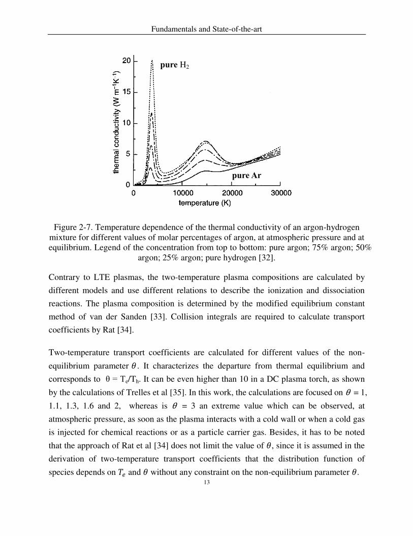
The thermal conductivity of argon-hydrogen mixtures is shown in Figure 2-7. The
thermal conductivity of hydrogen is very much greater than that of argon. Factors that
contribute to this are the − / dependence of the translational thermal conductivity, the
existence of a large reaction thermal conductivity peak associated with the dissociation of
molecular hydrogen, and the generally smaller collision integrals for interactions between
hydrogen species. The presence of a small amount of hydrogen makes a strikingly large
difference to the thermal conductivity at temperatures around 3800 K.
pure Ar
pure H2
Fundamentals and State-of-the-art
13
Figure 2-7. Temperature dependence of the thermal conductivity of an argon-hydrogen mixture for different values of molar percentages of argon, at atmospheric pressure and at equilibrium. Legend of the concentration from top to bottom: pure argon; 75% argon; 50%
argon; 25% argon; pure hydrogen [32].
Contrary to LTE plasmas, the two-temperature plasma compositions are calculated by
different models and use different relations to describe the ionization and dissociation
reactions. The plasma composition is determined by the modified equilibrium constant
method of van der Sanden [33]. Collision integrals are required to calculate transport
coefficients by Rat [34].
Two-temperature transport coefficients are calculated for different values of the non-
equilibrium parameter 𝜃 . It characterizes the departure from thermal equilibrium and
corresponds to θ = Te/Th. It can be even higher than 10 in a DC plasma torch, as shown
by the calculations of Trelles et al [35]. In this work, the calculations are focused on θ = 1,
1.1, 1.3, 1.6 and 2, whereas is θ = 3 an extreme value which can be observed, at
atmospheric pressure, as soon as the plasma interacts with a cold wall or when a cold gas
is injected for chemical reactions or as a particle carrier gas. Besides, it has to be noted
that the approach of Rat et al [34] does not limit the value of 𝜃, since it is assumed in the
derivation of two-temperature transport coefficients that the distribution function of
species depends on 𝑇𝑒 and 𝜃 without any constraint on the non-equilibrium parameter 𝜃.
pure Ar
pure H2

Fundamentals and State-of-the-art
14
In order to illustrate the influence of the non-equilibrium parameter on the plasma
composition, we show in Figure 2-8 the dependence of the number densities of electrons
of an argon-helium mixture (25 mol% Ar) on electron temperature for different values of
non-equilibrium parameter. It can be observed that the electron density becomes almost
constant over 15000 K, and slightly increases, at fixed 𝑇𝑒 as 𝜃 increases. The non-
equilibrium values are always higher than those obtained at equilibrium. Furthermore, the
plasma composition is dominated by the modified Saha equations calculated at 𝑇𝑒, which
favor the ionization of species.
Figure 2-8. Electrons concentration of Ar-He mixture as a function of electron temperature (25 mol% Ar), for different values of θ, at atmospheric pressure [30].
The dependence of the viscosity on 𝜃 is pronounced, as shown in Figure 2-9, which
depicts the viscosity of an argon-helium mixture (25 mol% of argon) as a function of the
heavy species temperature, for different values of the non-equilibrium parameter 𝜃, at
atmospheric pressure. The viscosity has been plotted as a function of heavy species
temperature because it is governed by heavy species. The part of the non-equilibrium
curves which overlap the equilibrium one corresponds to the neutral-neutral interaction
regime before efficient ionization. The study of plasma composition shows that ionization
is especially favored as 𝜃 increases. The significant change in the slope corresponds to
ionization, i.e. the collision integrals of charged species are dominant which drastically

Fundamentals and State-of-the-art
15
reduces the viscosity because the collision integrals of charged species are three orders of
magnitude higher than those of neutral species.
Figure 2-9. Viscosity of Ar-He mixture as a function of heavy species temperature (25 mol% of argon), for different values of the non-equilibrium parameter θ, at
atmospheric pressure [30].
Figure 2-10 shows the electron temperature dependence of the thermal conductivity of an
argon-helium mixture (25 mol% of argon), for different values of the non-equilibrium
parameter 𝜃 , at atmospheric pressure. The main contributions to the total thermal
conductivity are the electron translation thermal conductivity as well as the reaction
thermal conductivity, which depends on ionization reactions (obtained with the modified
Saha equation). As a result, the total thermal conductivity is plotted as a function of 𝑇𝑒.
At low temperatures, the translational contribution of heavy species is dominant. Below
10000 K, it can be seen that, at fixed 𝑇𝑒, the thermal conductivity, depending mainly on
the heavy species temperature, decreases as 𝜃 increases due to a shift of curves plotting.

Fundamentals and State-of-the-art
16
Figure 2-10. Electron temperature dependence of the thermal conductivity of an argon–helium mixture (25 mol% of argon), for different values of the non-equilibrium parameter 𝜃, at atmospheric pressure [30].
2.2 Plasma Spraying
2.2.1 Plasma Spraying Processes
Plasma spraying has been developed since 50 years ago. Praxair, Plasmadyne, Metco and
Plasma Technik, and Thermal Dynamics Corporation are examples of the company to
develop the commercial plasma spraying device [36-38]. The plasma spray process
utilizes a high energy to melt or evaporate feedstock particles, which are injected to
penetrate the plasma torch. Using different spray technology, gas compositions, the
efficient power, the pressure of the process environment, and the feedstock rate yield
different microstructures of coatings deposited.
In the APS process, the feedstock particles are injected into the plasma plume outside the
plasma gun by a carrier gas. An APS coating is deposited by completely or partially
molten particles that impinge on a substrate, spread across the surface, and solidify into
disc-like structures referred to as lamellae. During droplets spreading, the liquid may not
yet wet completely the underlying surface, which will result in inter-lamellar pores.
Adhesion in APS coatings is a result of the interaction of the melted powders with

Fundamentals and State-of-the-art
17
previously deposited layers. SPS differs from APS primarily in that a liquid replaces the
powder carrier gas. This change makes deposited coatings from nanometer-scale
feedstock powders; further details are published [39, 40]. Latest researches of plasma
spraying to control splats coating formation can be found in publications [41]. Two main
parameters control the splat formation: the in-flight treatment of particles behavior and
their interaction with the substrate surface on which they impinge [42-57].
In addition to splats deposition processes, physical vapor deposition methods such as
electron beam physical vapor deposition (EB-PVD) are used to manufacture thermal
barrier coatings [58]. EB-PVD is a process in which a focused high-energy electron beam
is directed to evaporate particles in a high vacuum chamber (~0.05 Pa). The evaporated
material condenses on the surface of the substrate [59]. During deposition, external
heating is used to heat the substrate up to 1500 K for enhancing metallurgical bonding
between the coating and the substrate [60]. EB-PVD is primarily a line-of-sight process;
therefore, continuous rotation of the substrate is applied to deposit coatings of complex
parts like turbine airfoils.
Figure 2-11. The influence of a chamber pressure on the plasma jet [61].
As shown in Figure 2-11, when the plasma spray operates under a reduced chamber
pressure environment of 5-20 kPa, it is known as vacuum plasma spray (VPS). The
combination of further reduced pressure (50-200 Pa) with high gun currents has led to the
development of the plasma spray physical vapor deposition process (PS-PVD).

Fundamentals and State-of-the-art
18
Figure 2-12 presents a schematic of PS-PVD process and a typical resulting columnar
microstructure. PS-PVD is a process in which the feedstock powders are injected into the
inside of plasma torch and are partially or completely evaporated. The evaporated
materials are transported in the plasma jet to deposit columnar structured coatings on the
substrate.
Figure 2-12. Schematic of plasma spray physical vapor deposition process, microstructure of coatings shown in [62].
The PS-PVD equipment used was developed by Oerlikon Metco AG (Switzerland) based
on F4 or O3CP torch with internal power injections. In comparison to atmospheric
plasma spray and vacuum plasma spray up to 90 kW, the PS-PVD process uses a high
energy (up to 180 kW) torch operated at a working pressure below 200 Pa. Under these
conditions, the plasma jet extends in the vacuum chamber reaching lengths up to 2 m and
having a maximum visible diameter of 400 mm. The characteristics of PS-PVD such as
gas compositions and stand-off distance of the sample provide the possibility to deposit a
coating by melting the feedstock particles from liquid splats, but also from vaporized
materials [61]. However, the effect of spray parameters on the microstructure of the
columnar structures is not yet well understood.
Feed Gas
Plasma jet
Plasma Torch
Particle Injector
Cathode(-)
Anode(+)Anode
attachment
Coating
Substrate
Microstructure of coating
Stand-off Distance
Particles (melted or evaporated)

Fundamentals and State-of-the-art
19
Figure 2-13. Cross-sectioned nozzle of an O3CP gun.
Using the converging-diverging O3CP nozzle in the experiments, as shown in Figure 2-
13, the chamber pressure is significantly below the nozzle exit pressure. The plasma jet
exits the nozzle at a supersonic speed. The pressure difference between the nozzle exit
and the chamber pressure leads to the formation of shock diamonds in the flow. In the
downstream direction, the jet adapts to have the same pressure with the chamber. At low
chamber pressure, the environments influence on the plasma jet significantly decreases.
Therefore, the high-energy distribution and different transport properties in the plasma
plume allows the deposition of distinct microstructures of coatings.
2.2.2 Simulations of Plasma Spraying
The modeling of plasma spraying has to consider three main aspects: (1) influences of
carrier gas on the jet dynamics, (2) particles’ melting and diffusion, (3) particles’ evaporation, and (4) coating formation.
The common computational flow dynamics (CFD) approach approximate the fluid
conservation equations of continuity, momentum, species, and energy. The diffusion
phenomena are considered by introducing relations between heat flux and temperature
gradient, or between stress tensor and velocity, respectively. The strategy of CFD is to
replace the continuous simulated domain with a control volume. The control volume
should small enough to capture all relevant local values of the fluid characteristics, as
well as large enough to make the continuum assumption meaningful.
10 um mm

Fundamentals and State-of-the-art
20
Modeling of Plasma Flow Formation 2.2.2.1
The modeling of the plasma torch is highly nonlinear and characterized by its strong
gradients in physical properties. The non-transferred direct current (DC) plasma torch
involves the electrodes, cathode and anode regions, and arc column. The simulations of
the plasma torch have been developed with many assumptions dealing with local thermal
and chemical equilibrium (LTE and LCE). Their predictions give accurate and detailed
results: transient behavior of the arc, prediction of the temperature distribution. However,
the developing of thermal and chemical non-equilibrium (NLTE and NLCE) plasma
torch combined with electrode sheaths are believed necessary for further advances in the
prediction [35, 63, 64].
Near electrodes, the departure from ionization equilibrium and quasi-neutrality can be
modeled by using sheath models to avoid artificial boundary conditions at electrode walls.
Such approach requires at least two-temperature model, characterized by the ratio 𝜃 = 𝑇𝑒 𝑇ℎ⁄ .
The arc-cathode interactions behavior is calculated with imposing the arc current and the
temperature at the rear face of the cathode; then the heat and current density distribution
in the cathode region is calculated; a cathode sheath model is included that predicts the
electron and ion density and temperature at the outer boundary of the sheath as well as
the cathode voltage drop.
The description of the arc column is based on the coupling of fluid and electromagnetic
equations and requires the thermodynamic (density, enthalpy, and specific heat) and
transport properties (thermal and electrical conductivities, viscosity, and diffusion
coefficients) of the gas mixture as well as its radiative properties [35].
The modeling of the plasma formation inside the torch with the surrounding anode has to
address three main issues: (1) the displacement of the arc-anode attachment; (2) the arc
reattachment process; (3) the phenomena at the plasma-anode interface [64].

Fundamentals and State-of-the-art
21
Modeling of Plasma Jets 2.2.2.2
The plasma jet is distinguished into three different areas. The first region corresponds to
the plasma jet core, i.e. the hottest zone which extends depending on a chamber pressure
and in which the ambient penetration is low. In the second region, it acts as the transition
zone toward the turbulence marked by the fast decrease of the plasma temperature
because of the penetration of a chamber gas within the jet. The third region is where the
temperature keeps decreasing as the plasma gas mixes more and more with the
surrounding gas.
The vast majority of plasma jets are turbulent, such as in vacuum plasma spray and
atmospheric plasma spray. Turbulent flows with a wide range of time and length scales
exhibit irregular, random, and chaotic. The turbulence increases the exchange of
momentum in boundary layers. The larger length scale of eddies are in the order of the
flow geometry. The friction forces are larger the smaller eddies. Approximately 90% of
the kinetic energy from larger scales is finally dissipated into eddies of smaller scales
[65]. The turbulence enhances the uniform distribution of the temperature close to the
boundary layer.
The simulation of plasma spray processes requires solving the Navier-Stokes equations
for the continuum flow. Alternatively, the occurring vortices can be calculated using
direct numerical simulation (DNS) that is commonly used to simulate Low-to-medium
Reynolds-number turbulence typical of wind tunnel laboratory experiments [66].
However, it is less accurate and time-consuming. Large-eddy simulation (LES) is a
numerical technique that describes a high-Reynolds number time-evolving and cuts off
the high frequency or small-scale part of the turbulence spectrum [66]. The
computational complexity of the LES models is 20 times higher than that of RANS
simulations and substantially lower than that of DNS.
However, it is difficult to implement microscopic interactions into the macroscopic
Navier-Stokes equation. In the other side, plasma jets with particles injection refer to one
of the most complex flows, namely for its multiphase character during spraying. This
includes interface instability, wetting dynamics, interfacial slip, and evaporation of
particles [67]. Simulating these kinds of flows has always been a challenge to

Fundamentals and State-of-the-art
22
conventional CFD because of the moving and deformable interfaces between phases or
components originating from the specific interactions among the flow. The lattice
Boltzmann method (LBM) is considered versus classical approaches to solve complex
problems of heat and fluid flow. Its time-dependent scheme is in accordance with
unsteady plasma jet [68, 69]. In LBM, the particulate kinetics provides a relatively easy
way to incorporate the microscopic interactions by modifying the collision operator.
Plasma jet and plasma spraying for a multiphase/multicomponent flow can be done by
LBM simulation and modeling [70, 71]. It is generated automatically from the particle
dynamics and no special treatment is needed to manipulate the interfaces as in traditional
CFD methods. The LBM scheme is also employed for simulating the turbulent plasma
flow in coupling with the mass, momentum and energy conservation equations [72, 73].
Moreover, LBM contains more physical connotation than Navier-Stokes due to the
application of a mesoscopic discrete Boltzmann equation to describe the flow. However,
an introduction of sound speed reduction is treated by LBM model is needed to simulate
a compressible flow [74].
Three-dimensional simulation of plasma torch with asymmetric temperature and velocity
distributions at the nozzle exit, which are obtained from the plasma arc model, to clarify
the three-dimensional effect of nozzle exit profiles on the plasma jet characteristics [75].
Standard K- model is used to account the turbulent characteristics of the plasma jet. It is concluded that plasma jet velocity shows stronger three-dimensional effect than
temperature.
K. Bobzin et al [76] has shown the flow characteristics of atmospheric plasma jets
generated by means of a three-cathode spraying system. Among all RANS models
investigated in this study, the SST turbulence model yielded the best agreement with LES.
SST turbulence and k-ω revealed similar results for free flows. At wall-boundaries, k-ω models showed a satisfactory accuracy. The focus was placed on to the turbulence and
diffusion/demixing modeling. The author also has shown that the significance of
diffusion-driven mixing is negligibly small in comparison with that of turbulence-driven
mixing for plasma spraying. Numerical calculations related to the comparisons of
between turbulent and laminar plasma jet have been published [77-87]. It can be

Fundamentals and State-of-the-art
23
summarized that the entrainment of surrounding cold gas into the plasma jet is
detrimental in terms of particle melting as well as particle acceleration.
Modeling of the Particles Treatment in Plasma Jets 2.2.2.3
The modeling of the plasma jet has advanced greatly in the last 15 years due to a better
understanding of the underlying physics, development of computational fluid dynamics
software and access to high performance and cloud computing. The fluid dynamics and
properties of the plasma jet is controlled by the plasma formation, dynamic behaviors of
the arc, melting, evaporation and vaporization of feedstock particles and the coating
formation [88, 89], while the interactions between the feedstock particles and the plasma
are not completely understood yet. Particularly, in the PS-PVD process, feedstock
particles are introduced to the inner side of the torch.
The particle trajectory within the high-energy plasma jet depends on its acceleration of jet
flow on it. This acceleration is proportional to the flow velocity and viscosity, but
inversely related to the specific mass and diameter of the particle. The heat transfer
mechanisms between the hot flow and a single particle is determined by convective
heating and radiative losses of the particle. To obtain completely evaporation of a particle,
the energy transferred by the plasma onto the particle during the residence time must be
larger than the energy required for heating, melting and evaporating the particle. There
are reveal possibilities to increase the heat transfer to the particle [90]: (1) enhanced heat
transfer coefficient (higher thermal conductivity), (2) increased residence time of the
particle in the plasma, (3) raised plasma temperature, (4) reduced particle diameter.
Hong-Bing Xiong et al [91] has shown the melting behavior of in-flight particles in
plasma spray process.
Coatings applied via atmospheric or vacuum plasma spraying are composed of splats
which emerge when semi-molten and molten powder particles which are deposited on the
substrate, while coatings produced by PS-PVD consists of columnar structures.
Characteristic of particles state involved in the coating formation, i.e., their temperatures,
velocities, diameters, and melting or evaporation index, determine the performances of
the coatings. The above-mentioned properties of particles greatly depend on the heat and
momentum transfer between plasma jet and feedstock particles. Comprehensive recently

Fundamentals and State-of-the-art
24
literature reviews on the modeling of the plasma spraying have been published [76, 92-
101].
The computation of particles’ velocities, temperatures, and trajectories without
consideration of evaporation is shown in [102]. The only viscous drag force acting on a
particle was considered as the only driving force. The motion of particles is governed by
Newton’s second law, which, after integration, gives the trajectory. Due to the consideration of carrier gas influence, the particles are more dispersed.
P. Fauchais [103] presents developments in direct current plasma spraying of suspensions.
It explains the interactions between the liquid feedstock with sub-micrometric particles
and plasma jet, and concludes by linking the coating microstructure with the liquid
processing the plasma jet. K. Pourang [104] studied suspension plasma spray both
experimentally and numerically. A two-way coupled Eulerian-Lagrangian approach was
solved by ANSYS Fluent software. The suspension was modeled as a multi-component
droplet that undergoes break up and evaporation. At the standoff distance of 50 mm,
plasma axial velocity was found to be around 800 m/s and plasma temperature was
calculated to be about 3500 K. A large body of literature published related to suspension
plasma spraying since 2010 [39, 40, 105-113].
2.3 Coating Deposition
2.3.1 Thermal Barrier Coatings
Thermal barrier coatings (TBCs) are increasingly being applied to the surfaces of metallic
parts in the hottest part of gas-turbine engines [114, 115]. Yttria-stabilized zirconia (YSZ)
is still the state-of-the-art ceramic material for TBC applications. While the coating
provides a thermal barrier, it does not block oxidation of the underlying metal, because
ZrO2 is a fast oxygen-ion conductor at high temperatures. As a result, an oxide (termed
thermally grown oxide, TGO) gradually grows at the interface between the metal and the
coating. Indeed, the bond coat is applied to the metal prior to the deposition of the
thermal barrier coating. It promotes the formation of a highly stable, protective aluminum
oxide phase during oxidation. Figure 2-14 illustrates the structure of TBCs. The
Fundamentals and State-of-the-art
25
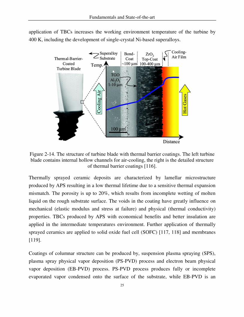
application of TBCs increases the working environment temperature of the turbine by
400 K, including the development of single-crystal Ni-based superalloys.
Figure 2-14. The structure of turbine blade with thermal barrier coatings. The left turbine blade contains internal hollow channels for air-cooling, the right is the detailed structure
of thermal barrier coatings [116].
Thermally sprayed ceramic deposits are characterized by lamellar microstructure
produced by APS resulting in a low thermal lifetime due to a sensitive thermal expansion
mismatch. The porosity is up to 20%, which results from incomplete wetting of molten
liquid on the rough substrate surface. The voids in the coating have greatly influence on
mechanical (elastic modulus and stress at failure) and physical (thermal conductivity)
properties. TBCs produced by APS with economical benefits and better insulation are
applied in the intermediate temperatures environment. Further application of thermally
sprayed ceramics are applied to solid oxide fuel cell (SOFC) [117, 118] and membranes
[119].
Coatings of columnar structure can be produced by, suspension plasma spraying (SPS),
plasma spray physical vapor deposition (PS-PVD) process and electron beam physical
vapor deposition (EB-PVD) process. PS-PVD process produces fully or incomplete
evaporated vapor condensed onto the surface of the substrate, while EB-PVD is an

Fundamentals and State-of-the-art
26
atomistic deposition process. As to SPS, particles are dispersed in the solvent to decrease
the size of the original particles, and then are injected into the plasma jet. After the
solvent vaporization, melted particles spread over the substrate in the same way as for
APS. Nevertheless, SPS requires lower stand-off distances (for example 50 mm) to void
re-solidification of nanoparticles.
2.3.2 Growth Mechanisms of Columnar Microstructures
In SPS process, a higher proportion of smaller splats (average diameter ~ 3.3 𝜇 )
facilitate the deposition of columnar YSZ coatings described by Chen et al [120]. High-
magnification SEM images indicate that SPS YSZ intra-columns have a similar
microstructure to conventional APS coatings, but with much thinner lamellar thickness.
The substrate surface roughness has a strong influence on the SPS coatings. The rougher
the substrate surface, the less uniform the coating that could change from free of vertical
cracks and columns to deep vertically cracked (DVC), and even to columnar. A rougher
substrate surface lead to a higher drag force level by the plasma gas flow, which make
fine SPS droplets with a higher lateral impinging velocity resulting in a high potential to
develop columnar structures on the substrate with a roughness [121]. As shown in Figure
2-15(a), SPS coating porosity presents a uniform distribution in space within the layer
thickness compared to EB-PVD coating for which porosity is mainly located in the fringe
of the columns.
The diameter of the columns of EB-PVD YSZ coatings starts from less than 2-3 μm on
the substrate surface and increases at the column tip to 10-20 μm [122]. These columns
are mainly separated by inter-columnar gaps. Inter-columnar gaps are a few nanometers
width close to the substrate and can be large as 1 μm at the coating tip. The high thermal
shock-resistance of the EB-PVD processed TBCs is a result of the presence of these inter-
columnar gaps. Most of the open porosity originates from the voids present between
nano-sized secondary columns, so-called feather-arms, growing at the column edges, as
shown in Figure 2-15(b). These are formed mainly by shadowing, depending on the
rotation speed, the substrate temperature and the angle between the substrate and incident
vapor. Due to the interruption of the vapor deposition during rotation, intra-columnar
voids are created in form of channel-like pores. It should be mentioned that EB-PVD

Fundamentals and State-of-the-art
27
generally produces qusai-single crystalline columns with a predominantly <100>
orientation [120].
Figure 2-15. Intra-columnar porosity in SPS (a) and EB-PVD (b) coatings [121].
2.3.3 Microstructures Produced by Plasma Spray Physical Vapor Deposition
The PS-PVD coatings are commonly splat-like or columnar, deposited from molten
feedstock particles and feedstock vapors, respectively [4, 123-127]. These two types of
microstructures are related to different plasma energies and compositions. Heat transfer
to particles injected in the flow occurs mainly by conduction through the boundary layer
surrounding particles. The heat flux, of course, follows the same trend as the thermal
conductivity of the plasma [128]. If the heat transfer is much higher with appropriate
plasma gas mixtures, for example 35Ar-60He, zirconia can efficiently evaporate, and the
structure of the deposited coating is columnar that is similar to columns produced by EB-
PVD [60]. Figure 2-16 shows the microstructure deposited by PS-PVD. The vaporization
degree of the powder can be controlled by the plasma gas composition and the powder
feed rate [129, 130].
100Ar-10H2 plasma yield a very low degree of vaporization due to low temperature, as
shown in the top graph of Figure 2-16. Consequently, a high powder feed rate can result
in splat-deposition. Hydrogen dissociation consumes a remarkable portion of energy that
will lead to a significantly lower maximum temperature of the plasma jet. The slight

Fundamentals and State-of-the-art
28
increase of the temperatures at the substrate surface are associated to the release of the
dissociation energy.
Hot 35Ar-60He plasma combining with a low feedstock rate yield a high degree of
vaporization, which leads to a real vapor deposition which is comparable to the coatings
by EB-PVD, as shown in bottom graph of Figure 2-16. The middle graph of Figure 2-16
shows that a high feedstock rate results incompletely evaporated particles (clusters).
Figure 2-16. SEM images produced by PS-PVD at different parameters, the left is morphology of YSZ particles, the middle is the resultant microstructures for different feeding rate, and the right is the detailed microstructures corresponding to the middle
[129].
Optical emission spectroscopy (OES) is used to verify the influence of specific plasma
parameters with the injected ceramic materials on the resulting microstructures. Figure 2-
17(a) shows the spectrum of the plasma jet with injected YSZ powders that produce
splat-like coatings. The intensity of the spectral lines coming from the YSZ species is low,

Fundamentals and State-of-the-art
29
which presents that only a minor amount of the coating material is evaporated. In Figure
2-17(b), the spectrum shows an increased overall intensity of the spectral YSZ lines
which cover the full-wavelength bandwidth of the spectrometer (350-900 nm). The
spectral lines correspond to the different species contained within the YSZ, namely,
zirconium and yttrium. Here, the injected material could be vaporized which allows the
growth of columnar-structured coatings.
A typical EB-PVD 7YSZ TBC microstructure in polished cross section can be seen in
Figure 2-18(a). EB-PVD produced coatings consist of a quite homogeneous columnar
structure composed of compact single columns. The bulk structure is characterized by
inter-columnar gaps and voids between feathery structures. In contrast, PS-PVD
produced coatings consist of many fine needles with a high amount of internal porosity,
as shown in Figure 2-18(b).

Fundamentals and State-of-the-art
30
Figure 2-17. Optical spectrum of the plasma jet (Ar/He) with 7YSZ corresponding to coatings having (a) no columnar structure and (b) with columnar structure [5].

Fundamentals and State-of-the-art
31
Figure 2-18. Typical EB-PVD 7YSZ TBC microstructure in cross section (a) and columnar TBC top layer deposited with PS-PVD on a MCrAlY bond coat (b) [131].
2.4 Modeling of Columnar Microstructure Formation
Monte Carlo methods start with random inputs from a probability distribution then
perform a deterministic computation on the inputs to obtain numerical results. An
overview on the Monte Carlo model for simulating microstructural evolution can be
found in [132-139].
The morphology of the depositing film is determined by the characteristics of the incident
vapor or droplets, the surface roughness, and the surface mobility of the deposited atoms,
the presence of geometrical shadowing and surface diffusion [140]. The EB-PVD
coatings with preferential crystal orientation deposit from atomically dispersed vapor
plume at a very low deposition rate [141, 142]. Deposition rates up to 240 μm/min of PS-
PVD process result in no prominent crystal orientation, except for at specified high
temperature near the substrate [61]. Two-dimensional Monte Carlo simulations have been
(a) (b)

Fundamentals and State-of-the-art
32
conducted to provide insight on the evolution of columns [143, 144]. This model is
implemented on a molecular scale that incorporates the effect of self-shadowing.
The respective columnar microstructures forming in PVD layers are controlled by self-
shadowing, surface diffusion, and bulk diffusion as substrate temperature increases [145].
This porous columnar structures form when the titled incident vapor phase particles
impinge on a substrate and insufficient diffusion does not overcome the influence of the
self-shadowing [146]. As the substrate temperature increases surface diffusion is
activated. The columns evolution from densely, well-defined microstructure to equiaxed
grains with recrystallization occur as the further increase of temperature to activate the
possibility of bulk diffusion [147, 148].
Y.G. Yang [137] utilized a kinetic Monte Carlo (KMC) method to simulate void
evolution of a zig-zag coatings. The pore morphology strongly depends on the incident
vapor flux distribution. Theron M. Rodgers [136] quantifies the simulation of nickel
coatings with those from experimental depositions. The author investigates high vacuum
physical vapor deposition to predict variations in coating thickness, columnar growth
angle, and porosity during both stationary and substrate rotated deposition.
Deposition rates by the PS-PVD process are two scales higher than those that of EB-PVD
process [123, 149]. When the deposition rate is low, particles (gases, molecules or
clusters) migration is possible. The probability of diffusion to the shadowed areas occurs
when the jump attempt time is smaller than the time interval between particles arrivals at
low deposition rate, or when at high substrate temperatures the energy barrier is low for
possible diffusion. Even though a numerical simulation of columnar microstructures in
EB-PVD process by Monte Carlo technique with consideration of self-shadowing and
kinetic diffusion [136, 137, 150], the simulation of columnar microstructures in PS-PVD
process including self-shadowing is rare. The PS-PVD process has also been proved to
deposit coatings on the shadowed areas of the substrate [129].
2.4.1 Effect of Adatom Surface Mobility
Typically, the film near the interface is influenced by the substrate and or interface
material and it takes an appreciable thickness before the film establishes a particular

Fundamentals and State-of-the-art
33
growth mode. After a growth mode has been established, the film morphology can be
described by a structure zone model (SZM), as shown in Figure 2-19. The SZM was first
applied to vacuum-deposited coatings by Movchan and Demchishin (MD) in 1969 [136].
Later, the SZM was extended to sputter-deposited films by Thornton [151], and later
modified by Meissier [145] to include point defect agglomeration and void coarsening
with thickness.
Figure 2-19. (a) Structure zone model for thin films deposited by physical vapor deposition [151, 152]. The x-axis shows the deposition temperature 𝜃 = 𝑇 𝑇⁄ . (b)
Corresponding schematic for layers deposited by glancing angle deposition, showing rods (r), columns (c), protrusion (p), equiaxed grain (e), and whiskers (w) [153].
Shadowing controls the film microstructure and texture in Zone I, and the film is
columnar with tapered voids between columns. In Zone II, surface diffusion is the
Fundamentals and State-of-the-art
34
leading process that controls the morphological evolution, and the film consists of
columnar grains with defined dense grain boundaries, faceted top surfaces, and an
increased grain width. In Zone III, the microstructure is governed by bulk diffusion, and
the microstructure exhibits equiaxed grains.
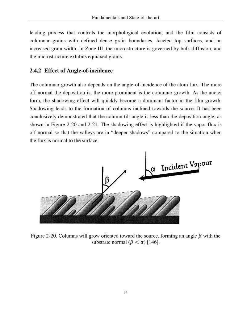
2.4.2 Effect of Angle-of-incidence
The columnar growth also depends on the angle-of-incidence of the atom flux. The more
off-normal the deposition is, the more prominent is the columnar growth. As the nuclei
form, the shadowing effect will quickly become a dominant factor in the film growth.
Shadowing leads to the formation of columns inclined towards the source. It has been
conclusively demonstrated that the column tilt angle is less than the deposition angle, as
shown in Figure 2-20 and 2-21. The shadowing effect is highlighted if the vapor flux is
off-normal so that the valleys are in “deeper shadows” compared to the situation when the flux is normal to the surface.
Figure 2-20. Columns will grow oriented toward the source, forming an angle with the substrate normal ( < ) [146].

Fundamentals and State-of-the-art
35
Figure 2-21. Plot of four different analytic curves relating the column tilt angle and the deposition angle [146].
2.4.3 Effect of Substrate Parameters
Diffusion and Surface Temperature 2.4.3.1
Surface diffusion counteracts the effect of shadowing. Fick’s law, moving adatoms from
the columns tips toward the shadowed areas, governs the diffusion. Surface diffusion can
be considered as a thermally activated Arrhenius-type process. The displacement of the
adatoms over the substrate surface is proportional to √ 𝑡 ( the diffusion coefficient, 𝑡
the diffusion time). Surface diffusion is linked to the substrate temperature and the
deposition rate. Higher temperatures and slow deposition rate (EB-PVD) will increase the
diffusion distance, whereas lower temperatures and rapid deposition (PS-PVD) will limit
diffusion.
Roughness of the Substrate Surface 2.4.3.2
VanEvery et al [108] proposed that the column size of column formation in SPS YSZ
coatings is strongly influenced by the surface topography. Small droplets of 1 μm, their

Fundamentals and State-of-the-art
36
deposition trajectory will follow the parallel flow to the surface for some distance before
they impact a surface asperity. Thus, the individual columns form by progressive built up
of particulates on surface peaks. Smoother surfaces tend to generate a higher density of
columns. When the surface is rough, the peaks receive the adatom flux from all directions
and, if the surface mobility of the adatoms is low, the peaks grow faster than the valleys
due to geometrical shadowing.
Park et al [154] reported that the roughness of the substrate affected the growth behavior
of the EB-PVD YSZ coatings, but has not found any evident influence on the width of
columns. Smooth surface areas lead to regular and uniform columns. Dense and inclined
columns are deposited at a rough area due to non-uniform distribution of atomic vapor
flux resulting from diffusion. Therefore, the film growth behavior can be different at
different location of the surface.

Theoretical Methods
37
3 Theoretical Methods
3.1 The Plasma Jet Modeling
3.1.1 Assumptions
The simulation of the plasma jet is based on the following assumptions:
The jet can be represented by a 2D axis-symmetrical flow field;
The plasma is in chemical and the thermodynamic equilibrium;
The condition of quasi-neutrality holds;
The plasma is optically thin, the emission coefficients and the observed intensities
are directly proportional;
The plasma gas and chamber gas have the same composition;
Gravitational effects are considered to be negligible;
Arc dynamics influence on the plasma jet is not considered, therefore, the
amplitude of the temperature and velocity at the nozzle exit is a 2D time-averaged
value and validated by net power.
3.1.2 Mathematical Modeling
The computational domain is displayed in Figure 3-1. The plasma jet is treated as a
compressible, reacting with temperature-dependent thermodynamic and transport
properties with the assumption of local thermodynamic equilibrium. The plasma jet is
described as a symmetrical, two-dimensional geometry. Detailed descriptions of the
governing equations for the mass, momentum and energy conservation equations for the
plasma mixture can be found in literature [140].
Plasma gas leaves the plasma torch at the nozzle outlet at high temperatures and
velocities. The temperature is verified by the efficient power. In the laminar flow, the
flow is dominated by the object shape and dimension (large scale). In the turbulent flow,
the flow is dominated by the object shape and dimension and by the motion and evolution
of small eddies (small scales). Turbulent flow is chaotic, random, and irregular.

Theoretical Methods
38
Particularly, the boundary layers and the wakes around and after the substrate are
turbulent.
The continuity equation for the mass, momentum and energy conservation equations for
the flow used to model the plasma jet is based on Navier-Stokes equations. Two-equation
models Shear-Stress Transport (SST) k-ω model are used that shows a satisfactory
accuracy to model the walls. It was developed by Menter [155]. The simulation of the
plasma jets in the steady-state are solved by pressure-based coupled solver [156]. In the
case of slip flow, Dmitrii Ivchenko et al has shown the continuum breakdown of the flow
at very low pressure plasma spray conditions [157].
The temperature and pressure dependent thermodynamic properties of the plasma gas are
required in the literatures [158]. The transport property (viscosity and thermal
conductivity) data is used in the NASA Lewis Research Center’s Chemical Equilibrium and Applications Program (CEA). It complements transport property coefficients are
independent of pressure.
3.1.3 Geometry and Boundary Conditions
The computational domains with its geometrical dimensions are composed of nozzle
(torch region) and chamber where the plasma jets extend, as illustrated in Figure 3-1.
Table 3.1 summarizes boundary conditions of the computational domains. The boundary
conditions include the nozzle wall and a chamber wall. Nozzle wall represents the wall of
the water-cooled anode, defines as a no-slip wall at a constant temperature of 350 K.
Nozzle inlet means plasma forming gas inlet where the composition of feedstock gases
are obtained from [159], and is defined as mass flow inlet with a high constant
temperature adjusted to the efficient power in the nozzle exit of 60 kW [160]. Pressure
outlet at a constant value means boundaries of a chamber ranging from 200 Pa to 10,000
Pa are used according to the case studied. The plasma spray operating parameters are
summarized in Table 3.2.

Theoretical Methods
39
Figure 3-1. The computational domain.
Table 3.1. Boundary conditions
Boundary conditions
Nozzle wall No-slip wall
Nozzle inlet Mass flow inlet
Chamber wall Pressure outlet
3.2 Plasma Composition
Compositions of two-temperature plasmas in local chemical equilibrium (LCE) were
derived following by the minimization of Gibbs free energy [161-163], or by Potapov’s method [164, 165], or by kinetic calculation [166], or by Van de Sanden et al [33, 164].
The plasma is considered to be in local thermodynamic equilibrium (LTE) when the
Maxwell-Boltzmann distribution describes the kinetic energies of each species, the
Boltzmann distribution describes the excited states, mass action laws describe the species
densities. LTE allows the conservation equations (of mass, momentum, and energy),
provided the thermodynamic state of the plasma and the transport coefficients.
The plasma is assumed to be in chemical equilibrium; therefore, according to the
assumptions in section 3.1, its composition is determined by the minimization of Gibbs
free energy, the quasi-neutrality condition and Dalton’s law of partial pressures [12]. For
an Ar-He-H2 plasma and the temperatures considered in this study, the plasma is
primarily composed of eight species (i.e. He, He+, H2, H, H+, Ar, Ar+, and e-). In PS-PVD
2000 mmNozzle
Chamber
Pressure outlet
Pressure outletPressure outletPlasma gas inlet
Nozzle wall
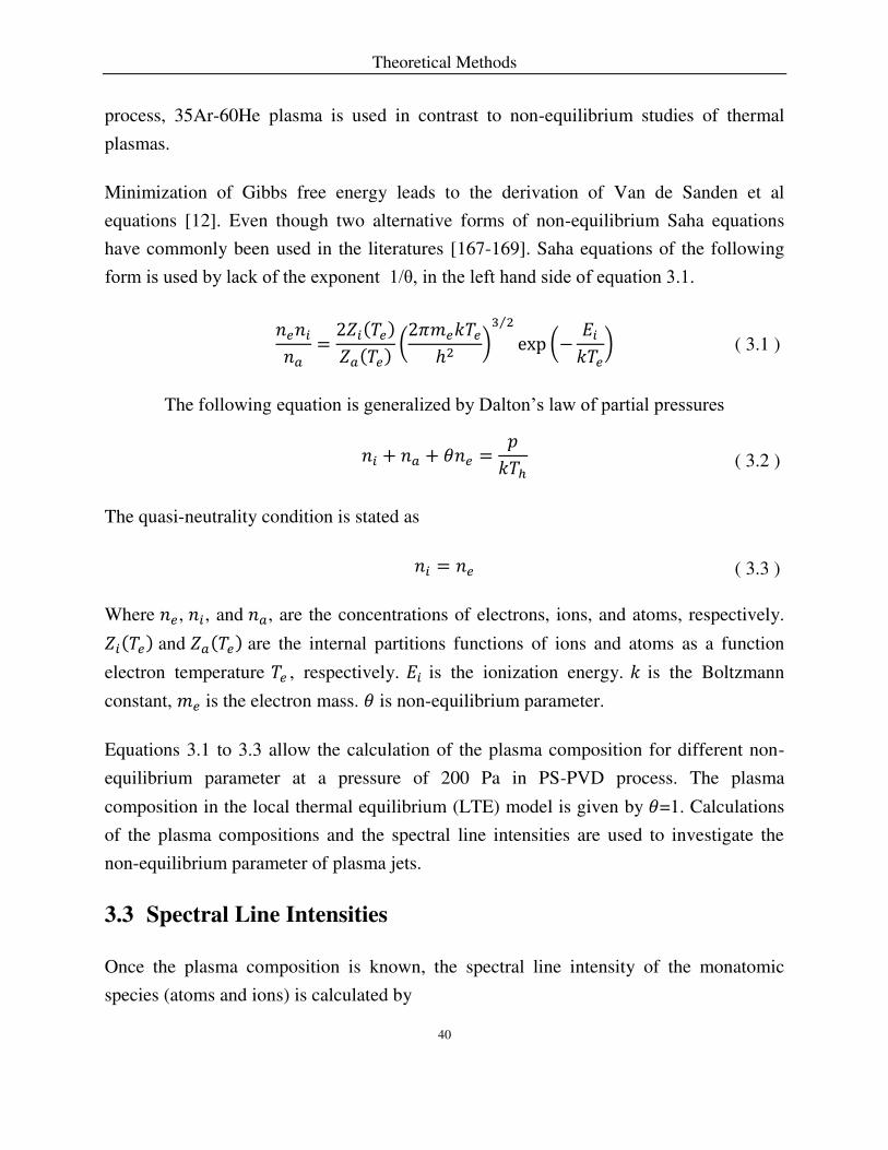
Theoretical Methods
40
process, 35Ar-60He plasma is used in contrast to non-equilibrium studies of thermal
plasmas.
Minimization of Gibbs free energy leads to the derivation of Van de Sanden et al
equations [12]. Even though two alternative forms of non-equilibrium Saha equations
have commonly been used in the literatures [167-169]. Saha equations of the following
form is used by lack of the exponent 1/θ, in the left hand side of equation 3.1.
𝑒𝑎 = 𝑍 𝑇𝑒𝑍𝑎 𝑇𝑒 ( 𝜋 𝑒 𝑇𝑒ℎ ) ⁄ exp (− 𝑇𝑒) ( 3.1 )
The following equation is generalized by Dalton’s law of partial pressures
+ 𝑎 + 𝜃 𝑒 = 𝑝𝑇ℎ ( 3.2 )
The quasi-neutrality condition is stated as
= 𝑒 ( 3.3 )
Where 𝑒, , and 𝑎, are the concentrations of electrons, ions, and atoms, respectively. 𝑍 𝑇𝑒 and 𝑍𝑎 𝑇𝑒 are the internal partitions functions of ions and atoms as a function
electron temperature 𝑇𝑒 , respectively. is the ionization energy. is the Boltzmann
constant, 𝑒 is the electron mass. 𝜃 is non-equilibrium parameter.
Equations 3.1 to 3.3 allow the calculation of the plasma composition for different non-
equilibrium parameter at a pressure of 200 Pa in PS-PVD process. The plasma
composition in the local thermal equilibrium (LTE) model is given by 𝜃=1. Calculations
of the plasma compositions and the spectral line intensities are used to investigate the
non-equilibrium parameter of plasma jets.
3.3 Spectral Line Intensities
Once the plasma composition is known, the spectral line intensity of the monatomic
species (atoms and ions) is calculated by

Theoretical Methods
41
𝐼 λ = 4𝜋 ℎ𝑐λ 𝐴 𝑍 𝑇𝑒 −𝐸𝑚/ 𝑇𝑒 ( 3.4 )
Where ℎ is the Planck’s constant, 𝑐 is the speed of light, 𝐴 is the transition probability, λ is the wavelength between the upper level and lower level , is the statistical
weight, is the energy of the upper level, is the total concentration of the species ,
and 𝑍 𝑇𝑒 is the internal partition function calculated at electron temperature 𝑇𝑒. These
parameters are taken from the NIST atomic spectra database [170].
3.4 Monte Carlo Simulation of Columns Growth
3.4.1 Assumptions
Two-dimensional Monte Carlo simulation of columns growth in the PS-PVD process is
based on the following approximations:
1. Surface and bulk diffusion is neglected due to the fast deposition rate;
2. Particle coagulation is neglected;
3. No collisions between incident vapor particles;
4. The effect of self-shadowing on the columns growth is considered;
3.4.2 Two-dimensional Computational Procedure
A Monte Carlo algorithm is used to simulate the deposition of particles in two
dimensions [143]. The modeling is conducted using a 5000×1000 ( × pixels) grid with
periodic boundary conditions. The modeling include two steps to investigate the
formation of columnar microstructures: Firstly, the incoming particle deposits on the
substrate surface considering shadowing, Then, the newly deposited particle relaxes to a
stable site.
A sketch of the deposition process explains the computational procedure, which is shown
in Figure 3-2. Each square represents one particle position. It is possible to grow in the x-
direction and y-positive direction. Particles are allowed to deposit at free site. The bottom
represents the surface of substrate, represents the incident angle of the vapor flux

Theoretical Methods
42
relative to the substrate normal. The pair of seeds is used to make sure that a newly
deposited particle has at least two neighborhoods.
Figure 3-2. A sketch of the deposition process. The width and height of mesh are 5000×1000 ( × pixels). The bottom represents the surface of substrate. The marked
area (analyzed area) in red dash line is used to calculate porosity. “Steps =3’ means that one free sites at the beginning of simulation. The arrow is the direction of incoming particles. Self-shadowing refers to along the trajectory of incoming particles position
particle (i) can not grow due to a previously deposited particle (k) blocks the incoming flux.
Before the deposition begins, a pair of seeds occupy the substrate sites of the simulation
cell for different seed distances (steps are assumed as 2 or 10, if substrate is planar, = ), whereas the rest of the lattice is empty; each particle is dropped from a randomly
chosen position at a height 1000 with a random traveling angle relative to the
substrate normal following the normal distribution (𝜇, 𝜎) in Figure 3-3. Injecting vapor
particle travels along a straight line (assuming no collisions occur with other gas atoms)
towards the substrate in the direction of the vapor flux (varying between -90° and 90°).
Subsequently, particles are allowed to deposit on any of the exposed surface of an already
k
i
y
x
Incoming particles
Steps =3
600 pixels
300 pixels
100 pixels

Theoretical Methods
43
deposited particle. All new particles are assumed to bind with the other already deposited
particles after checking the surrounding neighbors to establish the newly deposited
particle having at least two neighboring sites along the direction of the incoming particle.
The diagonal neighbors are considered so that a deposited particle can have maximum 8
neighboring sites. As shown in Figure 3-2, we use already deposited particle k as an
example, if a newly traveling particle with a angle relative to the substrate normal, it
deposits on the top position of the particle k, then checking it neighbors and finding a
position at the left of the particle k with two neighbors, finally the newly coming particle
will deposit in the left position of the particle k.
Figure 3-3. Normal distributions of incoming vapor flux ranging from -90° to 90°.
The averaged porosity is calculated in the marked area of the deposition process. The influence of distance of seeds and top free-space are ignored. It refers to only the bulk area of columns considered. The orientation of columns is analyzed by averaged-angle of different titled columns.
0
0.01
0.02
0.03
0.04
0.05
-90 -60 -30 0 30 60 90
Pro
ba
bil
ity
a(degree)
μ= °, σ= °
μ=3 °, σ=3 °
μ= °, σ= °

Experimental Methods
44
4 Experimental Methods
4.1 PS-PVD Equipment
Plasma spraying was employed on a Oerlikon Metco PS-PVD Multicoat System with the
O3CP gun (Switzerland). Images of plasma jets were taken depending on chamber
pressures ranging from 200 Pa to 10,000 Pa to compare to my simulated results and a
power input of 120 kW were used in the experiment. The net power was 60 kW.
Figure 4-1. The process of optical emission measurement.
4.2 Plasma Jet Characterization
In order to validate the calculated spectral line intensities, Optical Emission Spectroscopy
(OES) that has been done by the peer PhD-candidate Wenting He, they are compared it to
the measured integrated spectral line intensities. OES is used as a common technique to
determine the relative spectral line intensities for atoms and ions in the UV/visible range.

Experimental Methods
45
For plasma characterization, the spectrometer applied for plasma characterization was an
ARYELLE 200 (Laser Technik Berlin (LTB), Berlin, Germany) scanning a wavelength
range of 381-786 nm. Plasma radiation was collected through a borosilicate glass window
and an achromatic lens, transferred by an optical fiber to the 50 μm entrance slit and detected by a 1024x1024 CCD array. The system was equipped with an Echelle grating
and the spectral resolution obtained is 15.9-31.8 pm [160]. In the experiment of the OES
measurement, the integrated relative intensity was measured as a function of radial
distance (0 mm -100 mm) at the axial stand-off distance of 1 m at a chamber pressure 200
Pa, as shown in Figure 4-1.
Table 4.1. The plasma spray operating parameters
Plasma gun operating conditions
Nozzle exit diameter, mm 20
Current, A 2750
Effective power, kW 60
Plasma gas flow rate Ar/He, slpm
Plasma gas flow rate Ar/He/H2, slpm
Plasma gas flow rate Ar/H2, slpm
35/60
35/60/10
100/10
Chamber pressure, Pa
Spray distance, mm
200-10000
1000
slpm (stand liter per minute)
4.3 Coating Characterization
The PS-PVD process for a 35Ar-60He plasma mixture with YSZ powder injected
operates at a chamber pressure of 200 Pa. The net power of the process is 60 kW. Two
types of coatings were produced by PS-PVD, in which two orientations (horizontal and
vertical) towards the axial center of the plasma jet are used at the stand-off distance of 1m.
Cross-sections of the PS-PVD coatings were observed by a scanning electron microscope

Experimental Methods
46
(TM3000, Hitachi High Technologies Europe GmbH, Krefeld) and surface morphology
was investigated with Lasermicroscope-Cyberscan (VK9700, Keyence Germany GmbH,
Neu-Isenburg, Germany). The main aim of the two substrate orientations is to evaluate
the deposited coating structures.
Results and Discussions
47
5 Results and Discussions
5.1 Thermodynamic and Transport Properties
The thermodynamic (specific heat, enthalpy, and entropy) and transport (viscosity and
thermal conductivity) property data provided with the CEA program are given as
functions of temperature as high as 20000 K in the form of least-squares coefficients
[158]. The minimization-of-free-energy formulation is used to describe the chemical
equilibrium in the CEA program [171]. Zeleznik [172] presents equations based on
minimization of Gibbs energy.
For the monatomic gases (Ar and He), when temperature increases, first the density of
argon or helium decreases following the ideal gas law, and then progressively ionization
takes place. Figure 5.1 presents the compositions for 35Ar-60He-10H2 plasma at the
pressure of 200 Pa. At 5000 K for Ar the ion density is four orders of magnitude lower
that that of the neutral species, and it becomes higher than that of neutral species only at
about 10000 K. No Ar2+ ions show up for T<20000 K while the density of Ar is 1x10¹⁶
against 1x10²⁰ m-3 for Ar+ at 20000 K. For helium, due to the higher ionization potential
(24.5 eV against 15.8 eV for Ar), the same phenomena (nHe=104nHe+ and nHe=nHe+) occur
at 11000 K and 16000 K, respectively. Hydrogen behaves differently: first the molecule
has to be dissociated (dissociation energy 4.6 eV), which is completed at 5000 K, before
ionization of the atomic species occurs. As the ionization energy is close to that of Ar
(13.6eV against 15.8 eV for Ar), ionization is completed at about the same temperature as
for Ar.

Results and Discussions
48
Figure 5-1. Evolution of molar densities of a 35Ar-60He-10H2 plasma versus temperature at the pressure of 200 Pa.
5.1.1 Ar-He Plasma Mixture at High Pressures
The thermodynamic and transport property are calculated based on CEA program, which
uses the minimization-of-free-energy formulation for assigned temperature and pressure.
Temperature and pressure follow the kinetic theory. The interaction among species is
neglected.
Figure 5-2 and 5-3 show the enthalpy and specific heat capacity of 35Ar-60He plasma
mixture at different pressures. At a given temperature, the enthalpy of a gas increases as
the pressure decreases due to the lower ionization temperatures; a great deal of energy is
needed to ionize a gas, and thus the energy content is higher at temperatures exceeding
the ionization level. It can be seen that when the pressure increase, the successive peaks
of specific heat capacity corresponding to argon ionization, helium ionization, and
ionization is shifted to higher temperatures. The maximum values of the peaks decreases
with the increase of the pressures.
0 5000 10000 15000 200001015
1016
1017
1018
1019
1020
1021
1022
1023
Co
nce
ntr
atio
n (
m-3
)
Temperature (K)
Ar
Ar+
e
H
H+
H2
He
He+

Results and Discussions
49
Figure 5-4 and 5-5 present the viscosity and thermal conductivity of 35Ar-60He plasma
mixture at different pressures. In this theory, viscosity is independent of pressure. The
apparent paradox of the independence of viscosity with the pressure can be explained as
follows. If the concentration of atoms is halved, a half concentration of atoms available to
transport momentum, but the mean free path of each atom is doubled, therefore it can
transport this momentum twice efficiency, and thus the net rate of momentum transfer is
unchanged. When the temperature increases, the viscosity is first controlled by atoms.
When the ionization happens, the viscosity decreases with increasing temperatures. The
thermal conductivity is also independent of pressure and depends only on the square root
of temperature. Peaks of thermal conductivity shift to lower temperatures due to the
ionization of argon.
Figure 5-2. Enthalpy of 35Ar-60He plasma mixture at different pressures.
0 5000 10000 15000 200000.0
2.0x10⁵
4.0x10⁵
6.0x10⁵
8.0x10⁵
1.0x10⁶
1.2x10⁶
1.4x10⁶
1.6x10⁶
En
tha
lpy (
J/m
ol)
Temperature (K)
200 Pa
1000 Pa
6000 Pa

Results and Discussions
50
Figure 5-3. Specific heat capacity of 35Ar-60He plasma mixture at different pressures.
Figure 5-4. Viscosity of 35Ar-60He plasma mixture at different pressures.
0 5000 10000 15000 200000
50
100
150
200
250
300
350
Sp
ecific
Hea
t C
ap
acity (
J/m
ol K
)
Temperature (K)
200 Pa
1000 Pa
6000 Pa
0 5000 10000 15000 200000.0
5.0x10⁻⁵
1.0x10⁻⁴
1.5x10⁻⁴
2.0x10⁻⁴
2.5x10⁻⁴
3.0x10⁻⁴
Vis
co
sity (
kg
/m s
)
Temperature (K)
200 Pa
1000 Pa
6000 Pa

Results and Discussions
51
Figure 5-5. Thermal conductivity of 35Ar-60He plasma mixture at different pressures.
5.1.2 Ar-He-H2 Plasma Mixture at a Pressure of 200 Pa
Three plasma (35Ar-60He, 35Ar-60He-10H2, and 100Ar-10H2) are very commonly in the
PS-PVD process to obtain completely different microstructures of coatings [61]. Figure
5-6 and 5-7 show the enthalpy and specific heat capacity for three different plasma
mixtures at a chamber pressure of 200 Pa, respectively. The variations of enthalpy are
mainly due to the heat of the dissociation of hydrogen and the ionization of argon. The
steep variations in enthalpy are essentially due to the heat of reaction (dissociation and
ionization). The very high enthalpy of H2 is also because of its low mass. For a given
specific enthalpy as long as T < 17000 K, the temperature of 35Ar-60He mixtures is the
highest.
0 5000 10000 15000 200000
1
2
3
4
5
6
Th
erm
al C
ond
uctivity (
W/m
K)
Temperature (K)
200 Pa
1000 Pa
6000 Pa

Results and Discussions
52
Figure 5-6. Enthalpy of different plasma mixtures at a pressure of 200 Pa.
Figure 5-8 and 5-9 shows thermal conductivity and viscosity of the different plasma
mixture at a pressure of 200 Pa, respectively. The peaks of the curves respond to the
dissociation of the hydrogen molecules and the ionization of atoms. The increase of
helium percentage raises significantly the viscosity of the mixture at round 15000 K. At a
temperature of 10000 K, the argon ions start to be significantly compared to atoms. The
thermal conductivity and viscosity of 35Ar-60He and 35Ar-60He-10H2 mixture peak at
the temperature ranging from 15000 K to 20000 K. This refers to the greater heat
capacity to evaporate the particles compared to 100Ar-10H2 mixtures.
0 5000 10000 15000 200000.0
5.0x10⁵
1.0x10⁶
1.5x10⁶
2.0x10⁶
2.5x10⁶
3.0x10⁶
3.5x10⁶
Enth
alp
y (
J/m
ol)
Temperature (K)
35Ar-60He-10H2
35Ar-60He
100Ar-10H2

Results and Discussions
53
Figure 5-7. Specific heat capacity of different plasma mixture at a pressure of 200 Pa.
Figure 5-8. Thermal conductivity of different plasma mixture at a pressure of 200 Pa.
0 5000 10000 15000 200000
100
200
300
400
500
600
700
800
Sp
ecific
Hea
t C
ap
acity (
J/m
ol K
)
Temperature (K)
35Ar-60He-10H2
35Ar-60He
100Ar-10H2
0 5000 10000 15000 200000
2
4
6
8
10
Therm
al C
onductivity (
W/m
K)
Temperature (K)
35Ar-60He-10H2
35Ar-60He
100Ar-10H2

Results and Discussions
54
Figure 5-9. Viscosity of different plasma mixture at a chamber pressure of 200 Pa.
5.2 The Plasma Jet Modeling
Based on the thermodynamic and transport properties of 35Ar-60He plasma (200 Pa-
10000 Pa), 35Ar-60He-10H2 (200 Pa), and 100Ar-10H2 (200 Pa) assuming local
thermodynamic equilibrium (LTE), the fluid dynamic simulation of the plasma jet were
conducted by ANSYS Fluent 17.1 to interpret the very low and low-pressure plasma
spraying process.
5.2.1 Vacuum Plasma Spray
The flow field of a supersonic under-expanded jet issuing from a converging-diverging
nozzle (pressure of inner nozzle up to 104-105 Pa) into a chamber domain at rest
theoretically and experimentally to validate the model was investigated. Correspondingly,
different series of expansion and compression waves appear in the jet, and they change
the jet pressure that it finally matches itself with chamber pressure.
0 5000 10000 15000 200000.0
5.0x10⁻⁵
1.0x10⁻⁴
1.5x10⁻⁴
2.0x10⁻⁴
2.5x10⁻⁴
3.0x10⁻⁴
Vis
cosity (
kg/
m s
)
Temperature (K)
35Ar-60He-10H2
35Ar-60He
100Ar-10H2

Results and Discussions
55
The flow pattern in the initial region of a supersonic under-expanded jet and images of
plasma jets are presented in Figure 5-10. The plasma jet that accelerates from subsonic,
sonic to supersonic in the nozzle, then a supersonic under-expanded jet expands in the
large chamber.
The conditional jet boundary corresponds to the Mach number 𝑀 = . The condition of
the pressure constancy along the boundary of an expanding supersonic jet leads to the
curving of the boundary and the formation of compression waves directed inward the jet.
The intersection of the compression waves forms a barrel-shaped shock. It is reflected
from the axis of the axisymmetric jet with the formation of a normal shock. The
interaction of the reflected shock with the constant pressure region results in the
formation of expansion waves and a new jet “barrel”. It should be noted that the main
amount of the plasma issuing from the nozzle passes through the region enclosed
between the submerging shock and the jet boundary. The flow ahead of the Mach disk is
characterized by a high flow velocity and a small density. As the flow pass across the
normal shock, the flow velocity decreases jump-wise, while the concentration increases.
The submerging and reflected shocks are visible only slightly.

Results and Discussions
56
Figure 5-10. A schematic sketch of a supersonic free jet [173] and images of 35Ar-60He plasma jets at different chamber pressures.
Jet shock diamonds in the moderately under-expanded plasma jet, each initial oblique
shock impinges on the opposite edge of the jet, turning the flow away or towards the
centerline. The shock or expansion fan reflects off the edge, and propagates back to the
other side, repeating the cycle until the jet dissipates. These flow patterns are known as
shock diamonds, which are often visible in the flow that is corresponding to the
temperature distribution in Figure 5-14.
Temperature 5.2.1.1
The plasma jets at chamber pressures ranging from 200 Pa to 10000 Pa are investigated.
In particular, the flow behind the highly under-expanded region is of great interest,
because it is a long laminar jet, including experimental and theoretical studies of the
structure of the jet flow.

Results and Discussions
57
Figure 5-11. Comparisons between the jet photographs (a) and simulated temperature distribution for different pressures (b).
Figure 5-11 to 5-14 present comparisons between the jet images and temperature
distribution for different pressures. Since the chamber pressure in this computation is
varied from 200 Pa to 10, 000 Pa while the nozzle exit pressure is around 104-105 Pa, and
the plasma jet is clearly observed from highly under-expanded to moderately under-
expanded state. The images of the luminous plasma jets were obtained using detected by
a 1024x1024 CCD array camera. From the images, the width and length of the jet are
examined.
1 m
2.0x10⁴
1.8x10⁴
1.6x10⁴
1.4x10⁴
1.2x10⁴
1.0x10⁴
8.0x10³
6.0x10³
4.0x10³
2.0x10³
0
Tem
pera
ture
(K
)
200 Pa
2000 Pa
6000 Pa
a

Results and Discussions
58
Figure 5-11 describes the jet photographs and a simulated averaged-temperature contour
depending on a chamber pressure. As a chamber pressure increases, the width and length
of the plasma jet of the 35Ar-60He mixture greatly decrease. Figure 5-12 demonstrates
the simulated temperature distribution along the axial direction vs the chamber pressure.
The discrete scale x-axis is used to note the axial distance from the nozzle exit. Y-axis
represents the static temperature, which is corresponding to the total temperature that
considers the influence of the velocity.
Figure 5-12. Axial direction dependence of temperature on varied chamber pressures of the plasma jet of 35Ar-60He.
0.0 0.5 1.0 1.5 2.00
5000
10000
15000
20000
25000
200 Pa
1000 Pa
4000 Pa
Sta
tic T
em
pera
ture
(K
)
Axial distance (m)
0.0 0.2 0.4 0.6 0.80
5000
10000
15000
20000
25000
6000 Pa
8000 Pa
10000 Pa
Sta
tic T
em
pera
ture
(K
)
Axial distance (m)
a

Results and Discussions
59
For a chamber pressures less than 1000 Pa, the temperature can remain quite high and
homogeneous over a long distance. The jet shock length was found to be comparable
with the jet photographs. Temperature decreases along the downstream of the plasma jet.
Figure 5-13 shows that the jet shock length from the nozzle exit is 100 mm and 50 mm
for chamber pressure 200 Pa and 1000 Pa, respectively. This result means the simulation
of pressure and velocities in the simulation are predictive. Pan et al [78] shows that the
temperature gradients of laminar plasma jets with long plasma plumes in the axial
direction are about two orders lower that those of turbulent plasma jets, and temperature
distribution in radial direction is more concentrated.
Figure 5-13. Comparisons of shock diamonds between the jet photographs and temperature distribution for different pressures (200 Pa, 1000 Pa, 4000 Pa).
Figure 5-14 presents comparisons of shock diamonds between the jet image and
temperature distribution for higher pressures (6000 Pa, 8000 Pa, 10000 Pa). The images
show large-scale structures in the mixing layer of the jet. Mixing between the plasma
downstream and cold chamber gas generates vorticities. As the chamber pressures
increase from 6000 Pa to 10000 Pa, the resultant size of shock diamonds decreases.

Results and Discussions
60
Figure 5-14. Comparisons between the jet photographs and temperature distribution for higher pressures (6000 Pa, 8000 Pa, 10000 Pa).
The analysis in the experiment of the plasma jet indicates three major flow types [173]:
(1) subsonic jet 𝑒𝑥 ∞ ⁄ = , (2) moderately under-expanded jet, (3) highly under-
expanded jet. In these discussions, moderately under-expanded jet exhibits the familiar
oblique shock pattern (shock diamonds) as shown in Figure 5-10, and in highly under-
0.00 0.05 0.10 0.15 0.205000
10000
15000
20000
25000
6000 Pa
8000 Pa
10000 Pa
Sta
tic T
em
pe
ratu
re (
K)
Axial distance (m)

Results and Discussions
61
expanded condition, a normal shock (Mach disk) forms as shown in Figure 5-9.
Particularly, as 𝑒𝑥 ∞ ⁄ further increases the jet shock increases in size [174, 175].
Pressure 5.2.1.2
Figure 5-15 presents the pressure distribution along the axial direction for different
chamber pressure. When the nozzle exit pressure is close to the chamber pressure, the
pressure variation decreases. This has a great influence on the plasma jet length and
supersonic properties. The relations of pressure, velocity, and Mach number are as
follows: (1) when the jet accelerates the pressure drops, (2) the pressure is reduced across
expansion and increases through compressed zone. In the main region, the plasma jet
becomes isobaric. The plasma jet, correspondingly from low chamber pressure to high
chamber pressure, can change from laminar to turbulent, respectively. In the plasma jet, a
mixing layer develops along the jet boundary of a high chamber pressure.
Figure 5-15. Axial direction dependence of pressure of the 35Ar-60He plasma jet on varied chamber pressures (200 Pa, 1000 Pa, and 6000 Pa).
0.0 0.5100
101
102
103
104
105
Pre
ssure
(P
a)
Axial distance (m)
200 Pa
1,000 Pa
6,000 Pa

Results and Discussions
62
Velocity 5.2.1.3
Figure 5-16 shows the axial distribution dependence of velocity for varied pressures. At
the nozzle exit, the velocity is about 5000 m/s. Along the downstream of the plasma jet,
the velocity sharply increases to 10000 m/s and then greatly decreases for a chamber
pressure of 200 Pa. At a chamber pressure of 6000 Pa, the length of the plasma jet is
about 0.5 m where the velocity decreases almost to zero, which is also comparable to
Figure 5-8. The length of plasma jet is around 2 m (200 Pa), 1 m (1,000 Pa) and 0.5 m
(6,000 Pa).
Figure 5-16. Axial direction dependence of the velocity of the 35Ar-60He plasma jet for varied chamber pressures (200 Pa, 1,000 Pa, and 6,000 Pa).
Speed of Sound 5.2.1.4
Figure 5-17 shows the speed of sound along the axial direction of the 35Ar-60He plasma
mixture at different chamber pressures. The speed of sound is proportional to the square
root of the temperature. At a pressure of 200 Pa, the plasma jet is a long laminar jet and
can keep homogenous and high temperature at a great distance along the downstream.
0.0 0.5 1.0 1.50
2000
4000
6000
8000
10000
12000
Ve
locity (
m s
-1)
Axial distance (m)
200 Pa
1,000 Pa
6,000 Pa

Results and Discussions
63
Figure 5-17. Axial direction dependence of sound speed of the 35Ar-60He plasma jet for varied chamber pressures (200 Pa, 1,000 Pa, and 6,000 Pa).
Mach number 5.2.1.5
Figure 5-18 presents the evolution of Mach number along the axial direction of the
plasma jet depending on varied chamber pressures. The Mach number is the ratio of
velocity of the jet to the speed of sound. The plasma jet changes its flow regime from
supersonic to transonic and then to subsonic. At a chamber pressure of 200 Pa, the
supersonic flow of the plasma jet reaches a long distance after exhausting from the torch
exit. If it is subsonic flow, eddies grow rather much fast and the cold gas mix with the jet
more efficiently. The flow tends to be laminar at higher Mach numbers [176]. In addition,
the flow behaves laminar downstream for pressures lower than 1000 Pa. Furthermore, the
flow appears transitional over greater distance from the nozzle exit.
0.0 0.5 1.0 1.5 2.00
1000
2000
3000
4000
Sound s
peed (
m/s
)
Axial distance (m)
200 Pa
1000 Pa
6000 Pa

Results and Discussions
64
Figure 5-18. Axial direction dependence of Mach number of the 35Ar-60He plasma jet for varied chamber pressures (200 Pa, 1,000 Pa, and 6,000 Pa).
Turbulence 5.2.1.6
Figure 5-19 depicts the predicted turbulent Reynolds number developments of the plasma
jet along the radial direction at the axial stand-off distance of 500 mm for different
chamber pressures. At a chamber pressure of 1000 Pa, the turbulent Reynolds number
peaks at the radial distance of 0.175 mm. Therefore, the plasma jet is turbulent at the
edge. Turbulent Reynolds number increases as the chamber pressure increases. The
degree of turbulence not only describes the quantity of cold gas entrained into the jet and
thus the volume of useful plasma, but it also affects heat transfer rates to particles
travelling through the jet. The maximum turbulent Reynolds number at a chamber
pressure of 1,000 Pa is less than 1,000; while at 6,000 Pa the largest value is 6,000. It can
be concluded that the flow is laminar for chamber pressure less than 1000 Pa.
0.0 0.5 1.0 1.50
1
2
3
4
5
Mach n
um
ber
Axial distance (m)
200 Pa
1,000 Pa
6,000 Pa

Results and Discussions
65
Figure 5-19. Radial direction dependence of the turbulent Reynolds number of the plasma jets for varied chamber pressures (200 Pa, 1,000 Pa, and 6,000 Pa) at the axial stand-off
distance of 500 mm of the 35Ar-60He plasma jet.
Turbulent Reynolds number peaks of the jet locate along the radial direction on the fringe
of the plasma jet. These peaks occur at the radial distance of 0.2 m for an axial stand-off
distance of 500 mm shown in Figure 5-19. The layer becomes full turbulent. The
evolution of flow from laminar to turbulent extends over a Reynolds number range from
350 to 2×10⁵ which was labeled as “the transitional shear layer flow” [177].
5.2.2 Plasma Spray Physical Vapor Deposition
The soft vacuum plasma spraying methods often involve entrainment of the surrounding
cold gas into the turbulent plasma jet core and result in coatings with relatively high
porosity and low adhesive strength. Coatings produced by long laminar plasma jet have
advantages in aspects such as the adhesive strength at the interface of ceramic coating or
bond coat, the surface roughness and microstructure [178].
0.00 0.05 0.10 0.15 0.20 0.25 0.30
0
1000
2000
3000
4000
5000
6000
7000
Turb
ule
nt R
eynold
s n
um
ber
Radial distance (m)
200 Pa
1,000 Pa
6,000 Pa
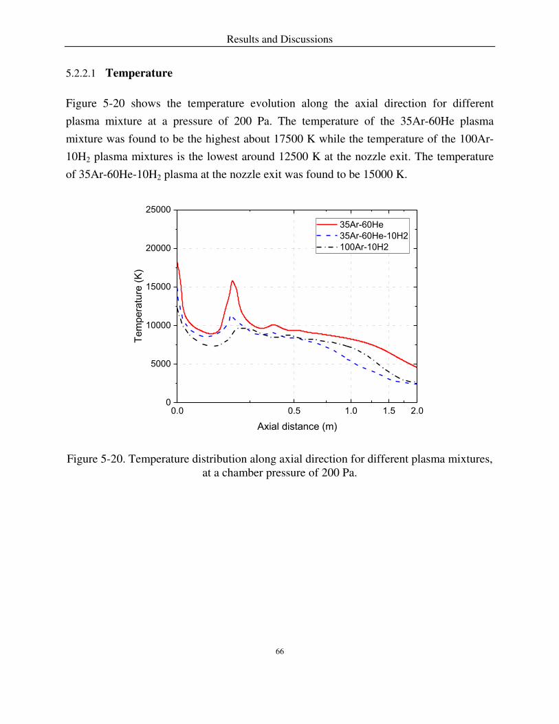
Results and Discussions
66
Temperature 5.2.2.1
Figure 5-20 shows the temperature evolution along the axial direction for different
plasma mixture at a pressure of 200 Pa. The temperature of the 35Ar-60He plasma
mixture was found to be the highest about 17500 K while the temperature of the 100Ar-
10H2 plasma mixtures is the lowest around 12500 K at the nozzle exit. The temperature
of 35Ar-60He-10H2 plasma at the nozzle exit was found to be 15000 K.
Figure 5-20. Temperature distribution along axial direction for different plasma mixtures, at a chamber pressure of 200 Pa.
0.0 0.5 1.0 1.5 2.00
5000
10000
15000
20000
25000
35Ar-60He
35Ar-60He-10H2
100Ar-10H2
Tem
pera
ture
(K
)
Axial distance (m)

Results and Discussions
67
Figure 5-21. Temperature profile along the radial direction for different plasma gases mixture at a stand-off distance of 1m at a chamber pressure of 200 Pa.
Figure 5-21 shows the temperature profile along the radial direction for different plasma
mixture at a stand-off distance of 1 m at a chamber pressure of 200 Pa. The width of the
plasma jet is around 0.4 m. The value of the temperature of 35Ar-60He plasma mixtures
shows a steady decline. The temperature falls slightly first and then maintains at the same
level for the 35Ar-60He-10H2 plasma mixture. In the case of 100Ar-10H2 plasma mixture,
the temperature suffers a gradual fall and levels off at 2500 K. Furthermore, the
temperature ended with a slight decrease for all plasma mixture. The width of the red
luminosity of 35Ar-60He-10H2 plasma mixture is larger than that of the 100Ar-10H2
plasma mixture in the plasma jet.
0.00 0.05 0.10 0.15 0.20 0.25 0.300
2000
4000
6000
8000
10000
Tem
pera
ture
(K
)
Radial distance (m)
35Ar-60He
35Ar-60He-10H2
100Ar-10H2
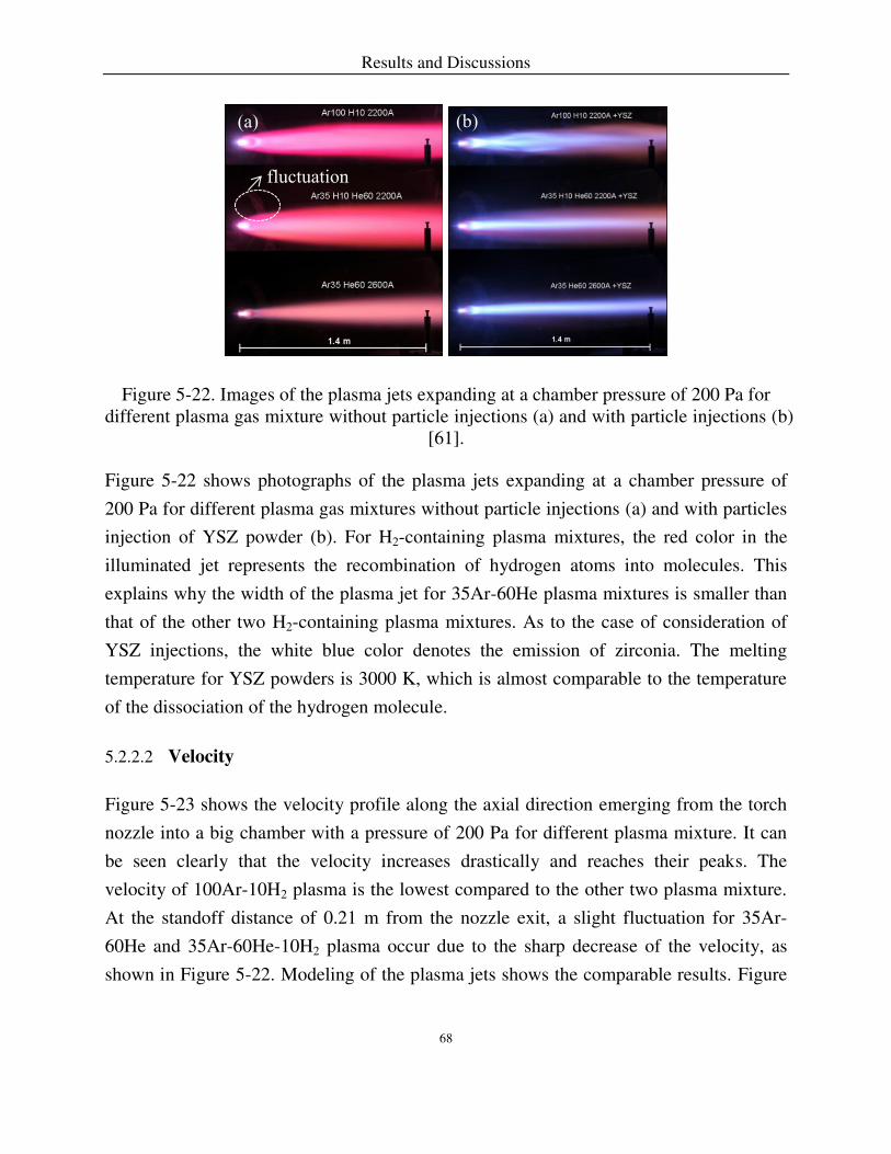
Results and Discussions
68
Figure 5-22. Images of the plasma jets expanding at a chamber pressure of 200 Pa for different plasma gas mixture without particle injections (a) and with particle injections (b)
[61].
Figure 5-22 shows photographs of the plasma jets expanding at a chamber pressure of
200 Pa for different plasma gas mixtures without particle injections (a) and with particles
injection of YSZ powder (b). For H2-containing plasma mixtures, the red color in the
illuminated jet represents the recombination of hydrogen atoms into molecules. This
explains why the width of the plasma jet for 35Ar-60He plasma mixtures is smaller than
that of the other two H2-containing plasma mixtures. As to the case of consideration of
YSZ injections, the white blue color denotes the emission of zirconia. The melting
temperature for YSZ powders is 3000 K, which is almost comparable to the temperature
of the dissociation of the hydrogen molecule.
Velocity 5.2.2.2
Figure 5-23 shows the velocity profile along the axial direction emerging from the torch
nozzle into a big chamber with a pressure of 200 Pa for different plasma mixture. It can
be seen clearly that the velocity increases drastically and reaches their peaks. The
velocity of 100Ar-10H2 plasma is the lowest compared to the other two plasma mixture.
At the standoff distance of 0.21 m from the nozzle exit, a slight fluctuation for 35Ar-
60He and 35Ar-60He-10H2 plasma occur due to the sharp decrease of the velocity, as
shown in Figure 5-22. Modeling of the plasma jets shows the comparable results. Figure
(a) (b)
fluctuation

Results and Discussions
69
5-24 presents the velocity profile along the radial direction at a standoff distance of 1 m.
The velocity of 35Ar-60He plasma jet is the highest.
Figure 5-23. Velocity profile along the axial direction for different plasma mixture at a chamber pressure of 200 Pa.
0.0 0.5 1.0 1.5 2.00
2000
4000
6000
8000
10000
12000V
elo
city (
m/s
)
Axial distance (m)
35Ar-60He
35Ar-60He-10H2
100Ar-10H2

Results and Discussions
70
Figure 5-24. Velocity profile along the radial direction for different plasma mixture at the standoff distance of 1m at a chamber pressure of 200 Pa.
Speed of Sound 5.2.2.3
Figure 5-25 shows the speed of sound profile along the axial direction for different
plasma mixture at a chamber pressure of 200 Pa. The speed of sound is proportional to
the square root of the product of the temperature and the ratio of specific heats. The
100Ar-10H2 plasma jet is the lowest due to the lowest temperature.
0.00 0.05 0.10 0.15 0.20 0.25 0.300
500
1000
1500
2000
2500
Ve
locity (
m/s
)
Radial distance (m)
35Ar-60He
35Ar-60He-10H2
100Ar-10H2

Results and Discussions
71
Figure 5-25. Sound speed profile along the axial direction for different plasma mixture at a chamber pressure of 200 Pa.
Mach number 5.2.2.4
Figure 5-26 and 5-27 show the Mach number profile along the axial and radial direction
for different plasma mixture at a chamber pressure of 200 Pa, respectively. At the Mach
numbers approaches 1, the flow is transonic. When the Mach number exceeds 1, the flow
is termed supersonic and contains shocks and expansion fans. The maximum value of the
Mach number reaches 4.5. At the standoff distance of 1m, the plasma jet is around
transonic.
0.0 0.5 1.0 1.5 2.01000
1500
2000
2500
3000
3500
4000
So
un
d s
pe
ed (
m/s
)
Axial distance (m)
35Ar-60He
35Ar-60He-10H2
100Ar-10H2

Results and Discussions
72
Figure 5-26. Mach number profile along the axial direction for different plasma mixture at a chamber pressure of 200 Pa.
Figure 5-27. Mach number profile along the radial direction for different plasma mixture at the standoff distance of 1m at a chamber pressure of 200 Pa.
0.0 0.5 1.0 1.5 2.0
0
1
2
3
4
5
Ma
ch
nu
mb
er
Axial distance (m)
35Ar-60He
35Ar-60He-10H2
100Ar-10H2
0.00 0.05 0.10 0.15 0.20 0.25 0.300.0
0.2
0.4
0.6
0.8
1.0
1.2
Ma
ch
nu
mb
er
Radial distance (m)
35Ar-60He
35Ar-60He-10H2
100Ar-10H2

Results and Discussions
73
Effect of the Substrate in the Plasma Jet 5.2.2.5
Figure 5-28 and 5-29 present the velocity profile around the horizontally and vertically
oriented substrates at a standoff distance of 1 m for the 35Ar-60He plasma, respectively.
The velocity close to the substrate can reach as large as 1500-2000 m/s for the vertically
oriented substrate. For the vertically oriented substrate, the velocity is homogenous; for
the horizontally oriented substrate, a big gradient of velocity exists around the substrate
surface.
Figure 5-28. Velocity profile around the horizontally oriented substrate at a standoff distance of 1 m for the 35Ar-60He plasma.
100 mm
Velo
city (
m/s
)
4.0x10³
3.5x10³
3.0x10³
2.5x10³
2.0x10³
1.5x10³
1.0x10³
5.0x10²
0.0

Results and Discussions
74
Figure 5-29. Velocity profile around the vertically oriented substrate at a standoff distance of 1 m for the 35Ar-60He plasma.
Figure 5-30 and 5-31 describe the temperature profile around the horizontal and vertical
substrate at a standoff distance of 1 m for the 35Ar-60He plasma, respectively. The
temperature of the substrate surface reaches up to 9000 K. For the horizontally oriented
substrate, the thickness of the boundary layer is proportional to the square root of the
distance from the leading edge of the substrate. It can be concluded that a greater
difference of temperature and velocity between the leading edge and bottom edge of the
substrate surface leads to distinct deposition process at the surface of the horizontally
oriented substrate.
Velo
city (
m/s
)
4.0x10³
3.5x10³
3.0x10³
2.5x10³
2.0x10³
1.5x10³
1.0x10³
5.0x10²
0.0
100 mm

Results and Discussions
75
Figure 5-30. Temperature profile around the horizontally oriented substrate at a standoff distance of 1 m for the 35Ar-60He plasma.
Figure 5-31. Temperature profile around the vertically oriented substrate at a standoff distance of 1 m for the 35Ar-60He plasma.
Tem
pera
ture
(K
)
1.0x10⁴
9.0x10³
8.0x10³
7.0x10³
6.0x10³
5.0x10³
4.0x10³
3.0x10³
2.0x10³
1.0x10³
100 mm
Te
mp
era
ture
(K
)
1.0x10⁴
9.0x10³
8.0x10³
7.0x10³
6.0x10³
5.0x10³
4.0x10³
3.0x10³
2.0x10³
1.0x10³
100 mm

Results and Discussions
76
Non-Line-of-Sight Depositions 5.2.2.6
The flow field behavior, as characterized by the velocity vector surrounding the substrate
scaled by pressure, is shown in Figure 5-32. The vapor flux changes its impingement
direction towards the substrate inside the boundary layer. The most significant deviations
from the normal happen at locations near the edges of the substrate. In reality, the
variability of the incident angle could also be associated with fluctuations or instability of
the flow field around the substrate as a result of the surface roughness. As a result, the
consideration of incident vapor angle at a normal distribution is practical in the Chapter
5.3 to simulate the built-up of columns. Even though the region of the highest deposition
rate is within the line of sight of the vapor source, it is possible to deposit coatings in
shadowed areas such as in the backside of the substrate. This non-line-of-sight deposition
can be validated in the experiment [5]. In the PS-PVD process, the feedstock particles are
injected to the plasma gun where it vaporizes and is transported in a laminar supersonic
plasma gas stream. Temperature is high enough to ensure vapor or small clusters that can
follow the gas flow. Eddies behind the sample lead to impingement of gases of the jet
onto the back surface of the sample.

Results and Discussions
77
Figure 5-32. Velocity vector field around the substrate color-scaled by the pressure. The substrate is vertical to the center of PS-PVD for 35Ar-60He plasma at a chamber pressure
of 200 Pa.
Optical Emission Evaluation 5.2.2.7
Optical emission spectroscopy is used to investigate 35Ar-60He plasma jet at a chamber
pressure of 200 Pa. The composition and spectral line intensities are calculated
considering non-equilibrium [179]. From the analysis of electrons concentrations of
Chapter 5.1, in the temperature ranging from 6000 K to 9000 K, electron densities in the
range of 1018-1020 m-3, the probability of non-equilibrium exists, in contrast, the electron
densities are over 1022 m-3 where a local thermodynamic equilibrium exists [180, 181].
These results give us the reasons why we have to analyze the plasma jet compositions out
of equilibrium. According to the calculation of the plasma composition, at the
400
300
200
100
0
Pre
ssu
re (
Pa
)

Results and Discussions
78
temperature ranging from 4,000 K to 10,000 K, it is not necessarily to consider the
ionization of helium.
The plasma jet temperature can be characterized by OES (typically from 8000 K < T <
14000 K ) [37]. The thermal plasma spraying process out of equilibrium has been
calculated in the literatures [17, 182, 183]. For a very low chamber pressure of 200 Pa,
the plasma jet seems to be out of thermal equilibrium because of insufficient transfer of
energy between the electrons and heavy species [184]. The challenge is to evaluate the
degree of non-equilibrium. Plasma compositions and spectral line intensities for 35Ar-
60He plasma are calculated according to the expressions in Chapter 3.2 and 3.3.
An overview of the radial spectrum is shown in Figure 5-33 that is measured by peer
PHD candidate W. He, which gives the emission spectrum of a 35Ar-60He plasma jet at
an axial stand-off distance of 1 m. The presence of intensive emission lines allows us to
analyze the argon ionization. As no helium ions intensities were detected a negligible
ionization of helium is assumed. The most intensive emission lines for Ar I are 696.5 nm,
751.5 nm, 763.5 nm and 772.4 nm, for He I are 447.2 nm, 587.6 nm and 667.8 nm,
respectively.

Results and Discussions
79
Figure 5-33. Emission spectrum of a 35Ar-60He plasma jet at an axial stand-off distance of 1 m.
Figure 5-34 depicts the dependence of two relative integrated spectral line intensities of
atoms and ions as a function of the radial direction at an axial stand-off distance of 1 m.
The normalized intensities as a function of the radial distance are shown in Figure 5-35.
The maximum values of spectral line intensities of Ar I 763.5 nm is located at a radial
distance of around 40 mm due to a big drop of argon atoms concentration. For the
intensities of Ar II 487.9 nm, the maximum locates in the center of the plasma jet. Argon
ions start to emit considerately at a temperature of around 6,000 K [185]. Furthermore,
the intensities of Ar I 763.5 nm are two orders magnitude higher than the intensities of Ar
II 487.9 nm.
0.00E+00
5.00E+04
1.00E+05
1.50E+05
2.00E+05
2.50E+05
300.00 400.00 500.00 600.00 700.00 800.00
He I 447.2
He I 587.6
He I 667.8
Ar I 763.5
Wavelength (nm)
Inte
nsi
ty (
cou
nts
)

Results and Discussions
80
Figure 5-34. Measured dependence of the relative integrated spectral line intensities of Ar I atoms and Ar II ions as a function of the radial direction, at an axial direction stand-off
distance of 1 m, compared to [186].
Figure 5-35. Measured dependence of the normalized intensities of Ar I atoms and Ar II ions as a function of the radial direction, at an axial direction stand-off distance of 1 m.
0 20 40 60 80 100100
101
102
103
104
105
106
107
Ar I 763.5 nm
Ar II 487.9 nm
Inte
nsity (
Co
un
ts)
Radial distance (mm)
0 20 40 60 80 100
0.0
0.2
0.4
0.6
0.8
1.0
Norm
aliz
ed Inte
nsity
Radial distance (mm)
Ar I 763.5 nm
Ar II 487.9 nm

Results and Discussions
81
Figure 5-36 shows the simulated results of temperature profile of a 35Ar-60He plasma jet
at a pressure of 200 Pa along a radial direction at an axial stand-off distance of 1 m at
equilibrium. Under these conditions, the temperature is slightly above 8,000 K in the
center of the plasma jet. The temperature decreases with increasing radial distance. As
shown in [164, 167], departures from equilibrium dominate at low temperature (~ 5,000
K). Therefore, the probability of non-equilibrium is higher in the fringe of the jet
compared to the center of the jet. Figure 5-37 presents the concentrations of atoms and
ions along the radial direction at an axial standoff distance of 1 m at equilibrium
corresponding to the temperature profile in Figure 5-36.
Figure 5-36. Simulated results of temperature profile of a 35Ar-60He plasma jet at a pressure of 200 Pa at an axial stand-off distance of 1 m at equilibrium.
0 50 100 150 200 250 3000
1000
2000
3000
4000
5000
6000
7000
8000
9000
Tem
pera
ture
(K
)
Radial distance (mm)
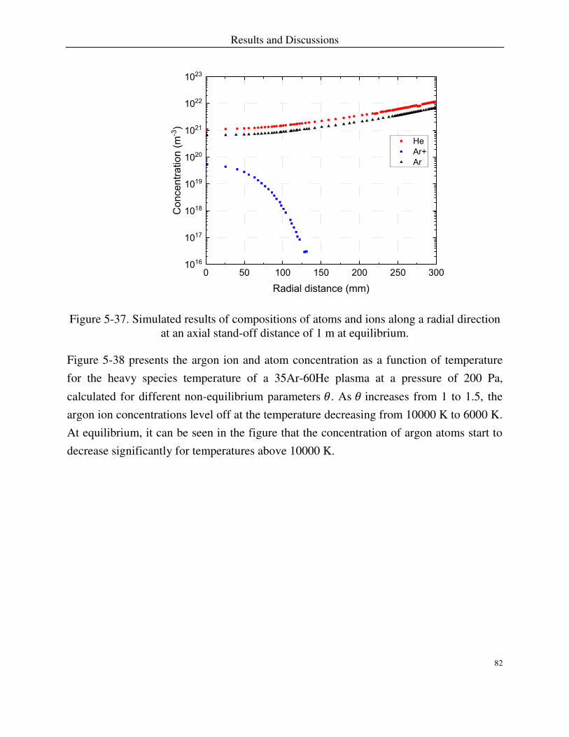
Results and Discussions
82
Figure 5-37. Simulated results of compositions of atoms and ions along a radial direction at an axial stand-off distance of 1 m at equilibrium.
Figure 5-38 presents the argon ion and atom concentration as a function of temperature
for the heavy species temperature of a 35Ar-60He plasma at a pressure of 200 Pa,
calculated for different non-equilibrium parameters 𝜃. As 𝜃 increases from 1 to 1.5, the
argon ion concentrations level off at the temperature decreasing from 10000 K to 6000 K.
At equilibrium, it can be seen in the figure that the concentration of argon atoms start to
decrease significantly for temperatures above 10000 K.
0 50 100 150 200 250 3001016
1017
1018
1019
1020
1021
1022
1023
He
Ar+
Ar
Concentr
ation (
m-3
)
Radial distance (mm)

Results and Discussions
83
Figure 5-38. Simulated dependence of the argon ions and atoms concentrations for the heavy species temperature of a 35Ar-60He plasma at a pressure of 200 Pa, calculated for
different non-equilibrium parameters 𝜃.
Figure 5-39 and 5-40 demonstrate the dependence of Ar I 763.5 nm and Ar II 487.9 nm
intensities as a function of the heavy species temperature of a 35Ar-60He plasma at a
pressure of 200 Pa, calculated for different non-equilibrium parameters 𝜃. At equilibrium,
maximum intensity of Ar I 763.5 nm is located at the center of the plasma jet. As shown
in Figure 5-40, the spectral line intensity of Ar II 487.9 nm at equilibrium is calculated
around 10-4 W/m3, which is is not high enough to be detected. Comparisons between the
peak of plots in Figure 5-35 and 5-39, it can be concluded that the non-equilibrium
parameter was found to be around 1.3.
0 2000 4000 6000 8000 10000 120001016
1017
1018
1019
1020
1021
1022
1023
non-equilibrium C
oncentr
ation (
m-3
)
Temperature (K)
Ar (=1)
Ar+(=1)
Ar(=1.4)
Ar+(=1.4)
Ar(=1.5)
Ar+(=1.5)

Results and Discussions
84
Figure 5-39. Simulated dependence of Ar I 763.5 nm normalized intensities as a function of radial distance of a 35Ar-60He plasma at a pressure of 200 Pa, calculated for different
non-equilibrium parameters 𝜃, at an axial stand-off distance of 1 m.
Figure 5-40. Simulated dependence of Ar II 487.9 nm intensities as a function of radial distance of a 35Ar-60He plasma at a pressure of 200 Pa, calculated for different non-
equilibrium parameters 𝜃, at an axial stand-off distance of 1 m.
0 20 40 60 80 100 120 140
0.0
0.2
0.4
0.6
0.8
1.0
Norm
aliz
ed Inte
nsity
Radial distance (m)
=1
=1.4
=1.5
non-equilibrium
Ar I 763.5 nm
0 20 40 60 80 100 120 14010-6
10-5
10-4
10-3
10-2
10-1
100
101
102
103
Ar I 487.9 nm
non-equilibrium
=1
=1.4
=1.5
Inte
nsity (
W m
-3)
Radial distance (m)

Results and Discussions
85
5.3 Monte Carlo Simulation of Plasma Spray-Physical Vapor
Deposition
Characteristics of columnar microstructures formation produced by the PS-PVD process
have been discussed in the before chapters. Monte Carlo simulation is applied to model
the column growth in the process, which is based on the following three main points: the
fast deposition rate, no consideration of the preferential crystal orientation of columns,
and the neglected surface and bulk diffusion.
5.3.1 Influence of Limited Diffusion
Figure 5-41 shows the influence of limited diffusion on the microstructure evolution.
Limited diffusion means when the newly incoming particle firstly makes contact with the
already deposited particles, but it is allowed to relax to the nearest free neighbor position.
After this relaxation process is completed, the next incident particle is introduced. Where
limited diffusion is considered, as shown in Figure 5-41(b), the microstructure has a
higher intra-columnar porosity (17%) compared to that of Figure 5-41(a). However, its
influence on inter-columnar porosity is negligible. In contrast to PS-PVD coatings shown
in Figure 2-17(b), it can be concluded that the consideration of limited diffusion gives
results that are more realistic.

Results and Discussions
86
Figure 5-41. Vapor flux distribution (μ, σ) = (0°, 30°), (a) without limited diffusion, (b) with limited diffusion, and (c) porosity comparison of (a) and (b).
5.3.2 Morphology of Simulated Columns
Deposition of Normal Vapor Incidence 5.3.2.1
Figure 5-42 shows four simulated column growths under normal vapor incidence (𝝁 =0°)
with standard deviations 𝝈 corresponding to 10°, 30°, 60°, and 90°, respectively. The
different colors (pixels) represent columns originating from different parental seeds. The
columns are not perfectly straight. When their height is still small, the difference in
0
0.1
0.2
0.3
0.4
0.5
without limited diffusion limited diffusion
Po
rosi
ty
a

Results and Discussions
87
column heights is not large enough to allow blocking of columns, then, the width of the
column is also still small, indicating that horizontal growth was limited. As the height
increases, the width of the column increases over a broad transition region until the width
of column is almost linearly growing with the height. This is due to competitive growth
(the width can only increase if other columns stop to grow) [137].
Figure 5-42. Simulated structures deposited under normal vapor incidence, 𝝁 =0°, steps = 3, (a) 𝝈 =10°, (b) 𝝈 =30°, (c) 𝝈 =60°, (d) 𝝈 =90°.
These graphs show that uniformity of the columns is significantly more pronounced for
narrow angle distributions. Furthermore, a broad distribution of incident vapor angle
results in an increased inter-columnar porosity. Under these conditions, the inter-
columnar gaps are wide, and competitive growth between neighboring is evident.
d
a

Results and Discussions
88
However, as the incident vapor is orientated parallel to the substrate surface normal, the
more deposited structure becomes densely packed. As standard deviation angle (σ) increases from 30° to 60° microstructures can grow from clearly columnar to loosely
symmetric cauliflower-shaped structures.
Deposition of Oblique Vapor Incidence 5.3.2.2
Figure 5-43 shows the influence of the value of mean angle 𝝁 of the vapor flux on the
simulated structures. The columnar structure therefore becomes increasingly more
noticeable with larger mean angles of vapor incidence. As the mean angle increases, the
uniformity of column’s size decreases. The most uniformly separated columnar structure
is seen in Figure 5-42(b) and Figure 5-43(a), which is the result of a narrowly distributed
vapor flux.
Since the incident direction was inclined, the resulting columns are also inclined. Just
above the substrate, the columns grow almost perpendicularly irrespective of incident
angle of the vapor flux. As the distance from the substrate increases, the columns become
gradually more inclined. It can be concluded that when the incident vapor angle is too
high (including mean angle and standard deviation angle), the changes of morphology,
porosity, orientation of columns are disregarded.
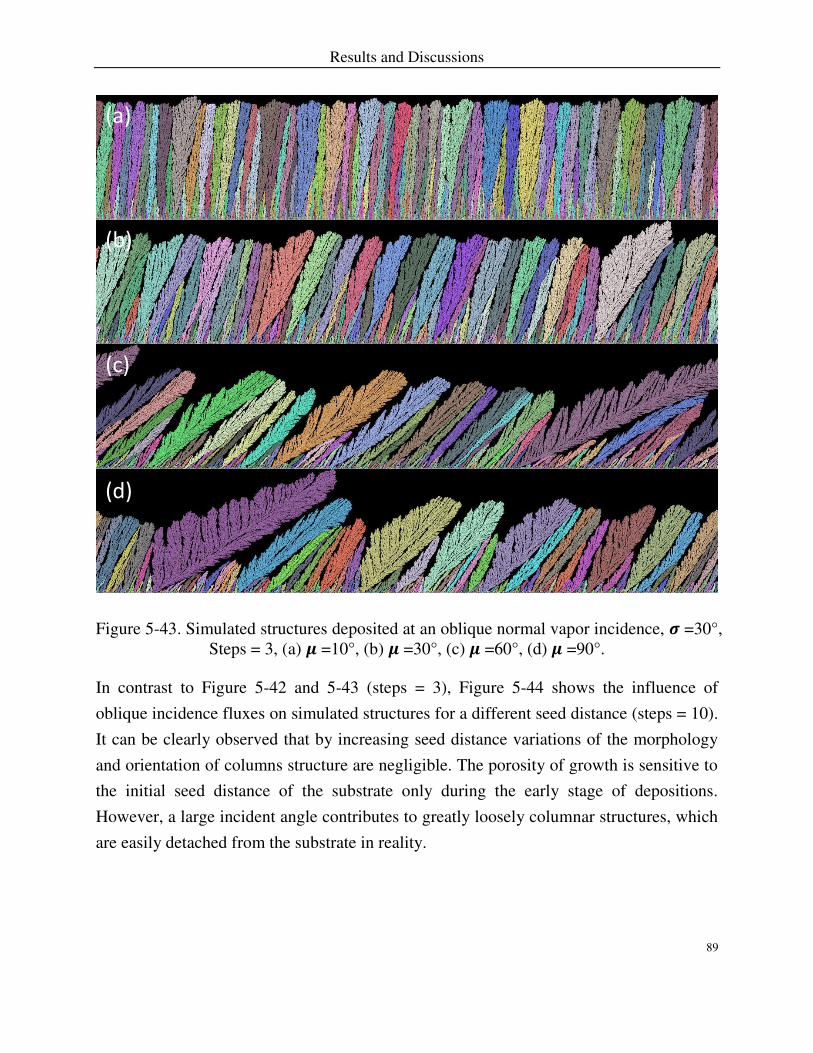
Results and Discussions
89
Figure 5-43. Simulated structures deposited at an oblique normal vapor incidence, 𝝈 =30°, Steps = 3, (a) 𝝁 =10°, (b) 𝝁 =30°, (c) 𝝁 =60°, (d) 𝝁 =90°.
In contrast to Figure 5-42 and 5-43 (steps = 3), Figure 5-44 shows the influence of
oblique incidence fluxes on simulated structures for a different seed distance (steps = 10).
It can be clearly observed that by increasing seed distance variations of the morphology
and orientation of columns structure are negligible. The porosity of growth is sensitive to
the initial seed distance of the substrate only during the early stage of depositions.
However, a large incident angle contributes to greatly loosely columnar structures, which
are easily detached from the substrate in reality.
d
a

Results and Discussions
90
Figure 5-44. Simulated structures deposited at an oblique normal vapor incidence, steps = 10, 𝝁 =60°, (a) 𝝈 =10°, (b) 𝝈 =30°, (c) 𝝈 =60°, (d) 𝝈 =90°.
According to [146], tapered columns with domed tops and columns separated by voids
result from self-shadowing where surface diffusion is not considered. A. Hospach [123]
presents PS-PVD coatings with big gaps between columns which is comparable with the
simulated columns.
Single Column Growth 5.3.2.3
Figure 5-45 presents the mechanism of a single column growth resulting from an
increased lateral component of the incoming vapor. Graphs of three columns indicate that
a
d

Results and Discussions
91
the feathery structures at the side of the column is formed. Without influence of another
column, higher flutuations of the incident vapor angle lead to wider columns.
Figure 5-45. One column growth at different distributions, (a) 𝝁, 𝝈 = (0°, 5°), (b) 𝝁, 𝝈 = (0°, 10°), (c) 𝝁, 𝝈 = (0°, 20°).
5.3.3 Porosity Analysis
The pore structure includes inter-columnar voids surrounding ~10 μm diameter width of columns and nanoscale pores exist within the columns [136, 187]. In addition to the inter-
columnar gaps, TBCs produced by PS-PVD process contain substantial amounts of intra-
columnar porosity. The large inter-columar pores reduce coating strain energy by
accommodating mismatches in thermal expansion, the microscale pores provide a
significant decrease in coating thermal conductivity in the heat flux progagation direction.
Nanoscale pores also decrease coating conductivity by increasing phonon scattering, but
are fast removed by sintering during operation of the engine [115, 188, 189]. Internal
pores (voids) or microcracks aligned perperdiculat to the direction of heat conduction,
which provides good thermal insulation [136, 143, 147]. In the boundary of columns,
porosity is typically arranged in a “feathery” morphology, comprising thin ribbon-like
pores at an angle to the column axis.
a

Results and Discussions
92
Figure 5-46. Porosity of simulated structures as a function of the different incident vapor angle (𝝁, 𝝈), steps = 3.
Figure 5-47. The porosity of simulated structures as a function of seeding and different incident vapor angle (𝝁, 𝝈).
Figure 5-46 shows the influence of the standard deviations 𝝈 on the porosity of the simulated columns. The results indicate that the porosity decreases when the vapor flux becomes more narrowly distributed. When the mean angle (𝜇 of the incident vapor angle increases the porosity increases. For very large mean angle and standard deviations, the
broadness of the distribution of incoming vapor results in a very large lateral component
0
0.1
0.2
0.3
0.4
0.5
μ=0° μ=30° μ=60°
σ= °
σ=3 °
σ= °
μ (degree)
Po
rosity
0
0.1
0.2
0.3
0.4
0.5
(0°,10°) (0°,60°) (30°,10°) (30°,60°)
steps=3
steps=10
vapor distribution (μ, σ)
Po
rosi
ty

Results and Discussions
93
of the growth. Figure 5-47 indicates that the effects of the seeding size on the porosity can be neglected.
Typical porosity of TBCs obtained by PS-PVD are about 10-30% , which is slightly
smaller that the porosity in simulated results. Two factors account for the discrepancy.
Firstly, TBCs produced by PS-PVD contain substantial amounts of intra-columnar
porosity. These tiny pores are simply neglected depending on the experimental anlysis
method and the morphology of the coatings. The second factor relates to the diffusion in
the boundary layer of the substrate at a very high substrate temperature and the influence
of surface roughness on the vapor flux direction.
5.3.4 Orientation of Columns
Figure 5-48 shows the relationship of the orientation of columns and the vapor incidence
angle. The orientation of the columns is smaller than the vapor incidence angle. The
inclination angle of the columns ( ) can often be well fitted with an vapor incident mean
angle (𝜇)
𝜇 = ∗ ( 5.1 )
when the self-shadowing effect from other columns is removed, as shown in Figure 5-45,
one column would grow exactly along the direction of the vapor flux. The orientation
angle is half the value of the vapor incidence angle. The error of the column orientation
angle is ± 1°. At higher mean angles, broader distribution of incoming vapor leads to
smaller titled angle of the columns owing to a higher probability of the lateral growth.

Results and Discussions
94
Figure 5-48. The influence of the vapor incidence angle on the orientation of columns.
Hodgkinson et al. [190] suggested the tangent rule by inserting a constant , for the
empirical observation, such that tan( )= tan( ). D. J. Srolovitz et al. claim that due to
self-shadowing the tangent rule is approximately valid, while diffusion reduces the
inclination angle of the column [191]. The columnar inclination angle ( ) with a vapor
incident angle ( ) can also be well fitted by tan( )= tan( ) [192, 193]. These equations
are not derived from any basic principles, but were found to corrolate well with the
predicted tendency of experimental results. In contrast to these publications, it can be
concluded that we also find a comparable expression.
In the future, in order to built up the relationship between the modeling of PS-PVD
process and the Monte Carlo simulation of the growth of the columns, the morphology
and surface roughness of columnar coatings is investigated. Columnar coatings produced
by PS-PVD process will be presented to compare the simulated microstrucutres by the
Monte Carlo model. Then, the surface roughness of deposited columnar coatings will be
combined with the plasma jet flow field around the substrate to evaluate the angle of the
impingement of the vapor flux onto the substrate. Finally, the relationship between the
incident vapor flux and the orientation of the columns can be evaluated from the
modeling and the experiment.
0
10
20
30
40
50
60
70
0 20 40 60 80 100
ori
en
tati
on
of
colu
mn
𝛽 , d
eg
ree
e (
°)
μ, degreee (°)
σ= °
σ=3 °
σ= °
σ=9 °

Results and Discussions
95
5.3.5 Microstructures of PS-PVD Coatings
Figure 5-49. SEM (back-scattered electron) images of columnar microstructures from W.He’s experiment, (a)-(b) 𝝁= 0°, in contrast to [194], (c)-(e) 𝝁= 90°.
Figure 5-49 shows the SEM images of columnar microstructures that are produced by
35Ar-60He plasma jet at a pressure of 200 Pa at a stand-off distance of 1 m in two
different conditions. The two top images (a)-(b) result from a vapor flux coming from the
substrate normal. Figure 5-49(a) shows the microstructure in the edge of the substrate,
and Figure 5-49(b) shows the microstructure located at the center of the substrate. In the
edge, the orientation of column is slightly tilted due to the change of the vapor flux vector.
The three bottom images (c)-(e) were obtained from a deposition with a horizontal
substrate. In the experiment, the morphology of columns is related to the substrate
temperature and the deposition rate. On one hand, the change morphology of the columns
is enhanced due to surface diffusion as it should be hotter at the edge, as shown in Figure
5-30. On the other hand, the deposition rate is smaller the further away from the leading
edge, so that columns are thinner shown in Figure 5-49 (c)-(e).
35°
d °
e °
μm μm μm
a
μm μm

Results and Discussions
96
The analysis of the orientation of the columns shows that the columns grow toward the
direction of the vapor flux. In contrast to Figure 5-48, Figure 5-49(c)-(e) shows the
predicted orientation angle is slightly bigger than the orientation angle in the experiment.
The titled angle of the columns decreases along the direction of the flow. Two reasons
explain the variation. The first is the presence of the boundary layer with varying
thickness. Especially in the case of the horizontal substrate, the boundary layer flow is
related with the distance to edge along the substrate surface, as shown in Figure 5-51.
Eddies will change the direction of the impingement of flow onto the substrate surface.
The second is the influence of surface roughness on the deposited coatings influence.
Figure 5-50. SEM (back-scattered electron) images of columnar microstructures [61], (a)-(b) 𝝁 > 0°.
Figure 5-50 produced by Hospach [61] presents an evident cauliflower microstructures
where the coatings are deposited on a titled substrate in a 35Ar-60He plasma jet at a
chamber pressure of 200 Pa at a stand-off distance of 1 m, which is comparable to Figure
5-43(a). As the substrate is tilted, the angle between the incident vapor flux and the
substrate surface increases, which leads to the growth of cauliflower-like columns.
5.3.6 Surface Morphology
Figure 5-51 illustrates the boundary layer around the substrate surface for the case of a
parallel deposition. When the plasma jet flows over the substrate surface, a velocity
boundary layer is developed over the surface due to fluid viscosity. Velocity boundary
layer thickness (𝜎 ) grows with the square root of distance from the leading edge of the
sample. For the hot plasma jet flows surround the substrate, the temperature boundary
layer is also formed around the substrate surface. The temperature boundary layer is the
200 µm100 µm 2 µm

Results and Discussions
97
region where the plasma jet temperature changes from its free-stream value to that at the
substrate surface. Heat transfer can take plasma from the plasma jet into the substrate
through the velocity boundary layer. For the ideal case, the temperature profile is the
same as the velocity profile through the entire boundary layer over the substrate surface.
For different positions at the substrate surface, the turbulence properties are distinct,
leading to different orientation of columns, as shown in Figure 5-49(c)-(e). In the laminar
boundary layer, the temperature profile gradually changes from the plasma jet value to
the surface as a parabolic shape, but in the turbulent boundary layer, the temperature
profile remains uniform and then suddenly changes to the surface value due to turbulent
mixing in the direction of back and forth or up and down. Therefore, along the
downstream of the plasma jet, the flow vector could change greatly.
To evaluate the surface roughness of columnar microstructures, samples with YSZ
coatings deposited by 35Ar-60He plasma jet at a standoff distance of 1 m at a chamber
pressure of 200 Pa were carried out on substrates with different orientation. Different
columnar microstructures were obtained; the results indicated that coatings on the vertical
sample may have lower roughness that that on the horizontal sample.
Figure 5-51. The boundary layer for the horizontal sample orientation.
Figure 5-52 shows three distinct roughness of the substrate surface before and after
coating deposited. Figure 5-52(a) depicts the graphite surface before the deposition. It is a
rather smooth with a roughness of maximum of 46.7 μm. For coatings deposited on the
vertical substrate, columns grow in the direction perpendicular to the substrate, the width
of resulting columns are smaller and the surface roughness of the coating is smoother
compared to that deposited on the horizontal sample (surface roughness of 82.8 μm vs
256.6 μm).
Substrate
Plasma jet

Results and Discussions
98
The orientation and width of columns is determined by the incident vapor flux.
According to the modeling of the built-up of columns in Chapter 5.3.2, broader oblique
vapor flux results in broader columns, and the resultant surface roughness is rougher,
which is comparable to the measurement shown in Figure 5-52(b) and 5-52(c).
Figure 5-52. The surface roughness of the substrate, (a) before the deposition with maximum values of 46.7 μm, (b) coating surface after deposition on the vertical substrate with maximum values of 82.8 μm, (c) coating surface after deposition on the horizontal
substrate with surface maximum values of 256.6 μm (center).
(a)
(b) (c)
200 um 200 um
200 um

Summary and Conclusions
99
6 Summary and Conclusions
This dissertation was focused on the modeling of the PS-PVD, as shown in Figure 6-1.
Five main topics were investigated: (1) thermodynamic and transport properties for
different plasma mixtures (35Ar-60He, 35Ar-60He-10H2, and 100Ar-10H2) depending on
the pressure and the temperature; (2) vacuum plasma spray; (3) plasma spray-physical
vapor deposition; (4) built-up of columnar coatings using the Monte-Carlo method; (5)
the validation by the experiment.
Figure 6-1. Images revealing the main topics in this work: (a) the plasma jet modeling, (b) the Monte Carlo simulation of the columns, (c) photograph of the plasma jet, (d)
columnar microstructures produced by PS-PVD process [61].
Studies on the photographs of plasma jets validated the plasma properties of the
simulated plasma spray with varying chamber pressures. Measurements of optical
emission spectroscopy highlighted the accuracy of the modeling of the temperature
distribution of plasma spray physical vapor deposition. Investigations on the influence of
the roughness of the substrate surface on the flow direction give further insight of the
built-up of columnar PS-PVD coatings. The conclusion of this work is that plasma jet
2.00x10² 1.06x10⁴ 2.10x10⁴
Temperature (K)
200 µm
(a)
(d)
(c)
(b)
1 m

Summary and Conclusions
100
simulation using the 2-D SST k-ω turbulence model, with the consideration of virtual
nozzle geometry but neglecting the arc dynamics in the torch, has the potential to result in
a reliable and precise investigation of the distribution of the temperature and turbulence
properties. The Monte-Carlo simulation, reflecting the fundamentals of the PS-PVD
process, reveals a promising and predictive method to simulate the microstructure of PS-
PVD columnar coatings. Detailed conclusions and remarks follow below.
In the first section, investigations of thermodynamics and transport suggest that 35Ar-
60He and 35Ar-60He-10H2 mixtures have a higher capacity to evaporate the feedstock
particles than 100Ar-10H2 in the PS-PVD process at a chamber pressure of 200 Pa, this is
experimentally validated by the microstructures produced by PS-PVD process [195]. The
recombination of hydrogen atoms at 2500 K plays an important role to increase the
enthalpy, specific heat capacity, and thermal conductivity of H2-containing plasma
mixtures to increase the substrate temperature.
In the second section, vacuum plasma spray was modeled at chamber pressures from 200
Pa to 10000 Pa of a 35Ar-60He plasma. The plasma jet is laminar and homogeneous for a
lower chamber pressure. Results of the simulation suggested that the length of the plasma
jet, the turbulence, the analysis of Mach disk, which were comparable to photographs of
the plasma jet. However, the two dimensional computational model cannot give a
comprehensive description of the jet turbulence, particularly, the formation of vortices.
The PS-PVD process at a chamber pressure of 200 Pa was modeled utilizing three types
of plasma mixtures (35Ar-60He, 35Ar-60He-10H2, and 100Ar-10H2). The jet using
35Ar-60He plasma yields the highest temperature of 18000 K while applying 100Ar-
10H2 plasma results in the lowest temperature of 12500 K at the nozzle outlet. At a stand-
off distance of 1 m from the exit of the nozzle, the temperature of a 35Ar-60He plasma
jet is the highest with 8000 K, while the temperature of a 35Ar-60He-10H2 plasma jet is
the lowest with 5000 K. The maximum velocity for 35Ar-60He and 35Ar-60He-10H2
plasma jets is roughly 10000 m/s, while for the 100Ar-10H2 jets the maximum velocity is
approximately 6000 m/s. At the standoff distance of 0.21 m from the nozzle exit,
fluctuations occur due to the sharp decrease of the velocity. Photographs of the plasma

Summary and Conclusions
101
jets show a comparable result. The velocity is about 2000 m/s at the standoff distance of
1 m for the three cases investigated.
The Saha ionization law was used to determine the distributions of plasma compositions
of PS-PVD processes at a chamber pressure of 200 Pa using 35Ar-60He mixtures.
Spectral line intensities were calculated utilizing the Boltzmann distribution depending
on the plasma composition and the temperature profile of the plasma jet modeling.
Intensities of Ar I 763.5 nm and Ar II 487.9 nm were estimated along the radial direction
at a stand-off distance of 1 m. It has shown that the parameter of the non-equilibrium
plays a role in determining the relative spectral line intensities. Results suggested that
intensities were not strong enough to be detected by OES at equilibrium. The non-
equilibrium parameter was estimated to be around 1.3.
Finally, a two-dimensional Monte Carlo simulation was employed to investigate the
formation of columnar growth in the physical vapor deposition process. Particularly, in
the case of the PS-PVD process, the surface diffusion in the coating can be neglected
because of the high deposition rate. As the incident angle of vapor flux changes from a
narrow to a broad fluctuation, the morphology of growth changes from a densely packed
structure to a clearly columnar structure, then to a cauliflower-like structure with large
gaps between the columns due to self-shadowing. Furthermore, the columns are oriented
towards to the direction of the vapor flux; the angle of columns equals almost half the
value of the angle of the incident vapor. As to the orientation and the morphology of the
columns, it can be concluded in the modeling of the built-up of columns that oblique
vapor flux results in broader columns and the resultant surface roughness is rougher,
which is comparable to the microstructures produced by a PS-PVD process. The results also indicate that the porosity increases when the vapor flux becomes broadly distributed. However, the influence of the initial seed distance on the porosity of structures proved to
be neglected.
However, in the future, since the composition is known, in the conditions of non-
equilibrium, thermodynamic and transport properties can also be calculated. Depending
on these properties, fluid dynamic simulation could also evaluate the temperature and the
turbulent properties of the plasma jet. When feedstock particles are injected, melted, and

Summary and Conclusions
102
evaporated, the melting processes and vapor distributions of feedstocks can be evaluated
in the plasma jet to analyze the plasma-particle interactions. Another possible topic is
when continuum flow breaks down at very low chamber pressure by intense and
numerous shocks, the rarefaction phenomenon lead to the transition from continuum flow
to slip flow and eventually to free molecular flow.
Furthermore, the surface roughness of coatings could be normalized and compared to the
surface of simulated columnar microstructures. Computational fluid dynamics will be
used to simulate the flow direction surrounding the substrate. So the orientation of titled
columns growth could be investigated by the influence of the surface roughness on the
flow direction. The influence of substrate temperature and the deposition rate on the
coating thickness and the detailed structural formation of coatings could be investigated
by this Monte Carlo method.

References
103
7 References
[1] D. Stöver, D. Hathiramani, R. Vaßen, and R. J. Damani, "Plasma-sprayed components for SOFC applications," Surface and Coatings Technology, vol. 201, pp. 2002-2005, 10/25/ 2006.
[2] R. Hui, Z. Wang, O. Kesler, L. Rose, J. Jankovic, S. Yick, et al., "Thermal plasma spraying for SOFCs: Applications, potential advantages, and challenges," Journal of Power
Sources, vol. 170, pp. 308-323, 7/10/ 2007.
[3] M. O. Jarligo, G. Mauer, M. Bram, S. Baumann, and R. Vaßen, "Plasma Spray Physical Vapor Deposition of La1−x Sr x Co y Fe1−y O3− Thin-Film Oxygen Transport Membrane on Porous Metallic Supports," Journal of Thermal Spray Technology, vol. 23, pp. 213-219, 2014.
[4] R. Vassen, A. Stuke, and D. Stöver, "Recent Developments in the Field of Thermal Barrier Coatings," Journal of Thermal Spray Technology, vol. 18, pp. 181-186, 2009.
[5] K. von Niessen and M. Gindrat, "Plasma Spray-PVD: A New Thermal Spray Process to Deposit Out of the Vapor Phase," Journal of Thermal Spray Technology, vol. 20, pp. 736-743, 2011.
[6] J. P. Trelles, E. Pfender, and J. V. R. Heberlein, "Modelling of the arc reattachment process in plasma torches," Journal of Physics D-Applied Physics, vol. 40, pp. 5635-5648, Sep 21 2007.
[7] P. C. Huang, J. Hebeylein, and E. Pfender, "A two-fluid model of turbulence for a thermal plasma jet," Plasma Chemistry and Plasma Processing, vol. 15, pp. 25-46, 1995.
[8] E. Pfender, "Plasma-Jet Behavior and Modeling Associated with the Plasma Spray Process," Thin Solid Films, vol. 238, pp. 228-241, Feb 1 1994.
[9] X. Chen, "The drag force on a spherical particle in a rarefied plasma flow with combined specular and diffuse reflection at the particle surface," Journal of Physics D: Applied Physics,
vol. 30, p. 2561, 1997.
[10] K. von Niessen and M. Gindrat, "Vapor phase deposition using a plasma spray process," Journal of Engineering for Gas Turbines and Power, vol. 133, p. 061301, 2011.
[11] P. Meakin, Fractals, scaling and growth far from equilibrium vol. 5: Cambridge university press, 1998.
[12] M. I. Boulos, P. Fauchais, and E. Pfender, Thermal plasmas: fundamentals and
applications: Springer Science & Business Media, 2013.

References
104
[13] P. L. Fauchais, J. V. R. Heberlein, and M. I. Boulos, "Fundamentals of Combustion and Thermal Plasma," in Thermal Spray Fundamentals: From Powder to Part, ed Boston, MA: Springer US, 2014, pp. 73-111.
[14] D. Merche, N. Vandencasteele, and F. Reniers, "Atmospheric plasmas for thin film deposition: A critical review," Thin Solid Films, vol. 520, pp. 4219-4236, 2012.
[15] C. M. Ferreira and M. Moisan, Microwave discharges: fundamentals and applications vol. 302: Springer Science & Business Media, 2013.
[16] J. Trelles, C. Chazelas, A. Vardelle, and J. Heberlein, "Arc plasma torch modeling," Journal of thermal spray technology, vol. 18, p. 728, 2009.
[17] J. P. Trelles, "Computational study of flow dynamics from a dc arc plasma jet," Journal
of Physics D: Applied Physics, vol. 46, p. 255201, 2013.
[18] M. Hrabovsky, V. Kopeckykopecky, V. Sember, T. Kavka, O. Chumak, and M. Konrad, "Properties of hybrid water/gas DC arc plasma torch," IEEE transactions on plasma science, vol. 34, pp. 1566-1575, 2006.
[19] E. Nogues, M. Vardelle, P. Fauchais, and P. Granger, "Arc voltage fluctuations: Comparison between two plasma torch types," Surface and Coatings Technology, vol. 202, pp. 4387-4393, 2008.
[20] P. Fauchais, G. Montavon, M. Vardelle, and J. Cedelle, "Developments in direct current plasma spraying," Surface and Coatings Technology, vol. 201, pp. 1908-1921, 2006.
[21] A. Lebouvier, C. Delalondre, F. Fresnet, F. Cauneau, and L. Fulcheri, "3D MHD modelling of low current–high voltage DC plasma torch under restrike mode," Journal of
Physics D: Applied Physics, vol. 45, p. 025204, 2011.
[22] R. Huang, H. Fukanuma, Y. Uesugi, and Y. Tanaka, "Comparisons of two models for the simulation of a DC arc plasma torch," Journal of thermal spray technology, vol. 22, pp. 183-191, 2013.
[23] M. Alaya, C. Chazelas, G. Mariaux, and A. Vardelle, "Arc-cathode coupling in the modeling of a conventional DC plasma spray torch," Journal of Thermal Spray Technology, vol. 24, pp. 3-10, 2015.
[24] V. Colombo, E. Ghedini, M. Boselli, P. Sanibondi, and A. Concetti, "3D static and time-dependent modelling of a dc transferred arc twin torch system," Journal of Physics D: Applied
Physics, vol. 44, p. 194005, 2011.

References
105
[25] E. Moreau, C. Chazelas, G. Mariaux, and A. Vardelle, "Modeling the restrike mode operation of a DC plasma spray torch," Journal of Thermal Spray Technology, vol. 15, pp. 524-530, 2006.
[26] V. Rat, P. André, J. Aubreton, M.-F. Elchinger, P. Fauchais, and A. Lefort, "Two-Temperature Transport Coefficients in Argon–Hydrogen Plasmas—II: Inelastic Processes and Influence of Composition," Plasma chemistry and plasma processing, vol. 22, pp. 475-493, 2002.
[27] V. Rat, P. André, J. Aubreton, M. F. Elchinger, P. Fauchais, and A. Lefort, "Two-Temperature Transport Coefficients in Argon–Hydrogen Plasmas—I: Elastic Processes and Collision Integrals," Plasma Chemistry and Plasma Processing, vol. 22, pp. 453-474, 2002.
[28] S. Janisson, E. Meillot, A. Vardelle, J. Coudert, B. Pateyron, and P. Fauchais, "Plasma spraying using Ar-He-H2 gas mixtures," Journal of thermal spray technology, vol. 8, pp. 545-552, 1999.
[29] B. Pateyron, M.-F. Elchinger, G. Delluc, and P. Fauchais, "Thermodynamic and transport properties of Ar-H2 and Ar-He plasma gases used for spraying at atmospheric pressure. I: Properties of the mixtures," Plasma chemistry and plasma processing, vol. 12, pp. 421-448, 1992.
[30] J. Aubreton, M. Elchinger, V. Rat, and P. Fauchais, "Two-temperature transport coefficients in argon–helium thermal plasmas," Journal of Physics D: Applied Physics, vol. 37, p. 34, 2003.
[31] A. Bobylev, "The Chapman-Enskog and Grad methods for solving the Boltzmann equation," in Akademiia Nauk SSSR Doklady, 1982, pp. 71-75.
[32] A. Murphy, "Transport coefficients of hydrogen and argon–hydrogen plasmas," Plasma
Chemistry and Plasma Processing, vol. 20, pp. 279-297, 2000.
[33] M. Van de Sanden, P. Schram, A. Peeters, J. Van der Mullen, and G. Kroesen, "Thermodynamic generalization of the Saha equation for a two-temperature plasma," Physical
Review A, vol. 40, p. 5273, 1989.
[34] V. Rat, P. André, J. Aubreton, M.-F. Elchinger, P. Fauchais, and A. Lefort, "Transport properties in a two-temperature plasma: theory and application," Physical Review E, vol. 64, p. 026409, 2001.
[35] C. Chazelas, J. Trelles, and A. Vardelle, "The Main Issues to Address in Modeling Plasma Spray Torch Operation," Journal of Thermal Spray Technology, vol. 26, pp. 3-11, 2017.
[36] P. Fauchais, J. Heberlein, and M. Boulos, "Thermal spray thermal spray fundamentals," ed: Springer, Berlin, 2014.

References
106
[37] P. Fauchais, "Understanding plasma spraying," Journal of Physics D: Applied Physics,
vol. 37, pp. R86-R108, 2004.
[38] A. H. Wilson, "Thermodynamics and statistical mechanics," Thermodynamics and
Statistical Mechanics, by AH Wilson, Cambridge, UK: Cambridge University Press, 1957, 1957.
[39] K. VanEvery, M. J. M. Krane, and R. W. Trice, "Parametric study of suspension plasma spray processing parameters on coating microstructures manufactured from nanoscale yttria-stabilized zirconia," Surface and Coatings Technology, vol. 206, pp. 2464-2473, 2012.
[40] R. Vaßen, H. Kaßner, G. Mauer, and D. Stöver, "Suspension Plasma Spraying: Process Characteristics and Applications," Journal of Thermal Spray Technology, vol. 19, pp. 219-225, January 01 2010.
[41] P. Fauchais, M. Vardelle, and S. Goutier, "Latest researches advances of plasma spraying: from splat to coating formation," Journal of Thermal Spray Technology, vol. 25, pp. 1534-1553, 2016.
[42] P. Fauchais, M. Fukumoto, A. Vardelle, and M. Vardelle, "Knowledge Concerning Splat Formation: An Invited Review," Journal of Thermal Spray Technology, vol. 13, pp. 337-360, 2004.
[43] A. McDonald, S. Chandra, M. Lamontagne, and C. Moreau, "Photographing impact of plasma-sprayed particles on metal substrates," Journal of thermal spray technology, vol. 15, pp. 708-716, 2006.
[44] A. Syed, A. Denoirjean, B. Hannoyer, P. Fauchais, P. Denoirjean, A. Khan, et al., "Influence of substrate surface conditions on the plasma sprayed ceramic and metallic particles flattening," Surface and Coatings Technology, vol. 200, pp. 2317-2331, 2005.
[45] H. Li, S. Costil, H.-L. Liao, C.-J. Li, M. Planche, and C. Coddet, "Effects of surface conditions on the flattening behavior of plasma sprayed Cu splats," Surface and Coatings
Technology, vol. 200, pp. 5435-5446, 2006.
[46] V. Pershin, M. Lufitha, S. Chandra, and J. Mostaghimi, "Effect of substrate temperature on adhesion strength of plasma-sprayed nickel coatings," Journal of Thermal Spray Technology,
vol. 12, pp. 370-376, 2003.
[47] R. S. Lima and B. R. Marple, "Thermal spray coatings engineered from nanostructured ceramic agglomerated powders for structural, thermal barrier and biomedical applications: a review," Journal of Thermal Spray Technology, vol. 16, pp. 40-63, 2007.
[48] P. Fauchais, G. Montavon, R. Lima, and B. Marple, "Engineering a new class of thermal spray nano-based microstructures from agglomerated nanostructured particles, suspensions and solutions: an invited review," Journal of Physics D: Applied Physics, vol. 44, p. 093001, 2011.

References
107
[49] O. Marchand, L. Girardot, M. Planche, P. Bertrand, Y. Bailly, and G. Bertrand, "An insight into suspension plasma spray: injection of the suspension and its interaction with the plasma flow," Journal of thermal spray technology, vol. 20, pp. 1310-1320, 2011.
[50] D. Chen, E. H. Jordan, and M. Gell, "Effect of solution concentration on splat formation and coating microstructure using the solution precursor plasma spray process," Surface and
Coatings Technology, vol. 202, pp. 2132-2138, 2008.
[51] E. Jordan, L. Xie, M. Gell, N. Padture, B. Cetegen, A. Ozturk, et al., "Superior thermal barrier coatings using solution precursor plasma spray," Journal of Thermal Spray Technology,
vol. 13, pp. 57-65, 2004.
[52] M. Planche, H. Liao, and C. Coddet, "Oxidation control in atmospheric plasma spraying coating," Surface and Coatings Technology, vol. 202, pp. 69-76, 2007.
[53] S. Brossard, P. Munroe, A. Tran, and M. Hyland, "Study of the splat formation for plasma sprayed NiCr on aluminum substrate as a function of substrate condition," Surface and
Coatings Technology, vol. 204, pp. 2647-2656, 2010.
[54] A. Tran and M. Hyland, "The role of substrate surface chemistry on splat formation during plasma spray deposition by experiments and simulations," Journal of thermal spray
technology, vol. 19, pp. 11-23, 2010.
[55] A. Tran, M. Hyland, K. Shinoda, and S. Sampath, "Inhibition of molten droplet deposition by substrate surface hydroxides," Surface and Coatings Technology, vol. 206, pp. 1283-1292, 2011.
[56] B. D. Kharas, G. Wei, S. Sampath, and H. Zhang, "Morphology and microstructure of thermal plasma sprayed silicon splats and coatings," Surface and Coatings Technology, vol. 201, pp. 1454-1463, 2006.
[57] S. Goutier, M. Vardelle, and P. Fauchais, "Understanding of spray coating adhesion through the formation of a single lamella," Journal of thermal spray technology, vol. 21, pp. 522-530, 2012.
[58] D. M. Mattox, Handbook of physical vapor deposition (PVD) processing: William Andrew, 2010.
[59] W. Kern, Thin film processes II vol. 2: Academic press, 2012.
[60] J. Singh and D. Wolfe, "Review Nano and macro-structured component fabrication by electron beam-physical vapor deposition (EB-PVD)," Journal of materials Science, vol. 40, pp. 1-26, 2005.

References
108
[61] A. Hospach, Untersuchung zum Thin Film Low Pressure Plasma Spraying (LPPS-TF)
Prozess: Forschungszentrum, Zentralbibliothek, 2012.
[62] A. Hospach, G. Mauer, R. Vaßen, and D. Stöver, "Characteristics of Ceramic Coatings Made by Thin Film Low Pressure Plasma Spraying (LPPS-TF)," Journal of Thermal Spray
Technology, vol. 21, pp. 435-440, 2012.
[63] M. Baeva, "A Survey of Chemical Nonequilibrium in Argon Arc Plasma," Plasma
Chemistry and Plasma Processing, pp. 1-18, 2016.
[64] C. Chazelas, J. P. Trelles, I. Choquet, and A. Vardelle, "Main Issues for a Fully Predictive Plasma Spray Torch Model and Numerical Considerations," Plasma chemistry and
plasma processing, vol. 37, pp. 627-651, 2017.
[65] L. Davidson, "Fluid mechanics, turbulent flow and turbulence modeling," Chalmers
University of Technology, Goteborg, Sweden (Nov 2011), 2011.
[66] C.-H. Moeng and P. P. Sullivan, "Large-eddy simulation," Encyclopedia of Atmospheric
Sciences, vol. 1140, p. 1150, 2002.
[67] N. Latifiyan, M. Farhadzadeh, P. Hanafizadeh, and M. H. Rahimian, "Numerical study of droplet evaporation in contact with hot porous surface using lattice Boltzmann method," International Communications in Heat and Mass Transfer, vol. 71, pp. 56-74, 2016.
[68] S. Chen and G. D. Doolen, "Lattice Boltzmann method for fluid flows," Annual review of
fluid mechanics, vol. 30, pp. 329-364, 1998.
[69] X. He and L.-S. Luo, "Theory of the lattice Boltzmann method: From the Boltzmann equation to the lattice Boltzmann equation," Physical Review E, vol. 56, p. 6811, 1997.
[70] H. Zhang, S. Hu, G. Wang, and J. Zhu, "Modeling and simulation of plasma jet by lattice Boltzmann method," Applied Mathematical Modelling, vol. 31, pp. 1124-1132, 2007.
[71] R. Djebeli, B. Pateyron, M. Elganaoui, and H. Sammouda, "Lattice Boltzmann Computation of Plasma Jet Behaviors: part II Argon-Nitrogen Mixture," arXiv preprint
arXiv:0911.5602, 2009.
[72] L. Zhang and M. L. Greenfield, "Relaxation time, diffusion, and viscosity analysis of model asphalt systems using molecular simulation," J Chem Phys, vol. 127, p. 194502, Nov 21 2007.
[73] R. Djebali, B. Pateyron, M. El Ganaoui, and H. Sammouda, "Axisymmetric high temperature jet behaviours based on a lattice Boltzmann computational method. Part I: Argon Plasma," 2008.

References
109
[74] H. Yu and K. Zhao, "Lattice Boltzmann method for compressible flows with high Mach numbers," Physical Review E, vol. 61, p. 3867, 2000.
[75] B. Selvan, K. Ramachandran, K. Sreekumar, T. Thiyagarajan, and P. Ananthapadmanabhan, "Numerical and experimental studies on DC plasma spray torch," Vacuum, vol. 84, pp. 444-452, 2009.
[76] K. Bobzin, M. Öte, J. Schein, S. Zimmermann, K. Möhwald, and C. Lummer, "Modelling the Plasma Jet in Multi-Arc Plasma Spraying," Journal of Thermal Spray Technology, vol. 25, pp. 1111-1126, 2016.
[77] W. Pan, X. Meng, G. Li, Q. Fei, and C. Wu, "Feasibility of laminar plasma-jet hardening of cast iron surface," Surface and Coatings Technology, vol. 197, pp. 345-350, 2005.
[78] W. Pan, W. Zhang, W. Ma, and C. Wu, "Characteristics of argon laminar DC plasma jet at atmospheric pressure," Plasma Chemistry and Plasma Processing, vol. 22, pp. 271-283, 2002.
[79] W. Pan, W. Zhang, W. Zhang, and C. Wu, "Generation of long, laminar plasma jets at atmospheric pressure and effects of flow turbulence," Plasma chemistry and plasma processing,
vol. 21, pp. 23-35, 2001.
[80] W. Pan, X. Meng, C. Wu, and X. Chen, "Experimental study on the thermal argon plasma generation and jet length change characteristics at atmospheric pressure," Plasma chemistry and
plasma processing, vol. 26, pp. 335-345, 2006.
[81] K. Cheng and X. Chen, "Effects of natural convection on the characteristics of long laminar argon plasma jets issuing upwards or downwards into ambient air—a numerical study," Journal of Physics D: Applied Physics, vol. 37, p. 2385, 2004.
[82] X. Chen, W. Pan, X. Meng, K. Cheng, D.-Y. Xu, and C. Wu, "What do we know about long laminar plasma jets?," Pure and Applied Chemistry, vol. 78, 2006.
[83] X.-J. Shao, Z.-S. Chang, H.-B. Mu, W.-L. Liao, and G.-J. Zhang, "Experimental and numerical investigation on the interaction between Ar flow channel and Ar plasma jet at atmospheric pressure," IEEE Transactions on plasma science, vol. 41, pp. 899-906, 2013.
[84] M. Xian, P. Wen-xia, Z. Wen-hong, and W. Cheng-kang, "Heat flux characterization of DC laminar-plasma jets impinging on a flat plate at atmospheric pressure," Plasma Science and
Technology, vol. 3, p. 953, 2001.
[85] H.-X. Wang, X. Chen, K. Cheng, and W. Pan, "Modeling study on the characteristics of laminar and turbulent argon plasma jets impinging normally upon a flat plate in ambient air," International journal of heat and mass transfer, vol. 50, pp. 734-745, 2007.

References
110
[86] D.-Y. Xu and X. Chen, "Effects of surrounding gas on the long laminar argon plasma jet characteristics," International Communications in Heat and Mass Transfer, vol. 32, pp. 939-946, 2005.
[87] H.-P. Li and X. Chen, "Three-dimensional modeling of the turbulent plasma jet impinging upon a flat plate and with transverse particle and carrier-gas injection," Plasma
chemistry and plasma processing, vol. 22, pp. 27-58, 2002.
[88] M. Vardelle, A. Vardelle, P. Fauchais, and M. Boulos, "Plasma—particle momentum and heat transfer: Modelling and measurements," AIChE Journal, vol. 29, pp. 236-243, 1983.
[89] M. Vardelle, A. Vardelle, A. Leger, P. Fauchais, and D. Gobin, "Influence of particle parameters at impact on splat formation and solidification in plasma spraying processes," Journal of Thermal Spray Technology, vol. 4, pp. 50-58, 1995.
[90] P. Buchner, H. Schubert, J. Uhlenbusch, and K. Willée, "Modeling and Spectroscopic Investigations on the Evaporation of Zirconia in a Thermal rf Plasma," Plasma chemistry and
plasma processing, vol. 19, pp. 341-362, 1999.
[91] H.-B. Xiong, L.-L. Zheng, L. Li, and A. Vaidya, "Melting and oxidation behavior of in-flight particles in plasma spray process," International Journal of Heat and Mass Transfer, vol. 48, pp. 5121-5133, 2005.
[92] Y. Bai, Z. Han, H. Li, C. Xu, Y. Xu, C. Ding, et al., "Structure–property differences between supersonic and conventional atmospheric plasma sprayed zirconia thermal barrier coatings," Surface and Coatings Technology, vol. 205, pp. 3833-3839, 2011.
[93] K. Bobzin, N. Bagcivan, D. Parkot, and I. Petković, "Simulation of PYSZ particle impact and solidification in atmospheric plasma spraying coating process," Surface and Coatings
Technology, vol. 204, pp. 1211-1215, 2010.
[94] P. Fauchais and A. Vardelle, "Innovative and emerging processes in plasma spraying: from micro-to nano-structured coatings," Journal of Physics D: Applied Physics, vol. 44, p. 194011, 2011.
[95] A.-F. Kanta, M.-P. Planche, G. Montavon, and C. Coddet, "In-flight and upon impact particle characteristics modelling in plasma spray process," Surface and Coatings Technology,
vol. 204, pp. 1542-1548, 2010.
[96] B. Selvan, K. Ramachandran, B. Pillai, and D. Subhakar, "Numerical modelling of Ar-N2 plasma jet impinging on a flat substrate," Journal of thermal spray technology, vol. 20, pp. 534-548, 2011.

References
111
[97] Y. Wang, J. Hua, Z. Liu, Y. Zeng, Y. Zhou, and H. Wang, "Melting index characterization and thermal conductivity model of plasma sprayed YSZ coatings," Journal of
the European Ceramic Society, vol. 32, pp. 3701-3707, 2012.
[98] K. Cheng and X. Chen, "Prediction of the entrainment of ambient air into a turbulent argon plasma jet using a turbulence-enhanced combined-diffusion-coefficient method," International journal of heat and mass transfer, vol. 47, pp. 5139-5148, 2004.
[99] G. Li, W. Pan, X. Meng, and C. Wu, "Application of similarity theory to the characterization of non-transferred laminar plasma jet generation," Plasma Sources Science and
Technology, vol. 14, p. 219, 2005.
[100] F. Qunbo, W. Lu, and W. Fuchi, "3D simulation of the plasma jet in thermal plasma spraying," Journal of Materials Processing Technology, vol. 166, pp. 224-229, 2005.
[101] H.-B. Xiong, L.-L. Zheng, S. Sampath, R. L. Williamson, and J. R. Fincke, "Three-dimensional simulation of plasma spray: effects of carrier gas flow and particle injection on plasma jet and entrained particle behavior," International Journal of Heat and Mass Transfer,
vol. 47, pp. 5189-5200, 2004.
[102] S. Shang, B. Guduri, M. Cybulsky, and R. Batra, "Effect of turbulence modulation on three-dimensional trajectories of powder particles in a plasma spray process," Journal of Physics
D: Applied Physics, vol. 47, p. 405206, 2014.
[103] P. Fauchais, A. Joulia, S. Goutier, C. Chazelas, M. Vardelle, A. Vardelle, et al., "Suspension and solution plasma spraying," Journal of Physics D: Applied Physics, vol. 46, p. 224015, 2013.
[104] K. Pourang, C. Moreau, and A. Dolatabadi, "Effect of Substrate and Its Shape on in-Flight Particle Characteristics in Suspension Plasma Spraying," Journal of Thermal Spray
Technology, vol. 25, pp. 44-54, 2015.
[105] A. Guignard, G. Mauer, R. Vaßen, and D. Stöver, "Deposition and characteristics of submicrometer-structured thermal barrier coatings by suspension plasma spraying," Journal of
thermal spray technology, vol. 21, pp. 416-424, 2012.
[106] A. Bacciochini, F. Ben-Ettouil, E. Brousse, J. Ilavsky, G. Montavon, A. Denoirjean, et al., "Quantification of void networks of as-sprayed and annealed nanostructured yttria-stabilized zirconia (YSZ) deposits manufactured by suspension plasma spraying," Surface and Coatings
Technology, vol. 205, pp. 683-689, 2010.
[107] P. Carpio, E. Rayón, L. Pawłowski, A. Cattini, R. Benavente, E. Bannier, et al., "Microstructure and indentation mechanical properties of YSZ nanostructured coatings obtained by suspension plasma spraying," Surface and Coatings Technology, vol. 220, pp. 237-243, 2013.

References
112
[108] K. VanEvery, M. J. Krane, R. W. Trice, H. Wang, W. Porter, M. Besser, et al., "Column formation in suspension plasma-sprayed coatings and resultant thermal properties," Journal of
thermal spray technology, vol. 20, pp. 817-828, 2011.
[109] G. Mauer, "Process diagnostics in suspension plasma spraying," Surface and Coatings
Technology, pp. 961–966, 2010.
[110] D. Waldbillig and O. Kesler, "Effect of suspension plasma spraying process parameters on YSZ coating microstructure and permeability," Surface and Coatings Technology, vol. 205, pp. 5483-5492, 2011.
[111] E. Meillot, R. Vert, C. Caruyer, D. Damiani, and M. Vardelle, "Manufacturing nanostructured YSZ coatings by suspension plasma spraying (SPS): effect of injection parameters," Journal of Physics D: Applied Physics, vol. 44, p. 194008, 2011.
[112] A. Ganvir, N. Curry, S. Björklund, N. Markocsan, and P. Nylén, "Characterization of microstructure and thermal properties of YSZ coatings obtained by axial suspension plasma spraying (ASPS)," Journal of Thermal Spray Technology, vol. 24, pp. 1195-1204, 2015.
[113] P. Fauchais and G. Montavon, "Latest developments in suspension and liquid precursor thermal spraying," Journal of Thermal Spray Technology, vol. 19, pp. 226-239, 2010.
[114] R. Christensen, D. Lipkin, D. R. Clarke, and K. Murphy, "Nondestructive evaluation of the oxidation stresses through thermal barrier coatings using Cr3+ piezospectroscopy," Applied
Physics Letters, vol. 69, pp. 3754-3756, 1996.
[115] D. R. Clarke, M. Oechsner, and N. P. Padture, "Thermal-barrier coatings for more efficient gas-turbine engines," MRS Bulletin, vol. 37, pp. 891-898, 2012.
[116] N. P. Padture, M. Gell, and E. H. Jordan, "Thermal barrier coatings for gas-turbine engine applications," Science, vol. 296, pp. 280-284, 2002.
[117] G. Mauer, R. Vaßen, and D. Stöver, "Thin and dense ceramic coatings by plasma spraying at very low pressure," Journal of thermal spray technology, vol. 19, pp. 495-501, 2010.
[118] C.-X. Li, C.-J. Li, and L.-J. Guo, "Effect of composition of NiO/YSZ anode on the polarization characteristics of SOFC fabricated by atmospheric plasma spraying," international
journal of hydrogen energy, vol. 35, pp. 2964-2969, 2010.
[119] M. O. Jarligo, G. Mauer, M. Bram, S. Baumann, and R. Vaßen, "Plasma Spray Physical Vapor Deposition of La1− xSrxCoyFe1− yO3− Thin-Film Oxygen Transport Membrane on Porous Metallic Supports," Journal of Thermal Spray Technology, vol. 23, pp. 213-219, 2014.
[120] X. Chen, S. Kuroda, T. Ohnuki, H. Araki, M. Watanabe, and Y. Sakka, "Effects of Processing Parameters on the Deposition of Yttria Partially Stabilized Zirconia Coating During
References
113
Suspension Plasma Spray," Journal of the American Ceramic Society, vol. 99, pp. 3546-3555, 2016.
[121] B. Bernard, A. Quet, L. Bianchi, A. Joulia, A. Malié, V. Schick, et al., "Thermal Insulation Properties of YSZ Coatings: Suspension Plasma Spraying (SPS) Versus Electron Beam Physical Vapor Deposition (EB-PVD) and Atmospheric Plasma Spraying (APS)," Surface
and Coatings Technology, 2016.
[122] A. F. Renteria, B. Saruhan, U. Schulz, H.-J. Raetzer-Scheibe, J. Haug, and A. Wiedenmann, "Effect of morphology on thermal conductivity of EB-PVD PYSZ TBCs," Surface
and Coatings Technology, vol. 201, pp. 2611-2620, 2006.
[123] A. Hospach, G. Mauer, R. Vaßen, and D. Stöver, "Columnar-Structured Thermal Barrier Coatings (TBCs) by Thin Film Low-Pressure Plasma Spraying (LPPS-TF)," Journal of Thermal
Spray Technology, vol. 20, pp. 116-120, 2010.
[124] R. Vaßen, M. O. Jarligo, T. Steinke, D. E. Mack, and D. Stöver, "Overview on advanced thermal barrier coatings," Surface and Coatings Technology, vol. 205, pp. 938-942, 2010.
[125] L. Gao, L. Wei, H. Guo, S. Gong, and H. Xu, "Deposition mechanisms of yttria-stabilized zirconia coatings during plasma spray physical vapor deposition," Ceramics
International, vol. 42, pp. 5530-5536, 2016.
[126] C. Li, H. Guo, L. Gao, L. Wei, S. Gong, and H. Xu, "Microstructures of yttria-stabilized zirconia coatings by plasma spray-physical vapor deposition," Journal of Thermal Spray
Technology, vol. 24, pp. 534-541, 2015.
[127] S. Rezanka, D. E. Mack, G. Mauer, D. Sebold, O. Guillon, and R. Vaßen, "Investigation of the resistance of open-column-structured PS-PVD TBCs to erosive and high-temperature corrosive attack," Surface and Coatings Technology, vol. 324, pp. 222-235, 2017.
[128] A. B. Murphy, "Formation of titanium nanoparticles from a titanium tetrachloride plasma," Journal of Physics D: Applied Physics, vol. 37, pp. 2841-2847, 2004.
[129] G. Mauer, A. Hospach, and R. Vaßen, "Process development and coating characteristics of plasma spray-PVD," Surface and Coatings Technology, vol. 220, pp. 219-224, 2013.
[130] G. Mauer, M. Jarligo, S. Rezanka, A. Hospach, and R. Vaßen, "Novel opportunities for thermal spray by PS-PVD," Surface and coatings technology, vol. 268, pp. 52-57, 2015.
[131] K. Von Niessen, M. Gindrat, and A. Refke, "Vapor phase deposition using plasma spray-PVD™," Journal of Thermal Spray Technology, vol. 19, pp. 502-509, 2010.
[132] A. Luque, J. Aldazabal, A. Martin-Meizoso, J. Martinez-Esnaola, J. G. Sevillano, and R. Farr, "Simulation of the microstructural evolution during liquid phase sintering using a

References
114
geometrical Monte Carlo model," Modelling and Simulation in Materials Science and
Engineering, vol. 13, p. 1057, 2005.
[133] A. Luque, J. Aldazabal, J. Martínez-Esnaola, A. Martín-Meizoso, J. G. Sevillano, and R. Farr, "Diffusional Monte Carlo model of liquid-phase sintering," Mathematics and Computers in
Simulation, vol. 81, pp. 2564-2580, 2011.
[134] Z. Wang, Y. Li, and J. B. Adams, "Kinetic lattice Monte Carlo simulation of facet growth rate," Surface science, vol. 450, pp. 51-63, 2000.
[135] D. Bellucci, V. Cannillo, and A. Sola, "Monte Carlo simulation of microstructure evolution in biphasic-systems," Ceramics International, vol. 36, pp. 1983-1988, 2010.
[136] T. M. Rodgers, H. Zhao, and H. N. Wadley, "Microstructure of vapor deposited coatings on curved substrates," Journal of Vacuum Science & Technology A: Vacuum, Surfaces, and
Films, vol. 33, p. 05E118, 2015.
[137] Y. G. Yang, D. D. Hass, and H. N. G. Wadley, "Porosity control in zig-zag vapor-deposited films," Thin Solid Films, vol. 471, pp. 1-11, 2005.
[138] Y. G. Yang, R. A. Johnson, and H. N. G. Wadley, "A Monte Carlo simulation of the physical vapor deposition of nickel," Acta Materialia, vol. 45, pp. 1455-1468, 4// 1997.
[139] C. Krill Iii and L.-Q. Chen, "Computer simulation of 3-D grain growth using a phase-field model," Acta materialia, vol. 50, pp. 3059-3075, 2002.
[140] H. Frey and H. R. Khan, Handbook of thin film technology: Springer, 2015.
[141] Ö. Altun and Y. Böke, "Effect of the microstructure of EB-PVD thermal barrier coatings on the thermal conductivity and the methods to reduce the thermal conductivity," Archives of
Materials Science, vol. 48, p. 48, 2009.
[142] M. Caliez, J.-L. Chaboche, F. Feyel, and S. Kruch, "Numerical simulation of EBPVD thermal barrier coatings spallation," Acta Materialia, vol. 51, pp. 1133-1141, 2003.
[143] M. Yoshiya, K. Wada, B. Jang, and H. Matsubara, "Computer simulation of nano-pore formation in EB-PVD thermal barrier coatings," Surface and Coatings Technology, vol. 187, pp. 399-407, 2004.
[144] S. Baek and V. Prabhu, "Simulation model for an EB-PVD coating structure using the level set method," Journal of Manufacturing Processes, vol. 11, pp. 1-7, 2009.
[145] R. Messier, "Revised structure zone model for thin film physical structure," Journal of
Vacuum Science & Technology A: Vacuum, Surfaces, and Films, vol. 2, p. 500, 1984.

References
115
[146] M. M. Hawkeye and M. J. Brett, "Glancing angle deposition: fabrication, properties, and applications of micro-and nanostructured thin films," Journal of Vacuum Science & Technology
A: Vacuum, Surfaces, and Films, vol. 25, pp. 1317-1335, 2007.
[147] U. Schulz, S. Terry, and C. Levi, "Microstructure and texture of EB-PVD TBCs grown under different rotation modes," Materials science and engineering: A, vol. 360, pp. 319-329, 2003.
[148] J. Cho, S. G. Terry, R. LeSar, and C. G. Levi, "A kinetic Monte Carlo simulation of film growth by physical vapor deposition on rotating substrates," Materials Science and Engineering:
A, vol. 391, pp. 390-401, 2005.
[149] H. Zhao, F. Yu, T. D. Bennett, and H. N. G. Wadley, "Morphology and thermal conductivity of yttria-stabilized zirconia coatings," Acta Materialia, vol. 54, pp. 5195-5207, 2006.
[150] U. Schulz and M. Schmücker, "Microstructure of ZrO2 thermal barrier coatings applied by EB-PVD," Materials Science and Engineering: A, vol. 276, pp. 1-8, 2000.
[151] J. A. Thornton, "High rate thick film growth," Annual review of materials science, vol. 7, pp. 239-260, 1977.
[152] B. Movchan and A. Demchishin, "STRUCTURE AND PROPERTIES OF THICK CONDENSATES OF NICKEL, TITANIUM, TUNGSTEN, ALUMINUM OXIDES, AND ZIRCONIUM DIOXIDE IN VACUUM," Fiz. Metal. Metalloved. 28: 653-60 (Oct 1969). 1969.
[153] S. Mukherjee and D. Gall, "Structure zone model for extreme shadowing conditions," Thin Solid Films, vol. 527, pp. 158-163, 2013.
[154] C. Park, S. Choi, J. Chae, S. Kim, H. Kim, and Y.-S. Oh, "Effect of Substrate Rotation on the Phase Evolution and Microstructure of 8YSZ Coatings Fabricated by EB-PVD," Journal of
the Korean Ceramic Society, vol. 53, pp. 81-86, 2016.
[155] F. R. Menter, "Two-equation eddy-viscosity turbulence models for engineering applications," AIAA journal, vol. 32, pp. 1598-1605, 1994.
[156] S. E. Rogers, D. Kwak, and J. L. Chang, "Numerical Solution Of Navier-Stokes Equations," 1989.
[157] D. Ivchenko, T. Zhang, G. Mariaux, A. Vardelle, S. Goutier, and T. E. Itina, "On the Validity of Continuum Computational Fluid Dynamics Approach Under Very Low-Pressure Plasma Spray Conditions," Journal of Thermal Spray Technology, pp. 1-11.
[158] B. J. McBride, S. Gordon, and M. A. Reno, "Coefficients for calculating thermodynamic and transport properties of individual species," 1993.

References
116
[159] G. Mauer, "Plasma Characteristics and Plasma-Feedstock Interaction Under PS-PVD Process Conditions," Plasma Chemistry and Plasma Processing, vol. 34, pp. 1171-1186, Sep 2014.
[160] G. Mauer and R. Vaßen, "Plasma Spray-PVD: Plasma Characteristics and Impact on Coating Properties," Journal of Physics: Conference Series, vol. 406, p. 012005, 2012.
[161] W. B. White, S. M. Johnson, and G. B. Dantzig, "Chemical equilibrium in complex mixtures," The Journal of Chemical Physics, vol. 28, pp. 751-755, 1958.
[162] P. André, "Partition functions and concentrations in plasmas out of thermal equilibrium," IEEE transactions on plasma science, vol. 23, pp. 453-458, 1995.
[163] P. André, M. Abbaoui, A. Lefort, and M. Parizet, "Numerical method and composition in multi-temperature plasmas: Application to an Ar-H 2 mixture," Plasma chemistry and plasma
processing, vol. 16, pp. 379-398, 1996.
[164] A. Gleizes, B. Chervy, and J. Gonzalez, "Calculation of a two-temperature plasma composition: bases and application to SF6," Journal of Physics D: Applied Physics, vol. 32, p. 2060, 1999.
[165] A. Potapov, "Chemical equilibrium of multitemperature systems," High Temp, vol. 4, p. 48, 1966.
[166] E. Richley and D. Tuma, "On the determination of particle concentrations in multitemperature plasmas," Journal of Applied Physics, vol. 53, pp. 8537-8542, 1982.
[167] P. André, J. Ondet, R. Pellet, and A. Lefort, "The calculation of monatomic spectral lines' intensities and composition in plasma out of thermal equilibrium; evaluation of thermal disequilibrium in ICP torches," Journal of Physics D: Applied Physics, vol. 30, p. 2043, 1997.
[168] D. Chen, K. Hsu, and E. Pfender, "Two-temperature modeling of an arc plasma reactor," Plasma Chemistry and Plasma Processing, vol. 1, pp. 295-314, 1981.
[169] A. Fridman, "Plasma-Chemical Kinetics, Thermodynamics, and Electrodynamics," in Plasma Chemistry:, ed Cambridge: Cambridge University Press, 2008, pp. 92-156.
[170] A. Kramida, Y. Ralchenko, and J. Reader, "NIST atomic spectra database (ver. 5.1)," National Institute of Standards and Technology, Gaithersburg, MD, 2013.
[171] S. Gordon and B. J. McBride, Computer program for calculation of complex chemical
equilibrium compositions and applications vol. 1: National Aeronautics and Space Administration, Office of Management, Scientific and Technical Information Program, 1994.

References
117
[172] F. J. Zeleznik and S. Gordon, "An analytical investigation of three general methods of calculating chemical-equilibrium compositions," 1960.
[173] R. S. Snedeker, "A study of free jet impingement. Part 1. Mean properties of free and impinging jets," Journal of fluid Mechanics, vol. 45, pp. 281-319, 1971.
[174] D. Munday, E. Gutmark, J. Liu, and K. Kailasanath, "Flow structure and acoustics of supersonic jets from conical convergent-divergent nozzles," Physics of Fluids (1994-present),
vol. 23, p. 116102, 2011.
[175] T. White and B. Milton, "Shock wave calibration of under-expanded natural gas fuel jets," Shock Waves, vol. 18, pp. 353-364, 2008.
[176] H.-A. Schreiber, W. Steinert, and B. Kusters, "Effects of Reynolds Number and Free-Stream Turbulence on Boundary Layer Transition in a Compressor Cascade," Journal of
Turbomachinery, vol. 124, p. 1, 2002.
[177] Y.-M. Shim, P. Richards, and R. Sharma, "Turbulent structures in the flow field of plane jet impinging on a circular cylinder," Experimental Thermal and Fluid Science, vol. 57, pp. 27-39, 2014.
[178] W. Ma, W. Pan, and C. Wu, "Preliminary investigations on low-pressure laminar plasma spray processing," Surface and coatings technology, vol. 191, pp. 166-174, 2005.
[179] S. Siepa, S. Danko, T. V. Tsankov, T. Mussenbrock, and U. Czarnetzki, "On the OES line-ratio technique in argon and argon-containing plasmas," Journal of Physics D: Applied
Physics, vol. 47, p. 445201, 2014.
[180] A. B. Murphy, "Thomson scattering diagnostics of thermal plasmas: Laser heating of electrons and the existence of local thermodynamic equilibrium," Phys Rev E Stat Nonlin Soft
Matter Phys, vol. 69, p. 016408, Jan 2004.
[181] K. Dzierzega, B. Pokrzywka, and S. Pellerin, "Investigations of the cathode region of an argon arc plasma by degenerate four-wave mixing laser spectroscopy and optical emission spectroscopy," Journal of Physics D: Applied Physics, vol. 37, pp. 1742-1749, 2004.
[182] A. Kaminska, B. Lopez, B. Izrar, and M. Dudeck, "Modelling of an argon plasma jet generated by a dc arc," Plasma Sources Science and Technology, vol. 17, p. 035018, 2008.
[183] J. P. Trelles, J. V. R. Heberlein, and E. Pfender, "Non-equilibrium modelling of arc plasma torches," Journal of Physics D: Applied Physics, vol. 40, pp. 5937-5952, 2007.
[184] V. Rat, A. B. Murphy, J. Aubreton, M. F. Elchinger, and P. Fauchais, "Treatment of non-equilibrium phenomena in thermal plasma flows," Journal of Physics D: Applied Physics, vol. 41, p. 183001, 2008.

References
118
[185] E. Ghedini, M. Gherardi, F. Rotundo, P. Sanibondi, and V. Colombo, "Pressure dependence of line-by-line calculation of argon plasma net emission coefficient."
[186] W. He, G. Mauer, and R. Vassen, "Excitation temperature and constituent concentration profiles of the plasma jet under Plasma Spray-PVD conditions," Plasma Chemistry and Plasma
Processing, to be published.
[187] S. Baek and V. Prabhu, "Computational model for substrate motion in EB-PVD process," Materials and Manufacturing Processes, vol. 24, pp. 1331-1336, 2009.
[188] D. Hass, A. J. Slifka, and H. Wadley, "Low thermal conductivity vapor deposited zirconia microstructures," Acta Materialia, vol. 49, pp. 973-983, 2001.
[189] R. Wellman and J. Nicholls, "Erosion, corrosion and erosion–corrosion of EB PVD thermal barrier coatings," Tribology International, vol. 41, pp. 657-662, 2008.
[190] I. Hodgkinson, Q. hong Wu, and J. Hazel, "Empirical equations for the principal refractive indices and column angle of obliquely deposited films of tantalum oxide, titanium oxide, and zirconium oxide," Applied optics, vol. 37, pp. 2653-2659, 1998.
[191] D. Srolovitz, A. Mazor, and B. Bukiet, "Analytical and numerical modeling of columnar evolution in thin films," Journal of Vacuum Science & Technology A: Vacuum, Surfaces, and
Films, vol. 6, pp. 2371-2380, 1988.
[192] A. Dirks and H. Leamy, "Columnar microstructure in vapor-deposited thin films," Thin
Solid Films, vol. 47, pp. 219-233, 1977.
[193] T. Knorr and R. Hoffman, "Dependence of geometric magnetic anisotropy in thin iron films," Physical Review, vol. 113, p. 1039, 1959.
[194] W. He, G. Mauer, M. Gindrat, R. Wäger, and R. Vaßen, "Investigations on the Nature of Ceramic Deposits in Plasma Spray–Physical Vapor Deposition," Journal of Thermal Spray
Technology, vol. 26, pp. 83-92, 2017.
[195] A. Hospach, G. Mauer, R. Vaßen, and D. Stöver, "Columnar-structured thermal barrier coatings (TBCs) by thin film low-pressure plasma spraying (LPPS-TF)," Journal of Thermal
Spray Technology, vol. 20, pp. 116-120, 2011.

Appendix
119
Appendix
Matlab code for Monte-Carlo Simulation with neighbor’s consideration
function [ A ] = mc_pspvd_fly_neighbours_coder(nx,ny,skip,alpha0,alphasigma) %MC_PSPVD Summary of this function goes here % Detailed explanation goes heres % example im=image(flipud(mc_pspvd(400,1000,10,20,0.1))); im.CDataMapping = 'scaled'; % eps=1e-5; %c_pspvd_fly_neighbours_coder_mex(int32(5000),int32(1000),int32(1),double(0),double(30)); coder.extrinsic('imagesc'); assert(isa(nx, 'int32')); assert(isa(ny, 'int32')); assert(isa(skip, 'int32')); assert(isa(alpha0, 'double')); assert(isa(alphasigma, 'double')); A=zeros(ny,nx,'uint16'); % orientation matrix B=A(ny,skip+1:skip:nx-1); [~,ix]=size(B); r=randperm(double(floor(nx/skip)),ix)+double(floor(nx/(skip*5))); A(ny,int32(skip+1):int32(skip):int32(nx-1))=uint16(r); A(ny,int32(skip+2):int32(skip):int32(nx))=uint16(r); %%A(ny,skip+1:skip:nx-skip)=randperm(floor(nx/skip),floor((nx-skip-1)/skip))+floor(nx/(skip*5)); nc=int32(0); nstep=int32(round(1000000/nx*10)); if nstep==0 nstep=int32(1); end % for r= 1:row*column % steps=0; % each new walk %%oldtime=now; ytop=ny; smallangle=5; xmoveoffset=int32([-1 -1 0 0 0 ;-1 -1 0 1 1;1 1 0 0 0]); ymoveoffset=int32([0 1 1 0 0 ;0 1 1 1 0;0 1 1 0 0]); nmoveoffset=int16([3 5 3]); while nnz(A(1,:))==0 ystart=max(ytop-5,1); %%ystart=1;

Appendix
120
xstart=int32(randi([1 nx])); % starts of the incoming particles, random interger numbers in the range 1 to n alpha=double(random('Normal',alpha0,alphasigma)); % random alpha, mean value=alpha0, standdeviations=alphasigma, normal distribution while abs(alpha)>90 alpha=random('Normal',alpha0,alphasigma); % control random alpha in the range of -90 to 90 end xhit=int32(0); yhit=int32(0); xlast=int32(0); ylast=int32(0); xfly=int32(0); yfly=int32(0); xfly=int32(xstart); yfly=int32(ystart); xflytmp=double(xstart); yflytmp=double(ystart); maxnb=int16(0); xnew=int32(0); ynew=int32(0); if abs(alpha)>45 % count x direction // columns m=abs(cotd(alpha)); m=max(m,0.001); dir=sign(alpha); while yfly<ny xlast=xfly; ylast=yfly; xfly=xfly+dir; if xfly<=0 %% periodic boundary xfly=nx; elseif xfly>nx xfly=int32(1); end yflytmp=yflytmp+m; %% non integer yfly=round(yflytmp); %% integer %%display(yfly); yfly=min(ny,yfly); if(A(yfly,xfly)~=0) yhit=yfly; xhit=xfly; yfly=ny+1; %% terminate while loop end end else m=tand(alpha); while yfly<ny xlast=xfly; ylast=yfly;

Appendix
121
xflytmp=xflytmp+m; xfly=int32(round(xflytmp)); if xfly<=0 %% periodic boundary xfly=nx; xflytmp=double(nx); elseif xfly>nx xfly=int32(1); xflytmp=1; end yfly=yfly+int32(1); if(A(yfly,xfly)~=0) yhit=yfly; xhit=xfly; yfly=ny+1; %% terminate while loop end end end if(xhit>0 && yhit>0) %% hit some existing position if(A(ylast,xlast)==0) nb=int16(count_neighbours(A,nx,ny,xlast,ylast)); if nb >= int16(2) A(ylast,xlast)=A(yhit,xhit); ytop=min(ylast,ytop); else if(abs(alpha)<smallangle) dir=int16(2); else dir=int16(sign(alpha))+int16(2); end; % 1: -90..-5 2: -5..5 3: 5..90 xold=xlast; yold=ylast; while yold<=ny; maxnb=int16(0); xnew=int32(0); ynew=int32(0); for i=1:nmoveoffset(dir) yfly=yold+ymoveoffset(dir,i); if(yfly>0 && yfly<=ny) xfly=xold+xmoveoffset(i); if xfly<=0 xfly=nx; elseif xfly>nx xfly=int32(1); end if(A(yfly,xfly)==0) nb=count_neighbours(A,nx,ny,xfly,yfly); if nb>maxnb maxnb=nb; xnew=xfly; ynew=yfly; end end end end if maxnb==1 xold=xnew; yold=ynew; else break; end end

Appendix
122
if maxnb>int16(0) A(ynew,xnew)=A(yhit,xhit); ytop=min(ynew,ytop); %% else %% A(ylast,xlast)=A(yhit,xhit); %% ytop=min(ylast,ytop); end end %% display(ytop); end end nc=nc+int32(1); if (mod(nc,nstep)==0) imagesc(A); drawnow; end end imagesc(A); %plot((sum(transpose(A)==0))/nx); %display((sum(transpose(A)==0))/nx); % % lsline % grid on % grid minor end function nb=count_neighbours(A,nx,ny,x,y) xdiagoffset=int32([0 1 1 1 0 -1 -1 -1]); ydiagoffset=int32([1 1 0 -1 -1 -1 0 1]); nb=int16(0); for i=1:8 yfly=y+ydiagoffset(i); if(yfly>0 && yfly<=ny) xfly=x+xdiagoffset(i); if xfly<=0 %% periodic boundary xfly=nx; elseif xfly>nx xfly=int32(1); end if(A(yfly,xfly)>0) nb=nb+int16(1); end end end end

Appendix
123
Matlab code for Monte-Carlo Simulation without neighbors’ consideration
function [ A ] = mc_pspvd_fly_coder(nx,ny,skip,alpha0,alphasigma) %MC_PSPVD Summary of this function goes here % Detailed explanation goes heres % example im=image(flipud(mc_pspvd(400,1000,10,20,0.1))); im.CDataMapping = 'scaled'; % eps=1e-5; coder.extrinsic('imagesc'); assert(isa(nx, 'int32')); assert(isa(ny, 'int32')); assert(isa(skip, 'int32')); assert(isa(alpha0, 'double')); assert(isa(alphasigma, 'double')); A=zeros(ny,nx,'uint16'); % orientation matrix B=A(ny,skip+1:skip:nx-skip); [~,ix]=size(B); r=randperm(double(floor(nx/skip)),ix)+double(floor(nx/(skip*5))); A(ny,int32(skip+1):int32(skip):int32(nx-skip))=uint16(r); %%A(ny,skip+1:skip:nx-skip)=randperm(floor(nx/skip),floor((nx-skip-1)/skip))+floor(nx/(skip*5)); nc=int32(0); nstep=int32(round(10000000/nx*10)); if nstep==0 nstep=int32(1); end % for r= 1:row*column % steps=0; % each new walk %%oldtime=now; ytop=ny; while nnz(A(1,:))==0 ystart=max(ytop-5,1); %%ystart=1; xstart=int32(randi([1 nx])); % starts of the incoming particles, random interger numbers in the range 1 to n alpha=double(random('Normal',alpha0,alphasigma)); % random alpha, mean value=alpha0, standdeviations=alphasigma, normal distribution while abs(alpha)>90 alpha=random('Normal',alpha0,alphasigma); % control random alpha in the range of -90 to 90 end xhit=int32(0); yhit=int32(0);

Appendix
124
xlast=int32(0); ylast=int32(0); xfly=int32(xstart); yfly=int32(ystart); xflytmp=double(xstart); yflytmp=double(ystart); if abs(alpha)>45 % count x direction // columns m=abs(cotd(alpha)); m=max(m,0.001); dir=sign(alpha); while yfly<ny xlast=xfly; ylast=yfly; xfly=xfly+dir; if xfly<=0 %% periodic boundary xfly=nx; elseif xfly>nx xfly=int32(1); end yflytmp=yflytmp+m; %% non integer yfly=round(yflytmp); %% integer %%display(yfly); yfly=min(ny,yfly); if(A(yfly,xfly)~=0) yhit=yfly; xhit=xfly; yfly=ny+1; %% terminate while loop end end else m=tand(alpha); while yfly<ny xlast=xfly; ylast=yfly; xflytmp=xflytmp+m; xfly=int32(round(xflytmp)); if xfly<=0 %% periodic boundary xfly=nx; xflytmp=double(nx); elseif xfly>nx xfly=int32(1); xflytmp=1; end yfly=yfly+1; if(A(yfly,xfly)~=0) yhit=yfly; xhit=xfly; yfly=ny+1; %% terminate while loop end

Appendix
125
end end if(xhit>0 && yhit>0) %% hit some existing position if(A(ylast,xlast)==0) A(ylast,xlast)=A(yhit,xhit); ytop=min(ylast,ytop); %% display(yt op); end end nc=nc+int32(1); if (mod(nc,nstep)==0) imagesc(A); drawnow; end end imagesc(A); figure; %plot((sum(transpose(A)==0))/nx); %display((sum(transpose(A)==0))/nx); % % lsline % grid on % grid minor End
Monte-Carlo Simulation for Angle Analysis of Columns
function [ angles ] = angle_analysis( A ) %ANGLE_ANALYSIS Summary of this function goes here % Detailed explanation goes here [ny,nx]=size(A);% 100, 100 [dummy,dummy,v]=find(A(floor(ny/3*2),:)); %, v non-zero values important values=unique(v); % special [dummy,nv]=size(values);% angles=zeros(size(values)); [dummy,dummy,v1]=find(A(1,:)); values_1=unique(v1) [dummy,dummy,v2]=find(A(ny,:)); values_2=unique(v2) [dummy,dummy,v3]=find(A(:,1));

Appendix
126
values_3=unique(v3) [dummy,dummy,v4]=find(A(:,nx)); values_4=unique(v4) newvalues=[values_1 values_2 transpose(values_3) transpose(values_4)]; values_5=unique(newvalues); [dummy,nv1]=size(values_5); figure hold on for iv=1:nv [rows,cols]=find(A==values(iv)); % values of nonzero element xvalues=unique(cols); [rows1,cols1]=find(A(ny,:)==values(iv)); % question values of nonzero element xstart=mean(cols1); % question values of nonzero element %% if(min(xvalues)== 1 && max(xvalues) == nx) xgap=1; while(xgap<nx && xvalues(xgap)==xgap) xgap=xgap+1; end; if xstart<xgap if (nv1>0) [idx,dummy]=find(cols>xgap); % nonzero element idx, indices dummy cols(idx)=cols(idx)-2*nx; else [idx,dummy]=find(cols>xgap); % nonzero element idx, indices dummy cols(idx)=cols(idx)-nx; end else [idx,dummy]=find(cols<xgap); cols(idx)=cols(idx)+nx; end end %% cols0=xstart-cols; rows0=rows-1; B=rows0\cols0; angles(1,iv)=atand(B); scatter(cols,nx-rows); end hold off end

Appendix
127
Acknowledgement
I have my doctorate time in Forschungszentrum Jülich GmbH in Institute of Energy and Climate
Research (Materials Synthesis and Processing, IEK-1) during Sep. 2014-Nov. 2017. I thank all colleagues
for a nice working environment and cooperation.
My special thanks to Prof. Dr. Olivier Guillon, Prof. Dr. Robert Vaßen, and Dr. Robert Mücke for giving
me an opportunity and inviting me to join in the modeling group to do doctorate research. I learn a lot
from numerous constructive discussions from their outstanding expertise and experience.
I thank Prof. Armelle Vardelle for her interest in my work and reviewing my dissertation, Prof. Dr.-Ing.
Roland Span for working as the chairman of the exam committee.
My special thanks to Dr. Robert Mücke, he always stands by my side and helps me from the beginning.
His excellent professional knowledge, discussions and suggestions contribute significantly to the success
in this work. In addition to the technical support, Dr. Robert Mücke was always a role model.
I appreciate Dr. Georg Mauer for his suggestions and supports. Office discussions contribute me greatly
to combine experiment and modeling. I thank Wenting He for nice cooperation. Their help and
pronounced discussions contribute notably to the work.
I thank current and former office colleagues Dr. Markus Mutter, Unoaku Unije, João G. Pereira da Silva
for discussions in work and friendly working environment. My special thanks to Mr Rainer Kriescher, Dr.
Emine Bakan, Dr. Diana Marcano, Prof. Laptev Alexander, Mr Bowen Lu, Dr. Ma Qianli, Dr. Zheng Hao,
Ms Yang Liu, Ms Hiltrud Moitroux, and Mr Dapeng Zhou. I thank Ms Vicky Rostin and Mr Stefan Weitz
for administrative support.
I thank all colleagues in IEK-1.
I thank my parents and grandparents for their endless love and support. To my sisters and brothers, thank
you and all the best.

Appendix
128
Panpan Wang Große Rurstr.22, Jülich, 52428
📱: +49 017645709607 📞: +49 2461-615434 📧: [email protected]
Education background
Jülich Research Center PHD candidate 09/2014-now
Beihang University Master of engineering 09/2011-03/2014
Anhui University of Technology (Bachelor of Engineering) 09/2007-07/2011
Research Experiences and Publications
2014-now Modeling of particle-plasma interactions during plasma thermal spraying
The modeling of the plasma jet and column growth of coatings
Panpan Wang et al, Fluid dynamics and modelling of plasma jet in PS-PVD process and Monte Carlo simulations of
PS-PVD columns, International Thermal Spray Conference & Exposition (ITSC 2016)
2012-2013 Solar Multi-silicon Purification
Thermodynamic behavior and morphology of impurities in its solidification from a Si-Al melt
during the refining of silicon
Panpan Wang, Huimin Lu, Shilai Yuan, Zhijiang Gao, Control of silicon solidification and the impurities from an
Al-Si melt,Journal of Crystal Growth
Panpan Wang, Huimin Lu, Thermodynamic behavior and morphology of impurities in ist solidification from a Si-
Al melt during the refining of silicon, 2014 TMS Annual Meeting & Exhibition
2010-2011 Thermodynamic properties of ZnSe semiconductor by the first principle
calculated using Materials Studio computational software
The first principle computational method is used to calculate the ZnSe crystal constant, electric
structure and thermodynamic properties, respectively
Personal Skills
Industry Software Skills: Ansys, Matlab, Most MS Office products
General Business Skills: Good presentation skills, Works well in a team