numerical simulation of friction in metal forming using a ... · numerical simulation of friction...
TRANSCRIPT
Numerical simulation of friction in metal forming using a halfspace modelF. Hauer, H. U. Vierzigmann, K. Willner, and U. Engel Citation: AIP Conf. Proc. 1353, 1741 (2011); doi: 10.1063/1.3589767 View online: http://dx.doi.org/10.1063/1.3589767 View Table of Contents: http://proceedings.aip.org/dbt/dbt.jsp?KEY=APCPCS&Volume=1353&Issue=1 Published by the American Institute of Physics. Related ArticlesAtomistic investigation of scratching-induced deformation twinning in nanocrystalline Cu J. Appl. Phys. 112, 073526 (2012) Influence of carbon content and nitrogen vacancies on the bonding structure and mechanical performance ofgraphite-like BCxN thin films J. Appl. Phys. 112, 063525 (2012) Thermally switchable adhesions of polystyrene-block-poly(n-isopropylacrylamide) copolymer pillar arraymimicking climb attitude of geckos Appl. Phys. Lett. 101, 123701 (2012) Evolution of coefficient of friction with deposition temperature in diamond like carbon thin films J. Appl. Phys. 112, 023525 (2012) Facile characterization of ripple domains on exfoliated graphene Rev. Sci. Instrum. 83, 073905 (2012) Additional information on AIP Conf. Proc.Journal Homepage: http://proceedings.aip.org/ Journal Information: http://proceedings.aip.org/about/about_the_proceedings Top downloads: http://proceedings.aip.org/dbt/most_downloaded.jsp?KEY=APCPCS Information for Authors: http://proceedings.aip.org/authors/information_for_authors
Downloaded 05 Nov 2012 to 131.188.201.33. Redistribution subject to AIP license or copyright; see http://proceedings.aip.org/about/rights_permissions
Numerical simulation of friction in metal forming using ahalfspace model
F. Hauera, H. U. Vierzigmannb, K. Willner a and U. Engelb
aChair of Applied Mechanics, University of Erlangen-NurembergbChair of Manufacturing Technology, University of Erlangen-Nuremberg
Abstract. Sheet and bulk metal forming are widely used manufacturing methods. The industrial trend towards functionintegration leads to a demand for workpieces having features of both methods. The new forming technology sheet-bulk metalforming is a promising approach to manufacture workpieces with functional elements. Tribological aspects generally play animportant role in metal forming processes. Especially for the formability of functional elements friction is very important.The coexistence of low and high contact pressures is characteristic of sheet-bulk metal forming and presents a challenge forthe friction modelling. The surfaces of tool and workpiece are always rough, so that initial contact only occurs at the asperitiesof surface roughness. Consequently for small and moderate loads the real contact area is smaller than the apparent contactarea. Surface traction can only occur in the real contact area, so that it is necessary to determine the real contact area inorder to study the tribological behaviour of contact pairs.In order to get an accurate determination of the real contactareait is necessary to calculate the surface deformation in a three-dimensional model and to validate the simulation model bymeasurements. The halfspace approach has the significant advantage that only the surface has to be discretised, while inaFinite Element Analysis the whole bulk has to be discretised. Consequently the numerical effort, and thus the calculation time,in the halfspace model are much lower than in FE-modelling. The numerical solution scheme based on the halfspace theory ispresented in this paper. Results of the calculation of the real contact area of rough surfaces are compared to experimental datafrom ultrasonic inspection. Friction coefficients calculated with the halfspace model are compared to results of stripdrawingtests.
Keywords: Simulation, halfspace model, friction, metal forming, real contact area, ultrasonic inspection, strip drawingPACS: 46.55.+d
INTRODUCTION
Sheet and bulk metal forming are widely used manufacturing methods. They allow the economic mass-productionof workpieces because of their high material efficiency and short process times. The industrial trend towards functionintegration leads to a demand for workpieces having features of both methods. A promising approach to satisfythis demand is the direct forming of high precision workpieces with functional elements starting from blanks. Thusclassical sheet metal forming operations such as deep drawing have to be combined with bulk metal forming operationslike extrusion. This new forming operation called sheet-bulk metal forming allows the forming of complex workpieceswith functional elements, like for example teeth.
Tribological aspects generally play an important role in metal forming processes and have a significant influence ontool life and dimensional accuracy of workpieces. Especially for the forming of functional elements friction is veryimportant. The coexistence of low and high contact pressures is characteristic of sheet-bulk metal forming and presentsa challenge for the friction modelling.
The surfaces of tools and workpieces are always rough, so that initial contact only occurs at the asperities of surfaceroughness. Consequently for small and moderate loads the real contact areaAreal is smaller than the apparent contactareaAo and approachesAo only for very high contact pressures. Surface traction can only occur inAreal, so that it isnecessary to determineAreal in order to study the tribological behaviour of contact pairs.
Real rough surfaces show fractal properties for small scales, which means that roughness with large wavelengthis superimposed with roughness of smaller wavelength. Archard [1] showed that, if purely elastic deformation andspherical shape of asperities is assumed, the relationshipbetween the normal force and the real contact area approachesa linear dependency when more and more wavelengths are takeninto account. Bowden and Tabor [2] state that dueto the small initial real contact area the pressure at the surface is locally very high, so that local plastification of thesurface occurs even for small contact loads. The relation between the average contact pressureP and the real contact
The 14th International ESAFORM Conference on Material FormingAIP Conf. Proc. 1353, 1741-1746 (2011); doi: 10.1063/1.3589767© 2011 American Institute of Physics 978-0-7354-0911-8/$30.00
1741
Downloaded 05 Nov 2012 to 131.188.201.33. Redistribution subject to AIP license or copyright; see http://proceedings.aip.org/about/rights_permissions

area is then given by:PH
=Areal
Ao(1)
The surface hardnessH is the contact pressure which leads to plastic surface deformation. It was experimentallyidentified to be approximately three times the yield stress of the softer contact partner. However it was shown byPullen and Williamson [3] that the contact pressure can reach higher values when material flow normal to the contactdirection is inhibited.
The results of Archard and Bowden and Tabor lead to linear relations between contact pressure and real contact area,which is in accordance with the Coulomb friction law. However, Pullen and Williamson found a nonlinear relationship.In order to get an improved determination of the real contactarea it is necessary to calculate the surface deformationin a three-dimensional model and to validate the simulationmodel by measurements. Unfortunately the multiscalecharacter of real rough surfaces makes the simulation of large surfaces in high resolution necessary. This leads to alarge number of surface points in the simulation model. The halfspace approach has the significant advantage that onlythe surface has to be discretised, while in a Finite Element Analysis the whole bulk has to be discretised. Consequentlythe numerical effort, and thus the calculation time, in the halfspace model is much lower than in FE-modelling.
HALFSPACE MODEL
A halfspace is an infinite space which is limited in one direction by a surface. In the halfspace model the contactof the halfspace surface with a rigid and perfectly flat planeis analysed. The surface heighth(x,y) is the sum of thesurface heights of tool and workpiece. The local geometrical interference ¯uz is defined as (see figure 1a)
uz = h(x,y)− (hmax−d) (2)
Wherehmax is the maximum surface height andd is the approach in normal direction of the surfaces. Since ageometrical interference of solid bodies is impossible ¯uz equals the composite surface deformation of the contactpartners in the real contact area (prescribed displacement). The displacement of a surface pointuz(x,y) due to asurface pressurep(ξ ,η) can be calculated by using the Boussinesq solution [5]
uz(x,y) =1
πE∗
∫
Γ
p(ξ ,η)ρ
dΓ (3)
In order to account for the compliance of both contact partners the composite elastic modulusE∗ is used here
1E∗
=1−ν2
1
E1+
1−ν22
E2(4)
Ei andvi are the Young’s moduli and Poisson’s ratios of the contact partners. The distanceρ between the positionof the load(xl ,yl ) and the position of the calculated displacement(xk,yk) is given as
ρ =√
(xk− xl )2+(yk+ yl )2 (5)
hmax
d
h
ūz
a)
x
y
2b
2a
yl
yk
xk
xl
ξ
η
b)
FIGURE 1. Surface displacement (a) and discretisation (b) in the halfspace model
1742
Downloaded 05 Nov 2012 to 131.188.201.33. Redistribution subject to AIP license or copyright; see http://proceedings.aip.org/about/rights_permissions
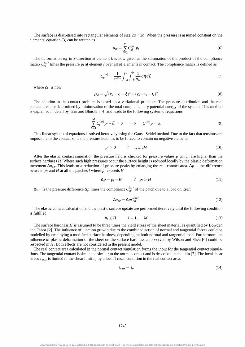
The surface is discretised into rectangular elements of size 2a×2b. When the pressure is assumed constant on theelements, equation (3) can be written as
uzk=M
∑l=1
C(zz)kl pl (6)
The deformationuzk in z-direction at elementk is now given as the summation of the product of the compliance
matrixC(zz)kl times the pressurepl at elementl over allM elements in contact. The compliance matrix is defined as
C(zz)kl =
1πE∗
∫ a
−a
∫ b
−b
1ρkl
dηdξ (7)
whereρkl is now
ρkl =√
(xk− xl − ξ )2+(yk− yl −η)2 (8)
The solution to the contact problem is based on a variationalprinciple. The pressure distribution and the realcontact area are determined by minimisation of the total complementary potential energy of the system. This methodis explained in detail by Tian and Bhushan [4] and leads to thefollowing system of equations
M
∑k=1
C(zz)kl pl − uz= 0 =⇒ C(zz)p= uz (9)
This linear system of equations is solved iteratively usingthe Gauss-Seidel method. Due to the fact that tensions areimpossible in the contact zone the pressure field has to be forced to contain no negative elements
pl ≥ 0 l = 1, ... ,M (10)
After the elastic contact simulation the pressure field is checked for pressure valuesp which are higher than thesurface hardnessH. Where such high pressures occur the surface height is reduced locally by the plastic deformationincrement∆uzp. This leads to a reduction of pressure peaks by enlarging thereal contact area.∆p is the differencebetweenpl andH at all the patchesl wherepl exceedsH
∆p= pl −H ∀ pl > H (11)
∆uzp is the pressure difference∆p times the complianceC(zz)kk of the patch due to a load on itself
∆uzp= ∆pC(zz)kk (12)
The elastic contact calculation and the plastic surface update are performed iteratively until the following conditionis fulfilled
pl ≤ H l = 1, ... ,M (13)
The surface hardnessH is assumed to be three times the yield stress of the sheet material as quantified by Bowdenand Tabor [2]. The influence of junction growth due to the combined action of normal and tangential forces could bemodelled by employing a modified surface hardness dependingon both normal and tangential load. Furthermore theinfluence of plastic deformation of the sheet on the surface hardness as observed by Wilson and Sheu [6] could berespected inH. Both effects are not considered in the present model.
The real contact area calculated in the normal contact simulation forms the input for the tangential contact simula-tions. The tangential contact is simulated similar to the normal contact and is described in detail in [7]. The local shearstressτmax is limited to the shear limitτo by a local Tresca condition in the real contact area.
τmax= τo (14)
1743
Downloaded 05 Nov 2012 to 131.188.201.33. Redistribution subject to AIP license or copyright; see http://proceedings.aip.org/about/rights_permissions

EXPERIMENTAL SETUP
As previously described, the ability to model numerically the different contact situations and thus the tribologicalconditions in sheet-bulk metal forming is important for thegeneral investigation of this new class of forming processes.To ensure the reliability of the developed simulation modelthe validation of the different stages of developmentis essential for this purpose. For the validation of the firststage of the simulation model a test rig for the in situinvestigation of flattening of sheet metal topographies under normal force and the strip drawing test were used.According to Bowden and Tabor [2] the real contact areaAreal between workpiece and tool is always smaller thanthe apparent contact areaAo, because of the roughness of workpiece and tool. For the development of a reliablenumerical model the consideration of elastic and plastic flattening in accordance to the surface load and the materialproperties is very important. To validate the numerical model concerning the flattening behaviour of sheet metalsurfaces under normal load a test rig with an ultrasonic measurement setup for in situ monitoring ofAreal/Ao wasused. Main component of the ultrasonic setup is a transceiver probe that is used for the measurement of changes ofAreal [8, 9]. The ultrasonic waves are emitted by the probe and propagate through the coupling medium water into thesteel punch and reach the contact of punch and workpiece. Thepropagation of ultrasonic waves is depending on thedifference in densities of the materials that are passed through. In case of no contact between punch and workpiece,there is transition from steel to air and thus a high difference in density, leading to reflection. When there is contactbetween punch and workpiece the ultrasonic waves are transmitted, because of the low density difference of the steel-steel pairing. By comparing emitted and reflected ultrasonic intensity, the increase ofAreal can be quantified. A sketchof the setup and the measurement principle is shown in figure 2. To be able to correlateAreal with measurement signalcalibration measurements were done. Additional information to the setup and its calibration can be found in [10].For the tests zinc coated DC04 sheet metal with an electro discharge texture (EDT) was used. The sheet was cleanedwith acetone (Dimethylketon) in an ultrasonic bath, to remove all anticorrosive oil from the surface, as the numericalmodel in the first stage of development is not able to considerthe effects of lubricants. For the tests the surface loadwas increased stepwise from 10 MPa, which is the lowest adjustable surface load, up to 380 MPa. The result of themeasurement is shown in the following section, where it is compared to the simulated flattening of the topography. Tobe able to simulate the flattening under normal load, the surface of the specimen was measured with a confocal whitelight microscopy in initial state. The data was used as inputfor the simulation.
As the strip drawing test is well established for determination of friction coefficients in sheet metal forming [11], itwas used to validate the simulation model concerning a virtual strip drawing test. In our case a two sided strip drawingtest is used, thus for the determination of the friction coefficient µ the drawing forceFF has to be divided by twice thenormal forceFN.
The dies are made from tool steel 1.3343, hardened to 62± 2 HR, and lapped to an arithmetic mean roughnessvalue ofSa = 0.22µm. As specimen uncoated EDT-structured DC04 strips with a length of 500 mm, a width of 300mm and a sheet thickness of 2 mm are used. The dies have a lengthof 100 mm and a width of 55 mm. Accordingto the boundary condition of the simulation model the strip drawing tests were run without lubrication. Because ofthe dry friction conditions and thus the risk of galling, lownormal loads of 3 and 5 MPa were chosen while having adrawing speed of 100 mm/s. The surface was measured in the initial state with a confocal white light microscopy andused as input data for the simulation. The results of the strip drawing test compared to the simulation are shown in thefollowing chapter.
Ultrasonic probe
Coupling medium
Specimen
Upper punch
Lower punch
Normal force
a)
Punch
Specimen
Contact
Emitted wave
Reflected wave
b)
FIGURE 2. Ultrasonic measurement setup (a) and measurement principle (b)
1744
Downloaded 05 Nov 2012 to 131.188.201.33. Redistribution subject to AIP license or copyright; see http://proceedings.aip.org/about/rights_permissions

RESULTS
Normal contact
The measured area-pressure curve shows a nonlinear behaviour for large pressures which is in agreement withthe findings of Pullen and Williamson [3]. They predict higher contact pressures than the surface hardnessH due tohydrostatic stress states underneath the surface. With higherAreal the interaction between the roughness asperities isrising, which promotes the development of hydrostatic stress states and consequently higher contact pressures.
In the numerical simulation the Young’s modulusE of the DC04 sheet was set to 205000 MPa and the Poisson’sratio ν was set to 0.34. According to the experimental findings of Bowden and Tabor the surface hardnessH wasset to three times the yield stressσy of the material. For the case of the DC04 sheet with a yield stress of 200 MPathis leads to a surface hardness of 600 MPa. The shear limitτo was set to 100 MPa according to the Tresca yieldcriterion. The simulations for elastic and plastic contactwere performed with 256 times 256 surface points and showa linear pressure-area relationship. For the elastic calculation this confirms the results of Archard [1]. However, dueto the extremely high local contact pressures, the elastic calculation can only be seen as a lower limit forAreal. Forthe plastic calculation, about 95% ofAreal is plastic contact area, so that the halfspace model predicts anAreal onlyslightly higher than the analytical model of Bowden and Tabor [2] (see eqn. 1). The model of Bowden and Tabor doesnot consider elastic contact areas where the pressure is below H so that it always predicts a lowerAreal than the plastichalfspace model. The halfspace model does not take into account contact pressures aboveH as observed by Pullenand Williamson, which would increase the real contact area.The influence of the elastic contact area should be smallbecause this area is small. Consequently the plastic contact simulation should give an upper approximation ofAreal.The soft zinc coat of the DC04 sheet can not be taken into account in the numerical model, so that the calculated realcontact area is lower than the measuredAreal even for the plastic calculation.
Surfaces get flattened in initial contact by plastic deformation. When surfaces are reloaded afterwards the contactis mostly elastic andAreal is significantly higher than in first contact. This is an important effect in sheet-bulk metalforming, where the sheet surface can be drawn from zones of high contact pressure to zones of lower contact pressure.The reloading simulations in figure 3b show this effect.
0 100 200 MPa 400
10
20
30
40
%
60
Pressure
Are
al
MeasurementPlastic simulation Elastic simulation
a)
0 20 40 60 MPa 100
5
10
%
20
Pressure
Are
al
MeasurementPlastic simulation Reloading sim. 1 Reloading sim. 2 Elastic simulation
b)
FIGURE 3. Pressure-area relationship (a) and pressure-area relationship in detail (b)
Tangential contact
Figure 4 compares friction coefficients measured in strip drawing tests with numerical results. The strip drawingtests were performed without lubrication and the numericalsimulation was done with the plastic model. For bothnormal pressures the numerical and the experimental value of the friction coefficient are in good agreement. Thenumerical values are only slightly higher than the experimental values. The value of the maximum shear stress (τo)in the real contact area can be considered as an upper bound ofthe real shear limit of the interface. This leads to theconclusion that the real contact area calculated in the plastic simulation is a quite good approximation of the reality.
1745
Downloaded 05 Nov 2012 to 131.188.201.33. Redistribution subject to AIP license or copyright; see http://proceedings.aip.org/about/rights_permissions

3 MPa 5 MPa0
0.05
0.1
0.15
0.2
0.25
Pressure
µ
n = 3
Measurement Simulation
FIGURE 4. Friction coefficients in strip drawing tests and numerics
CONCLUSION
The good agreement between the strip drawing tests and the numerical simulations show that the presentedhalfspace model is an adequate technique to simulate the contact of rough surfaces. The actual behaviour of roughnesspeaks depends on the three-dimensional stress state underneath the surface. Therefore it is necessary to improve themodelling of plastic deformation within the halfspace simulations. This is currently done by implementing three-dimensional plastic deformation using the von Mises yield criterion. Moreover the retarding effect of hydrostaticpressure in closed lubricant pockets on asperity flatteningis presently integrated into the halfspace model. Furthermeasurements with the existing and with other experimentalsetups are necessary to gain more knowledge of theinteraction of rough surfaces and to validate the simulation model.
ACKNOWLEDGMENTS
This research project is supported by the German Research Foundation (DFG) within the Transregional Collabo-rative Research Centre on sheet-bulk metal forming (SFB/TR73).
REFERENCES
1. J. F. Archard,Elastic deformation and the laws of friction. Proceedings of the Royal Society of London. Series A., Vol.243,pp. 190-205, 1957.
2. F. P. Bowden, D. Tabor,The friction and lubrication of solids. Oxford University Press, Oxford, 1986.3. J. Pullen, J. B. P. Williamson,On the plastic contact of rough surfaces. Proceedings of the Royal Society of London, Series A.,
Vol. 327, pp. 159-173, 1972.4. X. Tian, B. Bhushan,A Numerical Three-Dimensional Model for the Contact of Rough Surfaces by Variational Principle.
Journal of Tribology, Vol. 118, pp. 33-42, 1996.5. K. L. Johnson,Contact mechanics. Cambridge University Press, Cambridge, 1987.6. W. R. D. Wilson, S. Sheu,Real area of contact and boundary friction in metal forming. International Journal of Mechanical
Sciences, Vol. 30, pp. 475-489, 1988.7. K. Willner, Fully Coupled Frictional Contact Using Halfspace Theory. Journal of Tribology, Vol.130, 031405, 2008.8. M. Geiger, U. Engel, F. Vollertsen,In situ ultrasonic measurement of the real contact area in bulk metal forming. Ann. of the
CIRP, Vol. 41, Issue 1, pp. 255-258, 1992.9. S. Stancu-Niederkorn, U. Engel, M. Geiger,Ultrasonic Investigation of Friction Mechanism in Metal Forming. J. Mater.
Process. Technol., Vol. 45, Issue 1-4, pp. 623-618, 1994.10. M. Merklein, U. Engel, H. Vierzigmann,Novel setup for the investigation of tribological behaviorof sheet metal surfaces.
International Journal of Material Forming, Vol. 2, Issue 1,pp. 233-236, 2009.11. D. Schmoeckel, M. Prier, J. Staeves,Topography Deformation of Sheet Metal during the Forming Process and Its Influence on
Friction. Ann. of the CIRP, Vol. 46, Issue 1, pp. 175-178, 1997.
1746
Downloaded 05 Nov 2012 to 131.188.201.33. Redistribution subject to AIP license or copyright; see http://proceedings.aip.org/about/rights_permissions