numerical simulation of flow field characteristics in … · according to the turbulent mechanics,...
TRANSCRIPT

CHEMICAL ENGINEERING TRANSACTIONS
VOL. 59, 2017
A publication of
The Italian Association
of Chemical Engineering Online at www.aidic.it/cet
Guest Editors: Zhuo Yang, Junjie Ba, Jing Pan Copyright © 2017, AIDIC Servizi S.r.l. ISBN 978-88-95608- 49-5; ISSN 2283-9216
Numerical Simulation of Flow Field Characteristics In and Out of the Nozzle of Abrasive Water Jet
Lianhuan Guo*, Yudong Han
No. 260 Xikeng Road, Yongan 366000, China [email protected]
In the cutting system of abrasive water jet (AWJ), abrasive and water can be either pre-mixed or post-mixed. To compare the different properties of abrasive particle acceleration between the two mixing methods, we employed the FLUENT software to conduct numerical simulation on the flow fields of AWJ nozzle in both cases, and accordingly obtained the acceleration process of abrasive particles in the nozzle. Subsequently, the speed field and the turbulent kinetic energy were plotted in the distribution map, based on which we analyzed the causes to in-nozzle negative pressure and massive energy loss of the post-mix AWJ system. The corresponding result shows that: under the effect of the large-area vortex turbulence in the mixed cavity, a noticeable area of negative energy appears in the abrasive inlet, sucking abrasives in. In light of the small number of turbulent kinetic energy in the flow field of the nozzle in the pre-mix AWJ, and the low energy consumption in the acceleration process of AWJ, we theoretically validated the feasibility of chemical pipeline cutting by using the pre-mixed low-pressure AWJ.
1. Introduction Compared with the traditional mechanical cutting method, the abrasive water jet cutting technology is characterized by high energy, cold state and no such secondary effects as thermal stress, open fire and toxic gas. With its applicability to the fabrication and processing of most of metallic and non-metallic materials, AWJ cutting technology has served for a wide variety of fields like petrochemical engineering, mechanical processing and mining (Wang et al., 1999; Chen et al., 1996). However, a suite of well-equipped pressurization system is a necessity for the post-mixed AWJ cutting device to gain the pressure as high as 100-400MPa, which greatly complicate the cutting apparatus. When the on-site operation space is relatively narrow and closed (such as oil terminal facilities in caves or oil tanks buried underground), the facility has to be used in a much limited space, and thus fails to meet the requirements of emergency maintenance or rush repairs of chemical pipelines and oil tanks. Such being the case, demands appear for low-pressure AWJ cutting technology, whose rated pressure is reached under the effect of plunger pump instead of an extra pressurization system. In this way, the cutting facility is much more portable than otherwise. The pre-mixed AWJ system is capable of doing so. In the post-mixed abrasive water jet system, the high-pressure water is accelerated through the pure water nozzle, and the abrasive is accelerated by high-speed water flow in the mixing chamber. Then, they are combined into AWJ (Miller, 2012; Lv et al., 2013), as shown in Figure 1(a). In the pre-mixed abrasive water jet system, the high-pressure water and abrasive slurry are fully mixed in the pipeline before arriving at the nozzle, where they are simultaneously accelerated into high-speed AWJ, as shown in Figure 1(b). Relevant literature shows that abrasive particles in AWJ have a crucial part to play in removing target materials (Li et al., 2010). According to the law of conservation of energy, the material removal rate is positively proportional to the kinetic energy of the particle flow acted on the material, i.e.
ddd d
aEVK
t t=
(1)
DOI: 10.3303/CET1759179
Please cite this article as: Lianhuan Guo, Yudong Han, 2017, Numerical simulation of flow field characteristics in and out of the nozzle of abrasive water jet, Chemical Engineering Transactions, 59, 1069-1074 DOI:10.3303/CET1759179
1069

Where dEa represents the kinetic energy of the particle flow required for removal of the material whose volume is dV.
P
87
101
5
11
9
6
3
4 4
5
2
1
2
3 4
5 (a) The cutting system of the post-mixed AWJ (b) The cutting system of the pre-mixed AWJ
Figure 1: The diagram of the cutting systems in the two modes
2. Simulation of the post-mixed AWJ flow field 2.1 Establishment of the physical model
The principle of the post-mixed abrasive water jet is: the high-velocity small-diameter water jet is blended with the abrasive after entering the mixing chamber, and the mixture of AWJ enters the sandpipe nozzle (Swanson et at., 1987; Chen et al., 2012). Orthogonal hybrid structure is the common structure of nozzle. Figure 2 shows the two-dimensional physical model of the post-mixed AWJ cutting nozzle. The main structure parameters are: the inner diameter d1 of water nozzle, the inner diameter d2 of sandpipe, the diameter d3 of abrasive inlet, the inner diameter D of the mixing chamber, the length L of the mixing chamber, the distance D between the center of the abrasive inlet and the water nozzle, the length L of the sandpipe, the throat angle α of the sandpipe. Table 1 lists the details of structure size.
d1D
¦ ÁL1 d3
L
d2
L2
Figure 2: Modeling of the post-mixed abrasive water jet nozzle
Table 1: the size of the nozzle model
d1 d2 d3 D L L1 L2 Α 0.3 0.76 4 7.2 13 6.5 76 30°
2.2 Grid partition
Figure 3(a)-(b) expound the partition result of in-nozzle flow field calculation area by using square grids. Figure 3(a) is the grid partition of the entire area of the nozzle. As the grid partition is relatively dense, we choose part of the grid partition for display.
(a) (b)
Figure 3: grid partition of in-nozzle flow field area
10701070

2.3 Analysis of flow field simulation results
In the process of simulation calculation, the size and number of time steps are designed as 1E-7 seconds and 10,000, respectively. The maximum iteration number of each time step is 20, and the iteration computation is converged for 200,000 times. Our analysis target is the flow field at the iterative computation moment of 0.00175s. Figure 4 is the velocity vector of water phase in the post-mixing nozzle. Fig.5 is the nephogram of pressure distribution. Fig.6 is the distribution map of the turbulent kinetic energy.
Figure 4: Vector diagram of water phase velocity Figure 5: Nephogram of pressure distribution
Figure 6: Distribution map of turbulent kinetic energy
With entrapped air, the abrasive passes through the abrasive inlet and enters the mixing chamber, where it is blended with high-speed water flow. Under the action of the entrapped air, the velocity on the surface of the water flow becomes unsteady. According to the turbulent mechanics, there appears the phenomenon of entrainment around the jet, which will aggravate the instability of surface velocity. Furthermore, the additional mutation of the jet space will cause the jet to develop into vortex. The red marks in the water phase vector map in Figure 4 are large areas of noticeable vortex. As can be seen from it, they are mainly distributed in the upper part and lower part of the jet stream in the mixing chamber. Due to the existence of vortex turbulent, negative pressure appears in the mixing chamber. Figure 5 shows that the negative pressure area occupies a large proportion of the whole mixing chamber, and that a noticeable area of negative energy appears in the abrasive inlet, sucking abrasives in. The vortex turbulent itself will inevitably lead to massive loss of jet energy. As shown in Figure 6, the value of turbulent kinetic energy near the vortex core is relative large, reaching the magnitude order of 104m2/s2. We trace the abrasive particles of discrete phase, which is shown in Figure 7. The red circles in Figure 7 are the positions of concentrated collision.
Figure 7: Acceleration process of abrasive particle
Due to the exchange of momentum and energy between the abrasives, air and water, water flow decelerates and disperses over the whole space of the sandpipe, fully forming a three-phase flow. The deceleration is much obvious in that process. Specifically speaking, the inlet velocity of water flow is about 700m/s at 245MPa, while the outlet velocity is lowered down to 266m/s or so, and the outlet velocity of water is about 252m/s.
1071

3. Simulation of Pre-mixed AWJ flow field 3.1 The establishment of simulation model
The taper-shaped pre-mixed nozzle mainly consists of the cylindrical section and the contraction section. The simulation model is shown in Figure 8. Air domain is established outside of the nozzle, aimed at simulating the out-of-nozzle flow field in the ambient environment (Ye et al., 1998).
Figure 8: Simulation model Figure 9: Meshing of jet air domain
3.2 Grid partition
According to the three-dimensional model of nozzle and air domain, GAMBIT grid generation software is used to divide the model into hexahedral structured grids. The characteristics of the flow field outside the nozzle is our main concern in the simulation of flow field. Figure 9 is the grids of the out-of-nozzle air domain.
3.3 Settings of boundary conditions and solution methods
In light of the interphase force between water and abrasive, the Euler model is used as the multiphase flow model. In order to simulate the non-submerged jet condition, we let air be the primary phase and let abrasive and water be the secondary phase. The density of water is 998.2kg/m3 and the kinematic viscosity of water is about 1.006E-6m2/s. The abrasive grain is brown corundum, whose density and kinetic viscosity are 3970 kg/m3 and 1.85E-5m2/s, respectively. The size of the abrasive grain is 80 mesh, the volume percentage of the abrasive in AWJ is 1.9%.
3.4 Analysis of in-nozzle flow field simulation result
To facilitate analysis of flow field distribution results, we set the profile of the central axis of the 3D model as the research objective. Figure 10 is the distribution map of the pre-mixed in-nozzle turbulent kinetic energy. It can be seen that the pre-mixed turbulent kinetic energy in the flow field is relatively small, at the magnitude of 101m2/s2. This result indicates that there is merely a handful of energy loss of AWJ in the acceleration process.
Figure 10: distribution of turbulent kinetic energy
Figure 11(a)-(b) are the velocity nephograms of water and abrasive in the contraction section and the cylindrical section of the nozzle.
(a) The water velocity nephogram (b) The abrasive velocity nephogram
Figure 11: Velocity nephogram of in-nozzle flow field in the premixed mode
10721072

As can be seen from Figure 11, the high-pressure water carries abrasive forward to the cone-shaped contraction section of the nozzle at a low initial velocity, in which the mixture is accelerated. The acceleration rate is slow at the outset. However, as the pressure of the high-pressure water is gradually converted into kinetic energy in the more limited space of the contraction section, the acceleration rate increases constantly, rocketing at the end of the contraction section. The acceleration process of the abrasive speed is similar to that of water speed. The difference lies in the small-distance acceleration in the straight section of the nozzle, with a remarkable reduction in the magnitude of acceleration. There remains a certain difference of velocity between water and the abrasive in the acceleration process, which is broadened in the straight section. Figure 12 is the velocity change curves of water and abrasive along the axial line of the nozzle. As can be seen from it, the water velocity at the outlet of the nozzle has reached 201m/s under the pressure of 45MPa, and the abrasives have been accelerated to 177m/s.
Figure 12: Velocity change curve of water and abrasive along the axial line
3 cutting experiment of the portable AWJ facility in the pre-mixed mode Figure 13 is generation system of high-pressure water of the portable AWJ facility. Figure 14 is the specimen
of the pipeline steel slab X60, whose size is 200mm*100mm*20mm。
Figure 13: The generation system of portable AWJ high-pressure water
(a) Plan view of the specimen (b) local kerf of the specimen
Figure 14: Chemical pipeline steel specimen of X60
In the cutting experiment, the kerf should be long enough to ensure that the cutting depth can be measured in the steadily cutting area. Meanwhile, we measure the cutting depth for a total of three times, with the average value as the final value so that reducing error. Table 2 is the parameter settings of the experimental technique.
Table 2: Parameter Settings of experimental process
Parameter Unit Value Pressure, P MPa 25,30,35,40,45 Horizontal speed of movement, u mm/min 30,40,50,60,70
1073
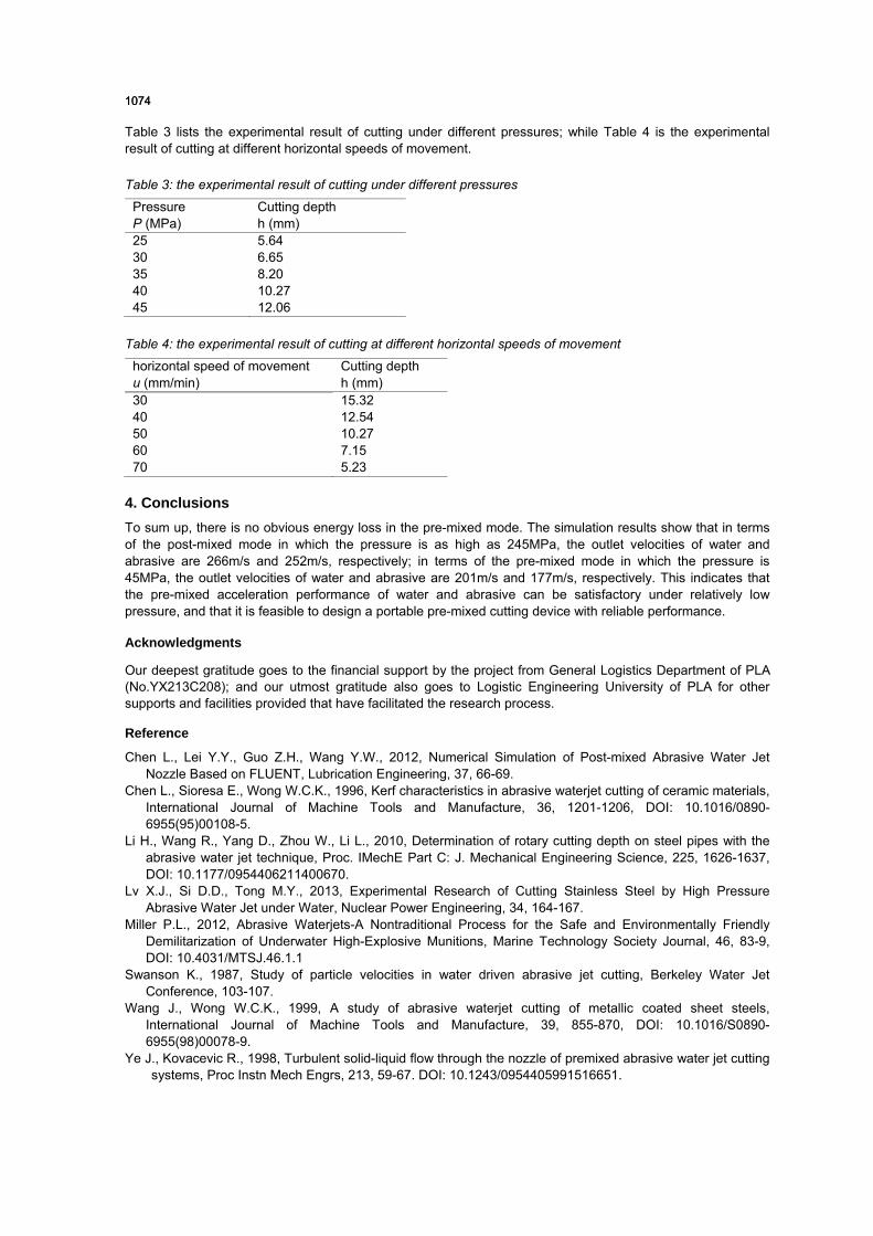
Table 3 lists the experimental result of cutting under different pressures; while Table 4 is the experimental result of cutting at different horizontal speeds of movement.
Table 3: the experimental result of cutting under different pressures
Pressure P (MPa)
Cutting depth h (mm)
25 5.64 30 6.65 35 8.20 40 10.27 45 12.06
Table 4: the experimental result of cutting at different horizontal speeds of movement
horizontal speed of movement u (mm/min)
Cutting depth h (mm)
30 15.32 40 12.54 50 10.27 60 7.15 70 5.23
4. Conclusions To sum up, there is no obvious energy loss in the pre-mixed mode. The simulation results show that in terms of the post-mixed mode in which the pressure is as high as 245MPa, the outlet velocities of water and abrasive are 266m/s and 252m/s, respectively; in terms of the pre-mixed mode in which the pressure is 45MPa, the outlet velocities of water and abrasive are 201m/s and 177m/s, respectively. This indicates that the pre-mixed acceleration performance of water and abrasive can be satisfactory under relatively low pressure, and that it is feasible to design a portable pre-mixed cutting device with reliable performance.
Acknowledgments
Our deepest gratitude goes to the financial support by the project from General Logistics Department of PLA (No.YX213C208); and our utmost gratitude also goes to Logistic Engineering University of PLA for other supports and facilities provided that have facilitated the research process.
Reference
Chen L., Lei Y.Y., Guo Z.H., Wang Y.W., 2012, Numerical Simulation of Post-mixed Abrasive Water Jet Nozzle Based on FLUENT, Lubrication Engineering, 37, 66-69.
Chen L., Sioresa E., Wong W.C.K., 1996, Kerf characteristics in abrasive waterjet cutting of ceramic materials, International Journal of Machine Tools and Manufacture, 36, 1201-1206, DOI: 10.1016/0890-6955(95)00108-5.
Li H., Wang R., Yang D., Zhou W., Li L., 2010, Determination of rotary cutting depth on steel pipes with the abrasive water jet technique, Proc. IMechE Part C: J. Mechanical Engineering Science, 225, 1626-1637, DOI: 10.1177/0954406211400670.
Lv X.J., Si D.D., Tong M.Y., 2013, Experimental Research of Cutting Stainless Steel by High Pressure Abrasive Water Jet under Water, Nuclear Power Engineering, 34, 164-167.
Miller P.L., 2012, Abrasive Waterjets-A Nontraditional Process for the Safe and Environmentally Friendly Demilitarization of Underwater High-Explosive Munitions, Marine Technology Society Journal, 46, 83-9, DOI: 10.4031/MTSJ.46.1.1
Swanson K., 1987, Study of particle velocities in water driven abrasive jet cutting, Berkeley Water Jet Conference, 103-107.
Wang J., Wong W.C.K., 1999, A study of abrasive waterjet cutting of metallic coated sheet steels, International Journal of Machine Tools and Manufacture, 39, 855-870, DOI: 10.1016/S0890-6955(98)00078-9.
Ye J., Kovacevic R., 1998, Turbulent solid-liquid flow through the nozzle of premixed abrasive water jet cutting systems, Proc Instn Mech Engrs, 213, 59-67. DOI: 10.1243/0954405991516651.
10741074