numerical simulation of advanced folded core … · numerical simulation of advanced folded core...
TRANSCRIPT

NUMERICAL SIMULATION OF ADVANCED FOLDED CORE MATERIALS FOR STRUCTURAL SANDWICH APPLICATIONS
S. Heimbsa, P. Middendorfb, S. Kilchertc, A.F. Johnsonc, M. Maierd
a EADS Innovation Works 21129 Hamburg, Germany
b EADS Innovation Works 85521 Ottobrunn, Germany
c German Aerospace Center (DLR) Institute of Structures and Design
70569 Stuttgart, Germany
d Institute for Composite Materials (IVW) Kaiserslautern University of Technology
67663 Kaiserslautern, Germany
OVERVIEW
The characterisation of the mechanical behaviour of folded core structures for advanced sandwich composites under flatwise compression load using a virtual testing approach is presented. In this context dynamic compression test simulations with the explicit solvers PAM-CRASH and LS-DYNA are compared to experimental data of two different folded core structures made of aramid paper and carbon fibre-reinforced plastic (CFRP). The focus of the investigations is the constitutive modelling of the cell wall material, the consideration of imperfections and the representation of cell wall buckling, folding or crushing phenomena. The consistency of the numerical results shows that this can be a promising and efficient approach for the determination of the effective mechanical properties and a cell geometry optimisation of folded core structures.
1. INTRODUCTION
Sandwich structures with fibre-reinforced plastic faces and a cellular core have a successful history as lightweight structures in aircraft design due to their superior stiffness-to-weight ratio. However, to date their field of exterior applications is limited to fairings and control surfaces so that the primary structure of an airliner has not been realised with sandwich materials yet. The main drawbacks are the accumulation of humidity, the complexity in manufacturing and the vulnerability against impact loads. In this context the aircraft manufacturer Airbus has presented a promising sandwich fuselage concept named VeSCo (Ventable Shear Core) [1-4], which incorporates folded structures as a sandwich core material. Such folded cores not only solve the problem of humidity accumulation due to their open ventilation channels, they can also be produced efficiently in a continuous process. The issue of impact vulnerability is currently addressed by the transnational project CELPACT (Cellular Structures for
Impact Performance), which is concentrating on advanced cellular core materials for potential applications in future primary aircraft structures with lower fabrication costs and improved impact performance. Besides other cellular materials, this project covers folded core structures with different geometries and different materials. In addition to experimental test series, investigations are focused on numerical simulation methods. Such numerical methods have proven their efficiency and reliability in the past in impact simulations on sandwich structures with honeycomb cores [5, 6] and folded cores [7-9]. In order to be able to evaluate the impact performance of a sandwich core material, knowledge of the nonlinear, effective mechanical properties especially for flatwise compression and transverse shear is required. Including a large number of different folded core geometries in such a study makes the experimental determination of these properties time and cost consuming. Much more desirable is a numerical determination method using meso-models and virtual testing simulations in order to get the effective stress-strain data. Recently, this virtual testing approach has successfully been applied to folded core structures [10]. However, the development and validation of adequate meso-models poses different challenges. These are addressed in this paper that covers the investigation of the flatwise compression behaviour of folded core structures.
2. FOLDED CORE STRUCTURES
In the focus of this paper are two different types of folded core that differ regarding to their geometry, material and fabrication process.
One is made of phenolic resin-impregnated aramid (Kevlar®) paper and produced in a continuous process (FIG. 1 bottom). This process involves the embossing of the folding edges onto the flat sheet material and subsequent folding into the final geometry [11, 12].

The other type is made of a carbon fibre-reinforced plastic (CFRP) laminate in a [0°/90°/0°] lay-up (FIG. 1 top). This folded core is produced in a discontinuous process by forming the flat sheet between two matrices [13]. But in contrast to deep drawing, the matrices are transformable so that the prepreg material is folded without being elongated. The top and bottom folding pattern is a simple zigzag shape and therefore slightly different to the aramid paper foldcore’s geometry.
3. EXPERIMENTAL TESTING OF FOLDED CORE
For verification of the numerical simulations and in order to evaluate the characteristics of the structural behaviour of the respective folded core types, basic compression tests according to DIN 53291 (FIG. 2) were performed. For this purpose an Instron universal testing machine was used in combination with a laser-controlled displacement measurement system. The stress was calculated using the effective area of the specimens, which is defined as the area projected at the plane perpendicular to the compression direction. The experiments showed that there exists a fundamental difference in the structural behaviour between both materials:
The aramid paper folded core failed with a buckling and folding pattern under compressive loads comparable to the one observed for aramid honeycomb cores [14], which leads to a corresponding stress-strain diagram (FIG. 3).
0
1
2
3
4
0 20 40 60
compressive strain [%]
com
pres
sive
str
ess
[MPa
]
collapse zone
densificationpeak
0%
5%
15%
After an elastic deformation behaviour the cell walls buckle and the edges start kinking (FIG. 4), which is accompanied by a large drop in the stress level. In the subsequent collapse zone the cell walls are folding. For larger deformations the stress is increasing again, which is due to the beginning of the load to be transmitted by paper-to-paper contacts up to the densification regime. This is characterised by a steep slope in the diagram.
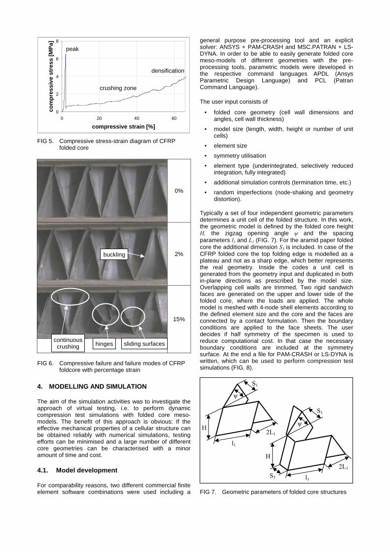
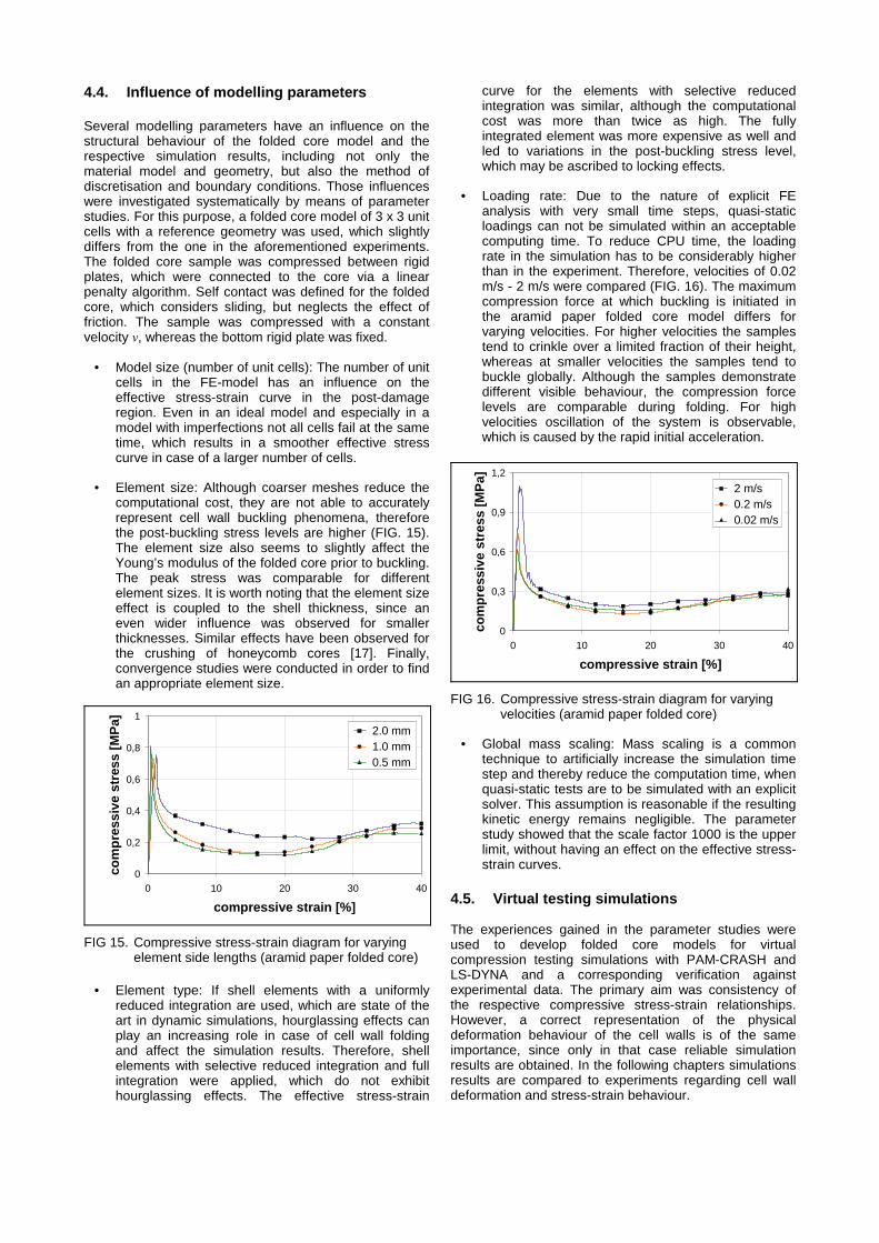
In case of the CFRP folded core a slight cell wall buckling was also visible followed by a compression fracture at a remarkably higher stress level. The drop in the stress-strain-diagram is considerably steeper than for the aramid paper foldcore (FIG. 5). There are three different phenomena which determine the post-damage behaviour (FIG. 6): 1. sliding of the surfaces after failure in the cell wall middle, 2. formation of hinges through residual intact layers after failure in the cell wall middle and 3. continuous crushing after failure at the cell wall top and bottom. The higher the compressive strains, the more predominant is the third phenomenon and this cumulative crushing and fragmentation of the cell walls leads to an increasing stress level before densification.
FIG 1. Examples of folded core structures made of CFRP (top) and phenolic resin-impregnated aramid paper (bottom)
FIG 2. Compression testing with laser-controlled displacement measurement
FIG 3. Compressive stress-strain diagram of aramid paper folded core
FIG 4. Compressive failure and failure modes of aramid paper foldcore with percentage strain
Laser
buckling
folding/kinking
0
2
4
6
8
0 20 40 60
compressive strain [%]
com
pres
sive
str
ess
[MPa
]peak
crushing zone
densification
0%
2%
15%
4. MODELLING AND SIMULATION
The aim of the simulation activities was to investigate the approach of virtual testing, i.e. to perform dynamic compression test simulations with folded core meso-models. The benefit of this approach is obvious: If the effective mechanical properties of a cellular structure can be obtained reliably with numerical simulations, testing efforts can be minimised and a large number of different core geometries can be characterised with a minor amount of time and cost.
4.1. Model development
For comparability reasons, two different commercial finite element software combinations were used including a
general purpose pre-processing tool and an explicit solver: ANSYS + PAM-CRASH and MSC.PATRAN + LS-DYNA. In order to be able to easily generate folded core meso-models of different geometries with the pre-processing tools, parametric models were developed in the respective command languages APDL (Ansys Parametric Design Language) and PCL (Patran Command Language).
The user input consists of
• folded core geometry (cell wall dimensions and angles, cell wall thickness)
• model size (length, width, height or number of unit cells)
• element size
• symmetry utilisation
• element type (underintegrated, selectively reduced integration, fully integrated)
• additional simulation controls (termination time, etc.)
• random imperfections (node-shaking and geometry distortion).
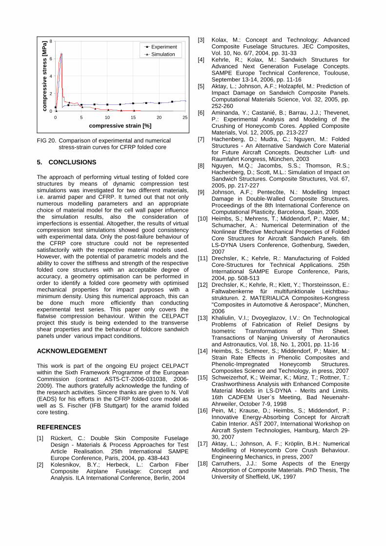
Typically a set of four independent geometric parameters determines a unit cell of the folded structure. In this work, the geometric model is defined by the folded core height H, the zigzag opening angle ψ and the spacing parameters l1 and L1 (FIG. 7). For the aramid paper folded core the additional dimension S3 is included. In case of the CFRP folded core the top folding edge is modelled as a plateau and not as a sharp edge, which better represents the real geometry. Inside the codes a unit cell is generated from the geometry input and duplicated in both in-plane directions as prescribed by the model size. Overlapping cell walls are trimmed. Two rigid sandwich faces are generated on the upper and lower side of the folded core, where the loads are applied. The whole model is meshed with 4-node shell elements according to the defined element size and the core and the faces are connected by a contact formulation. Then the boundary conditions are applied to the face sheets. The user decides if half symmetry of the specimen is used to reduce computational cost. In that case the necessary boundary conditions are included at the symmetry surface. At the end a file for PAM-CRASH or LS-DYNA is written, which can be used to perform compression test simulations (FIG. 8).
FIG 5. Compressive stress-strain diagram of CFRP folded core
FIG 6. Compressive failure and failure modes of CFRP foldcore with percentage strain
FIG 7. Geometric parameters of folded core structures
H
l1
2L1
S1
ψ
H
l1
2L1
S1
S3
ψ
sliding surfaceshinges continuous crushing
buckling

4.2. Imperfections
So far the meso-scale models have a uniformly perfect geometry. In reality no cellular structure is neither uniform in geometry nor free of imperfections and irregularities. This affects the buckling load of the single cell walls and the whole structure’s strength. Therefore, a meso-scale model without imperfections will always lead to an overestimation of stiffness and strength values.
In this work two different approaches to account for imperfections in the FE-models were investigated:
One way is to include the actual imperfections in the model. Global geometric imperfections can be modelled by randomly distorting the foldcore geometry prior to meshing (FIG. 9). Local imperfections like uneven cell walls can be represented by randomly modifying all node’s coordinates (‘node-shaking’, FIG. 10). Both features were included in the parametric models based on random numbers. This is a reasonable approach towards reality, but still does not account for all possible imperfections.
The other way is to keep the ideal mesh and reduce the cell wall properties in such a way that the effective structural behaviour matches experimental data. This inverse approach requires basic experimental data of the folded core. These data are the target values, while the cell wall’s thickness as well as stiffness and strength are defined as parameters. Within a parameter identification loop with an optimisation software, compression and shear test simulations are performed in order to determine the set of parameters with the best correlation to the target values. Hereby, the lack of imperfections in the FE-model is compensated by the use of cell wall properties that are on purpose lower than in reality.
Both approaches were applied to the folded core models. Preliminary investigations on the CFRP cores showed that the imperfections in the model by geometry distortion or node-shaking reduce the global compressive strength, but not in a sufficient way that the simulation results of virtual compression tests agree with experimental data. On the other hand, the reduction of the mechanical properties and cell wall thickness led to a very good consistence, while still maintaining a realistic buckling pattern in the simulation. Reality is a combination of both: There are geometrical imperfections in the cellular structure and there are variations in the material properties and the paper thickness, especially in case of impregnated aramid
paper. The weakest or thinnest areas of a cell wall determine the global properties, since damage will start from these areas, which justifies the approach of reducing the average values in the model.
4.3. Cell wall material modelling
4.3.1. Aramid paper folded core
The aramid foldcore paper is made of randomly oriented Kevlar® fibres, which are impregnated with a phenolic resin (FIG. 11), similar to the cell wall paper of prevalent honeycomb cores. The mechanical behaviour of the paper is slightly orthotropic due to the milling process during fabrication. IFB Stuttgart and DLR examined the tensile behaviour of this aramid paper in a cooperative test program. FIG. 12 shows tensile stress-strain curves of uniaxially loaded aramid paper samples. The paper samples were loaded parallel and transversal to the milling direction. One characteristic observed by optical strain measurement was a strongly varying in-plane strain distribution over the paper area. This is probably caused by varying paper thickness and fibre dispensation. The tensile behaviour of the implemented material model was adapted to the experimental results. It was assumed to be isotropic and linear elastic until failure, whereas the line of best fit was adjusted to the stress-strain curves of both material directions. The shear properties were calculated from the tensile behaviour.
FIG. 8. FE-models of CFRP (top) and aramid paper (bottom) folded core
FIG 9. Imperfections through geometry distortion: a) none, b) 1 mm maximum distortion
FIG 10. Imperfections through node-shaking: a) none, b) 0.05 mm, c) 0.1 mm maximum distortion
a) b)
a) b) c)

0
30
60
90
120
0,0 0,5 1,0 1,5 2,0 2,5
tensile strain [%]
tens
ile s
tres
s [M
Pa]
Longitudinal Transverse
The aramid paper exhibits different mechanical properties for tension and compression, analogue to other fibre reinforced composites. Generally, it is difficult to measure the compressive properties of the aramid paper. Single paper sheets will buckle before the maximum compressive stress is met. In the case of thicker layered aramid paper samples the interface effects are uncertain. In FIG. 13 the compressive stress-strain diagram of a small, thick-walled cylinder made of several layers of aramid paper under compression is shown. The cylinder is elastically compressed until maximum load. It is noted, that the maximum compressive stress is about half the level of the maximum tensile stress in FIG. 12. Subsequently, the cylinder begins to crush around a ring-shaped initial zone at a constant stress level. The cylinder demonstrated only negligible buckling.
0
15
30
45
60
0 2 4 6 8 10
compressive strain [%]
com
pres
sive
str
ess
[MPa
]
peak
crushing zone
A rough estimate for the compressive paper behaviour was made based on the compressive cylinder test: The virtually constant crushing stress was assumed to indicate a “pseudo-plastic” material behaviour of the aramid paper for compressive loads, if buckling can be neglected. This was implemented into the material model, such that the paper deforms linearly elastic until the crushing stress is met and then behaves perfectly plastic.
The aramid paper was modelled with an isotropic material model in PAM-CRASH (material type 116). This is based on a linear elastic-perfectly plastic constitutive law with different behaviour for tensile and compressive loads. The material properties were used from the aforementioned experiments, the paper thickness was 0.35 mm. Local imperfections were incorporated by applying the node-shaking approach.
4.3.2. CFRP folded core
The CFRP folded core was modelled and simulated with LS-DYNA. Since the cell walls are a laminate with a [0°/90°/0°] lay-up of three unidirectional layers, a user-defined integration rule with three integration points across the thickness of each shell element was applied. The orthotropic composite material model MAT54 in LS-DYNA was used for the CFRP material. Each integration point represents one layer and is characterised by the respective fibre angle. Material model MAT54 is based on a linear elastic constitutive law with failure criteria by Chang-Chang. Additionally, failure strains are introduced, which control element layer erosion. The crush-front algorithm of MAT54 was also used, which reduces the strength of elements neighbouring eroded elements to facilitate the representation of a pre-damage and a progressing crushing [15, 16].
The material properties of the single unidirectional layers were taken from data sheets of the manufacturer, the total cell wall thickness of 0.35 mm was measured using micrographs (FIG. 14). These values in combination with an ideal FE-model led to an overestimation of the effective compressive strength in virtual compression test simulations. The incorporation of global and local imperfections in the folded core model only had a minor influence, taking into account that the actual degree of imperfections in the CFRP laminate is noticeably lower than in the phenolic-impregnated aramid paper. Therefore, in contrast to the aramid paper foldcore model, the lamina stiffness was slightly reduced maintaining the actual cell wall thickness to achieve consistence with experimental compression stress curves.
FIG 11. Micrographs of front folding edge (left) and random fibres in aramid paper (right)
FIG 12. Tensile stress-strain diagram of aramid paper samples
FIG 13. Compressive stress-strain diagram of an aramid paper cylinder
FIG 14. Micrographs of top folding edge (left) and CFRP cell wall laminate (right)
phenolic resin
aramid paper
0° 90° 0°
t=0,
35 m
m
4.4. Influence of modelling parameters
Several modelling parameters have an influence on the structural behaviour of the folded core model and the respective simulation results, including not only the material model and geometry, but also the method of discretisation and boundary conditions. Those influences were investigated systematically by means of parameter studies. For this purpose, a folded core model of 3 x 3 unit cells with a reference geometry was used, which slightly differs from the one in the aforementioned experiments. The folded core sample was compressed between rigid plates, which were connected to the core via a linear penalty algorithm. Self contact was defined for the folded core, which considers sliding, but neglects the effect of friction. The sample was compressed with a constant velocity v, whereas the bottom rigid plate was fixed.
• Model size (number of unit cells): The number of unit cells in the FE-model has an influence on the effective stress-strain curve in the post-damage region. Even in an ideal model and especially in a model with imperfections not all cells fail at the same time, which results in a smoother effective stress curve in case of a larger number of cells.
• Element size: Although coarser meshes reduce the computational cost, they are not able to accurately represent cell wall buckling phenomena, therefore the post-buckling stress levels are higher (FIG. 15). The element size also seems to slightly affect the Young’s modulus of the folded core prior to buckling. The peak stress was comparable for different element sizes. It is worth noting that the element size effect is coupled to the shell thickness, since an even wider influence was observed for smaller thicknesses. Similar effects have been observed for the crushing of honeycomb cores [17]. Finally, convergence studies were conducted in order to find an appropriate element size.
0
0,2
0,4
0,6
0,8
1
0 10 20 30 40
compressive strain [%]
com
pres
sive
str
ess
[MPa
]
2.0 mm 1.0 mm 0.5 mm
• Element type: If shell elements with a uniformly reduced integration are used, which are state of the art in dynamic simulations, hourglassing effects can play an increasing role in case of cell wall folding and affect the simulation results. Therefore, shell elements with selective reduced integration and full integration were applied, which do not exhibit hourglassing effects. The effective stress-strain
curve for the elements with selective reduced integration was similar, although the computational cost was more than twice as high. The fully integrated element was more expensive as well and led to variations in the post-buckling stress level, which may be ascribed to locking effects.
• Loading rate: Due to the nature of explicit FE analysis with very small time steps, quasi-static loadings can not be simulated within an acceptable computing time. To reduce CPU time, the loading rate in the simulation has to be considerably higher than in the experiment. Therefore, velocities of 0.02 m/s - 2 m/s were compared (FIG. 16). The maximum compression force at which buckling is initiated in the aramid paper folded core model differs for varying velocities. For higher velocities the samples tend to crinkle over a limited fraction of their height, whereas at smaller velocities the samples tend to buckle globally. Although the samples demonstrate different visible behaviour, the compression force levels are comparable during folding. For high velocities oscillation of the system is observable, which is caused by the rapid initial acceleration.
0
0,3
0,6
0,9
1,2
0 10 20 30 40
compressive strain [%]
com
pres
sive
str
ess
[MPa
] 2 m/s 0.2 m/s 0.02 m/s
• Global mass scaling: Mass scaling is a common technique to artificially increase the simulation time step and thereby reduce the computation time, when quasi-static tests are to be simulated with an explicit solver. This assumption is reasonable if the resulting kinetic energy remains negligible. The parameter study showed that the scale factor 1000 is the upper limit, without having an effect on the effective stress-strain curves.
4.5. Virtual testing simulations
The experiences gained in the parameter studies were used to develop folded core models for virtual compression testing simulations with PAM-CRASH and LS-DYNA and a corresponding verification against experimental data. The primary aim was consistency of the respective compressive stress-strain relationships. However, a correct representation of the physical deformation behaviour of the cell walls is of the same importance, since only in that case reliable simulation results are obtained. In the following chapters simulations results are compared to experiments regarding cell wall deformation and stress-strain behaviour.
FIG 15. Compressive stress-strain diagram for varying element side lengths (aramid paper folded core)
FIG 16. Compressive stress-strain diagram for varying velocities (aramid paper folded core)

4.5.1. Aramid paper folded core
The PAM-CRASH model consisted of 5 x 13 unit cells of the aramid folded core structure. FIG. 17 illustrates the cell wall deformation in the simulation, while the corresponding compressive stress-strain curves of experiment and simulation are given in FIG. 18. In both cases the folded core structure deforms elastically up to the peak load. The maximum stress is lower for the simulation compared to the experiment. This was to be expected, as the stress peak observed in the cylinder tests was cut off due to the elastic-perfectly plastic constitutive formulation used in the material model.
0%
5%
15%
0
1
2
3
4
0 20 40 60
compressive strain [%]
com
pres
sive
str
ess
[MPa
]
Experiment Simulation
The stress-strain curve indicates a good agreement within the collapse zone, which is dominated by folding and kinking. The cell wall collapse in experiment and simulation occurs at similar strain values. Subsequently,
the edges buckle at likewise comparable strains. The folds observed within the experiment tended to form sharp kinks, whereas the folds in the simulation buckled in a sinusoidal shape. Nevertheless, the overall folding pattern in the simulation model agrees very well to the experiment. Following the stress-strain curve, the simulation showed a softer behaviour compared to the experiment for high compressive strains. This difference was attributed to the neglected friction in the simulation. For increasing contact forces friction is expected to exhibit a larger effect on the foldcore compressive behaviour.
4.5.2. CFRP folded core
The FE analysis of CFRP folded core structures differs significantly from the one of aramid paper foldcore, where the buckling and folding of the paper cell walls could be represented with a high degree of accuracy. Challenging tasks arise regarding modelling of the CFRP cell wall crushing in the post-failure region. The three different cell wall behaviours that were described in the experimental chapter, i.e. sliding, hinge formation and crushing, could not be adopted in one model at the same time. FIG. 19 shows one single cell under compression load, the nodes on the cell edges have boundary conditions inhibiting lateral translations. First the cell walls slightly buckle according to experimental observations, then the material fails under compression starting from the cell wall edges. The respective elements are eroded in a propagating horizontal crack. Once a complete row of elements is deleted, the compression force drops to zero. Due to the angular geometry of the folded core cell, the elements do not come into contact again. The force does not increase until the upper and lower halves of the failed foldcore have contact with the compression plates. That is why the post-damage behaviour, which is of importance for impact simulations, can not be represented correctly with this approach. Different simulations were performed introducing a row of trigger elements with lower strength values at the top of the unit cell intending a continuous crushing by means of the crush-front algorithm in the LS-DYNA material model MAT54. But still the model failed row by row leading to respective compression force drops to zero. Such FE-simulations of in-plane crushing of composite materials have been pointed out as problematic tasks before [16, 18]. However, the elastic and buckling behaviour as well as the maximum stress level could be modelled with an acceptable consistency (FIG. 20).
FIG 17. Aramid paper cell wall deformation in simulation with percentage strain
FIG 18. Comparison of experimental and numerical compressive stress-strain curves for aramid paper folded core
FIG 19. CFRP unit cell under compression: a) initial configuration, b) cell wall buckling, c) first failed elements, d) complete cell wall failure, e)-f) crushing
a b c d e f
buckling
folding/kinking
0
2
4
6
8
0 5 10 15 20 25
compressive strain [%]
com
pres
sive
str
ess
[MPa
] Experiment Simulation
5. CONCLUSIONS
The approach of performing virtual testing of folded core structures by means of dynamic compression test simulations was investigated for two different materials, i.e. aramid paper and CFRP. It turned out that not only numerous modelling parameters and an appropriate choice of material model for the cell wall paper influence the simulation results, also the consideration of imperfections is essential. Altogether, the results of virtual compression test simulations showed good consistency with experimental data. Only the post-failure behaviour of the CFRP core structure could not be represented satisfactorily with the respective material models used. However, with the potential of parametric models and the ability to cover the stiffness and strength of the respective folded core structures with an acceptable degree of accuracy, a geometry optimisation can be performed in order to identify a folded core geometry with optimised mechanical properties for impact purposes with a minimum density. Using this numerical approach, this can be done much more efficiently than conducting experimental test series. This paper only covers the flatwise compression behaviour. Within the CELPACT project this study is being extended to the transverse shear properties and the behaviour of foldcore sandwich panels under various impact conditions.
ACKNOWLEDGEMENT
This work is part of the ongoing EU project CELPACT within the Sixth Framework Programme of the European Commission (contract AST5-CT-2006-031038, 2006-2009). The authors gratefully acknowledge the funding of the research activities. Sincere thanks are given to N. Voll (EADS) for his efforts in the CFRP folded core model as well as S. Fischer (IFB Stuttgart) for the aramid folded core testing.
REFERENCES [1] Rückert, C.: Double Skin Composite Fuselage
Design - Materials & Process Approaches for Test Article Realisation. 25th International SAMPE Europe Conference, Paris, 2004, pp. 438-443
[2] Kolesnikov, B.Y.; Herbeck, L.: Carbon Fiber Composite Airplane Fuselage: Concept and Analysis. ILA International Conference, Berlin, 2004
[3] Kolax, M.: Concept and Technology: Advanced Composite Fuselage Structures. JEC Composites, Vol. 10, No. 6/7, 2004, pp. 31-33
[4] Kehrle, R.; Kolax, M.: Sandwich Structures for Advanced Next Generation Fuselage Concepts. SAMPE Europe Technical Conference, Toulouse, September 13-14, 2006, pp. 11-16
[5] Aktay, L.; Johnson, A.F.; Holzapfel, M.: Prediction of Impact Damage on Sandwich Composite Panels. Computational Materials Science, Vol. 32, 2005, pp. 252-260
[6] Aminanda, Y.; Castanié, B.; Barrau, J.J.; Thevenet, P.: Experimental Analysis and Modeling of the Crushing of Honeycomb Cores. Applied Composite Materials, Vol. 12, 2005, pp. 213-227
[7] Hachenberg, D.; Mudra, C.; Nguyen, M.: Folded Structures - An Alternative Sandwich Core Material for Future Aircraft Concepts. Deutscher Luft- und Raumfahrt Kongress, München, 2003
[8] Nguyen, M.Q.; Jacombs, S.S.; Thomson, R.S.; Hachenberg, D.; Scott, M.L.: Simulation of Impact on Sandwich Structures. Composite Structures, Vol. 67, 2005, pp. 217-227
[9] Johnson, A.F.; Pentecôte, N.: Modelling Impact Damage in Double-Walled Composite Structures. Proceedings of the 8th International Conference on Computational Plasticity, Barcelona, Spain, 2005
[10] Heimbs, S.; Mehrens, T.; Middendorf, P.; Maier, M.; Schumacher, A.: Numerical Determination of the Nonlinear Effective Mechanical Properties of Folded Core Structures for Aircraft Sandwich Panels. 6th LS-DYNA Users Conference, Gothenburg, Sweden, 2007
[11] Drechsler, K.; Kehrle, R.: Manufacturing of Folded Core-Structures for Technical Applications. 25th International SAMPE Europe Conference, Paris, 2004, pp. 508-513
[12] Drechsler, K.; Kehrle, R.; Klett, Y.; Thorsteinsson, E.: Faltwabenkerne für multifunktionale Leichtbau-strukturen. 2. MATERIALICA Composites-Kongress "Composites in Automotive & Aerospace", München, 2006
[13] Khaliulin, V.I.; Dvoyeglazov, I.V.: On Technological Problems of Fabrication of Relief Designs by Isometric Transformations of Thin Sheet. Transactions of Nanjing University of Aeronautics and Astronautics, Vol. 18, No. 1, 2001, pp. 11-16
[14] Heimbs, S.; Schmeer, S.; Middendorf, P.; Maier, M.: Strain Rate Effects in Phenolic Composites and Phenolic-Impregnated Honeycomb Structures. Composites Science and Technology, in press, 2007
[15] Schweizerhof, K.; Weimar, K.; Münz, T.; Rottner, T.: Crashworthiness Analysis with Enhanced Composite Material Models in LS-DYNA - Merits and Limits. 16th CADFEM User`s Meeting, Bad Neuenahr-Ahrweiler, October 7-9, 1998
[16] Pein, M.; Krause, D.; Heimbs, S.; Middendorf, P.: Innovative Energy-Absorbing Concept for Aircraft Cabin Interior. AST 2007, International Workshop on Aircraft System Technologies, Hamburg, March 29-30, 2007
[17] Aktay, L.; Johnson, A. F.; Kröplin, B.H.: Numerical Modelling of Honeycomb Core Crush Behaviour. Engineering Mechanics, in press, 2007
[18] Carruthers, J.J.: Some Aspects of the Energy Absorption of Composite Materials. PhD Thesis, The University of Sheffield, UK, 1997
FIG 20. Comparison of experimental and numerical stress-strain curves for CFRP folded core