numerical modelling of the cyclic behaviour of...
TRANSCRIPT

1
NUMERICAL MODELLING OF THE CYCLIC BEHAVIOUR OF TIMBER-FRAMED STRUCTURES
R. Lukic, E. Poletti, H. Rodrigues, G. Vasconcelos,
Abstract:
The present paper presents a study on the applicability of numerical models in predicting the global
response of timber-framed shear walls during earthquake events. Based on previous in-plane cyclic
testing of traditional timber frames with and without masonry infill, numerical models were developed to
describe the cyclic response of traditional timber frame walls including flexural behaviour, pinching and
strength degradation. The numerical models were developed in the finite element software OpenSees
with calibrated springs representing nailed connectors found in traditional half lap joints. Based on the
calibrated models a study was conducted on the timber frame wall with brick infill model by varying wall
configuration and analysing cumulative energy dissipation and the effect of slenderness and load capacity
with increasing drift. A good correspondence was obtained with the experimental data and future
work will include the application of the model to whole buildings.
Keywords: Timber construction; Earthquake engineering; Seismic design; Ductility.
Authors:
Relja Lukic
Ojdrovic Engineering, Toronto, Canada
Elisa Poletti
ISISE, Department of Civil Engineering, Campus de Azurém, University of Minho, Portugal
(corresponding author)
Graça Vasconcelos
ISISE, Department of Civil Engineering, Campus de Azurém, University of Minho, Portugal.
Hugo Rodrigues

2
RISCO, School of Technology and Management, Instituto Politécnico de Leiria, Portugal

3
1. Introduction
Ancient heritage is abundant with timber-framed structures that function as either shear walls within
masonry buildings or as independent structural systems, resisting both lateral loads and gravity
loads. In earthquake prone areas they have been used as seismic-resistant construction and their good
behaviour during seismic events has been documented and observed in several countries (e.g. Portugal,
Italy, Greece, Turkey, Peru and Haiti) [1] [2] [3] [4].
Timber shear wall systems are typically composed of internal braces forming an X-shape called the
Cross of St. Andrew and are typically found in seismic countries such as in Italy and Portugal. Portuguese
Pombalino buildings, introduced after the 1755 earthquake and subsequent tsunami and fire by the prime
minister of the time, the Marquis of Pombal, consist of external load bearing masonry walls and internal
timber-framed shear walls (Figure 1a), called frontal walls [5]. Even though the city has not experienced
significant seismic activity since 1755 (the return period is estimated to be 250 years), the seismic
effectiveness of these buildings is unknown. However, it is expected that the seismic performance of
Pombalino buildings is directly dependent on the timber frame walls and, thus, it is important to
understand their mechanical behaviour.
In Italy, the so called “casa baraccata”, introduced after the 1783 earthquake by the Borbone house,
has a timber frame also embedded in the exterior masonry walls [2]. Timber frame shear walls are
encountered in several other countries, especially in the local vernacular architecture, and can be
composed of various infill materials, ranging from brick and stone masonry to mud and cane. The timber
is not only able to better resist horizontal loads, but it also provides a confining effect on the masonry
structure improving its mechanical properties [6]. In Greece and Turkey a variety of timber-framed
structures can be found [1] [7] and they have proved to resist well to seismic actions when appropriately
maintained. The same can be said for other Balkan countries, e.g. Romania and Albania. Timber framed
construction (quincha construction) in Peru also proved its efficiency during seismic events [8] [9]. In this
case, the walls are lighter and are infilled with interwoven bamboo canes. Quincha is used for upper
floors, while the ground floor of traditional buildings is usually in adobe.
Timber frame construction systems are also present in typical vernacular architecture in non-seismic
regions, such as Germany, France, the UK, and in general all northern European countries [10] [11].

4
There is a great variability in terms of geometry, with bracing elements in the corners. Often, additional
timber members are used as decorations, being also rounded (Figure 1b).
(a)
(b)
Figure 1 (a) Frontal walls in (a) Pombalino building (© Stellacci) and (b) timber-framed house in York, UK,
XVI century (© Poletti).
The connections on timber frame construction are a key issue, as they control the in-plane behavior,
particularly as regards the dissipative capacity of the timber walls. As there are very different types of
connections, it is expected that different dissipative behavior is found, and this justifies the experimental
research work that has been carried out in the last years on different timber frame systems [2] [9] [12] [13]
[14] [15] [16] [17]. Scarcer works are available from a numerical point of view. Kouris and Kappos [18]
performed non-linear numerical analyses on traditional Portuguese half-timbered walls, first performing a
detailed modelling of a wall, considering non-linear properties for the materials and modelling the contacts
in timber elements and subsequently creating a simplified model using beam and link elements. Quinn et
al. [9] modelled traditional Peruvian timber frame walls adopting semi-rigid spring elements to model the
mortise and tenon connections of the wall. The springs were calibrated based on experimental results by
using the components method, which is an analytical method that allows to calculate the joint
stiffness assuming a semi-rigid model taking into account all the components of the loads
(normal, shear and bending) [19]. Ceccotti and Sandhaas [20] used a hysteretic law to analyse the
behavior of traditional timber frame walls. In the numerical model, the walls are represented by lumped
masses and rotational springs and rigid elements represent the timber elements, being the global cyclic

5
behaviour of the wall given only by the behavior of the springs. For modelling a traditional Pombalino wall,
Meireles et al. [16] introduced an analytical hysteretic law in a finite element software to describe the
connections represented by means of spring elements. A macro-element was then developed to
represent the frontal walls inside a masonry building. The hysteretic law was also implemented in an
existing finite element model for other timber frame structures [21]. The use of hysteretic models can also
be found for modern timber frames [22].
Due to the high computational cost of modelling a full-scale building using detailed nonlinear finite
element analysis it is of paramount importance to have calibrated simplified nonlinear beam models to
accurately represent structural elements. The advantage of such a model is that nonlinearity is confined
to point hinges (lumped plasticity approach) that, once calibrated using plastic axial springs for a wall
panel, can then be extrapolated for full-scale analysis of a real structure [18]. This type of model is
capable of capturing the nonlinear response of the system, but the calibration of the connections is
important to develop more realistic global behaviour. A software that can incorporate various material
models for the behaviour of individual connections is necessary.
Following an experimental research carried out on the in-plane behavior of timber frame walls
characteristic of Pombalino buildings [12], it was decided to define a numerical model on OpenSees
platform [23] that describes appropriately the experimental results and that after this enables to evaluate
the influence of some parameters in the in-plane response of the traditional walls. Open System for
Earthquake Engineering Simulation (OpenSees), developed by F. McKenna and G. L. Fenves with many
other contributors at the NSF sponsored Pacific Earthquake Engineering (PEER) centre, is an object-
oriented framework for simulating applications in earthquake engineering using finite element analysis
[23]. It has the capability of performing many types of analysis including static push-over, static reversed-
cyclic, dynamic time-series, and uniform or multi-supported excitations for inelastic time-history analysis
for both structural and geotechnical systems. There exists a number of uniaxial-material, section and
element models available as part of the OpenSees database. The database contains models for typical
materials such as steel/reinforcing steel, concrete, elastic and elastic-plastic uni-axial materials, as well as
other particular models including hysteretic models (Pinching4 model). It has great potential for timber
modelling and various works can be found on such field. The OpenSees platform was recently used to

6
analyse CLT wall panels under in-plane cyclic loading [24] and to model CLT mechanical connections
under cyclic loading and compare the results with analytical models [25].
In the present work, different numerical approaches with different level of complexity were tested to
describe the in-plane cyclic behavior of timber frame walls being their performance evaluated through the
comparison with experimental results available. In addition, a study is provided assessing the influence of
geometric parameters in the in-plane behavior of timber frame walls.
2. Brief summary of experimental results
To study the seismic response of traditional Portuguese timber frame walls, under quasi-static in-plane
cyclic tests were performed on real scale specimens [12]. Half lap joints were used for the connections
between the elements of the main frame, while the diagonals were simply nailed to the frame (Figure 2).
The walls were tested under two levels of vertical pre-compression, being it applied on each post (25kN
or 50kN per each post), representing the condition encountered on site (Figure 3). Additionally, different
infill solutions were tested, namely brick masonry, lath and plaster and no infill. In general, the walls
showed a good load capacity and deformation ability. Results greatly varied depending on the level of
vertical pre-compression and on the presence of infill, which could alter the response of the wall from a
shear to flexure (Figure 5b).
(a)
(b)
Figure 2 Timber frame wall geometry; (a) without infill; (b) with brick infill

7
Figure 3 In-plane test setup on timber frame walls (dimensions in cm)
Furthermore, in-plane cyclic tests and cyclic pull-out test were carried out on traditional joints with and
without strengthening [26]. The selected joint was the one at the base of the wall, the half-lap tee-halving
joint, since post uplifting had such a great influence on the response of the wall. Diagonal elements were
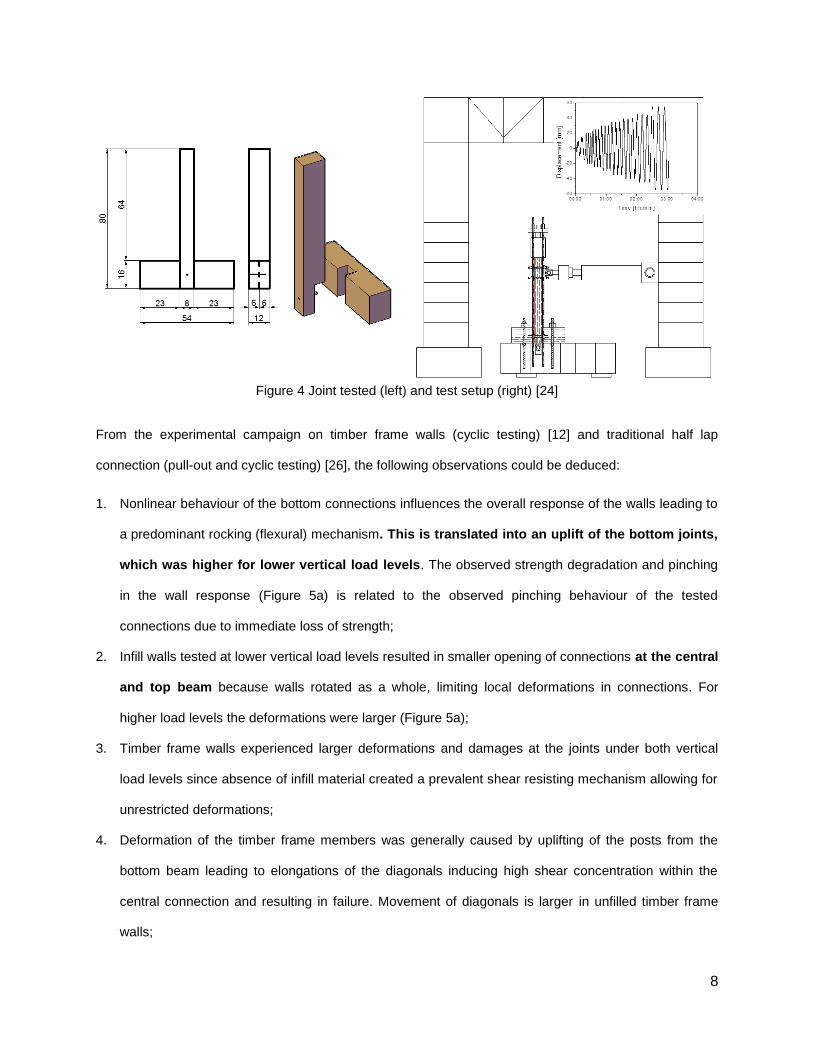
not considered (Figure 4). For the in-plane cyclic tests, two vertical loads were adopted, as done for the
wall tests (Figure 4). From the results, it was apparent the main factors influencing the capacity of the joint
were the presence of gaps and defects in the wood (knots and fissures), as they would constitute
preferential paths for failure [12] as well as the type of strengthening and its ductility.
8
Figure 4 Joint tested (left) and test setup (right) [24]
From the experimental campaign on timber frame walls (cyclic testing) [12] and traditional half lap
connection (pull-out and cyclic testing) [26], the following observations could be deduced:
1. Nonlinear behaviour of the bottom connections influences the overall response of the walls leading to
a predominant rocking (flexural) mechanism. This is translated into an uplift of the bottom joints,
which was higher for lower vertical load levels. The observed strength degradation and pinching
in the wall response (Figure 5a) is related to the observed pinching behaviour of the tested
connections due to immediate loss of strength;
2. Infill walls tested at lower vertical load levels resulted in smaller opening of connections at the central
and top beam because walls rotated as a whole, limiting local deformations in connections. For
higher load levels the deformations were larger (Figure 5a);
3. Timber frame walls experienced larger deformations and damages at the joints under both vertical
load levels since absence of infill material created a prevalent shear resisting mechanism allowing for
unrestricted deformations;
4. Deformation of the timber frame members was generally caused by uplifting of the posts from the
bottom beam leading to elongations of the diagonals inducing high shear concentration within the
central connection and resulting in failure. Movement of diagonals is larger in unfilled timber frame
walls;

9
5. Unloading of the walls is influenced by the difficulty of the post to recover its original position due to
the plastic deformation of the nail;
6. The quality of interlocking in the connections increases the loading capacity of the nail connector.
Out-of-plane opening occurs due to asymmetry in thickness of half-lap connections (Figure 5b);
For a full description of the experimental details and results, see [12] and [26].
(a)
(b)
Figure 5 Experimental results; (a) bottom connection under tensile cyclic loading [24] (URTx =
unreinforced timber joint); (b) timber frame wall [10] (UIWx = unreinforced infill wall with a vertical
pre-compression of xkN/post)
3. Modelling traditional connections
Given that it is intended to develop accurate numerical models that describe adequately the observed
experimental behavior of the timber frame walls, it was decided to divide the work in two phases, namely:
(1) modelling half-lap connections under different loading conditions aiming at deriving the material
parameters controlling the mechanical behavior of the connection; (2) modelling the timber frame walls
under in-plane cyclic loading. The main idea was to calibrate the nonlinear behavior of the bottom
connections from the individual connection tests and then use the material model in the modeling of the
timber frame walls.
The calibration of the tested half-lap connection was performed in OpenSees with a geometric model
representative of the connection and considering similar loading and boundary conditions to the ones
-100 -75 -50 -25 0 25 50 75 100-10
0
10
20
30
40
50
60
70
80
Ve
rtic
al u
plif
t [m
m]
Horizontal displacement [mm]
BR
BL
BM
-120
-80
-40
0
40
80
120
UIW25
UIW50
Lo
ad
[kN
]

10
used in the experimental testing setup (see Figure 6). The response of the tested half-lap connection was
analysed in order to calibrate two-node link elements acting as springs with the appropriate uniaxial
material model to represent the global hysteretic behaviour according to three degrees of freedom,
namely along axial and shear translations and rotation (Figure 6).
Two hysteretic models were used for the calibration of the joints. Pinching4 [23] is a hysteretic
model that represents a 'pinched' load-deformation response and exhibits degradation under
cyclic loading. Strength and stiffness degradation are taken into account considering unloading
stiffness degradation, reloading stiffness degradation and strength degradation (Figure 7a).
Gamma parameters control the cyclic degradation of the model; ratios of force and displacement
(rForce and rDisp) control unloading and reloading points.
The second hysteretic model adopted was SAWS, one-dimensional hysteretic model
developed as part of the CUREe Caltech wood frame project [27]. This model also considers
pinching and strength and stiffness degradation, relating all parameters to the initial stiffness S0
(Figure 7b).
The axial behavior was calibrated through the pull-out tests considering Pinching4 hysteretic available
in Opensees, and the shear and rotational behavior was described based on the SAWS model from in-
plane quasi-static cyclic tests under levels of vertical pre-compression loading equal to 25kN and 50kN.
Figure 6 Schematic of half-lap traditional connection: pull-out (left), in-plane cyclic (right) and the three
behaviours calibrated (1=shear, 2=axial, 3=rotational)

11
(a) (b)
Figure 7 Hysteretic models adopted: (a) Pinching4; (b) SAWS (adapted from [23])
The fitting between experimental results obtained in the pull-out tests and the numerical response of
the connection modeled with N-link elements having non-linear axial behavior (Pinching4 material model)
is shown in Figure 8a. The values obtained for the parameters describing the material model are
presented in Table 1. It is observed that Pinching4 model (Figure 8a) was able to accurately predict the
response obtained in the experimental tests, namely regarding the loading, unloading and re-loading
branches (joint works only axially).
The shear and rotational behavior were calibrated based on the in-plane cyclic tests, during which
the joint is not subjected to axial forces, and assuming one behaviour at a time (see Figure 8b and
c): (1) firstly, the non-linear behaviour was considered to be governed by bending, for which the SAWS
model was adopted for the rotational spring (3 in Figure 6), assuming a linear elastic behaviour in shear
(1 in Figure 6);, (2) secondly, the spring was kept linear in bending (3 in Figure 6) and the SAWS model
was selected to govern the shear behavior of the spring (1 in Figure 6).
Table 1 Calibration of the material laws for springs
Pinching4 parameters for calibration of axial spring
Parameter 1 2 3 4 Limit
pEnvelopeStress (ePfi) 2.33 5.07 4.5 3.00 --
nEnvelopeStress (eNfi) -1.00 -0.90 -0.84 -0.16 --
pEnvelopeStrain (ePdi) 0.0011 0.0295 0.0400 0.0500 --
nEnvelopeStrain (eNdi) -0.0005 -0.0010 -0.0019 -0.0030 --

12
gammaK 0.00 0.00 0.00 0.00 0.00
gammaD 1.00 1.00 1.50 2.00 0.50
gammaF 0.00 0.00 0.00 0.00 0.00
gammaE 10 -- -- -- --
rDisp pos. / neg. 0.8 0.8 -- -- --
rForce pos. / neg. 0.3 0.3 -- -- --
uForce pos. / neg. 0.01 0.01 -- -- --
SAWS parameters for calibration of rotational spring
Parameter 25 kN 50 kN
Intercept strength of shear wall spring element, F0 5.5 7
Intercept strength for spring element pinching branch, FI 0.65 1
Spring element displacement at ult. strength, DU 0.015 0.015
Initial stiffness of shear wall spring element, S0 473 500
Stiffness ratio of the asymptotic line, R1 0.12 0.12
Stiffness ratio of the descending branch, R2 -0.065 -0.09
Stiffness ratio of the unloading branch, R3 2 6
Stiffness ratio of the pinching branch, R4 0.055 0.055
Stiffness degradation parameter for the shear wall spring element, alpha 1.35 1.7
Stiffness degradation parameter for the spring element, beta 1.2 1.2
SAWS parameters for calibration of shear spring
Parameter 25 kN 50 kN
Intercept strength of shear wall spring element, F0 11 11
Intercept strength for spring element pinching branch, FI 0.65 1.4
Spring element displacement at ult. strength, DU 0.01 0.01
Initial stiffness of shear wall spring element, S0 900 1000
Stiffness ratio of the asymptotic line, R1 0.1 0.12
Stiffness ratio of the descending branch, R2 -0.085 -0.09
Stiffness ratio of the unloading branch, R3 2 6
Stiffness ratio of the pinching branch, P4 0.055 0.055
Stiffness degradation parameter for the shear wall spring element, alpha 1.9 1.9
Stiffness degradation parameter for the spring element, beta 1.2 1.2

13
By comparing the experimental and numerical force-displacement diagrams, it is observed that the SAWS
model was able to accurately represent in both cases the envelope and stiffness degradation obtained in
the experimental tests. Therefore, based on the results, Pinching4 model was chosen for the definition of
the axial spring and SAWS model was chosen to describe the behavior of rotational and shear springs.
(a)
(b)
(c) Figure 8 Load-deformation response of the material models for spring calibration: (a) axial spring with
Pinching4 under pull-out; (b) rotational spring with SAWS under 50 kN load; (c) shear spring with SAWS
under 50 kN load
4. Detailed macro-model for timber frame walls without infill
4.1 Detailed macro-model adopted

14
After calibrating the joints individually for each possible behaviour, a 2-D numerical model was
developed for timber frame walls in OpenSees, attributing the non-linearities to the joints
themselves based on the calibrated links. The geometry of the model of the timber frame wall
analyzed is representative of the specimen tested at the Laboratory of Structures at the University of
Minho. Though the cells of the timber-framed wall were not perfectly square (84x86cm) and given
the different width of the elements (16cm bottom and top beam and 8cm middle beam), a
simplification to the member length was assumed to create a square frame consisting of four equal cells
having the dimensions 0.95 x 0.95 m2 for a total height and length of 1.90 m. All members have the same
cross-sectional areas (0.8 x 0.12 m2) except the top and bottom beams (0.16 x 0.12 m
2). The modulus
of elasticity for the timber elements is 11GPa according to experimental testing on the wood species
Pinus pinaster [28].
Horizontal and vertical timber members of the timber frame wallFigure 9 were modelled in Opensees
with beam-column elements adopting a linear constitutive law in OpenSees. The diagonal bracing
members are modelled as truss elements transferring only tensile and compressive forces. An elastic
constitutive law was assumed for the material without shear deformations. Appropriate linear co-
ordinate transformations were applied to transfer local coordinates of the members to global coordinates
of the frame model, which is a mandatory step for Opensees. The base nodes remained fixed,
according to what was observed experimentally, while the global response was controlled by the
calibrated springs.
The global response of the walls was controlled by the springs assigned to the joints. All end
nodes of the members in the frame were duplicated at joints for the insertion of two-node link elements as
springs in order to assign uniaxial material models applied in the corresponding direction of influence. The
central connection was separated into 8 pairs of two-node links. For the 2-D model, three degrees-of-
freedom are considered for the links, namely vertical and horizontal displacements and in-plane rotations.
The two-node elements have zero length and couples the rotations and the translations of connected
nodes sharing the same global coordinates (Figure 9 left).

15
Figure 9 Schematic of the numerical model: two-node link element (left) and frame geometry (centre).
Preliminary analysis showed that the parameters defining uniaxial material model for the spring
obtained from the connection calibration had to be adjusted. High stress concentrations at the base and
in the central connection led to problems of convergence resulting in the loss of nonlinear behaviour. This
issue was solved with additional uniaxial material models, namely elastic no-tension (ENT) and elastic-
perfectly plastic gap (PP gap) material models used in parallel with the calibrated axial spring. ENT
material model was used to have a connection with a high compressive stiffness (as the bottom half-
lap joints had a very different stiffness in compression and in tension) while PP gap material model
enables an initial gap in the connection before loading begins, simulating gaps present in the joints
leading to an absence of immediate response (Figure 10).
Figure 10 Elastic no-tension (left) and elastic-perfectly plastic gap (right) elements [23]
16
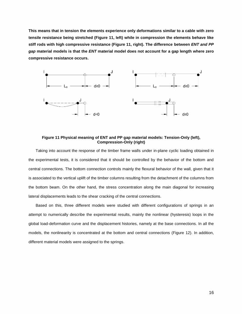
This means that in tension the elements experience only deformations similar to a cable with zero
tensile resistance being stretched (Figure 11, left) while in compression the elements behave like
stiff rods with high compressive resistance (Figure 11, right). The difference between ENT and PP
gap material models is that the ENT material model does not account for a gap length where zero
compressive resistance occurs.
Figure 11 Physical meaning of ENT and PP gap material models: Tension-Only (left), Compression-Only (right)
Taking into account the response of the timber frame walls under in-plane cyclic loading obtained in
the experimental tests, it is considered that it should be controlled by the behavior of the bottom and
central connections. The bottom connection controls mainly the flexural behavior of the wall, given that it
is associated to the vertical uplift of the timber columns resulting from the detachment of the columns from
the bottom beam. On the other hand, the stress concentration along the main diagonal for increasing
lateral displacements leads to the shear cracking of the central connections.
Based on this, three different models were studied with different configurations of springs in an
attempt to numerically describe the experimental results, mainly the nonlinear (hysteresis) loops in the
global load-deformation curve and the displacement histories, namely at the base connections. In all the
models, the nonlinearity is concentrated at the bottom and central connections (Figure 12). In addition,
different material models were assigned to the springs.
17
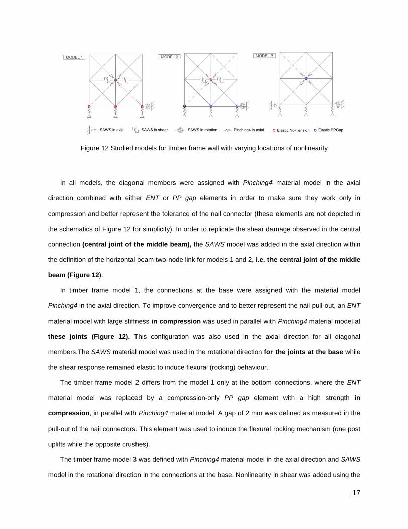
Figure 12 Studied models for timber frame wall with varying locations of nonlinearity
In all models, the diagonal members were assigned with Pinching4 material model in the axial
direction combined with either ENT or PP gap elements in order to make sure they work only in
compression and better represent the tolerance of the nail connector (these elements are not depicted in
the schematics of Figure 12 for simplicity). In order to replicate the shear damage observed in the central
connection (central joint of the middle beam), the SAWS model was added in the axial direction within
the definition of the horizontal beam two-node link for models 1 and 2, i.e. the central joint of the middle
beam (Figure 12).
In timber frame model 1, the connections at the base were assigned with the material model
Pinching4 in the axial direction. To improve convergence and to better represent the nail pull-out, an ENT
material model with large stiffness in compression was used in parallel with Pinching4 material model at
these joints (Figure 12). This configuration was also used in the axial direction for all diagonal
members.The SAWS material model was used in the rotational direction for the joints at the base while
the shear response remained elastic to induce flexural (rocking) behaviour.
The timber frame model 2 differs from the model 1 only at the bottom connections, where the ENT
material model was replaced by a compression-only PP gap element with a high strength in
compression, in parallel with Pinching4 material model. A gap of 2 mm was defined as measured in the
pull-out of the nail connectors. This element was used to induce the flexural rocking mechanism (one post
uplifts while the opposite crushes).
The timber frame model 3 was defined with Pinching4 material model in the axial direction and SAWS
model in the rotational direction in the connections at the base. Nonlinearity in shear was added using the

18
calibrated SAWS model from the individual connections with a larger intercept strength and initial
stiffness of the spring. The Pinching4 model was also used in the axial direction of the diagonal bars
joining at the central connection. In this case, it was decided not to use gap elements in parallel with
Pinching4 model in the base connections. Instead, a larger compression backbone was defined to avoid
crushing of the bottom beam.
The non-linear cyclic analysis was conducted by applying displacement increments of 0.1 mm
with the following displacement cycle-peaks: 15 mm, 30 mm, 40 mm, 50 mm, 60 mm, and 70 mm. The
cyclic analysis was performed only up to 70 mm, even if the experimental tests went up to 90mm with
a softening behaviour. This difference is associated to the early failure of the timber frame wall
without infill and subjected to a vertical pre-compression load of 50kN/post (UTW50) at 70.85 mm
[12]. In the present model it was not possible to capture the failure of the joint. Lateral deformations
were measured at top and mid height of the frame and in addition, the uplift of the bottom left and right
columns from the bottom beams was also recorded. The top lateral displacements was used to derive the
force-displacement hysteresis diagrams.
4.2 Analysis and discussion of the results
The force-displacement diagrams obtained in the numerical modelling using the different timber frame
models are presented in Figure 13. In addition, the comparison between experimental and numerical
vertical displacements (uplift) of the lateral columns as the result of the detachment from the bottom
beams is also provided. The analysis of the results enables to observe that models 2 and 3 are able to
reproduce reasonably well the initial stiffness and maximum lateral strength (monotonic envelop). Lower
performance is atributted to model 1 in achieving this goal, showing a lower stiffness than the ones
obtained in the experimental tests. Increasing the tension backbone of Pinching4 model at the base
connections does not result in the increase of the initial stiffness and overall capacity, but instead results
in higher uplift. The lateral strength obtained in the numerical simulation of the timber frame model 1 is
also lower than the one recorded in the experimental tests. Another difficulty of model 1 is atributted to
the low representativness of the unloading branch. Nevertheless, numerical model 1 is able to reproduce

19
damage (shearing) of the middle beam at the central connection and sliding of diagonal members as it is
shown in the deformed shape of
(d)
Figure 14a, which is in accordance with damages achieved in the experimental testing.
The load-deformation response at the top of the frame is also not very well captured both in model 1
and model 2, given that they are not able to represent the energy dissipation at the central connection.
(a)
(b)

20
(c)
Figure 13 Comparison between experimental results and model output: (a) timber frame model 1; (b) timber frame model 2; (c) timber frame model 3
The numerical model results in terms of force-displacement diagrams and experimental uplifts are only
comparable in the range where experimental data is able to be represented by the model due to the local
collapse of the central beam, which is identified by the sudden drop in the lateral load capacity in the
experimental force-displacement diagrams. Model 2 over-estimates the experimental uplift by 3.4 times
at 59 mm, whereas model 3 underestimates the uplift by approximately 30% at 12 mm compared to the
experimental uplift (Figure 13b,c).
The deformed shape of model 2 (see
(d)
Figure 14b) presents vertical uplift of the vertical columns from the bottom beam and no sliding of the
diagonal. In addition, some noticeable damage in the central connection can be observed through local
displacements.

21
Timber frame model 3 does not replicate neither the sliding of the diagonals nor damage in the
central connection. The resisting mechanism is developed mainly by shear at the base as shown by the
global lateral movement of the frame (
(d)
Figure 14c) but this is not considered to be incompatible with the deformed shape found in the
experimental tests, as no sliding at the base was recorded.
The comparison between experimental and numerical results was complemented with the
comparison between numerical and experimental cumulative energy dissipation, see Figure 14. The
cumulative energy dissipation was calculated from the numerical force-displacement diagrams through
the area of each hysteretic cycle at the maximum displacement in the positive direction, i.e. when the
wall was being pushed (positive displacements in the graph). Notice that some asymmetry on the
experimental response was observed due to features of the test setup during the cyclic loading,
which justifies the possibility of considering only the positive part of the diagrams without losing
accuracy.
Among the numerical models, it is seen that timber frame model 1 presented slightly higher energy
dissipation when compared with timber frame models 2 and 3. However, all models presented lower
energy dissipation than the experimental test. These results indicated that the numerical models present
some weakness in describing the dissipative behavior of the timber frame walls, which is mainly
associated to the deficiencies in describing the stiffness of the unloading branch with the selected
material models for the springs. The main reason is related to the hysteresis loops of model 1, which
are smaller when compared to the others in the unloading branch, the reloading branch is higher,
presenting almost no stiffness and strength dissipation, thus leading to a higher energy
dissipation.
22
(a) (b) (c)
(d)
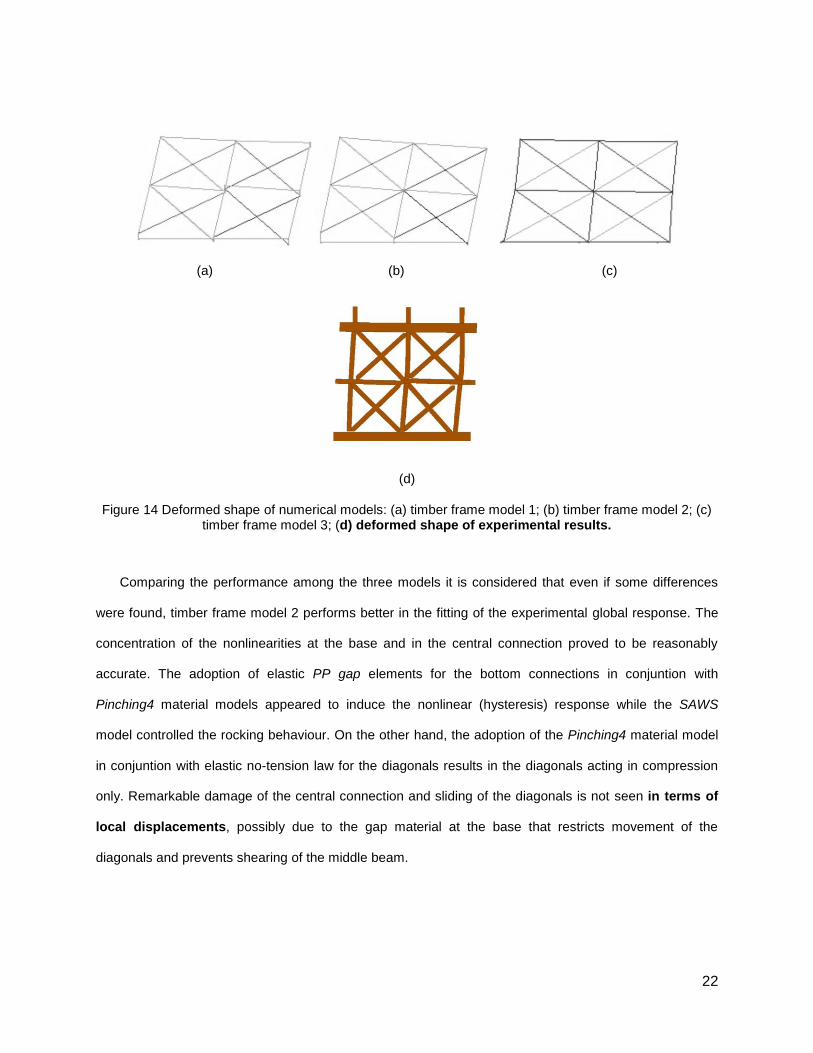
Figure 14 Deformed shape of numerical models: (a) timber frame model 1; (b) timber frame model 2; (c) timber frame model 3; (d) deformed shape of experimental results.
Comparing the performance among the three models it is considered that even if some differences
were found, timber frame model 2 performs better in the fitting of the experimental global response. The
concentration of the nonlinearities at the base and in the central connection proved to be reasonably
accurate. The adoption of elastic PP gap elements for the bottom connections in conjuntion with
Pinching4 material models appeared to induce the nonlinear (hysteresis) response while the SAWS
model controlled the rocking behaviour. On the other hand, the adoption of the Pinching4 material model
in conjuntion with elastic no-tension law for the diagonals results in the diagonals acting in compression
only. Remarkable damage of the central connection and sliding of the diagonals is not seen in terms of
local displacements, possibly due to the gap material at the base that restricts movement of the
diagonals and prevents shearing of the middle beam.

23
Figure 15 Comparison of cumulative energy dissipation between timber frame models
4.3 Simplified calibration of the timber frame with brick infill
Aiming at simulating timber frame walls with brick masonry infills, also tested experimentally, it was
decided to update the timber frame model 2 to include the confining and stiffening effect of masonry infill
in a simplified way, by cancelling nonlinearities in the central connection and only controlling global
response by means of nonlinear connections at the base. From different of experimental results on
frontal walls [12] [16] [17] it was observed that infill was behaving as a block, with minor cracking
in both bricks and mortar joints. In mixed structures, masonry provides a stiffening effect of the
enclosure structure,, impacting the deformation capacity of the joints. This means that a stiffening
of the joints can, in a simplified way, simulate masonry infill. In case of timber frame with brick infill, it
was observed that in-plane cyclic response was mostly governed by flexural behavior much associated to
uplift of the columns resulting from their detachment of the bottom beam and further rocking of the wall.
Stiffness of the diagonal members and of the connections was also increased to 16.5 GPa. The
backbone of the tension side of Pinching4 material model was also updated to better capture the total
load capacity and initial stiffness. The SAWS model used to capture the rotational behavior at the base
connections was adjusted to include the large intercept strength of the spring for the pinching branch.
By comparing the experimental and numerical force-displacement diagrams shown in Figure 16, it is
seen that the model is comparable to the results of timber frame wall with brick infill tested with a vertical

24
pre-compression load of 50kN in each post (UIW50) up to the first failure of the specimen occurring at 70
mm horizontal displacement. After this point, the response of the wall is mostly controlled by the failed
joint, which cannot be acquired by the numerical model. Large asymmetry exists in the experimental
results, which the model is not able to replicate. The model overestimates the uplift by approximately 2.6
times at 66 mm compared to the experimental of 25 mm (Figure 16). This difference may be due to the
concentration of the non-linearities at the base of the wall (therefore the damages). In this
condition, the wall presents a rigid deformation by rotation of the wall around the bottom corners
and the joints of the central beam can be considered mostly rigid. This deformation pattern is
possible due to the detachment of the posts from the bottom beam. The uplift is greater than the one
obtained in timber frame wall without infill, as expected, given the higher predominance of flexural/rocking
behavior. Therefore, the model appears to be able to replicate the predominant rocking mechanism, as is
typical of half-timbered walls with brick masonry infill. No crushing of the middle post at the central
connection is noticeable compared to the experimental damage.
Figure 16 Comparison between experimental and numerical in-plane cyclic response of timber frame with brick infill UIW50
4.4 Analysis of the influence of the aspect ratio of the timber frame
walls

25
A complementary study was conducted after the calibration of the numerical model on the timber
frame with brick infill considering different geometric configurations. Squat and more slender walls were
considered, taking into account the different possibilities that can be found for these walls, see Figure 17.
The influence of the height to length ratio on the lateral response of the wall is analyzed based on the
initial stiffness and lateral load capacity. Additionally, the monotonic lateral load-lateral drift diagrams and
cumulative energy dissipation obtained for the different walls geometry configuration are also presented
and analyzed. The geometric configurations are analysed and compared by imposing a maximum lateral
drift of 10%, while the experimental model reached a maximum drift of around 5%, with increments
on the lateral drifts of 1% (Figure 18a). The values of the lateral load capacity and the lateral initial
stiffness for the different models having different height to length ratio are indicated in Table 2.
The different geometric models were built by assembling different numbers of reference
timber frame cell [1x1] in height and length, aiming at obtaining more squat or slender walls, see
Figure 17.
Models [nx2]
Models [nx1]
Figure 17 Wall configurations studied

26
Squat walls were obtained by having two cells in length (models [1x2], [2x2] and [3x2]) and
slender walls were obtained by adding the reference timber frame cell in height (models [1x1],
[2x1] and [3x1]),
The analysis of the lateral resistance and lateral stiffness indicates that as expected more squat walls
present considerable initial stiffness and higher resistance. The increase on the slenderness induces
lower stiffness and significantly lower lateral resistance.
Table 2 Initial stiffness and load capacity for different configurations of timber frame wall with brick infill
Wall Aspect ratio [H/L] Maximum Load [kN] Initial Stiffness, Kin [kN/mm]
1x2 0.5 340.25 53.13 1x1 1 105.56 16.00 2x2 1 170.12 18.54 3x2 1.5 113.41 8.41
2x1 2 52.78 4.19
3x1 3 35.18 1.70
(a)
(b)
Figure 18 (a) Influence of the height to length ratio on the lateral response of timber frame wall with brick infill; (b) initial stiffness and load capacity
The evolution of the lateral stiffness and resistance with increasing height to length ratios is decreasing,
see Figure 18b. Two different values for load capacity and stiffness are presented for models 1x1
and 2x2 having the same height to length ratio equal to 1. This disparity is due to the difference in
total length of the walls. The analysis of the cumulative dissipated energy for the timber frame walls with
different geometric configuration revealed that more squat walls (nx2, with n varying from 1 to 3,
representing n rows and 2 columns) have considerably higher dissipation than slender walls (nx1, with
n varying from 1 to 3) (Figure 19). These results appear to indicate that the performance of timber frame
walls in masonry buildings is greatly dependent on their geometry.

27
Figure 19 Influence of height to length ratio on cumulative dissipated energy of timber frame wall with
brick infill
6. Conclusions
Timber-framed structures perform as earthquake-resistant construction mostly due to their ability to
dissipate large amounts of energy at connections. From the experimental campaigns on a full-scale
timber frame walls under in-plane cyclic loading, it was evident that they experienced a predominant
rocking (flexural) mechanism with strength degradation and pinching. Energy dissipation is also
concentrated within the central connection (Cross of St. Andrew) due to elongations of diagonals caused
by the lateral loading resulting in shear concentrations within the middle beam.
The identified locations of nonlinearity are used in the development of a detailed numerical model of the
timber frame wall with and without infill based on a macro-modeling approach, being calibrated with
experimental results. A reasonable agreement was found between the experimental and numerical
response of the wall, particularly as concerns the initial stiffness and lateral strength. A good trend in
energy dissipation was also found, even if the models underestimate total cumulative energy dissipated.
The numerical deformation patterns are also compatible with the deformation observed in the
experimental tests, but the uplift is overestimated in the numerical model.
An additional numerical study was developed to analyse the lateral behavior of timber frame walls with
different geometries, namely by varying the height to length ratio. The analysis of the initial stiffness,
lateral load capacity and global load-drift displacement was carried out. It was found that an increasing

28
height to length ratios (slender walls) led to decreasing initial stiffness and lateral strength. On the
contrary, timber frame walls with a decreasing height to length ratio (squat walls) presented greater
energy dissipation. Both lateral load capacity and initial stiffness exhibit an exponential variation with
increasing lateral drift.
These results appear to indicate that the proposed detailedmacro-model approach can be used in the
numerical simulation of traditional timber frame walls. Future developments of this work will concern
the calibration of a simplified macro-model approach with a simplified geometry and non-linearities
concentrated in only one spring for each wall, which would have great advantages when great size
timber frame structures are to be analyzed. With such a model, the modelling of whole buildings can
be carried out with the simplified macro-models to represent internal timber-framed shear walls
and with shell elements to represent the external masonry walls.
Acknowledgments
The research has been supported by the Portuguese Foundation of Science and Technology through
grant SFRH/BPD/99891/2014 and the SAHC Consortium.

29
References
[1] Güçhan N. S. Observations on earthquake resistance of traditional timber-framed houses in
Turkey. Building and Environment 2007; 42: 840–851
[2] Ruggieri N., Tampone G., Zinno R. In-plane vs Out-of-plane “Behaviour” of an Italian Timber
Framed System: the Borbone Constructive System. Historical Analysis and Experimental
Evaluation. International Journal of Architectural Heritage; 2015, 6 Pp. 696-711.
[3] Vintzileou E., Zagkotsis A., Repapis C., Zeris Ch. (2007). Seismic behaviour of the historical
structural system of the island of Lefkada, Greece. Constrion and Building Materials, 21: 225-
236.
[4] Langenbach R. (2007) From “Opus Craticium” to the “Chicago Frame”: Earthquake-Resistant
Traditional Construction. International Journal of Architectural Heritage, 1(1):29-59
[5] Mascarenhas J. Constructive systems – V. Livros Horizonte; 2004, Lisbon,Portugal
[6] Vasconcelos G., Poletti E. Traditional Timber Frame Walls: Mechanical Behavior Analysis
and Retrofitting. In V. P. Panagiotis G. Asteris (Ed.), Handbook of Research on Seismic
Assessment and Rehabilitation of Historic Structures; 2015, pp. 30-59. IGI Global
[7] Tsakanika-Theohari E., Mouzakis H. A post-Byzantine mansion in Athens. Restoration
project of the timber structural elements. In Proceedings of WCTE World Conference on Timber
Engineering, June 20-24, 2010 Riva Del Garda, Trento, Italy.
[8] Torrealva D., Vicente E. Experimental evaluation of seismic behavior of Quincha walls from
the historic centre of Lima – Peru. In Proceedings of 15th World Conference on Earthquake
Engineering (15WCEE), 24-28 September 2012, Lisbon, Portugal.
[9] Quinn N., D’Ayala D., Descamps D. Structural characterisation and Numerical Modelling of
Historic Quincha Walls, International Journal of Architectural Heritage 2015; DOI:
10.1080/15583058.2015.1113337
[10] English Heritage. Practical building conservation. Timber. Ashgate Pulishing Ltd, Farnham,
England, 2012.
[11] Copani P. Timber-frame buildings in Scandinavia: high deformation prevent the system
from collapse. From Material to Structure - Mechanical Behaviour and Failures of the Timber
Structures ICOMOS IWC - XVI International Symposium. Florence, Venice and Vicenza 11-16
November 2007
30
[12] Poletti E., Vasconcelos G. Seismic behaviour of traditional timber frame walls: experimental
results on unreinforced walls. Bulletin of Earthquake Engineering 2015; 13(3): 885-916.
[13] Aktas Y.D., Akyüz U., Türer A., Erdil B., Güçhan N.S. Seismic resistance evaluation of
traditional Ottoman timber-frame Hımıs houses: frame loadings and material tests. Earthquake
Spectra 2013; doi:10.1193/011412EQS011M
[14] Vieux-Champagne, F., Sieffert, Y., Grange, S., Polastri, A., Ceccotti, A., Daudeville, L.
Experimental analysisof seismic resistance of timber-framed structures with stones and earth
infill. Engineering Structures 2014; 69:102–115
[15] Dutu A., Sakata H., Yamazaki Y., Shindo T. In-Plane Behavior of Timber Frames with
Masonry Infills under Static Cyclic Loading. J. Struct. Engrg. Asce 2016; 142(2):
[16] Meireles H., Bento R., Cattari S., Lagomarsino S. A hysteretic model for “frontal” walls in
Pombalino buildings. Bulletin of Earthquake Engineering 2012; 10:1481–1502
[17] Gonçalves, A., Ferreira, J. G., Guerreiro, L., & Branco, F. Experimental characterization of
Pombalino “frontal” Wall cyclic behaviour. In Proceedings of the 15th World Conference on
Earthquake Engineering (15WCEE), 2012.
[18] Kouris L., Kappos A.J. Detailed and simplified non-linear models for timber-framed masonry
structures. Journal of Cultural Heritage 2012; 13(1): 47–58.
[19] Branco J., Descamps T. (2016). Analysis and strengthening of carpentry joints.
Construction and Building Materials, 97: 34-47
[20] Ceccotti A., Sandhaas C. A proposal for a standard procedure procedure to establish the
seismic behaviour factor q of timber buildings. In Proceedings of WCTE World Conference on
Timber Engineering, June 20-24, 2010 Riva Del Garda, Trento, Italy.
[21] Kouris L. A. S., Meireles H., Bento R., Kappos A.J. Simple and complex modelling of
timber-framed masonry walls in Pombalino buildings, Bulletin of Earthquake Engineering 2014;
12: 1777–1803
[22] Casagrande D., Rossi S., Sartori T., Tomasi R. Proposal of an analytical procedure and a
simplified numerical model for elastic response of single-storey timber shear-walls. Construction
and Building Materials 2016; 102: 1101–1112
[23] Mazzoni S., McKenna F., Scott M. H., Fenves G. L. Open System for Earthquake
Engineering Simulation User Command Language Manual. University of California, Pacific
Earthquake Engineering Research Centre, Berkeley, 2006

31
[24] Aranha C., Branco J., Lourenço P., Flatscher G., Schickhofer G. Finite Element Modelling
of the Cyclic Behaviour of CLT Connectors and Walls. WCTE 2016, World Conference on
Timber Engineering. Vienna, Austria.
[25] Schneider J., Shen Y., Stiemer S.F.,Tesfamariam S. Assessment and comparison of
experimental and numerical model studies of cross-laminated timber mechanical connections
under cyclic loading. Construction and Building Materials 2015; 77: 197–212
[26] Poletti E., Vasconcelos G., Branco J.M., Koukouviki A.M. Performance evaluation of
traditional timber joints under cyclic loading and their influence on the seismic response of
timber frame structures. Construction and Building Materials 2016; 127, 321-334
[27] Folz , Filiatrault (2004). Seismic analysis of woodframe structures. I: Model formulation.
Journal of Structural Engineering, 130(9): 1353-1360.
[28] Poletti E. Characterization of the seismic behaviour of traditional timber frame walls.
Universidade do Minho 2013.