numerical modelling of a small mortar dome towards the ... · restoration of a cruzeiro in portugal...
TRANSCRIPT

Structural Analysis of Historical Constructions - Modena, Lourenço & Roca (eds) © 2005 Taylor & Francis Group, London, ISBN 04 1536 379 9
Numerical modelling of a small mortar dome towards the restoration of a cruzeiro in Portugal
P.B. Cachim & A.L. Velosa Department of Civil Engineering, University of Aveiro, Portugal
ABSTRACT: 'Cruzeiros' are a part ofportuguese cultural heritage and should therefore be preserved. Although usually only minor maintenance procedures are necessary, in the specific case described, the 'cruzeiro' had been subject to severe damage and the basis for its reconstruction had to be thoroughly studied. Ali original materiais in good conditions (stone) were maintained but it was necessary to build a new dome; for this severa I mortars were tested taking into account the specific characteristics they must meet. A hydraulic lime mortar was then chosen, guaranteeing compatibility with the existing structure and the dome shape was reformulated in order to reproduce the original dome. A finite element analysis of the whole structure was carried out in order to ensure that the tensile stresses developed during the construction and predicted lifetime ofthe dome were acceptable.
lNTRODUCTION
Intervention in monuments is guided by the principies of the Venice Charter (lCOMOS, 1964), respecting authenticity. In this particular case, a portuguese 'cruzeiro', typical religious construction dessiminated throughout the country with an extremely varied architecture, had been seriously damaged by a car accident. Due to its peculiar configuration, consisting of a small dome built over a cross, it is considered a construction with historic interest and is included in the list of National Monuments.
The damage caused by the accident (Figure I) revealed a dome made from a mixture of cement and coarse sand, possibly an intervention of the 1950s and certainly not the original one, as was later confirmed by ancient photographs. In terms of the remaining structure, most columns remained in a good state, but part of the cross was missing.
In this scenario, and taking into account that the actual dome brought about no additional architectural value and was severely damaged, a decision was made to rebuild the dome in a fashion similar to the original one and to maintain ali original pieces of the monument. Therefore, the architrave and columns were maintained with minor repair resumed to broken zones and the mortar used in ali joints was formulated from the chemical and mineralogical analysis of existing joint mortar.
For the dome itself, an attempt was made to use aesthetically compatible materiais, eliminating Portland cement as a possibility for the binder. Apart
Figure I. State ofthe monument prior to the intervention .
from the lack ofvisual compatibity, this material may introduce soluble salts into the remaining monument, favouring stone decay. The execution of this kind of structure, with a relatively wide span and thickness, in a non-cementitious mortar required a detailed structural analysis and special building procedures.
1.1 Brief historical insight
Cruzeiros are a part of Portuguese religious architecture, usually fulfilling the purpose of creating paths devoted to prayer. The examples found are usually composed by a cross, supported by a pedestal; only in a few cases, this cross has a covering that may be in the form of a dome. Cruzeiro de Sangalhos is included in that category. This type of covering structure seems to
603

be typical ofthe central seaside part ofthe country, as the other similar constructions are found nearby. Built during the 17th century and situated at a crossroad, this structure was the subject of severa I accidents, the last of which brought it down.
2 MATERIALS
The collapse ofthe dome made it possible to verify that it was built with a cement-based mortar (Figure 2), probably during the 20th century with no care for maintenance for monument's originality. With respect to the shape of the dome, it is certain that it is not the original one as can be stated from ancient photographs.
For the intervention, a choice was made to reproduce the original dome in what concerns shape and to use a new lime-based mortar. Although there is no available information about the original materiaIs used to build the dome, this type ofmortar is certainly similar to the original one, as traditionally mortars were composed of lime (more or less hydraulic), sand and other natural materiais, such as clay.
The challenge in the development of this new morta r formulation was to produce a material capable of resisting severe atmospheric conditions with an acceptable structural performance.
2.1 Choice of mortar materiais
In the central seaside region of Portugal, where the 'cruzeiro' was built, construction before the introduction of cement use, was based on the employment of clay. Traditional houses are built of dry clay bricks, called 'adobe ', incorporating more or less lime and local sand and graveI. Similarly, mortars were comoposed of analogous materiais, thus guaranteeing compatibility between these and their support.
However, the performance of lime/clay mortars does not satisfY mechanical requirements for this type
Figure 2. Dome mortar.
of construction and for th is reason, other construction materiais were taken into account.
Natural pozzolanic materiais are widely known and have been used since Roman times. Roman culture spread the use of natural pozzolans, very abundant in many italian regions, and of brick dust, mainly used in non volcanic regions, where no natural pozzolanic material was available. Mortars executed in Roman times containing these materiais have attained high durability and are still in good conditions nowadays, as can be seen in Roman ruins around the world. Furthermore, in recent times both materiaIs have proved themselves to induce an improvement in mortarcharacteristics (Velosa, 2001,2003). Both natural pozzolans (originating from Cape Verde) and brick dust were considered for the new morta r formulation.
In terms ofbinder, dry hydrated lime and hydraulic lime were tested in morta r formulations. The aggregates used in the testing campaign were a coarse yellow sand (Sy) and a fine, previously washed, dune sand of white colour (Sw), both from local provenience.
2.2 Mortar form ulation
Ancient mortars were executed with a wide range of volumetric ratios, depending on the availabity of materiaIs and on local techniques. However the binder/aggregate ratio 1:3 is quite common in our coutry and on this basis, the following mortar formulation were tested:
A testing campaign was executed in order to ascertain the most adequate mortar to use in the dome. The main requirements were a high mechanical strength, low water absorption and a fast carbonation speed. With this aim (see Figure 3), flexural and compressive tests were executed, as well as capillary absorption
Table I. Mortar composi tion.
Hydr. Brick Mortar Lime Lime Dust Pozz.
Ml M2 M3 M4 M5
Figure 3. Carbonation test.
0,5 0,5
Sy Sw
3
3 6
6 6
604
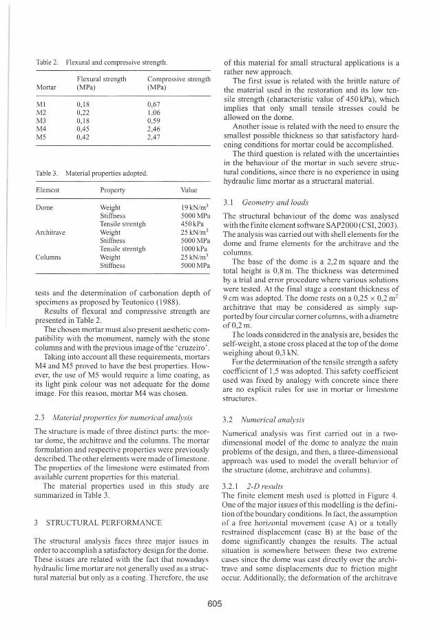
Table 2.
Mortar
MI M2 M3 M4 M5
Table 3.
Element
Dome
Architrave
Columns
Flexural and compressive strength.
Flexural strength (MPa)
0, 18 0,22 0,18 0,45 0,42
Material properties adopted.
Property
Weight Stiffness Tensile strentgh Weight Stiffness Tensile strentgh Weight Stiffness
Compressive strength (MPa)
0,67 1,06 0,59 2,46 2,47
Value
19kN/m3
5000MPa 450 kPa 25 kN/m3
5000MPa 1000kPa 25 kN/m3
5000MPa
tests and the determination of carbonation depth of specimens as proposed by Teutonico (1988).
Results of flexural and compressive strength are presented in Table 2.
The chosen mortar must also present aesthetic compatibility with the monument, namely with the stone columns and with the previous image ofthe 'cruzeiro'.
Taking into account ali these requirements, mortars M4 and M5 proved to have the best properties. However, the use of M5 would require a lime coating, as its light pink colou r was not adequate for the dome image. For this reason, morta r M4 was chosen.
2.3 Material propertiesfor numerical analysis
The structure is made ofthree distinct parts: the mortar dome, the arehitrave and the eolumns. The mortar formulation and respeetive properties were previously described. The other elements were made oflimestone. The properties of the limestone were estimated from available eurrent properties for this material.
The material properties used in this study are summarized in Table 3.
3 STRUCTURAL PERFORMANCE
The struetural analysis faces three major issues in order to aceomplish a satisfaetory design for the dome. These issues are related with the fact that nowadays hydraulic lime mortar are not generally used as a structural material but only as a coating. Therefore, the use
of this material for small structural applications is a rather new approach.
The first issue is related with the brittle nature of the material used in the restoration and its low tensile strength (characteristic value of 450 kPa), which implies that only small tensile stresses could be allowed on the dome.
Another issue is related with the need to ensure the smallest possible thickness so that satisfactory hardening conditions for mortar could be accomplished.
The third question is related with the uncertainties in the behaviour of the mortar in such severe structural eonditions, since there is no experience in using hydraulic lime mortar as a structural material.
3.1 Geometry and loads
The structural behaviour of the dome was analysed with the finite element software SAP2000 (CSr, 2003). The analysis was carried out with shell elements for the dome and frame elements for the architrave and the columns.
The base of the dome is a 2,2 m square and the total height is 0,8 m. The thickness was determined by a trial and error proeedure where various solutions were tested. At the final stage a constant thickness of 9 cm was adopted. The dome rests on a 0,25 x 0,2 m2
architrave that may be considered as simply supported by four circular comer columns, with a diametre ofO,2m.
The loads eonsidered in the analysis are, besides the self-weight, a stone cross placed at the top ofthe dome weighing about 0,3 kN.
For the determination ofthe tensile strength a safety coefficient of 1,5 was adopted. This safety coefficient used was fixed by analogy with concrete since there are no explicit rules for use in morta r or limestone structures.
3.2 Numerical analysis
Numerical analysis was first carried out in a twodimensional model of the dome to analyze the main problems ofthe design, and then, a three-dimensional approach was used to model the overall behavior of the structure (dome, architrave and columns).
3.2.1 2-D results The finite element mesh used is plotted in Figure 4. One ofthe major issues ofthis modelling is the definition ofthe boundary conditions. In fact , the assumption of a free horizontal movement (case A) or a totally restrained displacement (case B) at the base of the dome significantly changes the results. The actual situation is somewhere between these two extreme cases since the dome was cast directly over the arehitrave and some displacements due to friction might oceur. Additionally, the deformation of the arehitrave
605
will also provoke some displacements at the base of the dome.
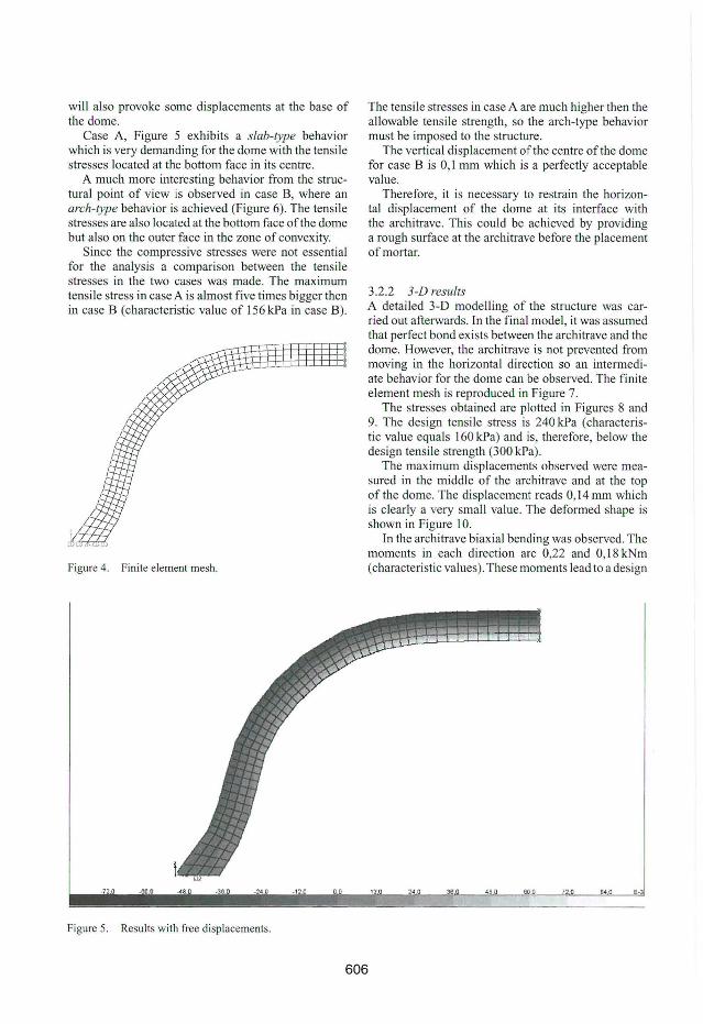
Case A, Figure 5 exhibits a slab-type behavior which is very demanding for the dome with the tensile stresses located at the bottom face in its centre.
A much more interesting behavior from the structural point of view is observed in case B, where an arch-type behavior is achieved (Figure 6). The tensile stresses are also located at the bottom face ofthe dome but also on the outer face in the zone of convexity.
Since the compressive stresses were not essential for the analysis a comparison between the tensile stresses in the two cases was made. The max imum tensile stress in case Ais almost five times bigger then in case B (characteristic value of 156 kPa in case B).
Figure 4. Finite element mesh.
·72 o
Figure 5. Results with free displacements.
The tensile stresses in case A are much higher then the allowable tensile strength, so the arch-type behavior must be imposed to the structure.
The vertical displacement ofthe centre ofthe dome for case B is O, I mm which is a perfectly acceptable value.
Therefore, it is necessary to restrain the horizontal displacement of the dome at its interface with the architrave. This could be achieved by providing a rough surface at the architrave before the placement ofmortar.
3.2.2 3-D results A detailed 3-D modelling of the structure was carried out afterwards. In the final model, it was assumed that perfect bond exists between the architrave and the dome. However, the architrave is not prevented from moving in the horizontal direction so an intermediate behavior for the dome can be observed. The finite element mesh is reproduced in Figure 7.
The stresses obtained are plotted in Figures 8 and 9. The design tensi le stress is 240 kPa (characteristic value equals 160 kPa) and is, therefore, below the design tensile strength (300 kPa).
The maximum displacements observed were measured in the middle of the architrave and at the top of the dome. The displacement reads 0,14 mrn which is clearly a very small value. The deforrned shape is shown in Figure 10.
In the architrave biaxial bending was observed. The moments in each direction are 0,22 and 0, 18 kNm (characteristic values). These moments lead to a design
720 84 0 E-J
606

- 1 .:2 -I'
Figure 6. Results with restrained displacements.
Figure 7. Finite element mesh.
tensile stress of320 kPa which is well below the design tensile strength ofthe limestone.
Therefore, the nurnerical analysis carried out to evaluate the performance ofthe dome indicate that the tensile stresses are sufficiently low in order to avoid
130 -,
Figure 8. Horizontal stresses (bottom face).
cracking. Additionally, the obtained displacements are also very smal!. From a structural point of view it is then possible to build the dome with a hydraulic lime mortar.
The structural behavior of the cruzeiro under horizontalloads (wind and earthquake) were also investigated. The seismic load imposed at the top of the columns, taking into consideration the seismic risk in the central region of Portugal, was 0,1 G (RSA, 1985).
607
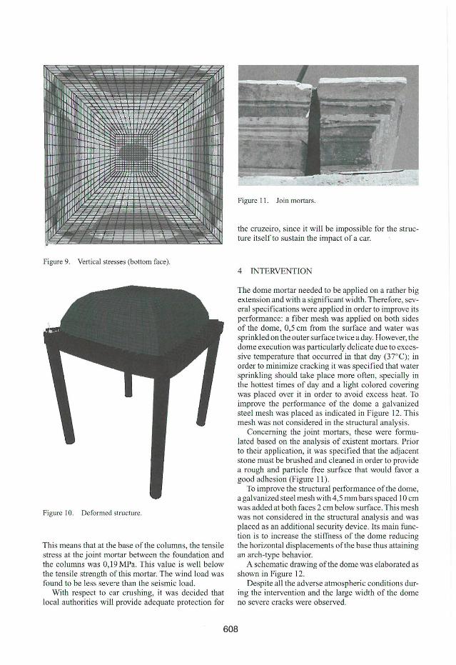
Figure 9. Vertical stresses (bottom face).
Figure 10. Deformed structure.
This means that at the base ofthe columns, the tensile stress at the joint mortar between the foundation and the columns was 0,19 MPa. This value is well below the tensile strength ofthis mortar. The wind load was found to be less severe than the seismic load.
With respect to car crushing, it was decided that local authorities will provide adequate protection for
Figure 11. Join mortars.
the cruzeiro, since it will be impossible for the structure itselfto sustain the impact of a caro
4 INTERVENTION
The dome mortar needed to be applied on a rather big extension and with a significant width. Therefore, several specifications were applied in order to improve its performance: a fiber mesh was applied on both sides of the dome, 0,5 cm from the surface and water was sprinkled on the outer surface twice a day. However, the dome execution was particularly delicate due to excessive temperature that occurred in that day (37°C); in order to minimize cracking it was specified that water sprinkling should take place more often, specially in the hottest times of day and a light colored covering was placed over it in order to avoid excess heat. To improve the performance of the dome a galvanized steel mesh was placed as indicated in Figure 12. This mesh was not considered in the structural analysis.
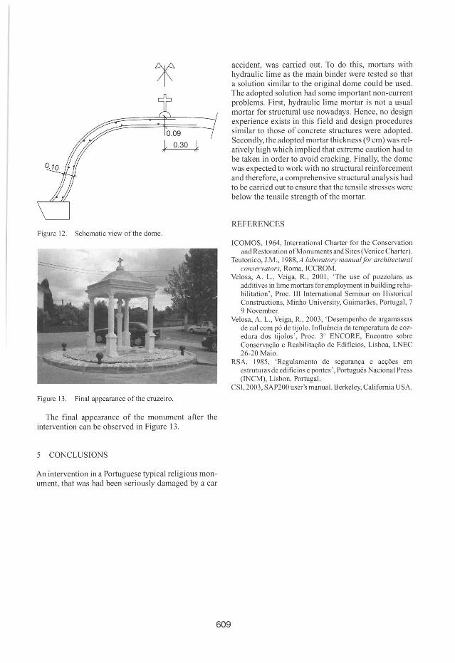
Concerning the joint mortars, these were formulated based on the analysis of existent mortars. Prior to their application, it was specified that the adjacent stone must be brushed and cleaned in order to provide a rough and particle free surface that would favor a good adhesion (Figure 11).
To improve the structural performance ofthe dome, a galvanized steel mesh with 4,5 mm bars spaced 10 cm was added at both faces 2 cm below surface. This mesh was not considered in the structural analysis and was placed as an additional security device. Its ma in nmction is to increase the stiffness of the dome reducing the horizontal displacements ofthe base thus attaining an arch-type behavior.
A schematic drawing ofthe dome was elaborated as shown in Figure 12.
Despite ali the adverse atmospheric conditions during the intervention and the large width of the dome no severe cracks were observed.
608
0.30 L ,
Figure 12. Schematic view ofthe dome.
Figure 13. Final appearance ofthe cruzeiro.
The final appearance of the monument after the intervention can be observed in Figure 13.
5 CONCLUSTONS
An intervention in a Portuguese typical religious monument, that was had been seriously damaged by a ear
609
aeeident, was earried out. To do this, mortars with hydraulie lime as the main binder were tested so that a solution similar to the original dome eould be used. The adopted solution had some important non-eurrent problems. First, hydraulie lime mortar is not a usual morta r for struetural use nowadays. Henee, no design experienee exists in this field and design proeedures similar to those of eonerete struetures were adopted. Seeondly, lhe adopted mortar thiekness (9 em) was relatively high whieh implied lhat extreme eaution had to be taken in order to avoid eraeking. Finally, the dome was expeeted to work with no struetural reinforeement and therefore, a eomprehensive struetural analysis had to be earried out to ensure that the tensile stresses were below the tensile strength ofthe mortar.
REFERENCES
ICOMOS, 1964, International Charter for the Conservation and Restoration ofMonllments and Sites (Venice Charter).
Teutonico, J.M. , 1988, A laboralOlY manualfor archileclural conservalor.\', Roma, ICCROM.
Velosa, A. L. , Veiga, R. , 200 I, 'The use of pozzolans as additives in lime mortars foremployment in building rehabilitation' , Proc. 111 International Seminar on Historical Constrllctions, Minho University, Guimarães, Portugal , 7 9 November.
Velosa, A. L., Veiga, R., 2003, ' Desempenho de argamassas de cal com pó de tijolo. Influência da temperatura de cozedura dos tijolos' , Proc. 3° ENCORE, Encontro sobre Conservação e Reabilitação de Edifícios, Lisboa, LNEC 26-20 Maio.
RSA, 1985, 'Regulamento de segurança e acçôes em estruturas de edifícios e pontes ', Português Nacional Press (INCM), Lisbon, Portugal.
CSI , 2003 , SAP200 user's manual. Berkeley, California USA.