numerical modeling and finite element analysis of … · proceedings of the 4th international...
TRANSCRIPT

Proceedings of the 4th International Conference on Civil Engineering for Sustainable Development (ICCESD 2018), 9~11 February 2018, KUET, Khulna, Bangladesh (ISBN-978-984-34-3502-6)
ICCESD-2018-4887-1
NUMERICAL MODELING AND FINITE ELEMENT ANALYSIS OF SHS COLUMNS RETROFITTED WITH CFRP WRAPPINGS
U. Devi1, M. M. Rahman2, M. F. Rabby3 and M. H. Talukdar4
1 Ph.D. Candidate, North Carolina State University, U.S.A., e-mail: [email protected] 2, 3, 4 Researcher & Structural Engineer, Ahsanullah University of Science and Technology,
Bangladesh, e-mail: [email protected]
ABSTRACT
This paper presents a numerical modeling and finite element analysis on the behavior of steel hollow section (SHS) columns strengthening with Carbon Fibre Reinforced Polymer (CFRP) wrappings, engaging FEA software ABAQUS 6.14-4. A three dimensional finite element model of steel SHS column was developed using both shell and solid element considering both material and geometric nonlinearities whereas CFRP wrappings with different orientations were incorporated in the model with both conventional (S4R) and continuum shell (SC8R) element to capture actual behavior of CFRP retrofitted SHS column. The proposed nuemrical model was then incorporated into the ABAQUS to simulate some of the experimental studies found in relevent literatures. It has been found that good agreement exists between numerical analysis and past experimental results, which has established the acceptability and validity of the proposed finite element model to carry out further investigation. Keywords: Retrofitting, SHS columns, CFRP strips, Finite Element
1. INTRODUCTION
In recent days after experiencing a number of severe earthquakes in Bangladesh and also in nearby country Nepal, people have become more concerned about the rehabilitation of retrofitting of the existing structures. For this reason, the use of Carbon Fiber Reinforced Polymer (CFRP) materials is gaining popularity day by day for repairing of steel structures compared to other conventional retrofitting techniques (Devi and Amanat, 2015; Shaat and Fam, 2006). Since the column is the most important element of the structure, so through retrofitting of columns using CFRP, the whole structure may perform better. In recent years, steel hollow section (SHS) columns have become a great topic of research. Recent research of steel CFRP composite section includes investigating the behavior of axially loaded short and long square hollow structural section (HSS) columns strengthened with carbon fibre reinforced polymer (CFRP) sheets by Shaat and Fam (2006), behavior of steel SHS strengthened with CFRP under large axial deformation by Bambach and Elchalakani (2007), axial capacity and design of thin-walled steel SHS strengthened with CFRP by Bambach MR, et al. (2009), CFRP strengthening of rectangular steel tubes subjected to end bearing loads by Fernando et al. (2009), a numerical finite element investigation on the behavior of steel square hollow structural section (HSS) columns strengthened with CFRP by Devi, U. and Amanat, K.M. (2015). Although such experimental studies provide satisfactory results regarding retrofitting, more research is required in this field. Due to the huge expense of such experiments, numerical studies are being preferred nowadays. This paper focused on developing a three-dimensional finite element model to investigate the behavior and axial strength of SHS columns retrofitted using CFRP wrappings. The proposed model is then used to simulate the experimental results from Bambach and Elchalakani (2007).
2. FINITE ELEMENT METHODOLOGY
In this section, the extensive details of finite element methodology of the experimental study conducted by Bambach and Elchalakani (2007) have been discussed thoroughly. ABAQUS 6.14-4 has been used for numerical modeling. Details of element selection, material modeling boundary conditions and typical results with deflected shapes are included in this section.
4th International Conference on Civil Engineering for Sustainable Development (ICCESD 2018)
ICCESD-2018-4887-2
2.1 Finite Element Modeling
In this study, Finite Element Analysis (FEA) has been carried out using ABAQUS 6.14-4 since this software allows for reducing time, effort, and material costs involved with trial and error manufacturing techniques.
2.2.1 Geometric Properties in Finite Element Model
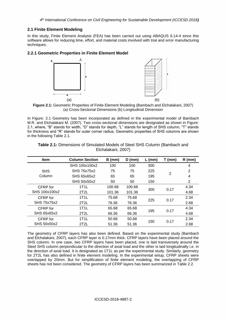
In Figure: 2.1 Geometry has been incorporated as defined in the experimental model of Bambach M.R. and Elchalakani M. (2007). Two cross-sectional dimensions are designated as shown in Figure: 2.1, where, “B” stands for width, “D” stands for depth, “L” stands for length of SHS column, “T” stands for thickness and “R” stands for outer corner radius. Geometric properties of SHS columns are shown in the following Table 2.1.
Table 2.1: Dimensions of Simulated Models of Steel SHS Column (Bambach and Elchalakani, 2007)
Item Column Section B (mm) D (mm) L (mm) T (mm) R (mm)
SHS
Column
SHS 100x100x2 100 100 300
2
4
SHS 75x75x2 75 75 225 2
SHS 65x65x2 65 65 195 4
SHS 50x50x2 50 50 150 2
CFRP for
SHS 100x100x2
1T1L 100.68 100.68 300 0.17
4.34
2T2L 101.36 101.36 4.68
CFRP for
SHS 75x75x2
1T1L 75.68 75.68 225 0.17
2.34
2T2L 76.36 76.36 2.68
CFRP for
SHS 65x65x2
1T1L 65.68 65.68 195 0.17
4.34
2T2L 66.36 66.36 4.68
CFRP for
SHS 50x50x2
1T1L 50.68 50.68 150 0.17
2.34
2T2L 51.36 51.36 2.68
The geometry of CFRP layers has also been defined. Based on the experimental study (Bambach and Elchalakani, 2007), each CFRP layer is 0.17mm thick. CFRP layers have been placed around the SHS column. In one case, two CFRP layers have been placed, one is laid transversely around the Steel SHS column perpendicular to the direction of axial load and the other is laid longitudinally i.e. in the direction of axial load. It is designated as 1T1L as per the experimental study. Similarly, geometry for 2T2L has also defined in finite element modeling. In the experimental setup, CFRP sheets were overlapped by 20mm. But for simplification of finite element modeling, the overlapping of CFRP sheets has not been considered. The geometry of CFRP layers has been summarized in Table 2.2.
(a) (b)
Figure 2.1: Geometric Properties of Finite Element Modeling (Bambach and Elchalakani, 2007) (a) Cross-Sectional Dimensions (b) Longitudinal Dimension

4th International Conference on Civil Engineering for Sustainable Development (ICCESD 2018)
ICCESD-2018-4887-3
Table 2.2: Dimensions of Simulated Models of CFRP Layers (Bambach and Elchalakani, 2007)
Item Designation Orientation B1 (mm) D1 (mm) T (mm) L (mm) R (mm)
CFRP Layers
for
SHS 100x100x2
1T1L Transverse Layer 100.34 100.34
0.17 300 4
1T1L Longitudinal Layer 100.68 100.68
2T2L Transverse Layer 1 100.34 100.34
2T2L Longitudinal Layer 1 100.68 100.68
2T2L Transverse Layer 2 101.02 101.02
2T2L Longitudinal Layer 2 101.36 101.36
CFRP Layers
for
SHS
75x75x2
1T1L Transverse Layer 75.34 75.34
0.17 225 2
1T1L Longitudinal Layer 75.68 75.68
2T2L Transverse Layer 1 75.34 75.34
2T2L Longitudinal Layer 1 75.68 75.68
2T2L Transverse Layer 2 76.02 76.02
2T2L Longitudinal Layer 2 76.36 76.36
CFRP Layers
for
SHS
65x65x2
1T1L Transverse Layer 65.34 65.34
0.17 195 4
1T1L Longitudinal Layer 65.68 65.68
2T2L Transverse Layer 1 65.34 65.34
2T2L Longitudinal Layer 1 65.68 65.68
2T2L Transverse Layer 2 66.02 66.02
2T2L Longitudinal Layer 2 66.36 66.36
CFRP Layers
for
SHS
50x50x2
1T1L Transverse Layer 50.34 50.34
0.17 150 2
1T1L Longitudinal Layer 50.68 50.68
2T2L Transverse Layer 1 50.34 50.34
2T2L Longitudinal Layer 1 50.68 50.68
2T2L Transverse Layer 2 51.02 51.02
2T2L Longitudinal Layer 2 51.36 51.36
2.2.2 Material properties in finite element model
2.2.2.1 Steel SHS Tube
For capturing the actual behavior of SHS column retrofitted with CFRP layers, material properties should be incorporated carefully in finite element modeling. The material property of steel SHS column has been considered as a linear and isotropic material. Young’s and Poisson’s ratio of steel
(a) (b)
Figure 2.2: Stress-Strain Curve for Steel SHS Column from Coupon Test (Bambach and Elchalakani, 2007) (a) for SHS50x50x2, SHS65x65x2 & SHS75x75x2 (b) for SHS 100x100x2

4th International Conference on Civil Engineering for Sustainable Development (ICCESD 2018)
ICCESD-2018-4887-4
SHS column have been taken, except for Steel SHS 100x100x2, 138.285 GPa and 0.3 respectively. Whereas for Steel SHS 100x100x2, Young’s modulus has been taken 200 GPa. The yield stress of SHS column has been taken 350 MPa for all sections, except for SHS section 100x100x2, where yield stress has been taken 450 MPa. The stress-strain curve has been incorporated in Figure 2.2 as per the Coupon test provided by Bambach M.R. and Elchalakani M (2007).
2.2.2.2 CFRP Layers
High strength CFRP materials have been used for retrofitting. In one case, it has been considered linear elastic and isotropic material. In the second case, it has been considered linear elastic and lamina material.
Table 2.1: Material properties of CFRP Layer
Item Young’s Modulus Poisson’s Ratio
CFRP 230 GPA .3
2.2.3 Element selection
Steel SHS column has been modeled using 4-node, quadrilateral, and stress/displacement shell element with reduced integration and large strain formulation which can be found in ABAQUS 6.14-4 as S4R type. In another case, it is also modeled using 8-node linear brick, reduced integration with hourglass control which can be found in ABAQUS 6.14-4 as C3D8R. To capture the actual behavior, CFRP is modeled by using element S4R and SC8R both. The thickness is determined from the element nodal geometry.
2.2.4 Section assignment
For steel SHS sections both homogeneous solid and homogeneous shell sections have been used for modeling. For CFRP sections, homogeneous shell sections and composite shell sections have been incorporated.
2.2.5 Steel-CFRP and CFRP-CFRP interaction
In this finite element modelling, Steel-CFRP and CFRP-CFRP interface have been assumed perfect bonding. For this, tie constraints have been incorporated in the modeling. A tie constraint allows fusing together two regions even though the meshes created on the surfaces of the regions may be dissimilar. A surface-based tie has been adopted. In Steel-CFRP interface, Steel SHS outer surface has been used as master surface whereas, the inner surface of first CFRP layer has been used as slave surface. Again in CFRP-CFRP interface, the outer surface of CFRP layer near SHS column has been considered master surface and the inner surface of CFRP layer far from SHS has been taken as slave surface.
2.2.6 Boundary conditions and loading
2.2.6.1 Boundary Conditions
Boundary condition has been applied as per the experimental study (Bambach M.R. and Elchalakani M., 2007). According to experimental setup ends of the composite SHS were ground square and the CFRP was minimally hand ground at the ends platens of the testing machine. To capture this condition, one end of the steel SHS column has been considered fixed. Also, in one of the case studies, translation in the X and Y –direction has been restrained to avoid the rotation about Z-axis.
2.2.6.2 Load application
Displacement controlled loading has been incorporated into the finite element model. Displacement is applied at the opposite of fixed end at one node in the Z-direction.
2.2.7 Solution strategy
Both the Newton-Raphson method and Arc-Length method have been used for the solution. In this study, it has been seen that the result of Newton-Raphson and Arc-Length method is quite similar. But with Arc-Length method, large range of results can be obtained. So, ultimately study has been conducted using the Arc-Length method only.

4th International Conference on Civil Engineering for Sustainable Development (ICCESD 2018)
ICCESD-2018-4887-5
2.2.8 Figures from finite element modeling
(a) Steel Solid Section (b) CFRP Solid Section (c) Steel-CFRP Shell Section
(d) Close View of CFRP Solid Section
(e) Close View of Steel-CFRP Shell Section
(f) Meshed View of
SHS Column
(g) Boundary Condition (h) Boundary Condition (twisting
restrained)
Figure 2.3: Figures from finite element modeling
3. EXPERIMENTAL MODEL VERIFICATION (BAMBACH AND ELCHALAKANI, 2007)
In this section, the results of the numerical simulations and the tests are compared, and the sensitivity of the models to the key modeling parameters, particularly the imperfection amplitudes, are examined. Comparisons with the test results are made to assess the accuracy of the models and verify their suitability for performing parametric studies.
3.1 Verification of experimental result
Verification was done using the experimental study conducted by M. R. Bambach and M. Elchalakani (2007). SHS 50x50x2, SHS 65x65x2, SHS 75x75x2, SHS 100x100x2 sections taken for verifications. For verifying the proposed models, different combinations of elements and/or modeling techniques have been considered. Tabular representations of verification for section for different case studies are shown in Table: 3.1
Transverse
Layers
Longitudinal Layers
Steel
Displacement
applied along
negative Z
direction
Displacement applied along
negative Z direction
Longitudinal Layers
Transverse
Layers
Twisting restrained
Fixed End Fixed End

4th International Conference on Civil Engineering for Sustainable Development (ICCESD 2018)
ICCESD-2018-4887-6
Table 3.1: Details of Different Case Studies Considered for Verification
Cases Steel SHS CFRP layers
Interaction Element Material Section Element Material Section
Case 1 S4R Elastic,
Isotropic Shell,
Homogenous Not Applicable Not Applicable
Case 2 S4R Elastic,
Isotropic Shell,
Homogenous S4R
Elastic, Isotropic
Shell, Composite
Tie
Case 3 C3D8R Elastic,
Isotropic Solid,
Homogenous SC8R
Elastic, Isotropic
Shell, Composite
Tie
Case 4 S4R Elastic,
Isotropic Shell,
Homogenous SC8R
Elastic, Isotropic
Shell, Composite
Tie
Case 5 S4R Elastic,
Isotropic Shell,
Homogenous S4R
Elastic, Isotropic
Shell, Composite
Tie (with extra DOF for rotation off about z-axis)
Case 6 C3D8R Elastic,
Isotropic Solid,
Homogenous SC8R
Elastic, Isotropic
Shell, Composite
Tie (with extra DOF for rotation off about z-axis)
Case 7 S4R Elastic,
Isotropic Shell,
Homogenous SC8R
Elastic, Isotropic
Shell, Composite
Tie (with extra DOF for rotation off about z-axis)
Parametric key results related to case studies are shown in following figures. Now the graphical representation of verification of experimental studies for various sections and for various combinations is shown in the following Figure: 3.1 - 3.52.
Fig 3.1: SHS 50x50x2 – Case 1
Fig 3.2: SHS 50x50x2 –
Case 2
Fig 3.3: SHS 50x50x2 –
Case 2
Fig 3.4: SHS 50x50x2 –
Case 3

4th International Conference on Civil Engineering for Sustainable Development (ICCESD 2018)
ICCESD-2018-4887-7
Fig 3.5: SHS 50x50x2 –
Case 3
Fig 3.6: SHS 50x50x2 –
Case 4
Fig 3.7: SHS 50x50x2 –
Case 4
Fig 3.8: SHS 50x50x2 –
Case 5
Fig 3.9: SHS 50x50x2 –
Case 5
Fig 3.10: SHS 50x50x2 –
Case 6
Fig 3.11: SHS 50x50x2 –
Case 6
Fig 3.12: SHS 50x50x2 –
Case 7
Fig 3.13: SHS 50x50x2 –
Case 7
Fig 3.14: SHS 65x65x2 –
Case 1 Fig 3.15: SHS 65x65x2 –
Case 2 Fig 3.16: SHS 65x65x2 –
Case 2

4th International Conference on Civil Engineering for Sustainable Development (ICCESD 2018)
ICCESD-2018-4887-8
Fig 3.17: SHS 65x65x2 –
Case 3 Fig 3.18: SHS 65x65x2 –
Case 3 Fig 3.19: SHS 65x65x2 –
Case 4
Fig 3.20: SHS 65x65x2 –
Case 4 Fig 3.21: SHS 65x65x2 –
Case 5 Fig 3.22: SHS 65x65x2 –
Case 5
Fig 3.23: SHS 65x65x2 –
Case 6 Fig 3.24: SHS 65x65x2 –
Case 6 Fig 3.25: SHS 65x65x2 –
Case 7
Fig 3.26: SHS 65x65x2 –
Case 7 Fig 3.27: SHS 75x75x2 –
Case 1 Fig 3.28: SHS 75x75x2 –
Case 2

4th International Conference on Civil Engineering for Sustainable Development (ICCESD 2018)
ICCESD-2018-4887-9
Fig 3.29: SHS 75x75x2 –
Case 2 Fig 3.30: SHS 75x75x2 –
Case 3 Fig 3.31: SHS 75x75x2 –
Case 3
Fig 3.32: SHS 75x75x2 –
Case 4 Fig 3.33: SHS 75x75x2 –
Case 4 Fig 3.34: SHS 75x75x2 –
Case 5
Fig 3.35: SHS 75x75x2 –
Case 5 Fig 3.36: SHS 75x75x2 –
Case 6 Fig 3.37: SHS 75x75x2 –
Case 6
Fig 3.38: SHS 75x75x2 –
Case 7 Fig 3.39: SHS 75x75x2 –
Case 7 Fig 3.40: SHS 100x100x2 –
Case 1

4th International Conference on Civil Engineering for Sustainable Development (ICCESD 2018)
ICCESD-2018-4887-10
Fig 3.41: SHS 100x100x2 –
Case 2 Fig 3.42: SHS 100x100x2 –
Case 2 Fig 3.43: SHS 100x100x2 –
Case 3
Fig 3.44: SHS 100x100x2 –
Case 3 Fig 3.45: SHS 100x100x2 –
Case 4 Fig 3.46: SHS 100x100x2 –
Case 4
Fig 3.47: SHS 100x100x2 –
Case 5 Fig 3.48: SHS 100x100x2 –
Case 5 Fig 3.49: SHS 100x100x2 –
Case 6
Fig 3.50: SHS 100x100x2 –
Case 6 Fig 3.51: SHS 100x100x2 –
Case 7 Fig 3.52: SHS 100x100x2 –
Case 7

4th International Conference on Civil Engineering for Sustainable Development (ICCESD 2018)
ICCESD-2018-4887-11
Tabular representation of verification of maximum experimental load with maximum numerical load is shown in the following Table 3.2
Table 3.2: Comparison between Experimental and Numerical Results
Section Designation Case Experimental
Load (KN) Numerical Load (KN)
Experimental Load/ Numerical Load
50x50x2 Plain Steel Case 1 181.8 133.561 1.361
50x50x2 1T1L
Case 2
201.0
269.257 0.746
Case 3 445.083 0.452
Case 4 292.718 0.687
Case 5 269.222 0.747
Case 6 400.214 0.502
Case 7 290.004 0.693
50x50x2 2T2L
Case 2
213.0
450.573 0.473
Case 3 486.434 0.438
Case 4 556.654 0.383
Case 5 442.789 0.481
Case 6 503.731 0.423
Case 7 498.543 0.427
65x65x2 Plain Steel Case 1 176.6 173.693 1.017
65x65x2 1T1L
Case 2
209.1
283.089 0.739
Case 3 378.734 0.552
Case 4 349.666 0.598
Case 5 281.984 0.742
Case 6 281.861 0.742
Case 7 311.32 0.672
65x65x2 2T2L
Case 2
234.9
467.194 0.503
Case 3 547.274 0.429
Case 4 486.022 0.483
Case 5 464.827 0.505
Case 6 446.615 0.526
Case 7 489.873 0.480
75x75x2 Plain Steel Case 1 198.4 202.797 0.978
75x75x2 1T1L
Case 2
242.7
330.238 0.735
Case 3 719.123 0.337
Case 4 414.979 0.585
Case 5 330.116 0.735
Case 6 674.82 0.360
Case 7 373.919 0.649
75x75x2 2T2L
Case 2
296.5
499.656 0.593
Case 3 830.408 0.357
Case 4 503.528 0.589
Case 5 499.461 0.594
Case 6 813.58 0.364
Case 7 510.667 0.581
100x100x2 Plain Steel Case 1 238.4 347.832 0.685
100x100x2 1T1L
Case 2
354.1
436.204 0.812
Case 3 751.053 0.471
Case 4 397.06 0.892
Case 5 423.979 0.835
Case 6 540.712 0.655
Case 7 389.48 0.909
100x100x2 2T2L
Case 2
480.9
619.093 0.777
Case 3 841.281 0.572
Case 4 545.092 0.882
Case 5 620.663 0.775
Case 6 731.535 0.657
Case 7 536.342 0.897

4th International Conference on Civil Engineering for Sustainable Development (ICCESD 2018)
ICCESD-2018-4887-12
Deflected shape for section SHS 100 x 100 x 2 is shown in Figure: 3.53. From the graphical and tabular representation of verification and the deflection pattern of the simulated SHS sections, it is observed that case 5 shows good agreement with the experimental study. That is, if the Steel SHS is modeled using S4R and CFRP layers are modeled using S4R, then a ratio of more than 0.5 has been achieved between experimental peak load and numerical peak load i.e., there is less deviation from the experimental load. Also by observing the deflection pattern and graphical representation of the of the simulated SHS sections, it is found that case 6 also shows good agreement with the experimental study. That is, if the Steel SHS is modeled using C3D8R and CFRP layers are modeled using SC8R, then a deflected shape similar to the experimental study has been found and. Thus these verified models can be used for further parametric studies of SHS sections retrofitted with CFRP wrapping.
(a) (b) (c)
Figure 3.53: Deflected Shape for Section SHS 100 x 100 x 2 (a) Case 5 - 1T1L (b) Case 6 - 1T1L (c) Case 7 - 1T1L
4. CONCLUSION
In this study, a three-dimensional finite element model to investigate the behavior and axial strength of SHS columns retrofitted using CFRP wrappings has been developed. Finite element analysis has been conducted on the model and the result from this analysis has been verified with the experimental result. In this section, summarization of the findings of the whole finite element analysis is shown.
4.1 Outcomes of the study
Outcomes of the present study are listed below: 1. The experimental study conducted by Bambach and Elchalakani (2007) has been successfully
verified with the 3D finite element model developed using ABAQUS 6.14-4.
2. From the graphical and tabular representation of verification, it is observed that case 5 shows good agreement with the experimental study. That is, if the Steel SHS is modeled using S4R and CFRP layers are modeled using S4R, CFRP material property is defined as elastic isotropic and translation along X-axis & Y-axis is restricted for one node at loading set for avoiding the rotation about Z-axis, then a good agreement has been found between numerical and experimental results. This model can be used for further parametric studies.
3. It has also been found that case 6 shows good agreement with the experimental study in regard to the deflection pattern and graphical representation. That is, if the Steel SHS is modeled using C3D8R and CFRP layers are modeled using SC8R, CFRP material property is defined as elastic isotropic and translation along X-axis & Y-axis is restricted for one node at loading set for avoiding the rotation about Z-axis, then a deflected shape similar to the experimental study has been found. This model can also be used for further parametric studies.
4. In this study, damage property was not assigned to the CFRP materials and the interface between Steel and CFRP has been assumed as perfectly bonded which may have resulted in poor agreements between numerical and experimental study especially in the post-peak regime for many cases.

4th International Conference on Civil Engineering for Sustainable Development (ICCESD 2018)
ICCESD-2018-4887-13
4.2 Future recommendations
1. In this study, damage property of the CFRP material has not been considered. So further study can be conducted incorporating the detailed damage modeling of CFRP materials.
2. In this study, perfect bonding between adjacent two layers has been assumed. In future, cohesive bonding between the layers can be considered to achieve a more accurate result.
3. A parametric study needs to be done by varying different parameters of the proposed finite element model.
REFERENCES
Bambach, M. R. and Elchalakani, M. 2007. “Plastic mechanism analysis of steel SHS strengthened with CFRP under large axial deformation”. Thin-Walled Structures, 45(2), pp. 159-170.
Bambach M. R.; Jama H. H. and Elchalakani M. 2009. “Axial capacity and design of thin-walled steel SHS strengthened with CFRP”. Thin-Walled Structures Volume 47, Issue 10, pages 1112–1121.
Devi U. and Amanat K. M. 2015. “Non-Linear Finite Element Investigation on the Behavior of CFRP Strengthened Steel Square HSS Columns under Compression”. International Journal of Steel Structures, 15(3), p. 671-680.
Fernando D.; Yu T.; Teng J. G. and Zhao X. L. 2009. “CFRP strengthening of rectangular steel tubes subjected to end bearing loads: Effect of adhesive properties and finite element modeling”. Thin-Walled Structures 47, pp. 1020–1028.
Shaat, A. and Fam, A. 2006. “Axial loading tests on short and long hollow structural steel columns retrofitted using carbon fiber reinforced polymers”. Canadian Journal of Civil Engineering, 33(4), pp. 458-470.