numerical investigation of the effects of air/fuel ratio
TRANSCRIPT

FUELS AND COMBUSTION IN ENGINEERING JOURNAL
53
NUMERICAL INVESTIGATION OF THE EFFECTS OF AIR/FUEL RATIO ON COMBUSTION IN A SPARK IGNITION ENGINE
Nureddin DINLER
Gazi University [email protected]
Nuri YUCEL Gazi University
Abstract Combustion is one of the main research areas of internal combustion engines. To reduce the air pollution from internal combustion engines, it is required to increase combustion efficiency. In this study, effects of air/fuel ratio were investigated numerically. An axisymmetrical internal combustion engine was modeled in order to simulate in-cylinder engine flow and combustion. Two dimensional transient continuity, momentum, turbulence, energy and combustion equations were solved. k-ε turbulence model was employed. Fuel mass fraction transport equation was used for modeling of the combustion. For this purpose a computational fluid dynamics code was developed by using finite volume method with using FORTRAN programming code. The moving mesh was utilized to simulate the piston motion. The code developed simulates four strokes of engine continuously. In the case of laminar flow combustion, Arrhenius type combustion equations were employed. In the case of turbulent flow combustion eddy break-up model was employed. Keywords: internal combustion engines, finite volume method, combustion modeling.
1.Introduction
Internal combustion engines are the most widely used machines all over the world. To reduce the air pollutant there are some techniques. One of the prevention techniques is controlling the combustion using air-fuel mixture ratios.
Numerical methods are cheaper than experimental methods and using numerical methods, the parameters, that can not be measured or hard to measure, estimated easily (1). Internal combustion engine modeling is one of the key elements of designing new engines.
Internal combustion engine concept was first designed by Jean de Hautefeuille in 1676 then developed by Huygens and Pupin (2). Then developed by the other researchers and development of internal combustion engines still continues.
Numerous studies could be found in the literature. Researchers studied on combustion using the models in a range of simple thermodynamic models to complicated chemical kinetic models. Few of them are given below.
Abd-Alla (3) studied on spark ignition engine cycle. Abd Alla used thermodynamical model and investigated the effects of compression ratio, equivalence ratio, spark ignition timing, and combustion duration.
El Tahry (4) adopted laminar flamelet model of other researchers’. He compared his computational results with other researchers’ experimental results. There are disparities between results due to assumption of one-dimensional flamelet assumption.
Abu-Orf and Cant (5) developed a new reaction model for premixed turbulent combustion in spark ignition (SI) engines. They compared their engine cylinder pressure with other researchers’ experimental and numerical data. They also investigated the effects of fuel type, equivalence ratio, and engine speed.
Kong and Reitz (6) compared experimental and numerical results of HCCI engine. They used KIVA-3V and CHEMKIN implemented in KIVA-3V. They compared numerical results of cylinder pressure, HC and CO emissions with measured data. According to their calculations numerical model combustion results are not affected with the grid resolution. Coarse mesh and fine mesh structures predicted the combustion with same level of accuracy. The piston-ring crevice needs to be resolved to estimate the emissions. They also concluded the HCCI combustion and emissions are sensitive to initial charge (mixture) temperature and to a lesser extent to the wall temperatures. The CFD model is in good agreement in cylinder pressure, heat release rate and HC emissions. The CO emission was under predicted by the model.
Ogink and Golovitchev (7) studied on gasoline HCCI engine modeling. They combined one dimensional gas dynamics program AVL-BOOST engine cycle simulation code with single-zone combustion model for further engine research. They compared their results with a single cylinder test engine. Their combined code predicts fuel consumption and IMEP over a range of 1-10 % errors.
Soyhan et al. (8) studied chemical mechanism of internal combustion engine. They used automatic construction of the problem-oriented skeleton and reduced mechanisms. The reduction method is based on the simultaneous use of sensitivity, reaction-flow, and lifetime analyses. They used isooctane and n-heptane mixture, they reduced the detailed chemical kinetic mechanism from 74 species, 510 reactions to 19 species, 16 global reactions. They obtained acceptable accuracy.
FUELS AND COMBUSTION IN ENGINEERING JOURNAL
54
In this study, effect of air-fuel ratio on premixed fuel air mixture combustion in an axisymmetrical spark ignition engine cylinder was investigated numerically. In addition to that effect of engine speed on combustion is studied.
2.Problem Definition and Formulation
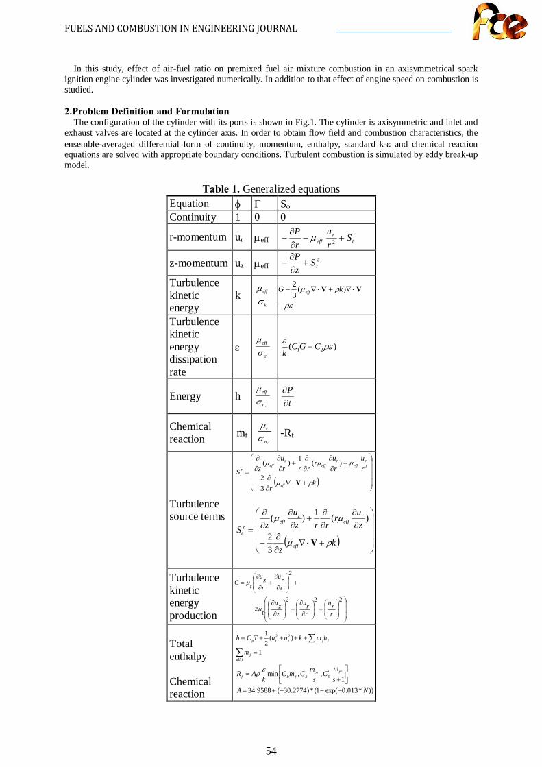
The configuration of the cylinder with its ports is shown in Fig.1. The cylinder is axisymmetric and inlet and exhaust valves are located at the cylinder axis. In order to obtain flow field and combustion characteristics, the ensemble-averaged differential form of continuity, momentum, enthalpy, standard k-ε and chemical reaction equations are solved with appropriate boundary conditions. Turbulent combustion is simulated by eddy break-up model.
Table 1. Generalized equations
Equation φ Γ Sφ Continuity 1 0 0
r-momentum ur µeff rt
reff S
ru
rP
+−∂∂
− 2µ
z-momentum uz µeff ztS
zP
+∂∂
−
Turbulence kinetic energy
k k
eff
σµ
ρε
ρµ
−
⋅∇+⋅∇− VV )(32 kG eff
Turbulence kinetic energy dissipation rate
ε εσ
µeff )( 21 ρεε CGCk
−
Energy h tn
eff
,σµ
tP
∂∂
Chemical reaction mf
tn
t
,σµ -Rf
Turbulence source terms
( )
+⋅∇∂∂
−
−∂∂
∂∂
+∂∂
∂∂
=k
r
ru
ru
rrrr
uzS
eff
reff
reff
zeff
rt
ρµ
µµµ
V32
)(1
)( 2
( )
+⋅∇∂∂
−
∂∂
∂∂
+∂∂
∂∂
=k
z
zur
rrzu
zS
eff
reff
zeff
zt
ρµ
µµ
V32
)(1)(
Turbulence kinetic energy production
+
∂
∂+
∂
∂
+
∂
∂+
∂
∂=
2222
2
rru
rru
zzu
t
zru
rzu
tG
µ
µ
Total enthalpy Chemical reaction
∑∑
=
++++=
jallj
jjzrp
m
hmkuuTCh
1
)(21 22
))*013.0exp(1(*)2774.30(9588.341
,,min
NAsm
Cs
mCmCk
AR prR
oxRfRf
−−−+=
+
′=ερ
FUELS AND COMBUSTION IN ENGINEERING JOURNAL
55
on the solid surface
source term
Effective viscosity µµµ += teff Turbulent viscosity ερµ µ /2kCt =
zu
rru
rzr
∂∂
+∂
∂=⋅∇
)(1V
Fig. 1: Schematically description of piston-cylinder assembly of the problem. The equations were given in a form of general transport equation type. For a general φ dependent variable,
independent variables and source terms were given in Table 1 (9, 10).
φ
φφφρφρφρ Sr
rrrzzr
urrz
ut
rz +∂∂
Γ∂∂
+∂∂
Γ∂∂
=∂
∂+
∂∂
+∂
∂ )(1)()(1)()(
Γ : Diffusion coefficient of φ variable Sφ : Source term for φ variable
Turbulence model constants were chosen C1 = 1.44, C2 = 1.92, Cµ = 0.09 , σk = 1.00, σε = 1.30. Wall functions that are applied to near wall flow are given in detail in Versteeg and Malalasekera (9). Equation of state: P = ρRT Boundary and initial conditions that used in order to solve the equations are given below.
At the cylinder head (z = 0) (during the intake) uz = uz-in ur = ur-in T = Tin= 300 K 20001,0
inzin uk = mf=0.055
)035.0/(1643.0 5,1 Bkinin =ε uz = 0, ur = 0, k=0, ε=0,
T = 450 K, 0=∂
∂z
m f
On the piston face (z = zpiston)
u
uu
r-in
inz-in
z
r
rr
id
R
z (t)pis
u (t)pis
at the valve inlet

FUELS AND COMBUSTION IN ENGINEERING JOURNAL
56
uz = Upis(t), ur = 0, k=0, ε=0 T = Tpis=450K, 0=∂
∂z
m f
On the cylinder surface (r = R)
uz = 0, ur = 0, k=0, ε=0,T = 450 K, 0=∂
∂
rm f
At the symmetry axis (r = 0)
0,0 ==∂∂
rz u
ru
0,0,0,0 =∂
∂=
∂∂
=∂∂
=∂∂
rm
rT
rrk fε
Initial conditions (t=0) uz = 0, ur = 0, k = 0, ε = 0, T =Tinitial= 300 K mf=0.0
Reciprocating motion of piston is modeled by using moving mesh technique. All equations were converted according to conversion equation of moving mesh (11, 12).
)(tzz
pis=ξ
3. Numerical Solution Procedure
The governing equations subject to relevant boundary conditions were solved numerically using finite-volume method. The upwind technique was employed to discretize the convective terms. All discretization steps were given in (13). A computational fluid dynamics code has been developed by using the SIMPLE (10) algorithm. In order to obtain a solution independent of the grid distribution, grid sensitivity tests were performed by tracing the cylinder pressure against crank angle as it was done by Watkins et al. (14). It is found that the solution becomes almost independent with 50 uniform grids in ξ direction and 30 uniform grids in the r-direction. All momentum, energy and chemical reaction equations are coupled and all are solved together.
4. Results and Discussion
In this study combustion in an idealized homogeneous charge spark ignition engine are analyzed numerically. It is assumed that spark plug and inlet/exhaust valves are located at the centerline of cylinder. Computations are performed for three different air fuel ratios, compression ratio r=10:1 and inlet valve angle 60o. Engine speed is set to N=24 rpm and N=2400 rpm, which are correspond to laminar and turbulent flow conditions, respectively. Cylinder bore D=0.1 m, stroke L=0.09 m and diameter of inlet/exhaust valve d=0.05 m are chosen. Methane (CH4) is used as a fuel. In the case of laminar flow combustion, Arrhenius type combustion equations were employed. In the case of turbulent flow combustion eddy break-up model was employed.
Ignition timing is an important parameter for spark ignition engine combustion. Ignition timing advance, (IT) is calculated by the following equation which is suggested by the authors.
))00087.0exp(1(282.1283635.6 NIT −−+=
Combustion is started assuming the 70 percent of fuel consumed at the ignition time in the region around the spark plug. This region corresponds to the computation cells of (1 to 3 X 1 to 10) (r X ξ). The flame develops from the ignition points in a nearly hemispherical region and it reaches to the piston surface. Then the flame front propagates in the radial direction.
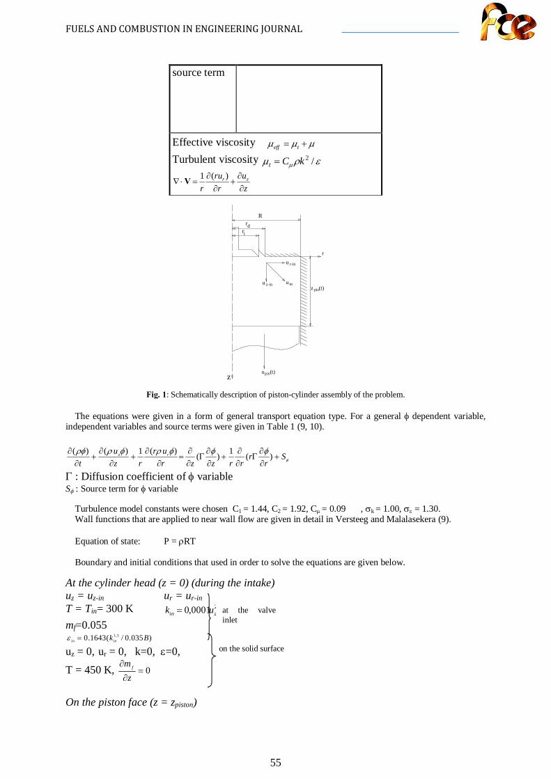
To simulate the air-fuel mixture compositions, excess air coefficient λ was chosen λ=0.9, 1.0, 1.1 represents the mixtures of rich, stoichiometric and lean, respectively. Air fuel mixture enters the cylinder with given values as boundary condition, then concentration of fuel changes in the cylinder. During the intake stroke, contours of mass fraction of fuel look similar but have different values due to mixture composition. After piston reaches BDC, valve opening closes and the air–fuel mixture compressed during the compression stroke and homogeneous mixture fraction obtained (Fig 2). After the ignition, the flame develops from the ignition points in a nearly hemispherical region and it reaches to the piston surface. Then the flame front propagates in the radial direction. For the rich and stoichiometric mixtures combustion duration is the same because the maximum
FUELS AND COMBUSTION IN ENGINEERING JOURNAL
57
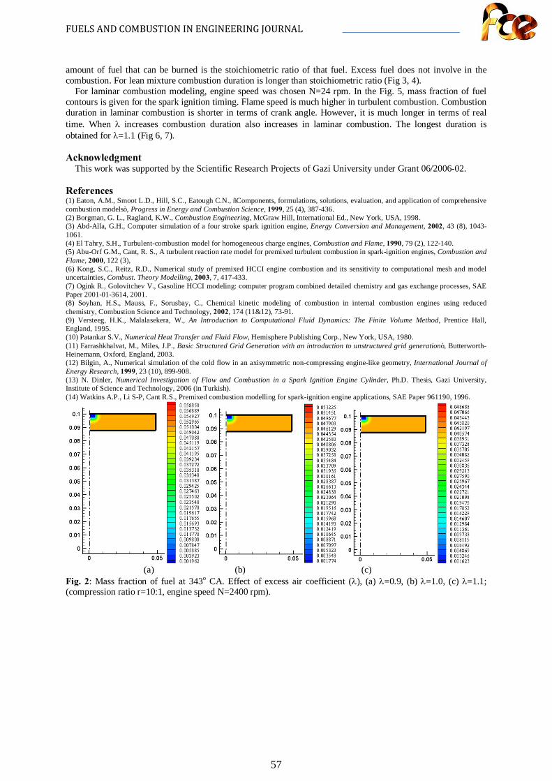
amount of fuel that can be burned is the stoichiometric ratio of that fuel. Excess fuel does not involve in the combustion. For lean mixture combustion duration is longer than stoichiometric ratio (Fig 3, 4).
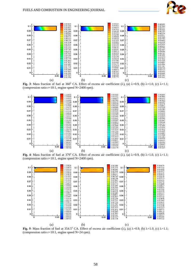
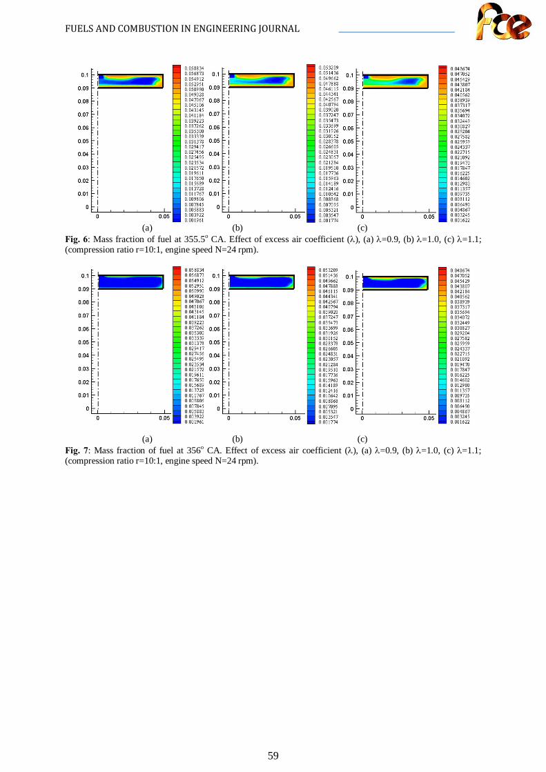
For laminar combustion modeling, engine speed was chosen N=24 rpm. In the Fig. 5, mass fraction of fuel contours is given for the spark ignition timing. Flame speed is much higher in turbulent combustion. Combustion duration in laminar combustion is shorter in terms of crank angle. However, it is much longer in terms of real time. When λ increases combustion duration also increases in laminar combustion. The longest duration is obtained for λ=1.1 (Fig 6, 7).
Acknowledgment
This work was supported by the Scientific Research Projects of Gazi University under Grant 06/2006-02.
References (1) Eaton, A.M., Smoot L.D., Hill, S.C., Eatough C.N., “Components, formulations, solutions, evaluation, and application of comprehensive combustion models”, Progress in Energy and Combustion Science, 1999, 25 (4), 387-436. (2) Borgman, G. L., Ragland, K.W., Combustion Engineering, McGraw Hill, International Ed., New York, USA, 1998. (3) Abd-Alla, G.H., Computer simulation of a four stroke spark ignition engine, Energy Conversion and Management, 2002, 43 (8), 1043-1061. (4) El Tahry, S.H., Turbulent-combustion model for homogeneous charge engines, Combustion and Flame, 1990, 79 (2), 122-140. (5) Abu-Orf G.M., Cant, R. S., A turbulent reaction rate model for premixed turbulent combustion in spark-ignition engines, Combustion and Flame, 2000, 122 (3), (6) Kong, S.C., Reitz, R.D., Numerical study of premixed HCCI engine combustion and its sensitivity to computational mesh and model uncertainties, Combust. Theory Modelling, 2003, 7, 417-433. (7) Ogink R., Golovitchev V., Gasoline HCCI modeling: computer program combined detailed chemistry and gas exchange processes, SAE Paper 2001-01-3614, 2001. (8) Soyhan, H.S., Mauss, F., Sorusbay, C., Chemical kinetic modeling of combustion in internal combustion engines using reduced chemistry, Combustion Science and Technology, 2002, 174 (11&12), 73-91. (9) Versteeg, H.K., Malalasekera, W., An Introduction to Computational Fluid Dynamics: The Finite Volume Method, Prentice Hall, England, 1995. (10) Patankar S.V., Numerical Heat Transfer and Fluid Flow, Hemisphere Publishing Corp., New York, USA, 1980. (11) Farrashkhalvat, M., Miles, J.P., Basic Structured Grid Generation with an introduction to unstructured grid generation”, Butterworth-Heinemann, Oxford, England, 2003. (12) Bilgin, A., Numerical simulation of the cold flow in an axisymmetric non-compressing engine-like geometry, International Journal of Energy Research, 1999, 23 (10), 899-908. (13) N. Dinler, Numerical Investigation of Flow and Combustion in a Spark Ignition Engine Cylinder, Ph.D. Thesis, Gazi University, Institute of Science and Technology, 2006 (in Turkish). (14) Watkins A.P., Li S-P, Cant R.S., Premixed combustion modelling for spark-ignition engine applications, SAE Paper 961190, 1996.
(a) (b) (c)
Fig. 2: Mass fraction of fuel at 343o CA. Effect of excess air coefficient (λ), (a) λ=0.9, (b) λ=1.0, (c) λ=1.1; (compression ratio r=10:1, engine speed N=2400 rpm).
FUELS AND COMBUSTION IN ENGINEERING JOURNAL
58
(a) (b) (c)
Fig. 3: Mass fraction of fuel at 360o CA. Effect of excess air coefficient (λ), (a) λ=0.9, (b) λ=1.0, (c) λ=1.1; (compression ratio r=10:1, engine speed N=2400 rpm).
(a) (b) (c)
Fig. 4: Mass fraction of fuel at 379o CA. Effect of excess air coefficient (λ), (a) λ=0.9, (b) λ=1.0, (c) λ=1.1; (compression ratio r=10:1, engine speed N=2400 rpm).
(a) (b) (c) Fig. 5: Mass fraction of fuel at 354.5o CA. Effect of excess air coefficient (λ), (a) λ=0.9, (b) λ=1.0, (c) λ=1.1; (compression ratio r=10:1, engine speed N=24 rpm).
FUELS AND COMBUSTION IN ENGINEERING JOURNAL
59
(a) (b) (c)
Fig. 6: Mass fraction of fuel at 355.5o CA. Effect of excess air coefficient (λ), (a) λ=0.9, (b) λ=1.0, (c) λ=1.1; (compression ratio r=10:1, engine speed N=24 rpm).
(a) (b) (c) Fig. 7: Mass fraction of fuel at 356o CA. Effect of excess air coefficient (λ), (a) λ=0.9, (b) λ=1.0, (c) λ=1.1; (compression ratio r=10:1, engine speed N=24 rpm).