numerical control infrastructureyvonet.florent.free.fr/serveur/cours catia/catia...1.17 - define 3...
TRANSCRIPT
CATIA Training
COPYRIGHT DASSAULT SYSTEMES Version 5 Release 19 January 2009 EDU-CAT-EN-NCI-FS-V5R19
NNuummeerriiccaall CCoonnttrrooll IInnffrraassttrruuccttuurree
DDeettaaiilleedd SStteeppss
Numerical Control Infrastructure Detailed Steps
COPYRIGHT DASSAULT SYSTEMES 2
TTaabbllee ooff CCoonntteennttss Master Exercise: Aerospace Structure Part............................................................................................ 3
Step 1: CATProcess Presentation....................................................................................................... 3 Step 2A: Machining Operation Presentation ...................................................................................... 8 Step 2B: Replay and Material Removal Simulation .......................................................................... 15 Step 3A: Create Auxiliary Operations................................................................................................ 20 Step 3B: Create Spot drilling and Drilling Operations ....................................................................... 27 Step 4: Generate Outputs.................................................................................................................. 35
Advanced Exercises.............................................................................................................................. 41 AdvEX 00: Import APT File and Modify Tool Path ............................................................................ 41 AdvEX 01: Import V4 Model .............................................................................................................. 45 AdvEX 02: Create a Machining Process and Instantiate It in the Current Model from Catalog........ 51 AdvEX 03: Manage Resources ......................................................................................................... 63 AdvEX 04: Auto Complete................................................................................................................. 71 AdvEX 05: PPWords Table Customization ....................................................................................... 75 AdvEX 06: Design Change................................................................................................................ 81
Numerical Control Infrastructure Detailed Steps
COPYRIGHT DASSAULT SYSTEMES 3
Master Exercise: Aerospace Structure Part
Step 1: CATProcess Presentation
1.1 - Open the product to machine
Menu File, Open Start_Step1_CATProcessPresentation_SetupDefinition.CATProduct
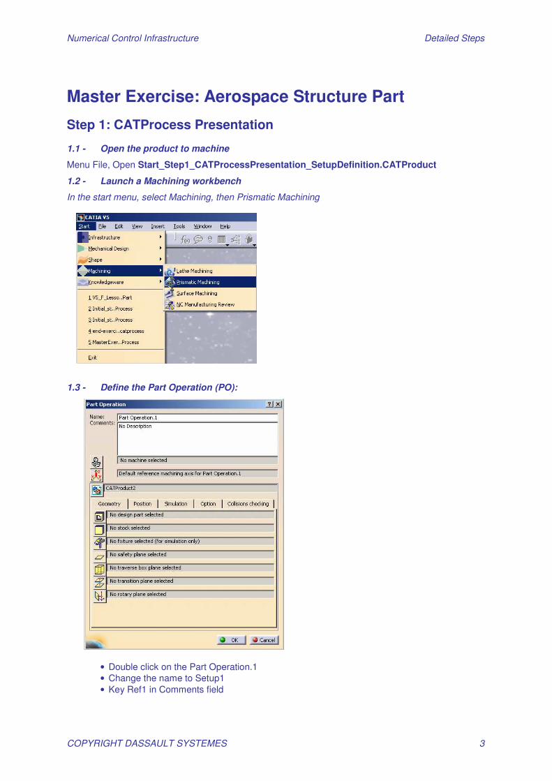
1.2 - Launch a Machining workbench
In the start menu, select Machining, then Prismatic Machining
1.3 - Define the Part Operation (PO):
• Double click on the Part Operation.1 • Change the name to Setup1 • Key Ref1 in Comments field
Numerical Control Infrastructure Detailed Steps
COPYRIGHT DASSAULT SYSTEMES 4
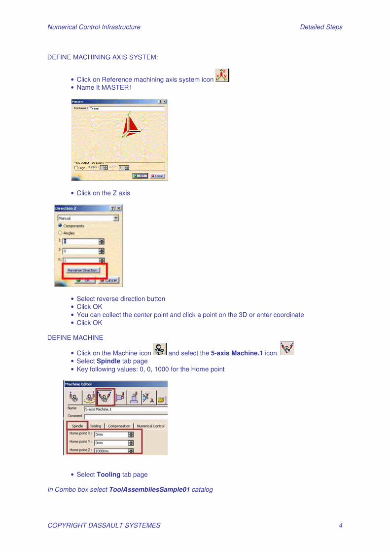
DEFINE MACHINING AXIS SYSTEM:
• Click on Reference machining axis system icon • Name It MASTER1
• Click on the Z axis
• Select reverse direction button • Click OK • You can collect the center point and click a point on the 3D or enter coordinate • Click OK
DEFINE MACHINE
• Click on the Machine icon and select the 5-axis Machine.1 icon. • Select Spindle tab page • Key following values: 0, 0, 1000 for the Home point
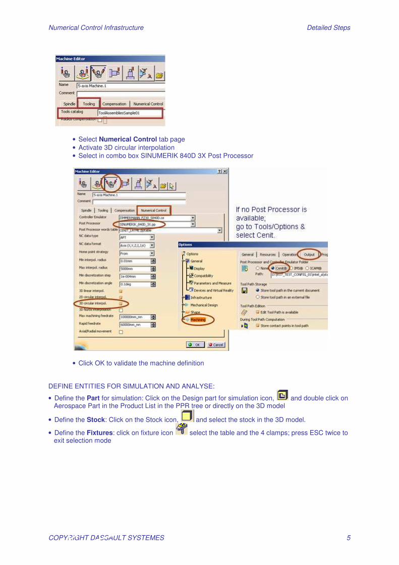
• Select Tooling tab page In Combo box select ToolAssembliesSample01 catalog
Numerical Control Infrastructure Detailed Steps
COPYRIGHT DASSAULT SYSTEMES 5
• Select Numerical Control tab page • Activate 3D circular interpolation • Select in combo box SINUMERIK 840D 3X Post Processor
• Click OK to validate the machine definition DEFINE ENTITIES FOR SIMULATION AND ANALYSE:
• Define the Part for simulation: Click on the Design part for simulation icon, and double click on Aerospace Part in the Product List in the PPR tree or directly on the 3D model
• Define the Stock: Click on the Stock icon, and select the stock in the 3D model.
• Define the Fixtures: click on fixture icon select the table and the 4 clamps; press ESC twice to exit selection mode
Numerical Control Infrastructure Detailed Steps
COPYRIGHT DASSAULT SYSTEMES 6
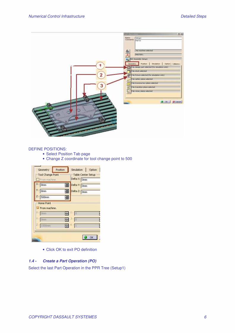
DEFINE POSITIONS:
• Select Position Tab page • Change Z coordinate for tool change point to 500
• Click OK to exit PO definition
1.4 - Create a Part Operation (PO)
Select the last Part Operation in the PPR Tree (Setup1)
Numerical Control Infrastructure Detailed Steps
COPYRIGHT DASSAULT SYSTEMES 7
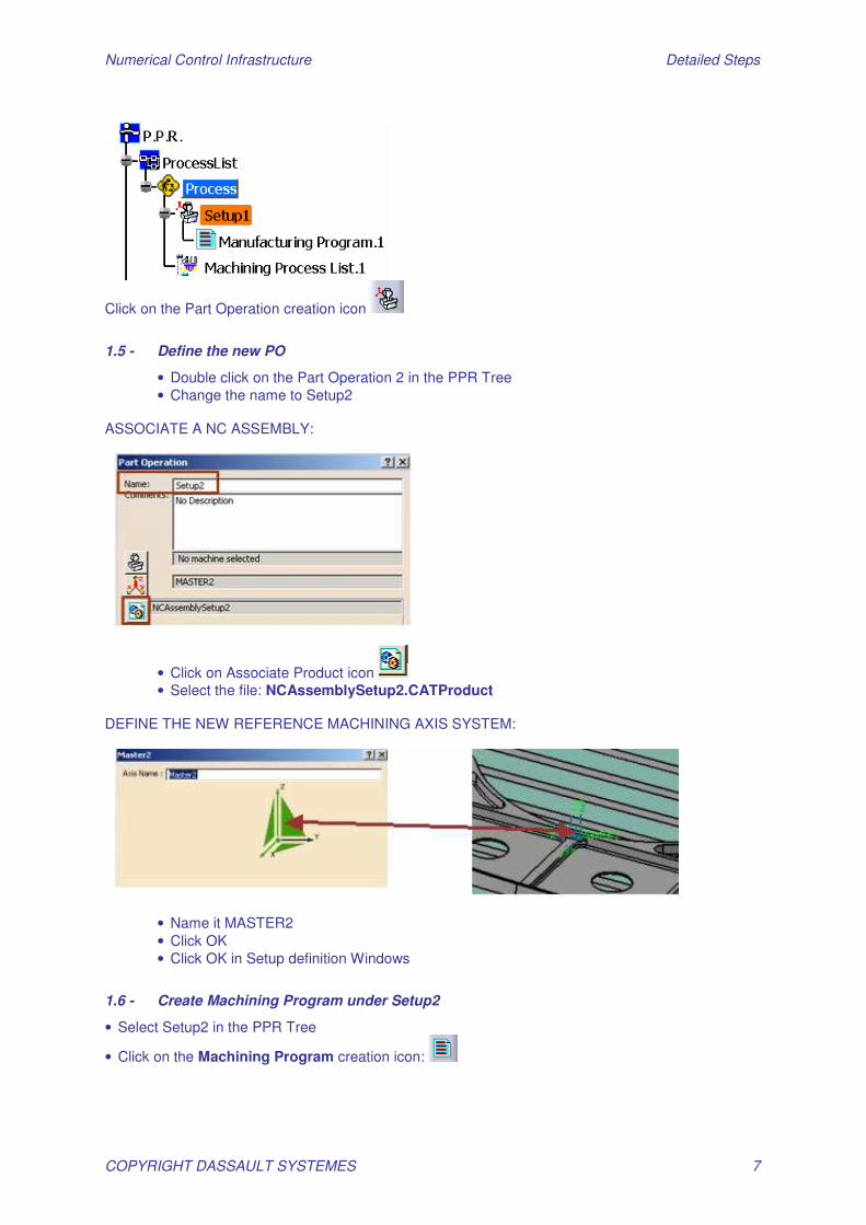
Click on the Part Operation creation icon
1.5 - Define the new PO
• Double click on the Part Operation 2 in the PPR Tree • Change the name to Setup2
ASSOCIATE A NC ASSEMBLY:
• Click on Associate Product icon • Select the file: NCAssemblySetup2.CATProduct
DEFINE THE NEW REFERENCE MACHINING AXIS SYSTEM:
• Name it MASTER2 • Click OK • Click OK in Setup definition Windows
1.6 - Create Machining Program under Setup2
• Select Setup2 in the PPR Tree
• Click on the Machining Program creation icon:
Numerical Control Infrastructure Detailed Steps
COPYRIGHT DASSAULT SYSTEMES 8
Step 2A: Machining Operation Presentation Open Start_Step2A_MachiningOpnPresentation.CATProcess
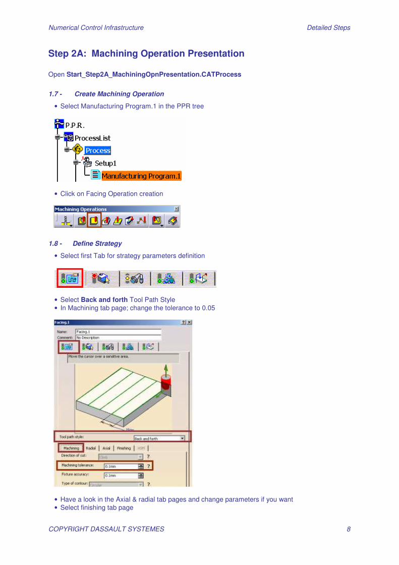
1.7 - Create Machining Operation
• Select Manufacturing Program.1 in the PPR tree
• Click on Facing Operation creation
1.8 - Define Strategy
• Select first Tab for strategy parameters definition
• Select Back and forth Tool Path Style • In Machining tab page; change the tolerance to 0.05
• Have a look in the Axial & radial tab pages and change parameters if you want • Select finishing tab page
Numerical Control Infrastructure Detailed Steps
COPYRIGHT DASSAULT SYSTEMES 9
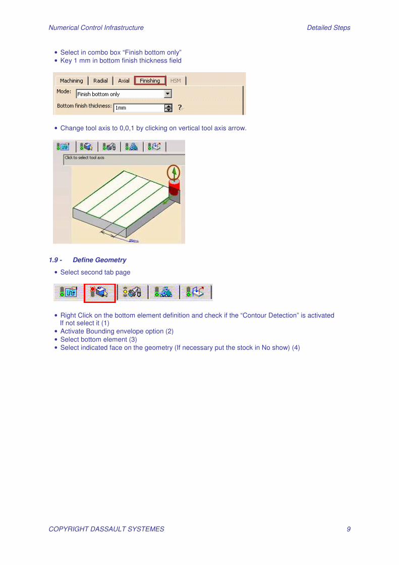
• Select in combo box “Finish bottom only” • Key 1 mm in bottom finish thickness field
• Change tool axis to 0,0,1 by clicking on vertical tool axis arrow.
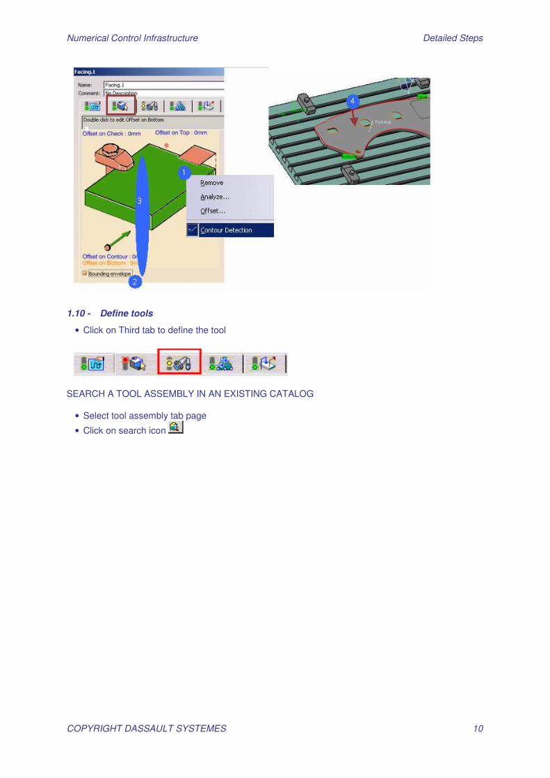
1.9 - Define Geometry
• Select second tab page
• Right Click on the bottom element definition and check if the “Contour Detection” is activated If not select it (1) • Activate Bounding envelope option (2) • Select bottom element (3) • Select indicated face on the geometry (If necessary put the stock in No show) (4)
Numerical Control Infrastructure Detailed Steps
COPYRIGHT DASSAULT SYSTEMES 10
1.10 - Define tools
• Click on Third tab to define the tool
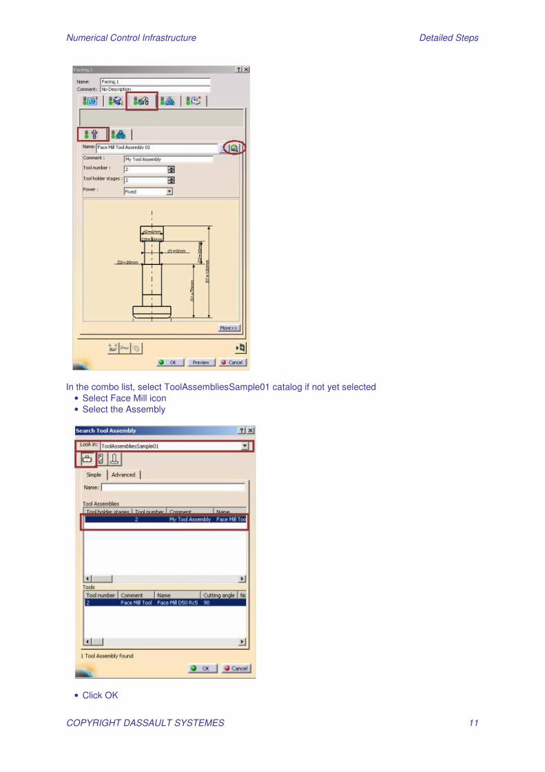
SEARCH A TOOL ASSEMBLY IN AN EXISTING CATALOG
• Select tool assembly tab page
• Click on search icon
Numerical Control Infrastructure Detailed Steps
COPYRIGHT DASSAULT SYSTEMES 11
In the combo list, select ToolAssembliesSample01 catalog if not yet selected
• Select Face Mill icon • Select the Assembly
• Click OK

Numerical Control Infrastructure Detailed Steps
COPYRIGHT DASSAULT SYSTEMES 12
1.11 - Define Machine Feeds & Speeds
Select 4th tab page
The feeds and speeds are computed according to the values of the tool you have defined previously
• Unselect the automatic computation • Enter 3000 for the four feedrates (Approach; Retract; Finishing; Machining) • Select linear unit in first combo list • Enter 5000 for spindle speed • Select Angular in second combo list
1.12 - Define Macro Motions
• Click on Last tab to define Approach and retract macro
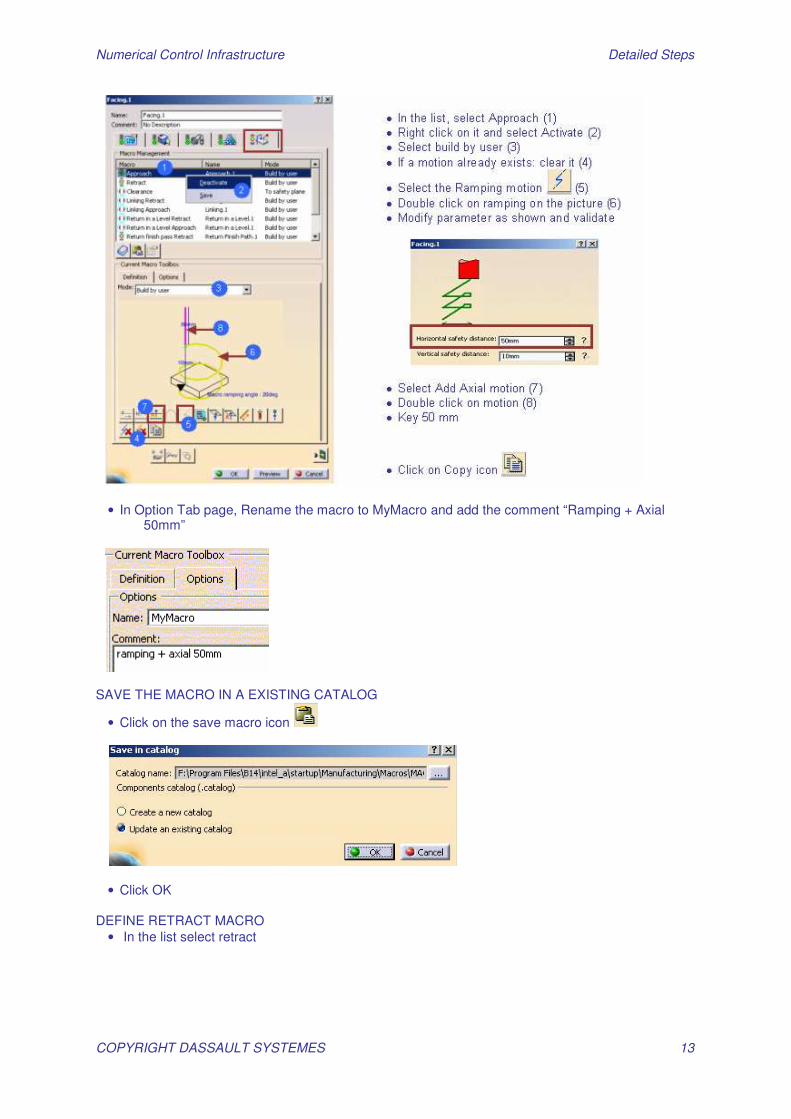
• Create an Approach and retract Macro
Numerical Control Infrastructure Detailed Steps
COPYRIGHT DASSAULT SYSTEMES 13
• In Option Tab page, Rename the macro to MyMacro and add the comment “Ramping + Axial 50mm”
SAVE THE MACRO IN A EXISTING CATALOG
• Click on the save macro icon
• Click OK DEFINE RETRACT MACRO
• In the list select retract
Numerical Control Infrastructure Detailed Steps
COPYRIGHT DASSAULT SYSTEMES 14
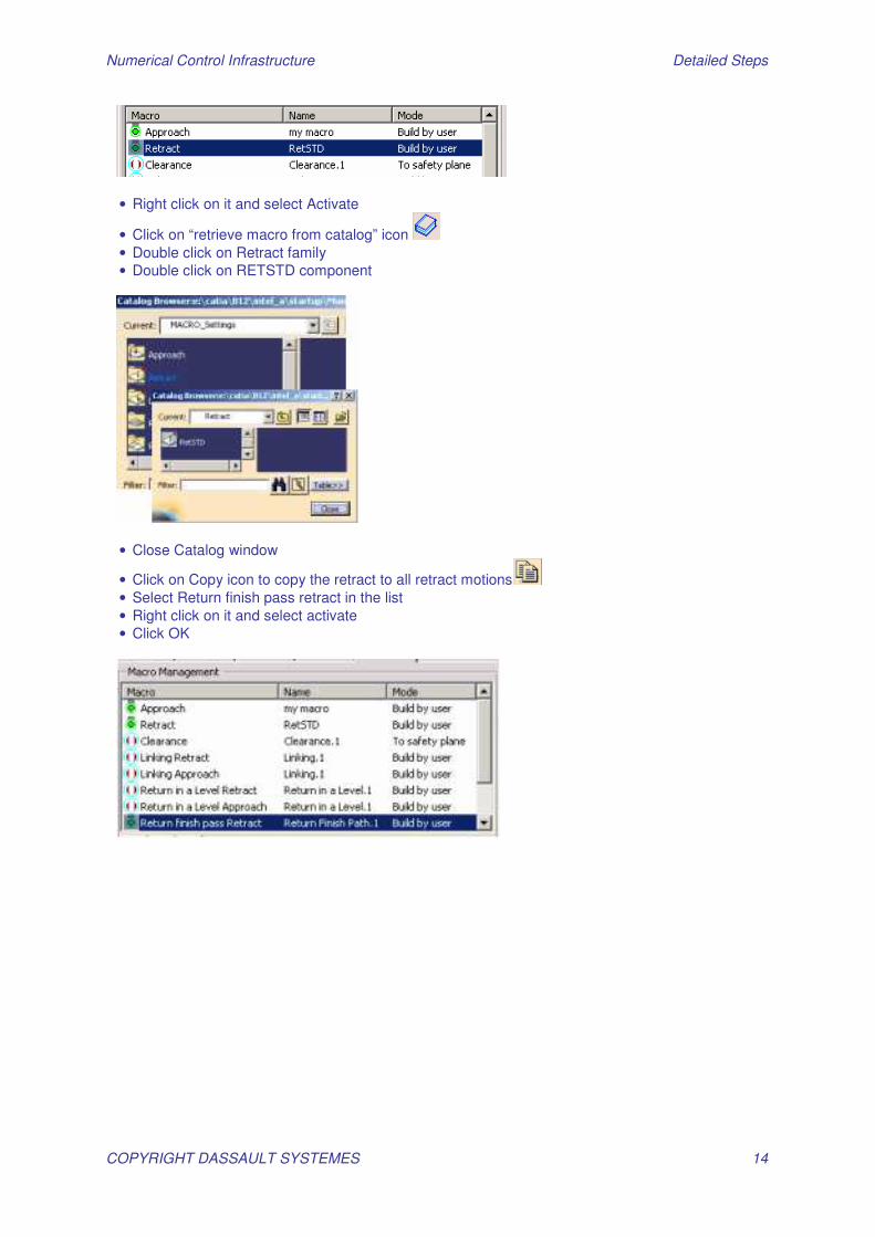
• Right click on it and select Activate
• Click on “retrieve macro from catalog” icon • Double click on Retract family • Double click on RETSTD component
• Close Catalog window
• Click on Copy icon to copy the retract to all retract motions • Select Return finish pass retract in the list • Right click on it and select activate • Click OK

Numerical Control Infrastructure Detailed Steps
COPYRIGHT DASSAULT SYSTEMES 15
Step 2B: Replay and Material Removal Simulation Open Start_Step2B_ReplaySimulateAnalyze.CATProcess
1.13 - Replay Machining Operations
• Select Manufacturing Program1 in Setup1
• Compute tool path using contextual menu
• Replay the tool path
• Use replay buttons to visualize tool path
• Select Color mode icon to see the different motions (rapid, approach, retract, machining)
• Select your replay mode (in continuous or Point by Point etc)
• Select tool mode: select tool axis mode
Numerical Control Infrastructure Detailed Steps
COPYRIGHT DASSAULT SYSTEMES 16
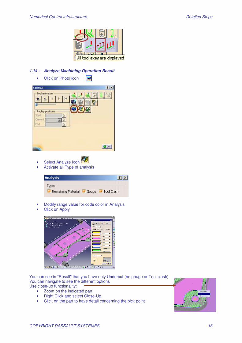
1.14 - Analyze Machining Operation Result
• Click on Photo icon
• Select Analyze Icon • Activate all Type of analysis
• Modify range value for code color in Analysis • Click on Apply
You can see in “Result” that you have only Undercut (no gouge or Tool clash) You can navigate to see the different options Use close-up functionality:
• Zoom on the indicated part • Right Click and select Close-Up • Click on the part to have detail concerning the pick point
Numerical Control Infrastructure Detailed Steps
COPYRIGHT DASSAULT SYSTEMES 17
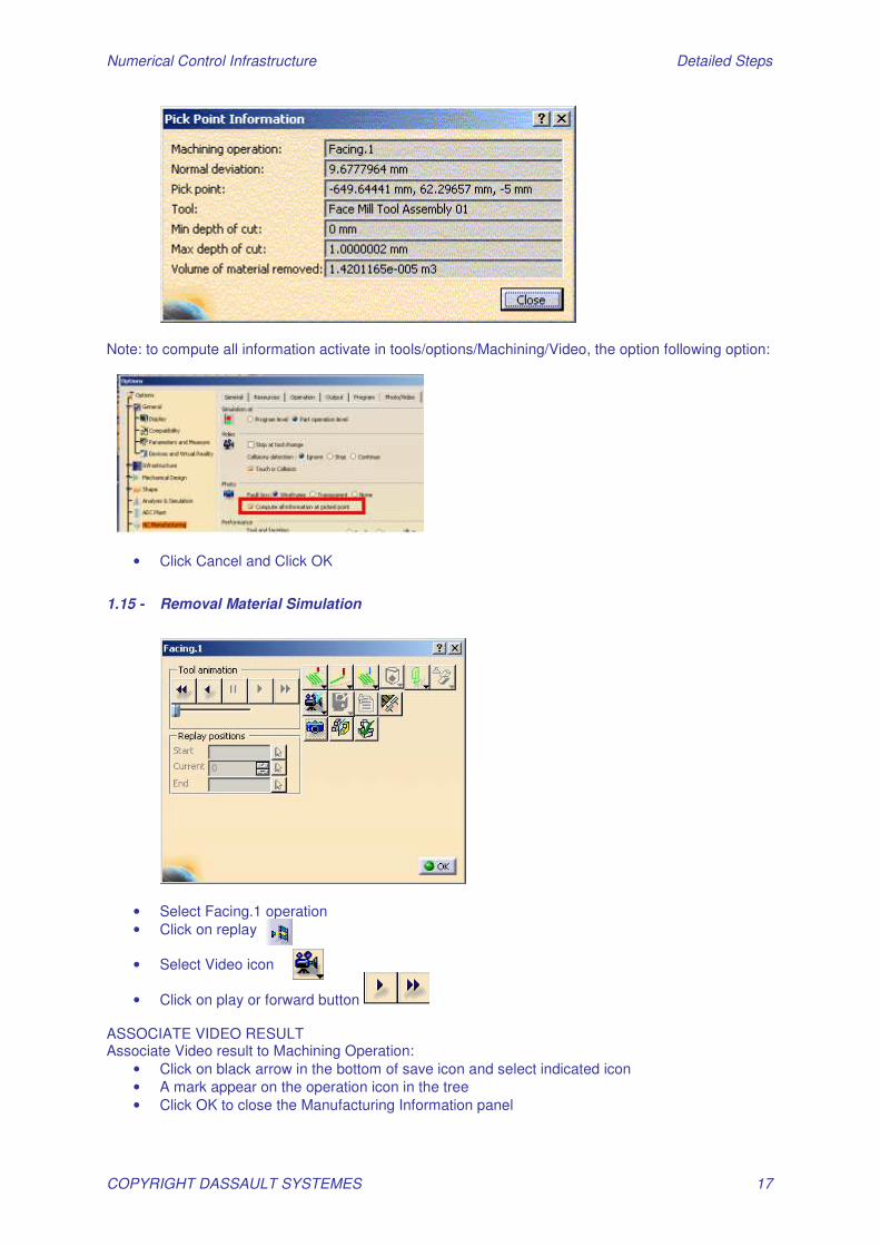
Note: to compute all information activate in tools/options/Machining/Video, the option following option:
• Click Cancel and Click OK
1.15 - Removal Material Simulation
• Select Facing.1 operation • Click on replay
• Select Video icon
• Click on play or forward button ASSOCIATE VIDEO RESULT Associate Video result to Machining Operation:
• Click on black arrow in the bottom of save icon and select indicated icon • A mark appear on the operation icon in the tree • Click OK to close the Manufacturing Information panel
Numerical Control Infrastructure Detailed Steps
COPYRIGHT DASSAULT SYSTEMES 18
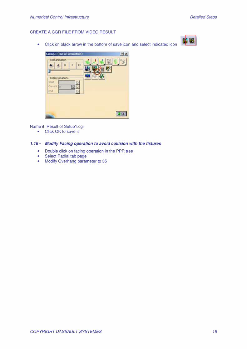
CREATE A CGR FILE FROM VIDEO RESULT
• Click on black arrow in the bottom of save icon and select indicated icon
Name it: Result of Setup1.cgr
• Click OK to save it
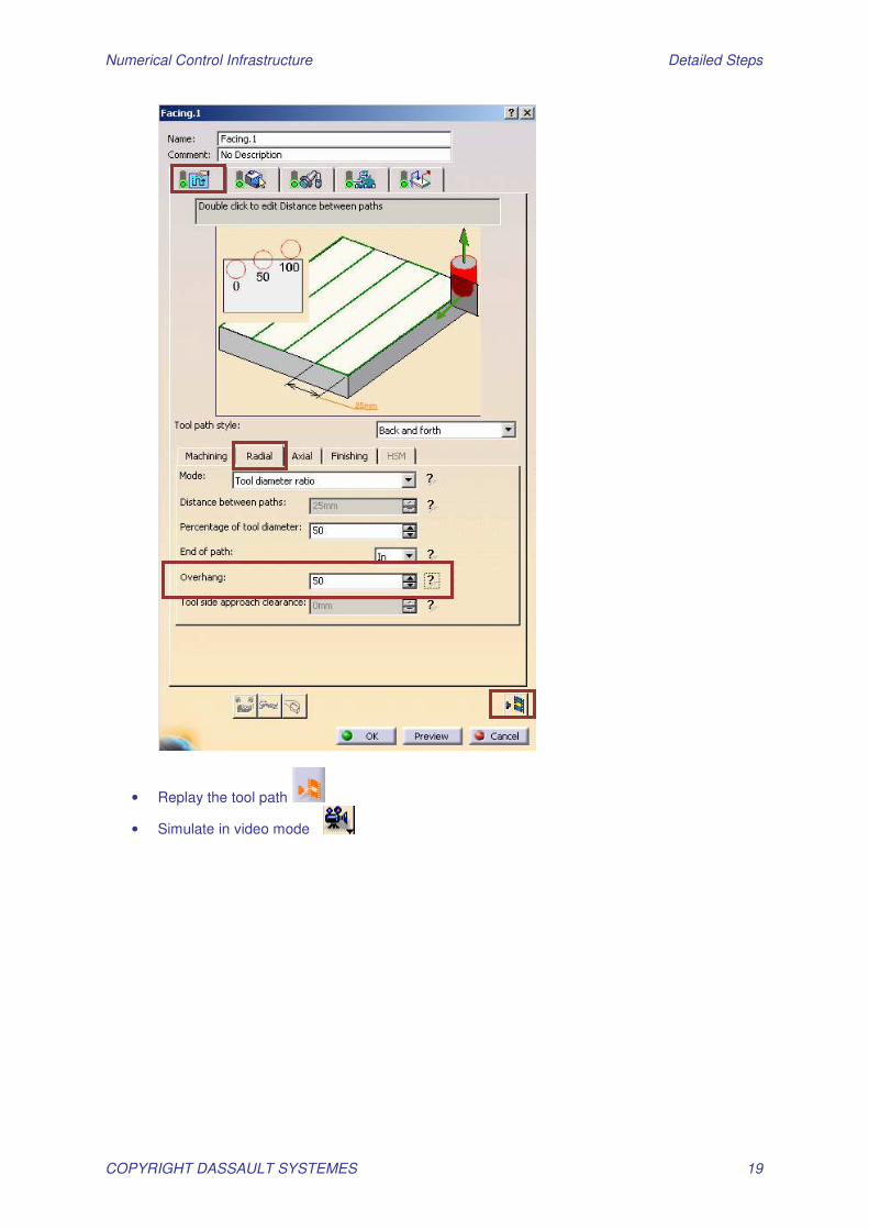
1.16 - Modify Facing operation to avoid collision with the fixtures
• Double click on facing operation in the PPR tree • Select Radial tab page • Modify Overhang parameter to 35
Numerical Control Infrastructure Detailed Steps
COPYRIGHT DASSAULT SYSTEMES 19
• Replay the tool path
• Simulate in video mode
Numerical Control Infrastructure Detailed Steps
COPYRIGHT DASSAULT SYSTEMES 20
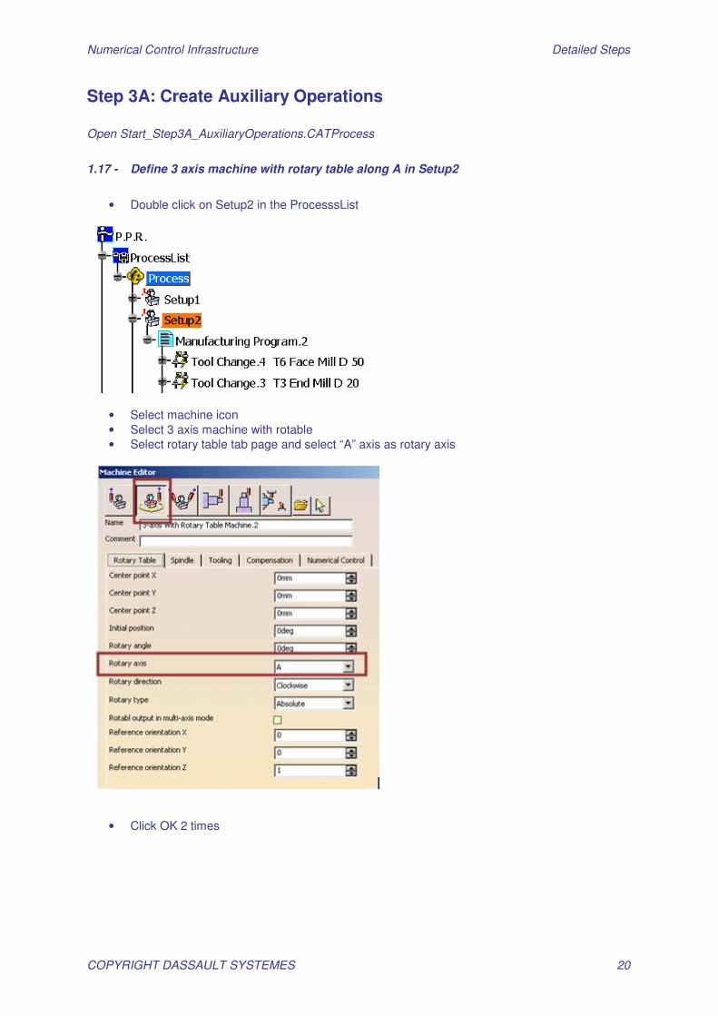
Step 3A: Create Auxiliary Operations Open Start_Step3A_AuxiliaryOperations.CATProcess
1.17 - Define 3 axis machine with rotary table along A in Setup2
• Double click on Setup2 in the ProcesssList
• Select machine icon • Select 3 axis machine with rotable • Select rotary table tab page and select “A” axis as rotary axis
• Click OK 2 times

Numerical Control Infrastructure Detailed Steps
COPYRIGHT DASSAULT SYSTEMES 21
1.18 - Generate a change of origin
• Select drilling tool change operation in the PPR tree
• Click on Machining Axis Change icon
• Select point as the center point on the panel (1) and click on the 3D on the following point (1) • Select Z-Direction on the panel (2) and select the inner hole in the 3D and click reverse
button: • Name this new Machining axis: LOCAL1
• Click OK to accept this new origin
1.19 - Auto Sequence Your Operations Define sequencing rules – it can be an administration task) In Menu / Tools / Options / Machining / Program: activate “Access to sequencing rules settings” Note: In some cases you may remove Read Only protection on the: ..\intel_a\startup\Manufacturing\Samples\AutoSequence\ AllSequencingRules.CATProduct File
Numerical Control Infrastructure Detailed Steps
COPYRIGHT DASSAULT SYSTEMES 22
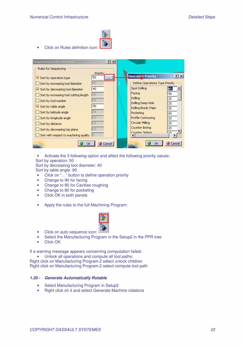
• Click on Rules definition icon:
• Activate the 3 following option and affect the following priority values: Sort by operation: 50 Sort by decreasing tool diameter: 40 Sort by table angle: 90
• Click on “…” button to define operation priority • Change to 90 for facing • Change to 85 for Cavities roughing • Change to 80 for pocketing • Click OK in both panels
• Apply the rules to the full Machining Program:
• Click on auto sequence icon: • Select the Manufacturing Program in the Setup2 in the PPR tree • Click OK
If a warning message appears concerning computation failed:
• Unlock all operations and compute all tool paths: Right click on Manufacturing Program.2 select unlock children Right click on Manufacturing Program.2 select compute tool path
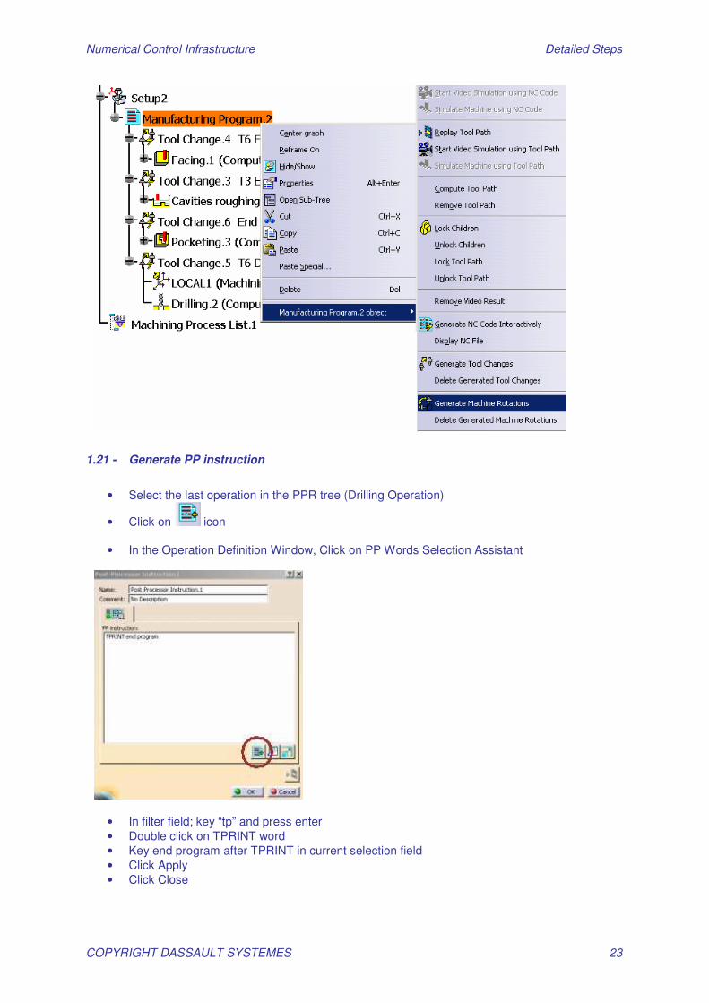
1.20 - Generate Automatically Rotable
• Select Manufacturing Program in Setup2 • Right click on it and select Generate Machine rotations
Numerical Control Infrastructure Detailed Steps
COPYRIGHT DASSAULT SYSTEMES 23
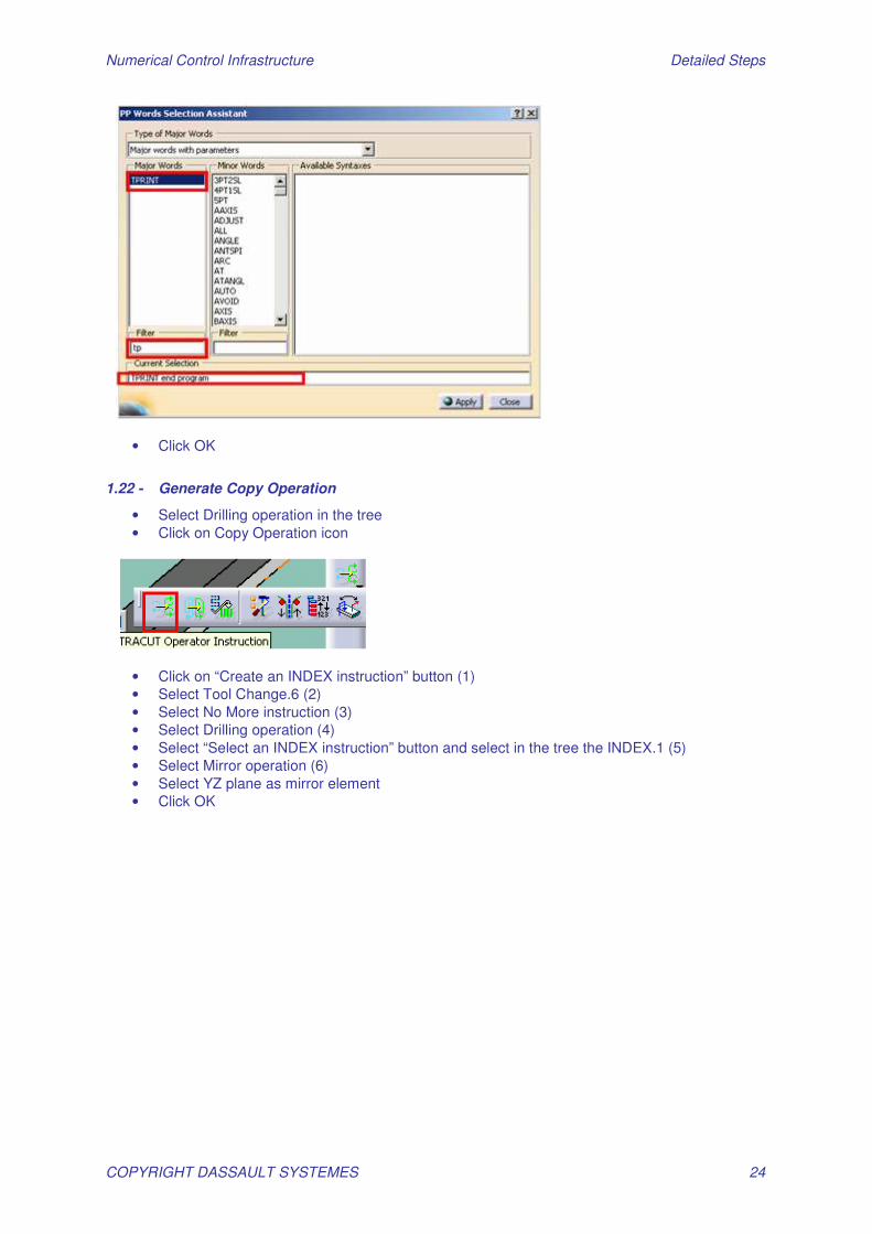
1.21 - Generate PP instruction
• Select the last operation in the PPR tree (Drilling Operation)
• Click on icon
• In the Operation Definition Window, Click on PP Words Selection Assistant
• In filter field; key “tp” and press enter • Double click on TPRINT word • Key end program after TPRINT in current selection field • Click Apply • Click Close
Numerical Control Infrastructure Detailed Steps
COPYRIGHT DASSAULT SYSTEMES 24
• Click OK
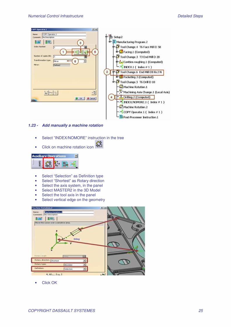
1.22 - Generate Copy Operation
• Select Drilling operation in the tree • Click on Copy Operation icon
• Click on “Create an INDEX instruction” button (1) • Select Tool Change.6 (2) • Select No More instruction (3) • Select Drilling operation (4) • Select “Select an INDEX instruction” button and select in the tree the INDEX.1 (5) • Select Mirror operation (6) • Select YZ plane as mirror element • Click OK
Numerical Control Infrastructure Detailed Steps
COPYRIGHT DASSAULT SYSTEMES 25
1.23 - Add manually a machine rotation
• Select ”INDEX/NOMORE” instruction in the tree
• Click on machine rotation icon
• Select “Selection” as Definition type • Select “Shortest” as Rotary direction • Select the axis system, in the panel • Select MASTER2 in the 3D Model • Select the tool axis in the panel • Select vertical edge on the geometry
• Click OK
Numerical Control Infrastructure Detailed Steps
COPYRIGHT DASSAULT SYSTEMES 26
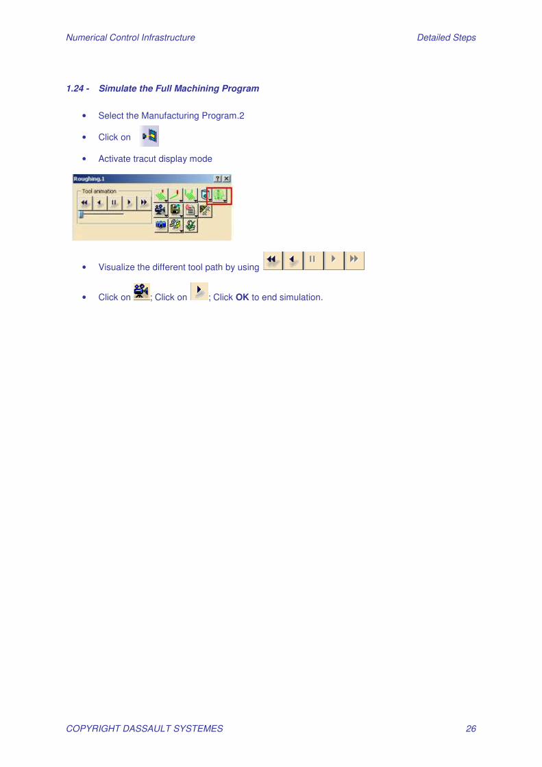
1.24 - Simulate the Full Machining Program
• Select the Manufacturing Program.2
• Click on
• Activate tracut display mode
• Visualize the different tool path by using
• Click on ; Click on ; Click OK to end simulation.
Numerical Control Infrastructure Detailed Steps
COPYRIGHT DASSAULT SYSTEMES 27
Step 3B: Create Spot drilling and Drilling Operations Open Start_Step3B_SpotDrillingAndDrilling.CATProcess
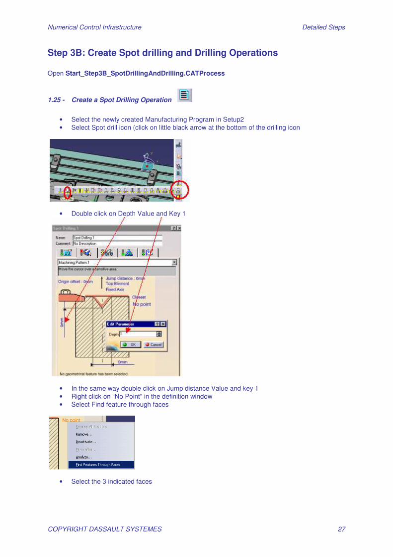
1.25 - Create a Spot Drilling Operation
• Select the newly created Manufacturing Program in Setup2 • Select Spot drill icon (click on little black arrow at the bottom of the drilling icon
• Double click on Depth Value and Key 1
• In the same way double click on Jump distance Value and key 1 • Right click on “No Point” in the definition window • Select Find feature through faces
• Select the 3 indicated faces
Numerical Control Infrastructure Detailed Steps
COPYRIGHT DASSAULT SYSTEMES 28
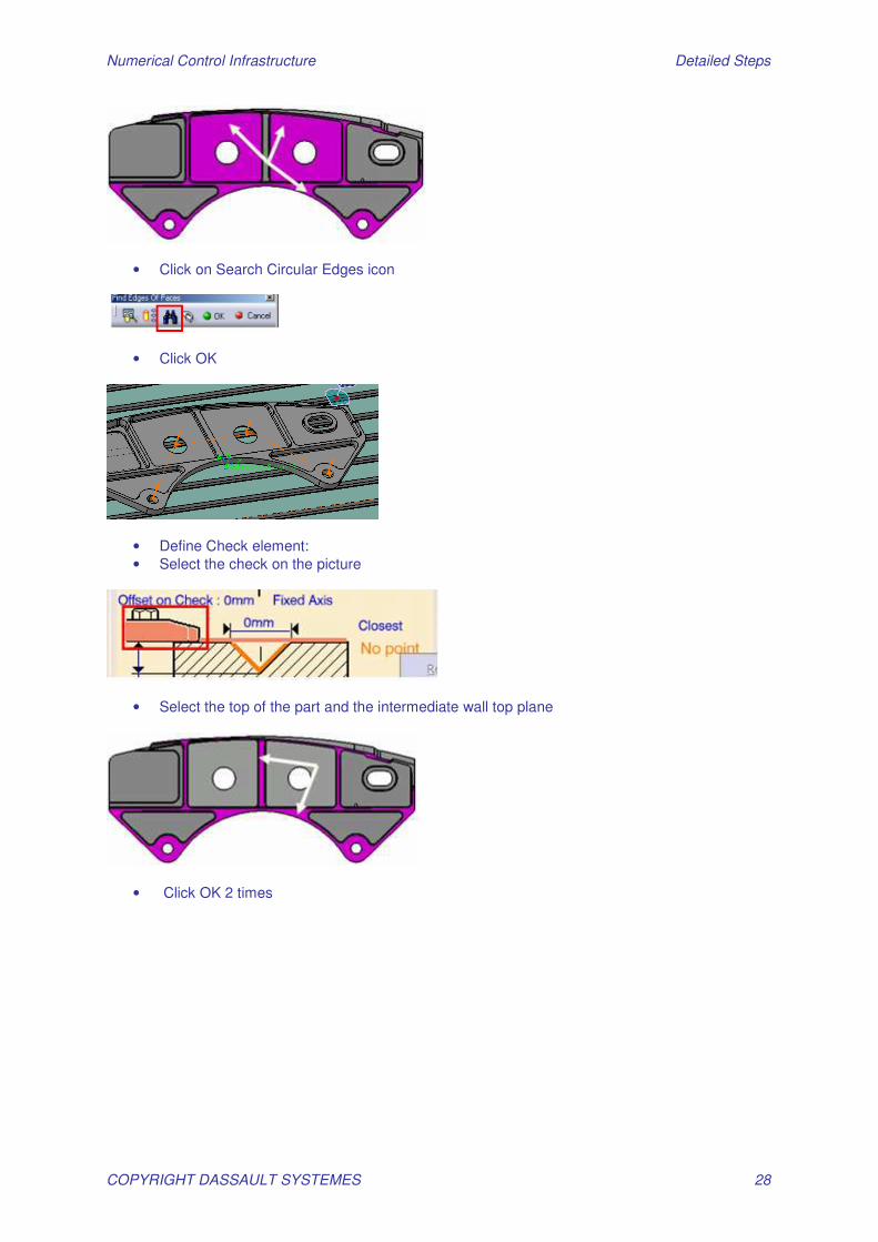
• Click on Search Circular Edges icon
• Click OK
• Define Check element: • Select the check on the picture
• Select the top of the part and the intermediate wall top plane
• Click OK 2 times
Numerical Control Infrastructure Detailed Steps
COPYRIGHT DASSAULT SYSTEMES 29
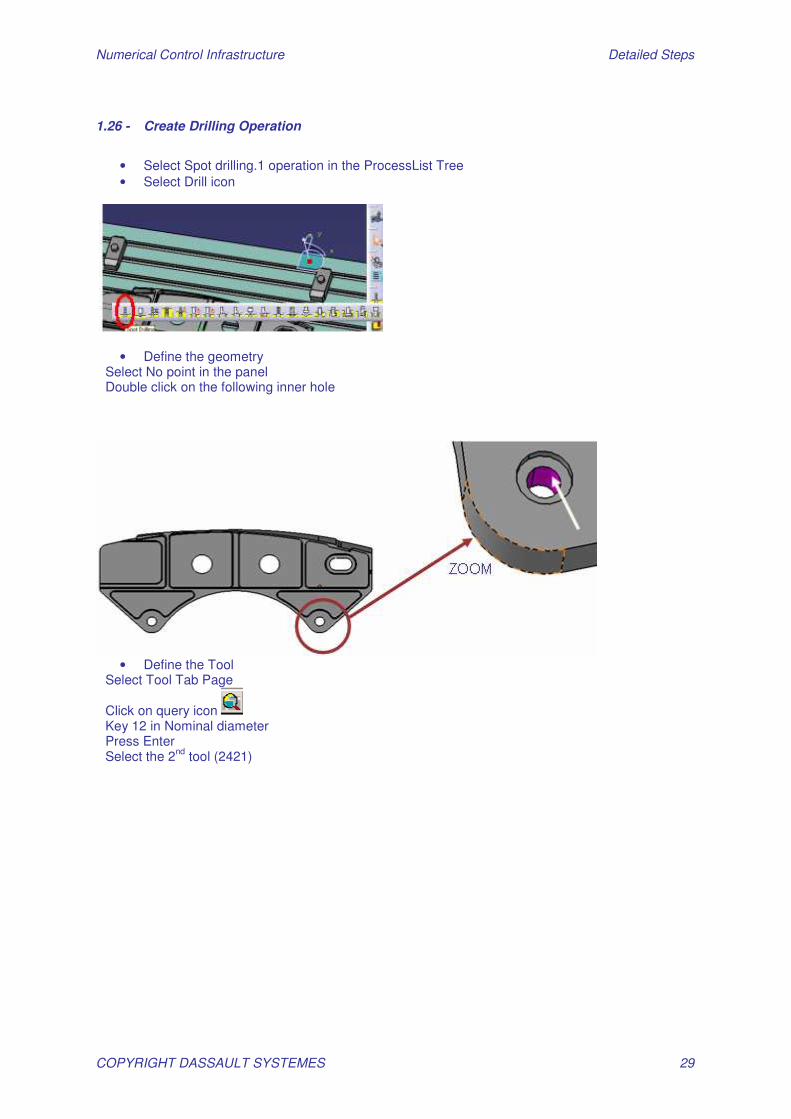
1.26 - Create Drilling Operation
• Select Spot drilling.1 operation in the ProcessList Tree • Select Drill icon
• Define the geometry Select No point in the panel Double click on the following inner hole
• Define the Tool
Select Tool Tab Page
Click on query icon Key 12 in Nominal diameter Press Enter Select the 2nd tool (2421)

Numerical Control Infrastructure Detailed Steps
COPYRIGHT DASSAULT SYSTEMES 30
Click OK
• Replay the operation Click on Replay icon Click OK two times to exit
1.27 - Create new Machining Pattern from existing one
• Open the Manufacturing View
• Select the Machining pattern of 4 holes • Select Machining pattern Object / New from current
• Right Click on Manufacturing View • Select Manufacturing view object / Sort by pattern
Numerical Control Infrastructure Detailed Steps
COPYRIGHT DASSAULT SYSTEMES 31
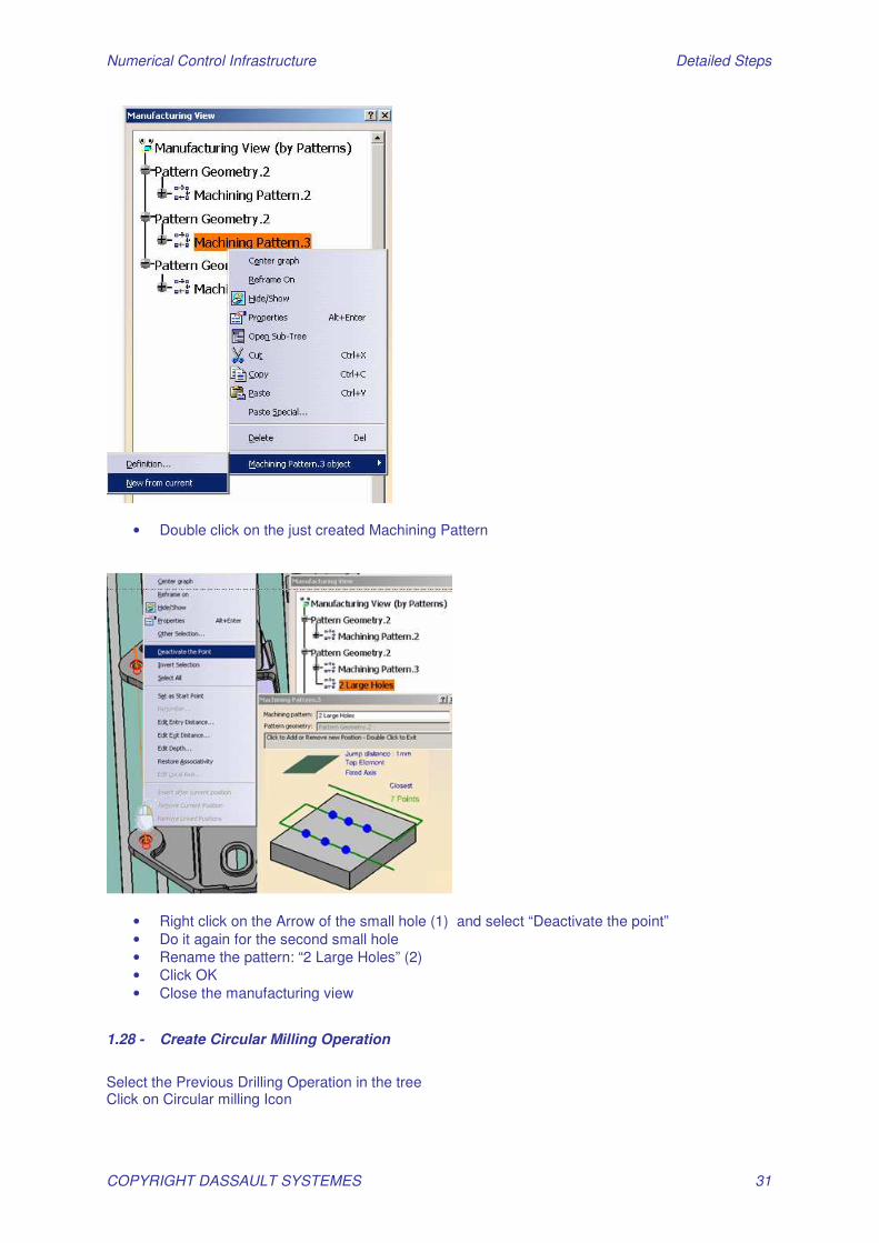
• Double click on the just created Machining Pattern
• Right click on the Arrow of the small hole (1) and select “Deactivate the point” • Do it again for the second small hole • Rename the pattern: “2 Large Holes” (2) • Click OK • Close the manufacturing view
1.28 - Create Circular Milling Operation
Select the Previous Drilling Operation in the tree Click on Circular milling Icon
Numerical Control Infrastructure Detailed Steps
COPYRIGHT DASSAULT SYSTEMES 32
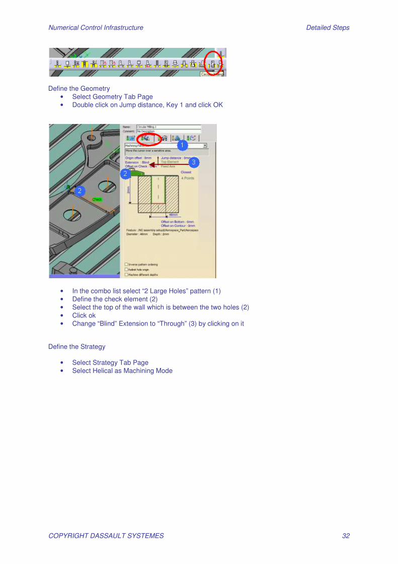
Define the Geometry
• Select Geometry Tab Page • Double click on Jump distance, Key 1 and click OK
• In the combo list select “2 Large Holes” pattern (1) • Define the check element (2) • Select the top of the wall which is between the two holes (2) • Click ok • Change “Blind” Extension to “Through” (3) by clicking on it
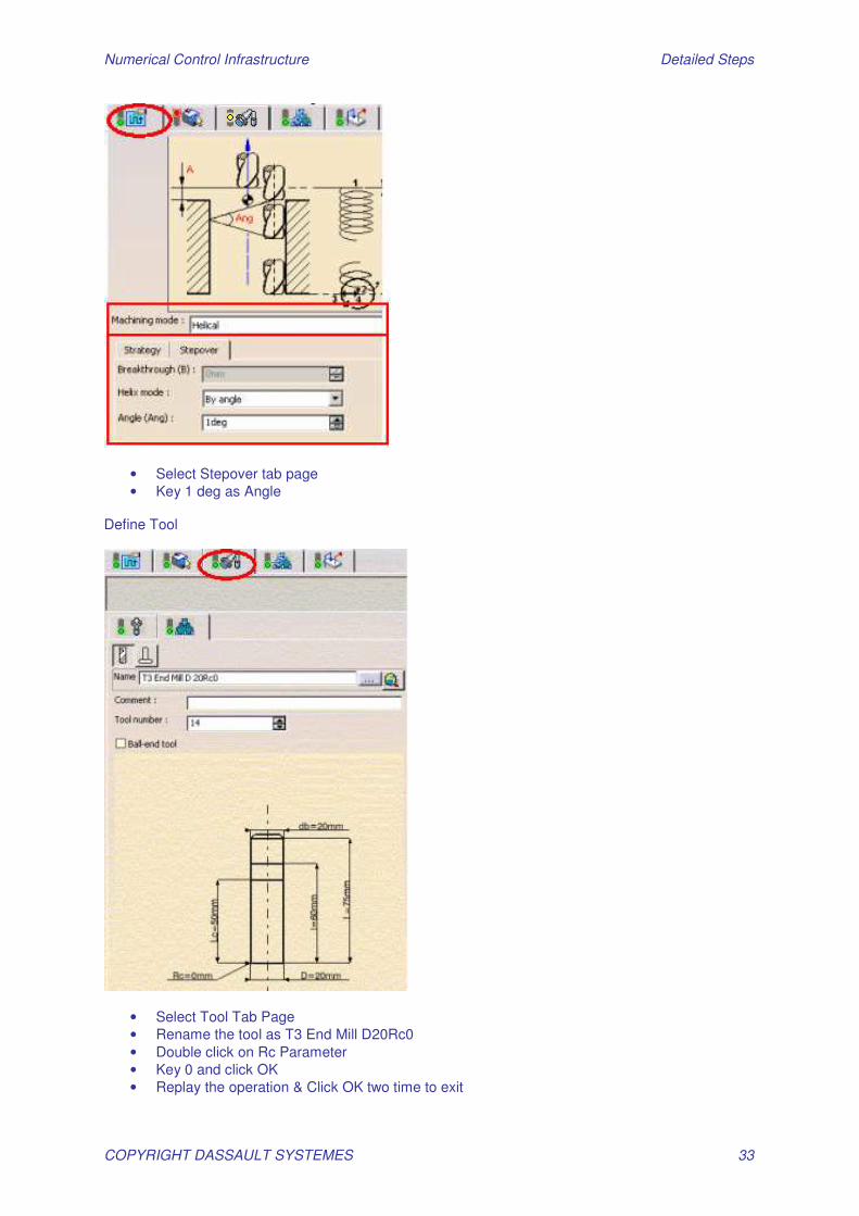
Define the Strategy
• Select Strategy Tab Page • Select Helical as Machining Mode
Numerical Control Infrastructure Detailed Steps
COPYRIGHT DASSAULT SYSTEMES 33
• Select Stepover tab page • Key 1 deg as Angle
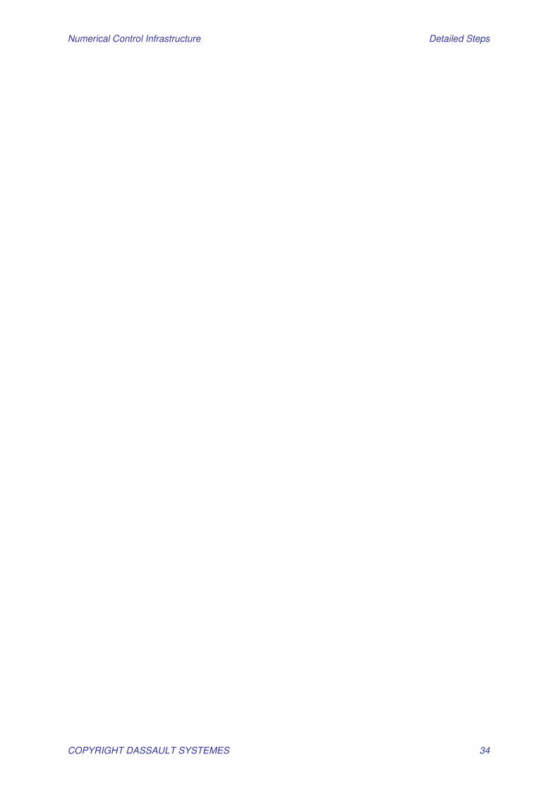
Define Tool
• Select Tool Tab Page • Rename the tool as T3 End Mill D20Rc0 • Double click on Rc Parameter • Key 0 and click OK • Replay the operation & Click OK two time to exit
Numerical Control Infrastructure Detailed Steps
COPYRIGHT DASSAULT SYSTEMES 34
Numerical Control Infrastructure Detailed Steps
COPYRIGHT DASSAULT SYSTEMES 35
Step 4: Generate Outputs Open Start_Step4_GenerateOutput.CATProcess
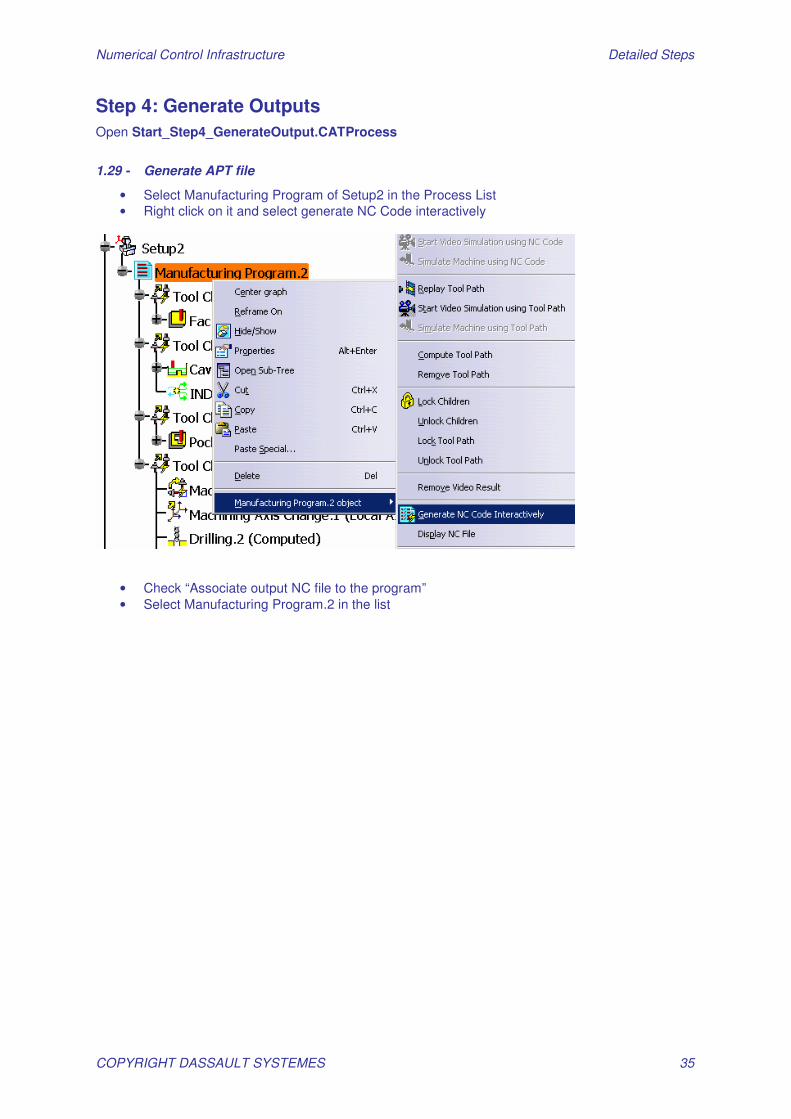
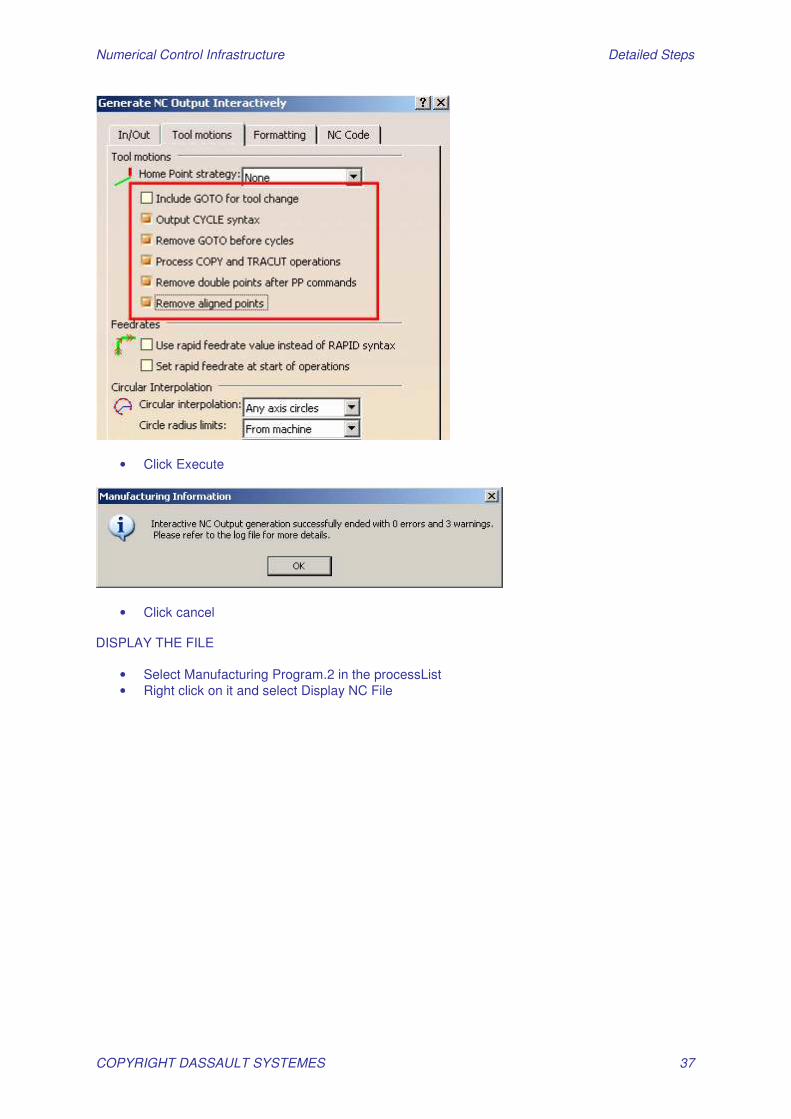
1.29 - Generate APT file
• Select Manufacturing Program of Setup2 in the Process List • Right click on it and select generate NC Code interactively
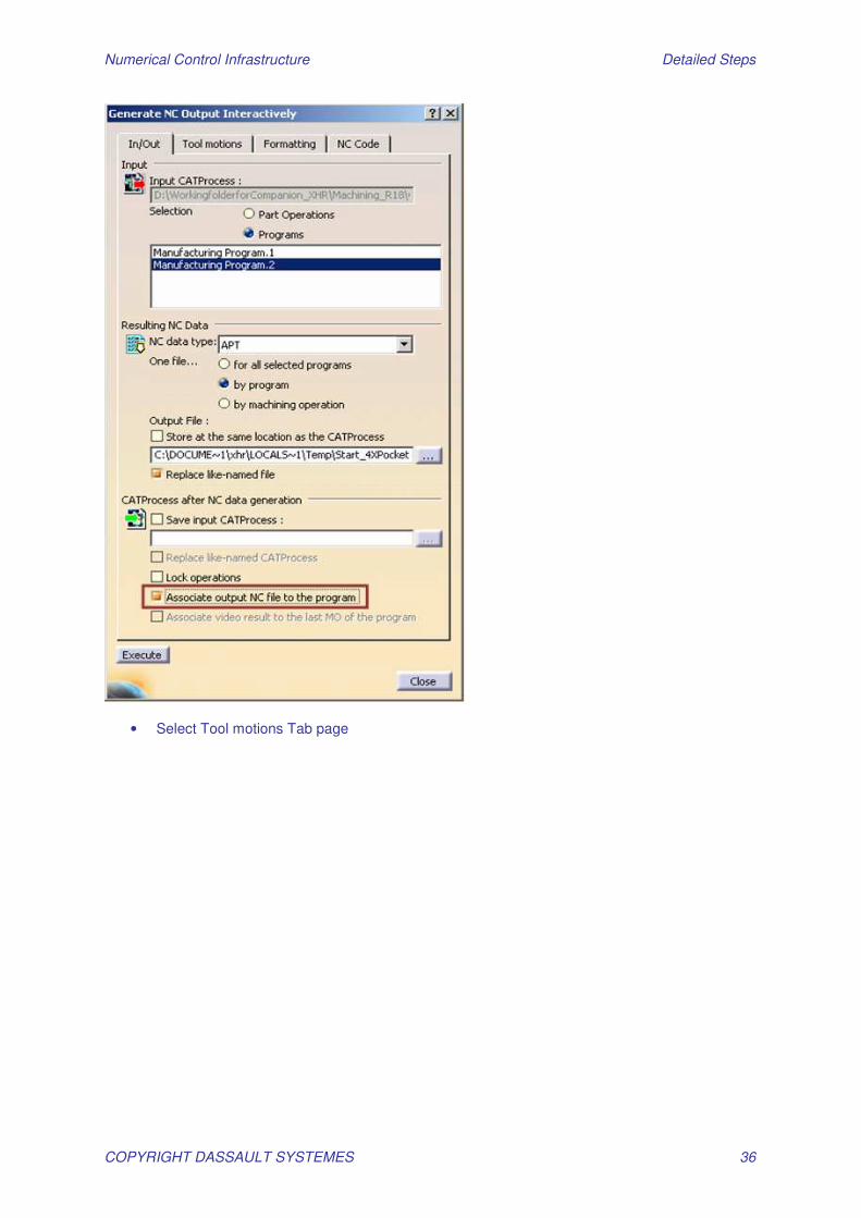
• Check “Associate output NC file to the program” • Select Manufacturing Program.2 in the list
Numerical Control Infrastructure Detailed Steps
COPYRIGHT DASSAULT SYSTEMES 36
• Select Tool motions Tab page
Numerical Control Infrastructure Detailed Steps
COPYRIGHT DASSAULT SYSTEMES 37
• Click Execute
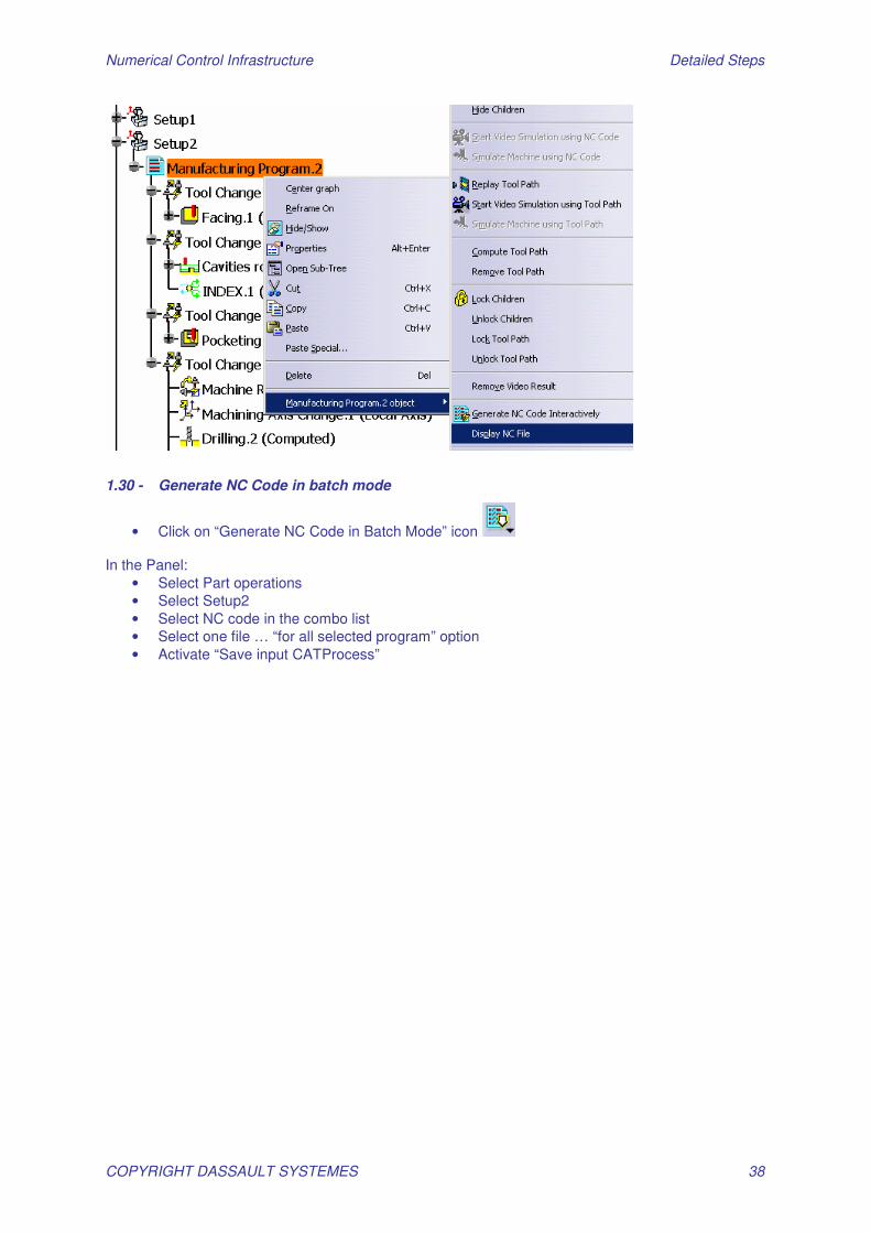
• Click cancel DISPLAY THE FILE
• Select Manufacturing Program.2 in the processList • Right click on it and select Display NC File
Numerical Control Infrastructure Detailed Steps
COPYRIGHT DASSAULT SYSTEMES 38
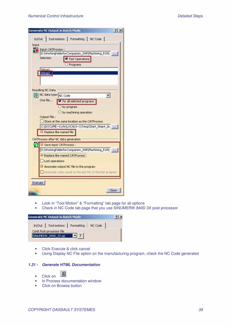
1.30 - Generate NC Code in batch mode
• Click on “Generate NC Code in Batch Mode” icon In the Panel:
• Select Part operations • Select Setup2 • Select NC code in the combo list • Select one file … “for all selected program” option • Activate “Save input CATProcess”
Numerical Control Infrastructure Detailed Steps
COPYRIGHT DASSAULT SYSTEMES 39
• Look in “Tool Motion” & “Formatting” tab page for all options • Check in NC Code tab page that you use SINUMERIK 840D 3X post processor
• Click Execute & click cancel • Using Display NC File option on the manufacturing program, check the NC Code generated
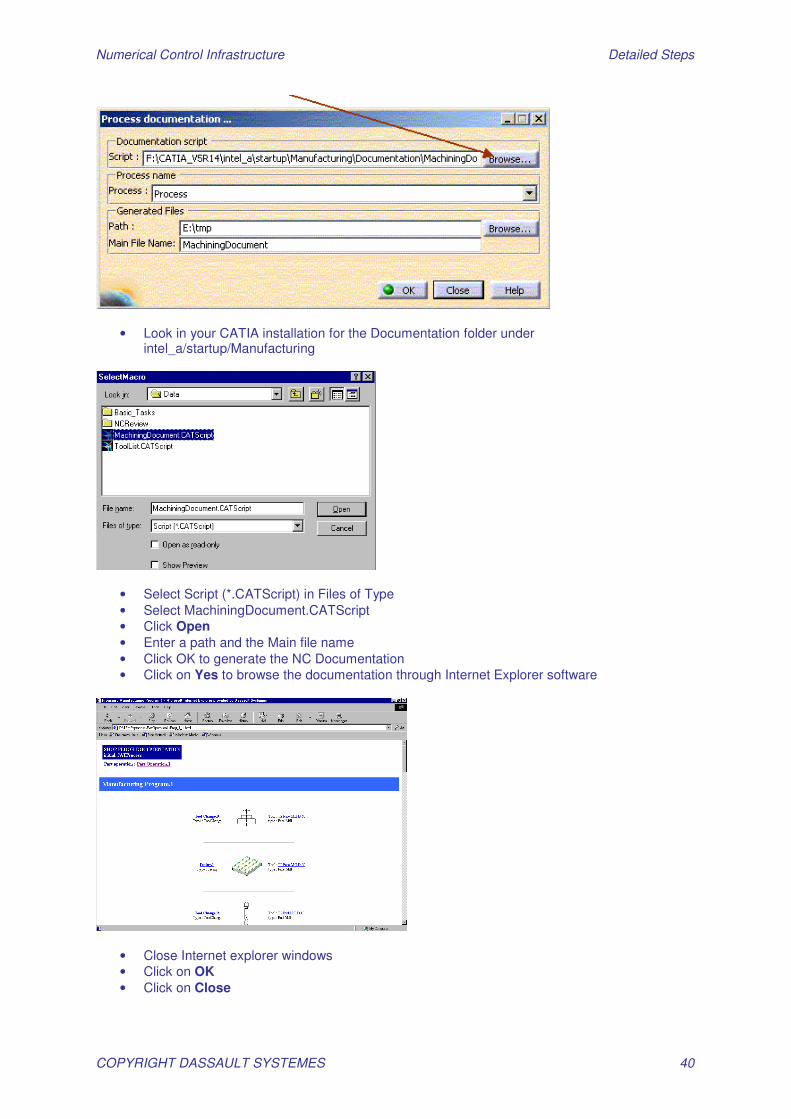
1.31 - Generate HTML Documentation
• Click on • In Process documentation window: • Click on Browse button
Numerical Control Infrastructure Detailed Steps
COPYRIGHT DASSAULT SYSTEMES 40
• Look in your CATIA installation for the Documentation folder under intel_a/startup/Manufacturing
• Select Script (*.CATScript) in Files of Type • Select MachiningDocument.CATScript • Click Open • Enter a path and the Main file name • Click OK to generate the NC Documentation • Click on Yes to browse the documentation through Internet Explorer software
• Close Internet explorer windows • Click on OK • Click on Close
Numerical Control Infrastructure Detailed Steps
COPYRIGHT DASSAULT SYSTEMES 41
Advanced Exercises
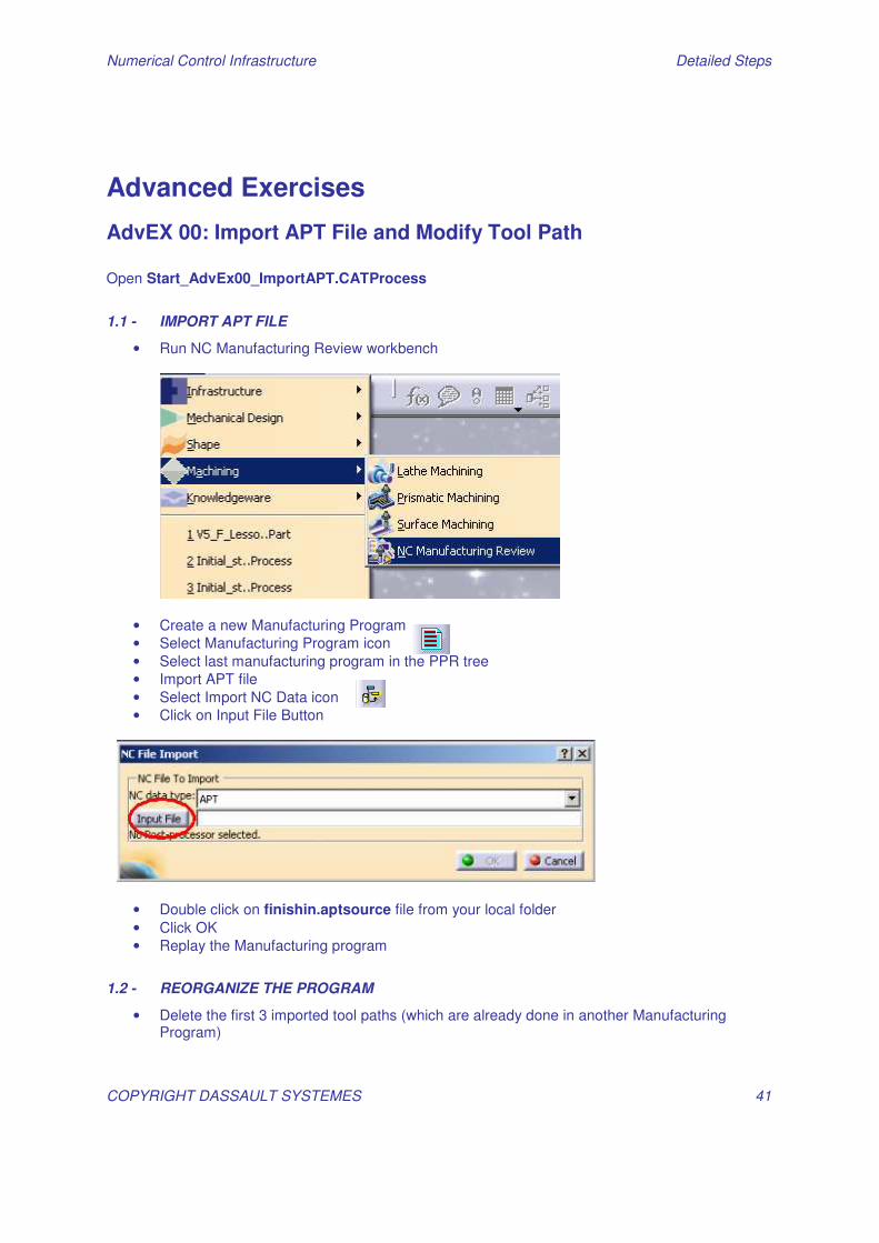
AdvEX 00: Import APT File and Modify Tool Path Open Start_AdvEx00_ImportAPT.CATProcess
1.1 - IMPORT APT FILE
• Run NC Manufacturing Review workbench
• Create a new Manufacturing Program • Select Manufacturing Program icon • Select last manufacturing program in the PPR tree • Import APT file • Select Import NC Data icon • Click on Input File Button
• Double click on finishin.aptsource file from your local folder • Click OK • Replay the Manufacturing program
1.2 - REORGANIZE THE PROGRAM
• Delete the first 3 imported tool paths (which are already done in another Manufacturing Program)
Numerical Control Infrastructure Detailed Steps
COPYRIGHT DASSAULT SYSTEMES 42
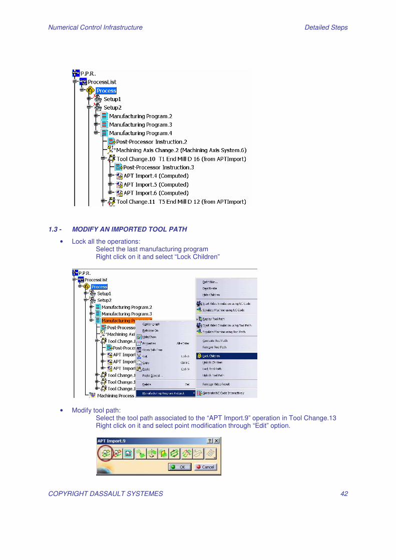
1.3 - MODIFY AN IMPORTED TOOL PATH
• Lock all the operations: Select the last manufacturing program Right click on it and select “Lock Children”
• Modify tool path: Select the tool path associated to the “APT Import.9” operation in Tool Change.13 Right click on it and select point modification through “Edit” option.
Numerical Control Infrastructure Detailed Steps
COPYRIGHT DASSAULT SYSTEMES 43
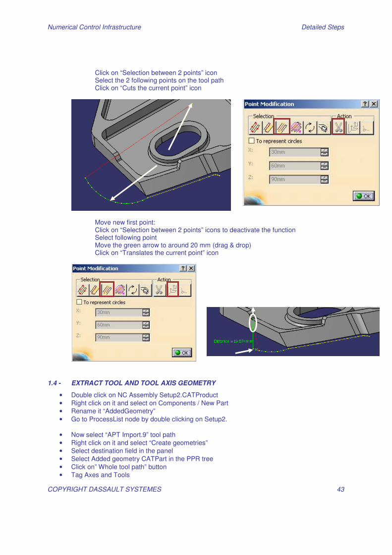
Click on “Selection between 2 points” icon Select the 2 following points on the tool path Click on “Cuts the current point” icon
Move new first point: Click on “Selection between 2 points” icons to deactivate the function Select following point Move the green arrow to around 20 mm (drag & drop) Click on “Translates the current point” icon
1.4 - EXTRACT TOOL AND TOOL AXIS GEOMETRY
• Double click on NC Assembly Setup2.CATProduct • Right click on it and select on Components / New Part • Rename it “AddedGeometry” • Go to ProcessList node by double clicking on Setup2.
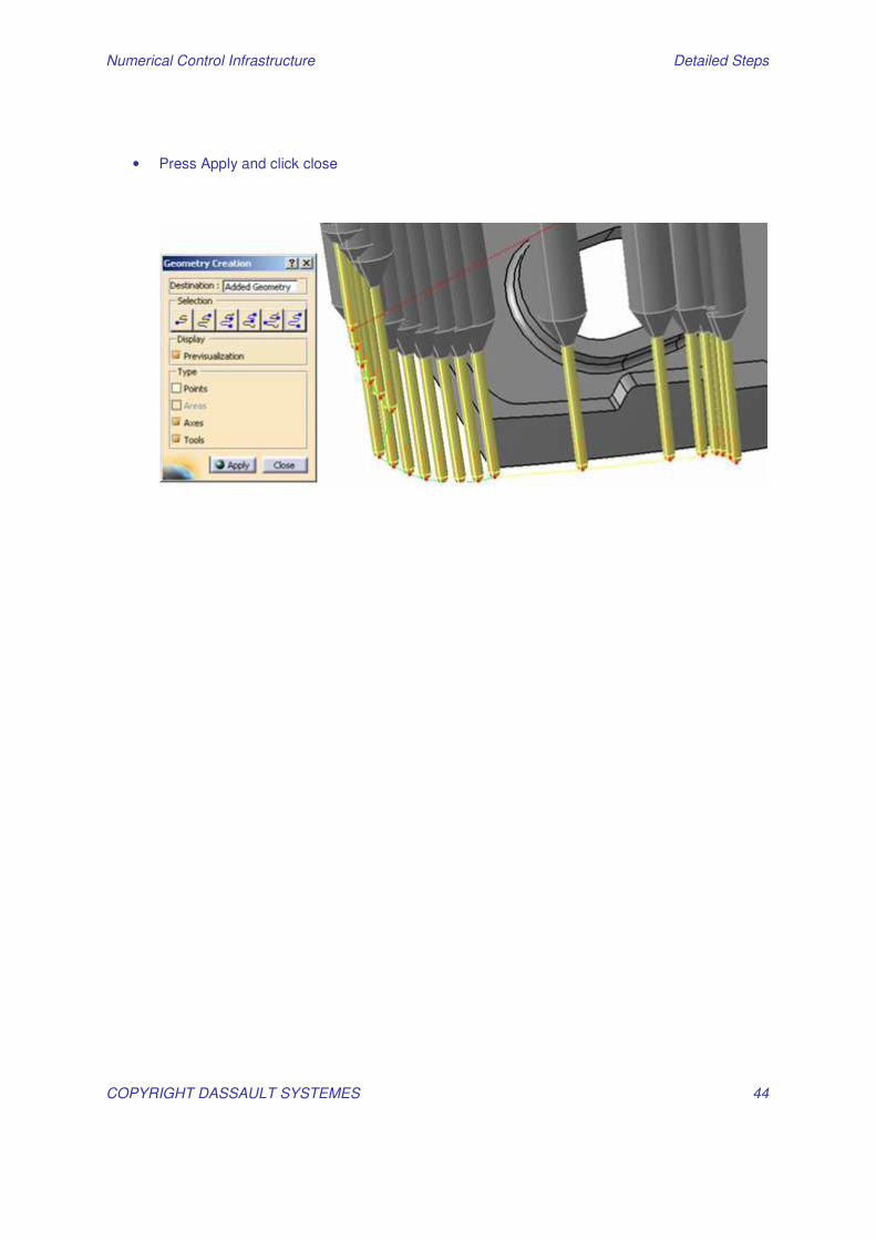
• Now select “APT Import.9” tool path • Right click on it and select “Create geometries” • Select destination field in the panel • Select Added geometry CATPart in the PPR tree • Click on” Whole tool path” button • Tag Axes and Tools
Numerical Control Infrastructure Detailed Steps
COPYRIGHT DASSAULT SYSTEMES 44
• Press Apply and click close
Numerical Control Infrastructure Detailed Steps
COPYRIGHT DASSAULT SYSTEMES 45
AdvEX 01: Import V4 Model
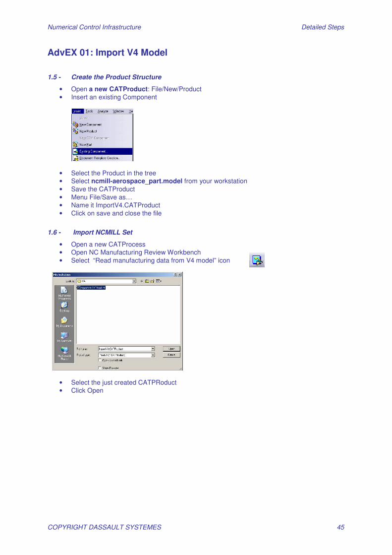
1.5 - Create the Product Structure
• Open a new CATProduct: File/New/Product • Insert an existing Component
• Select the Product in the tree • Select ncmill-aerospace_part.model from your workstation • Save the CATProduct • Menu File/Save as… • Name it ImportV4.CATProduct • Click on save and close the file
1.6 - Import NCMILL Set
• Open a new CATProcess • Open NC Manufacturing Review Workbench • Select “Read manufacturing data from V4 model” icon
• Select the just created CATPRoduct • Click Open
Numerical Control Infrastructure Detailed Steps
COPYRIGHT DASSAULT SYSTEMES 46
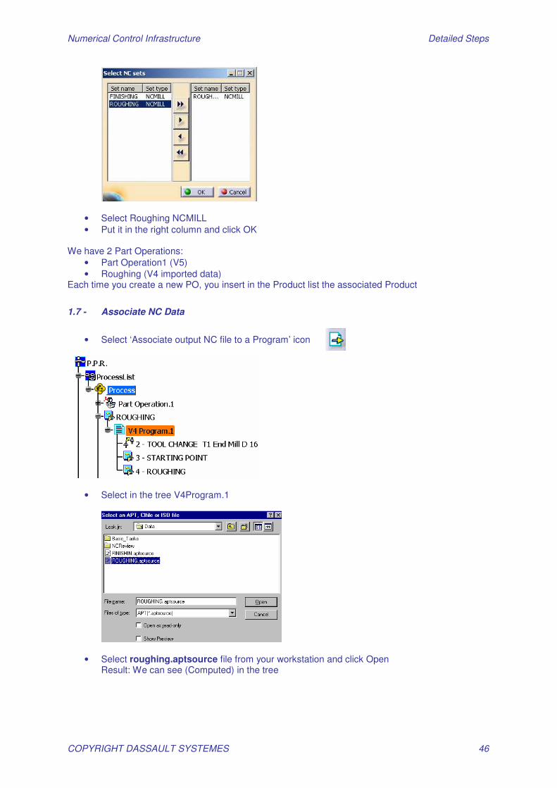
• Select Roughing NCMILL • Put it in the right column and click OK
We have 2 Part Operations:
• Part Operation1 (V5) • Roughing (V4 imported data)
Each time you create a new PO, you insert in the Product list the associated Product
1.7 - Associate NC Data
• Select ‘Associate output NC file to a Program’ icon
• Select in the tree V4Program.1
• Select roughing.aptsource file from your workstation and click Open Result: We can see (Computed) in the tree
Numerical Control Infrastructure Detailed Steps
COPYRIGHT DASSAULT SYSTEMES 47
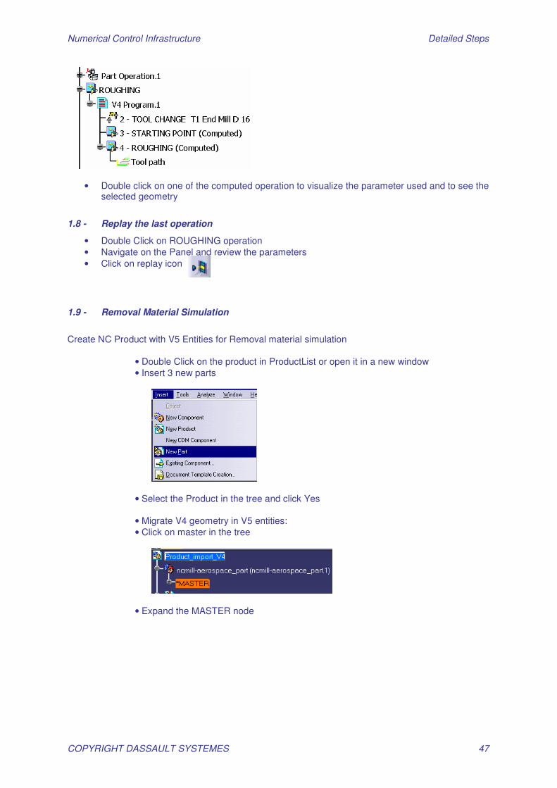
• Double click on one of the computed operation to visualize the parameter used and to see the selected geometry
1.8 - Replay the last operation
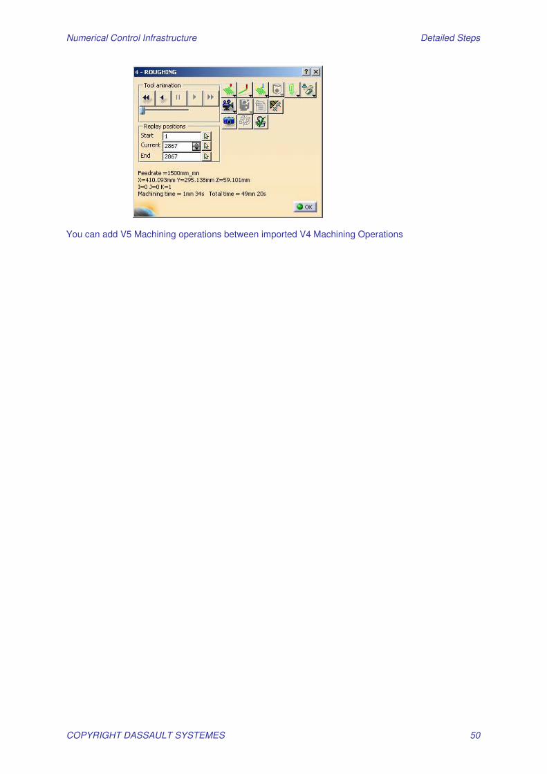
• Double Click on ROUGHING operation • Navigate on the Panel and review the parameters • Click on replay icon
1.9 - Removal Material Simulation
Create NC Product with V5 Entities for Removal material simulation
• Double Click on the product in ProductList or open it in a new window • Insert 3 new parts
• Select the Product in the tree and click Yes • Migrate V4 geometry in V5 entities: • Click on master in the tree
• Expand the MASTER node
Numerical Control Infrastructure Detailed Steps
COPYRIGHT DASSAULT SYSTEMES 48
Numerical Control Infrastructure Detailed Steps
COPYRIGHT DASSAULT SYSTEMES 49
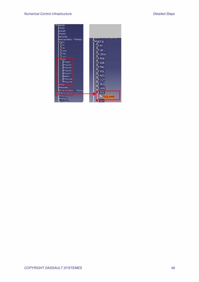
• Select SOL87 (Stock) • Ctrl C to copy it • Double click on the first new Part in the tree • MB3 and in contextual menu select Past Special / as CATIA_Result
• Select SOL474 to SOL477 & SOL1448 (Fixtures) • Ctrl C to copy it • Double click on the second new Part in the tree • MB3 and in contextual menu select Past Special / as CATIA_Result
• Select SOL1449 (Part) • Ctrl C to copy it • Double click on the third new Part in the tree • MB3 and in contextual menu select Past Special / as CATIA_Result
• Save the CATProduct and all the parts
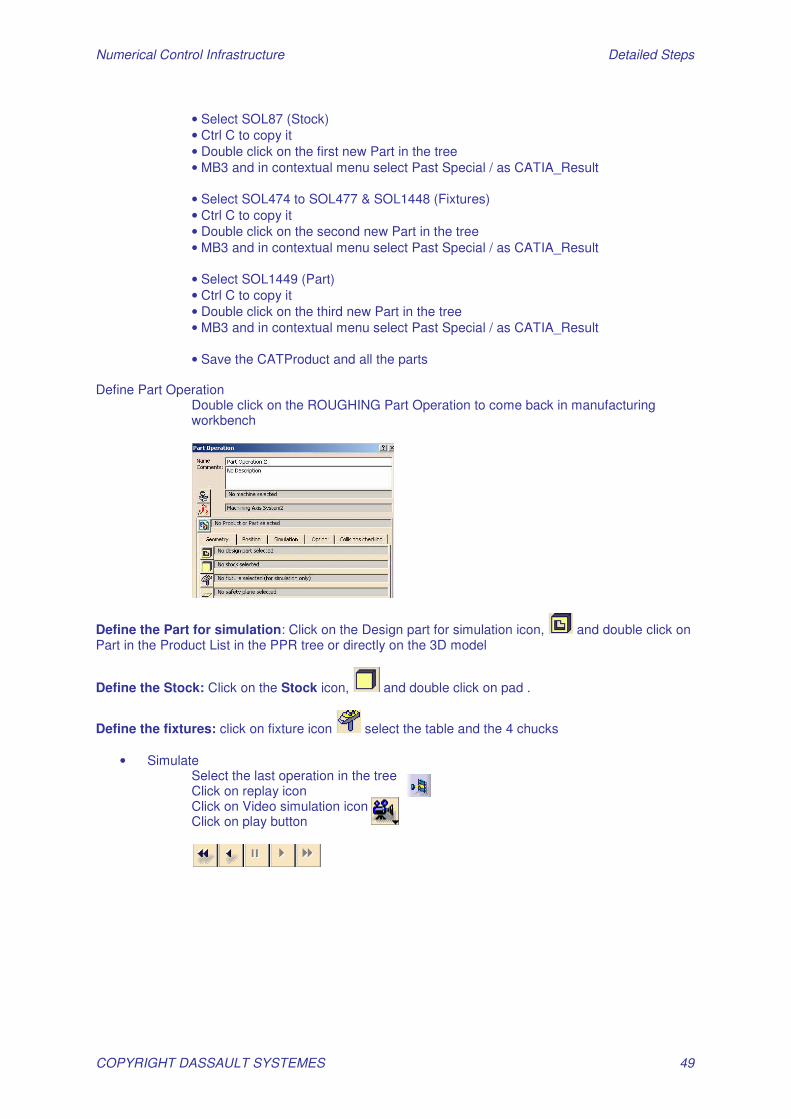
Define Part Operation
Double click on the ROUGHING Part Operation to come back in manufacturing workbench
Define the Part for simulation: Click on the Design part for simulation icon, and double click on Part in the Product List in the PPR tree or directly on the 3D model
Define the Stock: Click on the Stock icon, and double click on pad .
Define the fixtures: click on fixture icon select the table and the 4 chucks
• Simulate Select the last operation in the tree Click on replay icon Click on Video simulation icon Click on play button
Numerical Control Infrastructure Detailed Steps
COPYRIGHT DASSAULT SYSTEMES 50
You can add V5 Machining operations between imported V4 Machining Operations

Numerical Control Infrastructure Detailed Steps
COPYRIGHT DASSAULT SYSTEMES 51
AdvEX 02: Create a Machining Process and Instantiate It in the Current Model from Catalog
1.10 - Create a Predefined Machining Process
• Open a New CATProcess in Prismatic Machining workbench • Activate the Machining process tool bar (if not activated) • View/Toolbars/Machining Process
Open the Machining Process View
• Click on Machining Process View icon
• Create a new machining process
• Click on Machining Process icon Create your process sequence
• Select Spot drilling icon
• Click OK to close the operation definition windows
• Select Drilling icon
Numerical Control Infrastructure Detailed Steps
COPYRIGHT DASSAULT SYSTEMES 52
• Click OK to close the operation definition windows
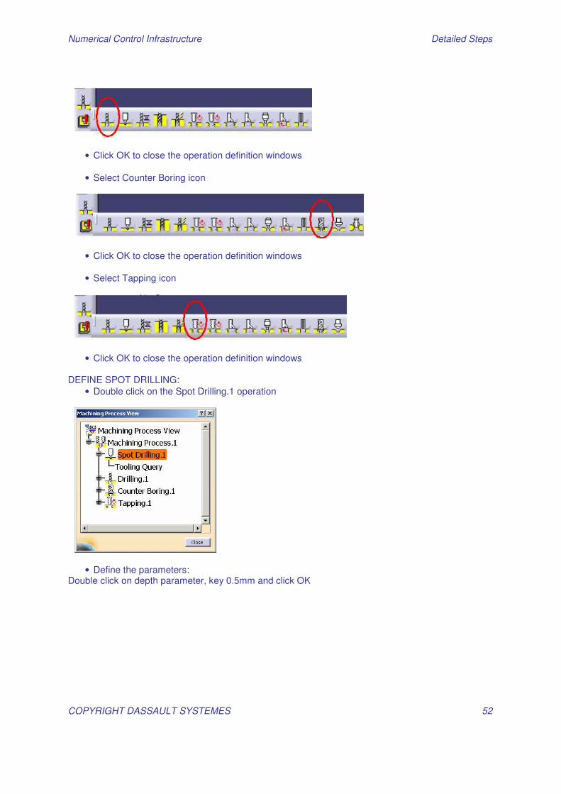
• Select Counter Boring icon
• Click OK to close the operation definition windows
• Select Tapping icon
• Click OK to close the operation definition windows DEFINE SPOT DRILLING:
• Double click on the Spot Drilling.1 operation
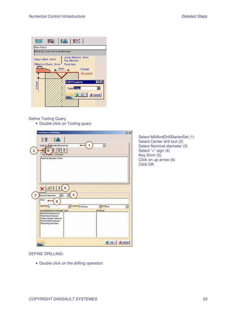
• Define the parameters: Double click on depth parameter, key 0.5mm and click OK
Numerical Control Infrastructure Detailed Steps
COPYRIGHT DASSAULT SYSTEMES 53
Define Tooling Query
• Double click on Tooling query
DEFINE DRILLING:
• Double click on the drilling operation
Select MillAndDrillStarterSet (1) Select Center drill tool (2) Select Nominal diameter (3) Select “<” sign (4) Key 5mm (5) Click on up arrow (6) Click OK
Numerical Control Infrastructure Detailed Steps
COPYRIGHT DASSAULT SYSTEMES 54
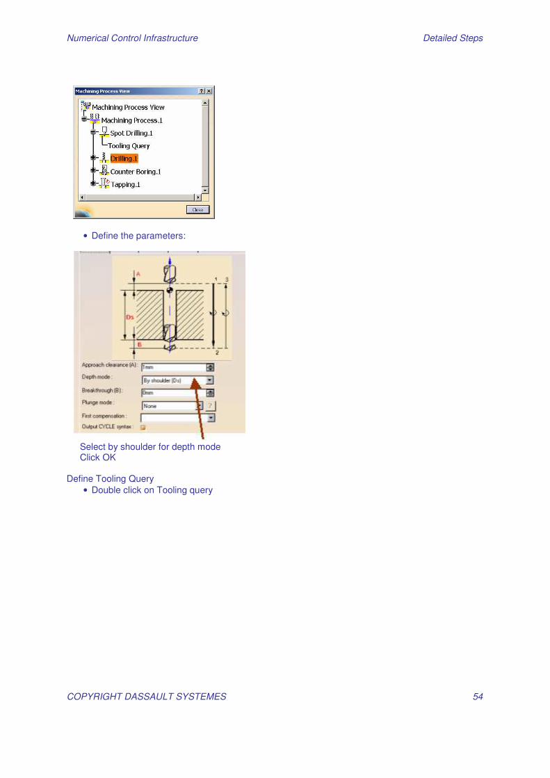
• Define the parameters:
Select by shoulder for depth mode Click OK Define Tooling Query
• Double click on Tooling query
Numerical Control Infrastructure Detailed Steps
COPYRIGHT DASSAULT SYSTEMES 55
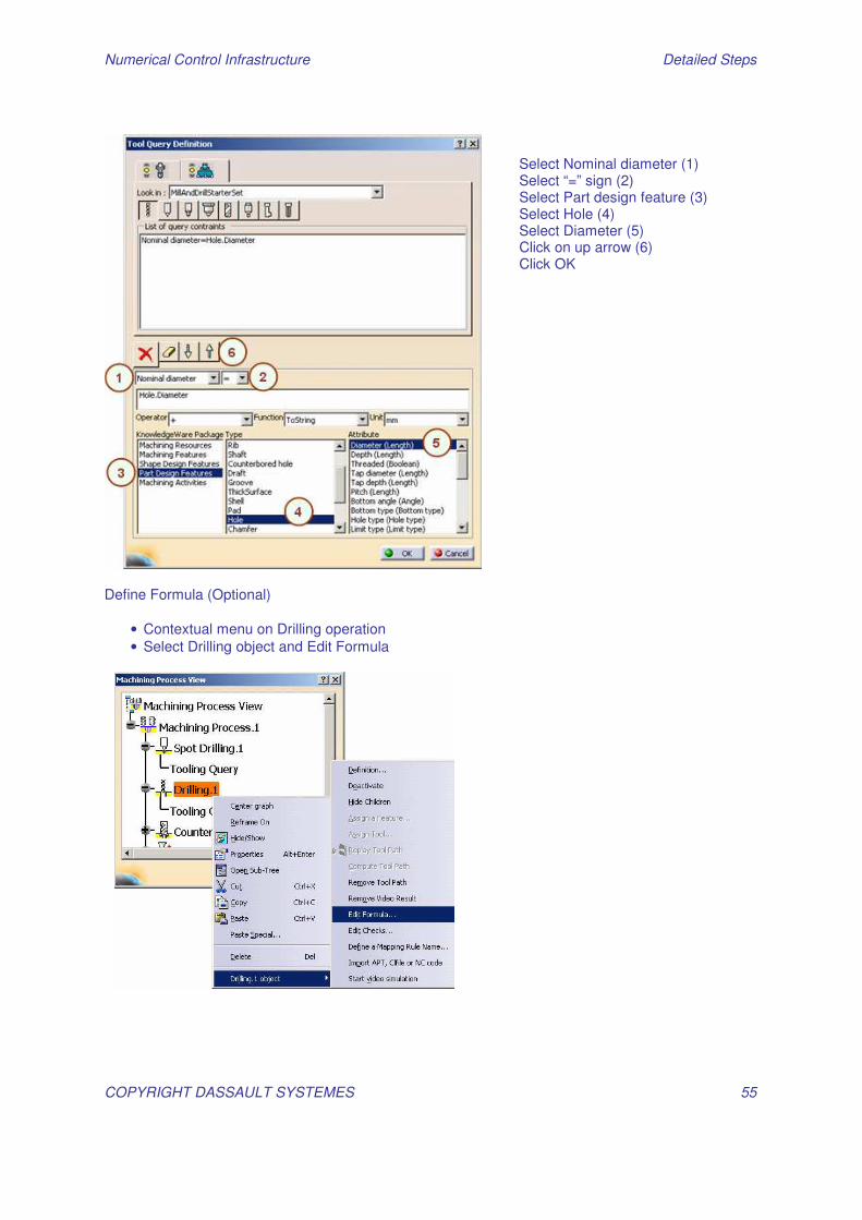
Define Formula (Optional)
• Contextual menu on Drilling operation • Select Drilling object and Edit Formula
Select Nominal diameter (1) Select “=” sign (2) Select Part design feature (3) Select Hole (4) Select Diameter (5) Click on up arrow (6) Click OK
Numerical Control Infrastructure Detailed Steps
COPYRIGHT DASSAULT SYSTEMES 56
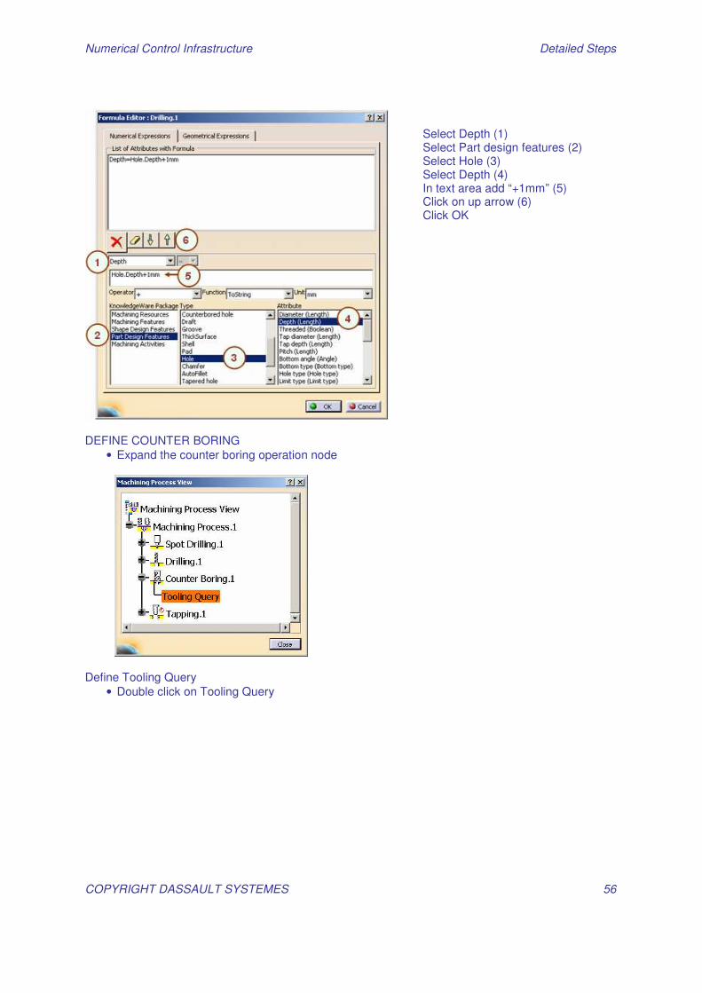
DEFINE COUNTER BORING
• Expand the counter boring operation node
Define Tooling Query
• Double click on Tooling Query
Select Depth (1) Select Part design features (2) Select Hole (3) Select Depth (4) In text area add “+1mm” (5) Click on up arrow (6) Click OK
Numerical Control Infrastructure Detailed Steps
COPYRIGHT DASSAULT SYSTEMES 57
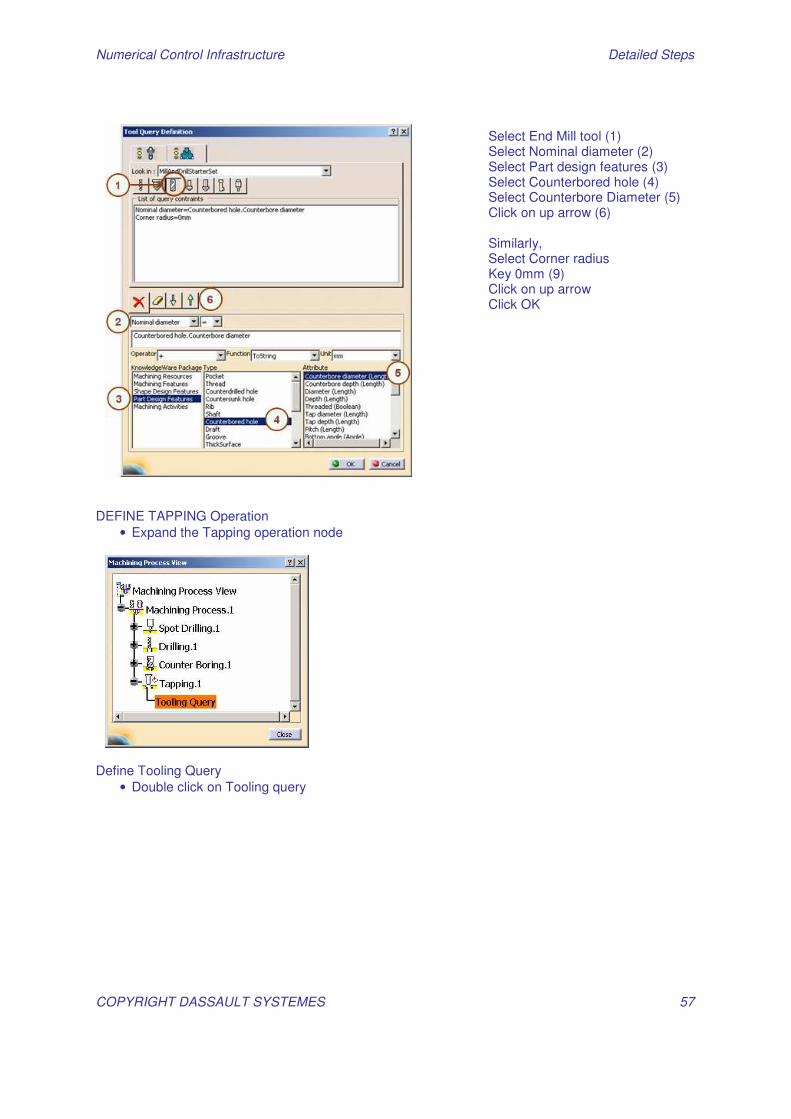
DEFINE TAPPING Operation
• Expand the Tapping operation node
Define Tooling Query
• Double click on Tooling query
Select End Mill tool (1) Select Nominal diameter (2) Select Part design features (3) Select Counterbored hole (4) Select Counterbore Diameter (5) Click on up arrow (6) Similarly, Select Corner radius Key 0mm (9) Click on up arrow Click OK
Numerical Control Infrastructure Detailed Steps
COPYRIGHT DASSAULT SYSTEMES 58
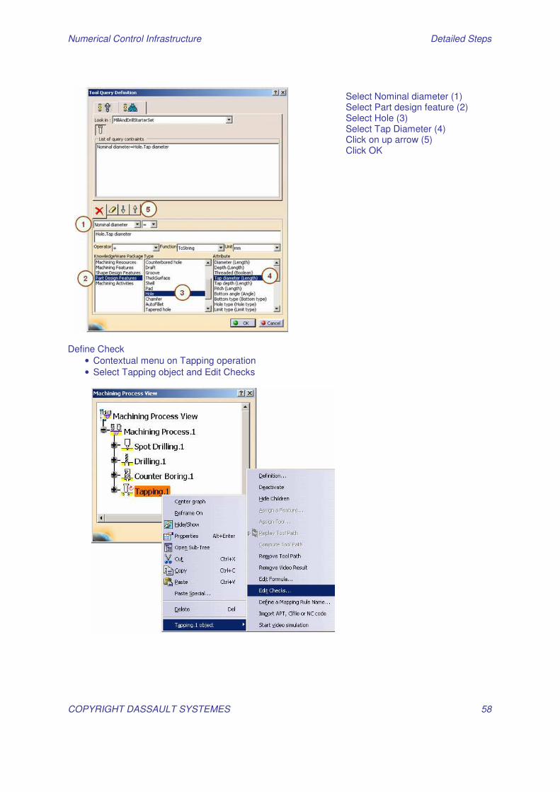
Define Check
• Contextual menu on Tapping operation • Select Tapping object and Edit Checks
Select Nominal diameter (1) Select Part design feature (2) Select Hole (3) Select Tap Diameter (4) Click on up arrow (5) Click OK
Numerical Control Infrastructure Detailed Steps
COPYRIGHT DASSAULT SYSTEMES 59
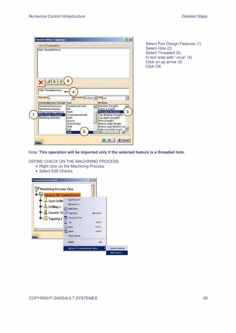
Note: This operation will be imported only if the selected feature is a threaded hole. DEFINE CHECK ON THE MACHINING PROCESS
• Right click on the Machining Process • Select Edit Checks
Select Part Design Features (1) Select Hole (2) Select Threaded (3) In text area add “=true” (4) Click on up arrow (5) Click OK
Numerical Control Infrastructure Detailed Steps
COPYRIGHT DASSAULT SYSTEMES 60
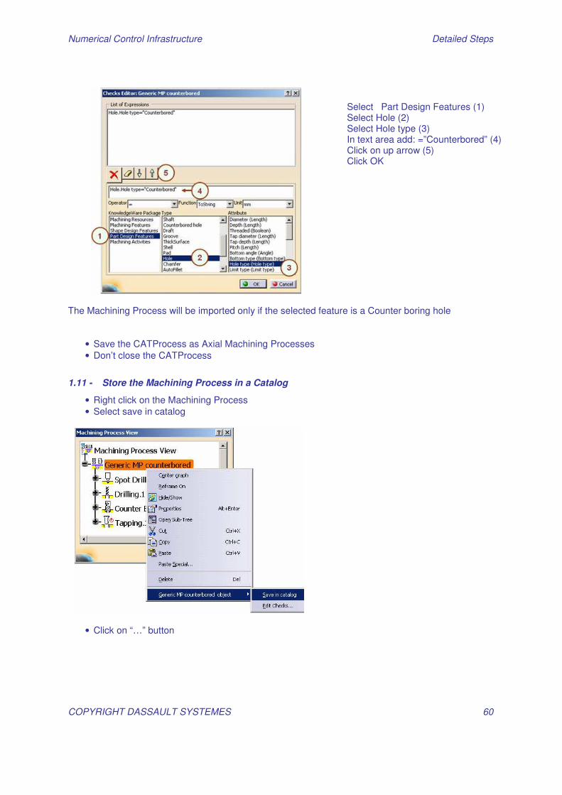
The Machining Process will be imported only if the selected feature is a Counter boring hole
• Save the CATProcess as Axial Machining Processes • Don’t close the CATProcess
1.11 - Store the Machining Process in a Catalog
• Right click on the Machining Process • Select save in catalog
• Click on “…” button
Select Part Design Features (1) Select Hole (2) Select Hole type (3) In text area add: =”Counterbored” (4) Click on up arrow (5) Click OK
Numerical Control Infrastructure Detailed Steps
COPYRIGHT DASSAULT SYSTEMES 61
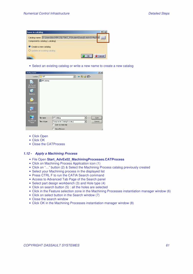
• Select an existing catalog or write a new name to create a new catalog
• Click Open • Click OK • Close the CATProcess
1.12 - Apply a Machining Process
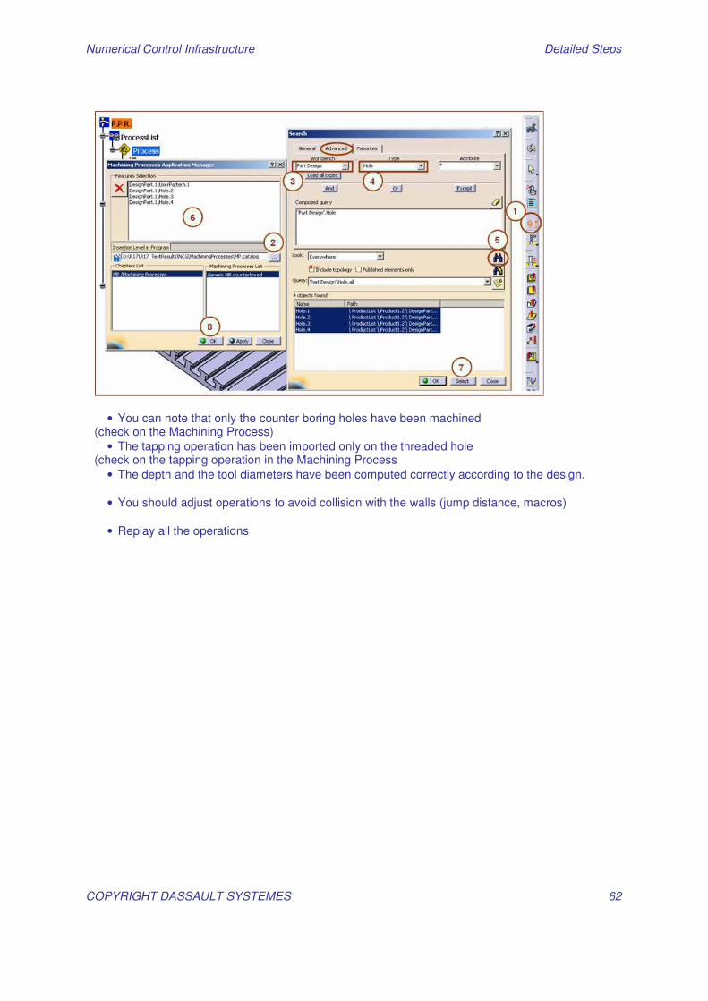
• File Open Start_AdvEx02_MachiningProcesses.CATProcess • Click on Machining Process Application icon (1) • Click on “…” button (2) & Select the Machining Process catalog previously created • Select your Machining process in the displayed list • Press CTRL F to run the CATIA Search command • Access to Advanced Tab Page of the Search panel • Select part design workbench (3) and Hole type (4) • Click on search button (5) : all the holes are selected • Click in the Feature selection zone in the Machining Processes instantiation manager window (6) • Click on select button in the Search window (7) • Close the search window • Click OK in the Machining Processes instantiation manager window (8)
Numerical Control Infrastructure Detailed Steps
COPYRIGHT DASSAULT SYSTEMES 62
• You can note that only the counter boring holes have been machined (check on the Machining Process)
• The tapping operation has been imported only on the threaded hole (check on the tapping operation in the Machining Process
• The depth and the tool diameters have been computed correctly according to the design.
• You should adjust operations to avoid collision with the walls (jump distance, macros)
• Replay all the operations
Numerical Control Infrastructure Detailed Steps
COPYRIGHT DASSAULT SYSTEMES 63
AdvEX 03: Manage Resources
1.13 - Create a new tool in your Catalog
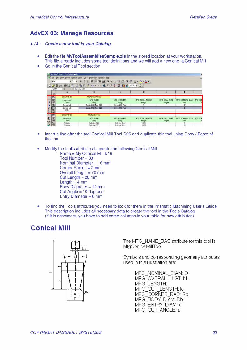
• Edit the file MyToolAssembliesSample.xls in the stored location at your workstation.
This file already includes some tool definitions and we will add a new one: a Conical Mill • Go in the Conical Tool section
• Insert a line after the tool Conical Mill Tool D25 and duplicate this tool using Copy / Paste of the line
• Modify the tool’s attributes to create the following Conical Mill:
Name = My Conical Mill D16 Tool Number = 30 Nominal Diameter = 16 mm Corner Radius = 2 mm Overall Length = 70 mm Cut Length = 20 mm Length = 4 mm Body Diameter = 12 mm Cut Angle = 10 degrees Entry Diameter = 6 mm
• To find the Tools attributes you need to look for them in the Prismatic Machining User’s Guide
This description includes all necessary data to create the tool in the Tools Catalog (If it is necessary, you have to add some columns in your table for new attributes)
Numerical Control Infrastructure Detailed Steps
COPYRIGHT DASSAULT SYSTEMES 64
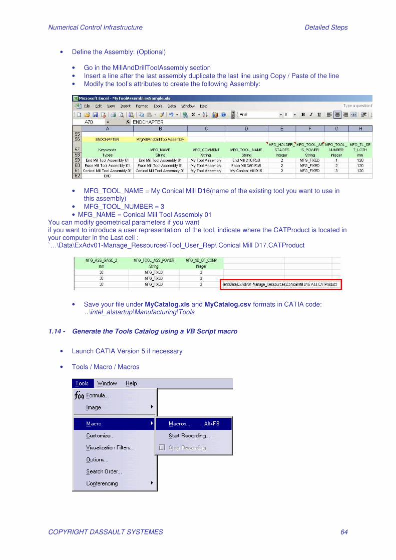
• Define the Assembly: (Optional)
• Go in the MillAndDrillToolAssembly section • Insert a line after the last assembly duplicate the last line using Copy / Paste of the line • Modify the tool’s attributes to create the following Assembly:
• MFG_TOOL_NAME = My Conical Mill D16(name of the existing tool you want to use in
this assembly) • MFG_TOOL_NUMBER = 3 • MFG_NAME = Conical Mill Tool Assembly 01
You can modify geometrical parameters if you want if you want to introduce a user representation of the tool, indicate where the CATProduct is located in your computer in the Last cell : …̀\Data\ExAdv01-Manage_Ressources\Tool_User_Rep\ Conical Mill D17.CATProduct
• Save your file under MyCatalog.xls and MyCatalog.csv formats in CATIA code: ..\intel_a\startup\Manufacturing\Tools
1.14 - Generate the Tools Catalog using a VB Script macro
• Launch CATIA Version 5 if necessary
• Tools / Macro / Macros
Numerical Control Infrastructure Detailed Steps
COPYRIGHT DASSAULT SYSTEMES 65
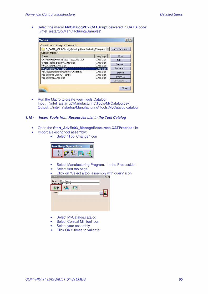
• Select the macro MyCatalogVB2.CATScript delivered in CATIA code: ..\intel_a\startup\Manufacturing\Samples\
• Run the Macro to create your Tools Catalog: Input: ..\intel_a\startup\Manufacturing\Tools\MyCatalog.csv Output: ..\intel_a\startup\Manufacturing\Tools\MyCatalog.catalog
1.15 - Insert Tools from Resources List in the Tool Catalog
• Open the Start_AdvEx03_ManageResources.CATProcess file • Import a existing tool assembly:
• Select “Tool Change” icon
• Select Manufacturing Program.1 in the ProcessList • Select first tab page • Click on “Select a tool assembly with query” icon
• Select MyCatalog.catalog • Select Conical Mill tool icon • Select your assembly • Click OK 2 times to validate

Numerical Control Infrastructure Detailed Steps
COPYRIGHT DASSAULT SYSTEMES 66
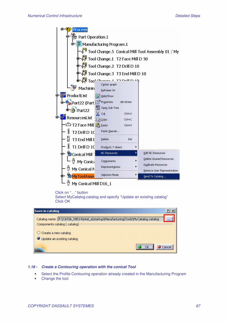
• Duplicate the tool: MB3 in the ResourcesList on the imported assembly & Select Duplicate Resources
• Modify the assembly (Name, parameter): Double click on the new assembly Name it MyToolAssembly
• Save the new assembly in the catalog: MB3 on the Assembly and select “Send To Catalog “
Numerical Control Infrastructure Detailed Steps
COPYRIGHT DASSAULT SYSTEMES 67
Click on “…” button Select MyCatalog.catalog and specify “Update an existing catalog” Click OK
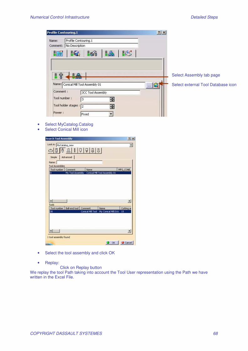
1.16 - Create a Contouring operation with the conical Tool
• Select the Profile Contouring operation already created in the Manufacturing Program • Change the tool
Numerical Control Infrastructure Detailed Steps
COPYRIGHT DASSAULT SYSTEMES 68
• Select MyCatalog.Catalog • Select Conical Mill icon
• Select the tool assembly and click OK
• Replay:
Click on Replay button We replay the tool Path taking into account the Tool User representation using the Path we have written in the Excel File.
Select Assembly tab page Select external Tool Database icon

Numerical Control Infrastructure Detailed Steps
COPYRIGHT DASSAULT SYSTEMES 69
• Right click on the conical tool assembly in the ResourceList • Select NC Resources / Remove user Representation
• Replay the tool path again

Numerical Control Infrastructure Detailed Steps
COPYRIGHT DASSAULT SYSTEMES 70
• Run video simulation
Numerical Control Infrastructure Detailed Steps
COPYRIGHT DASSAULT SYSTEMES 71
AdvEX 04: Auto Complete Open Start_AdvEx04_AutoComplete.CATProcess
1.17 - REPLAY:
Replay Machining Program
1.18 - ASSOCIATE DELMIA MACHINE:
• Associate DELMIA Machine (Necessary for AutoComplete functionality – not necessary to
have a DELMIA Licence) • Edit the PO • Access to Machine definition
• Click on ”Assign a machine from file selection” icon • Select Mill_5axis.CATProduct file from the folder at your workstation • Click Open • Click OK in the machine editor panel • Click OK In the PO panel
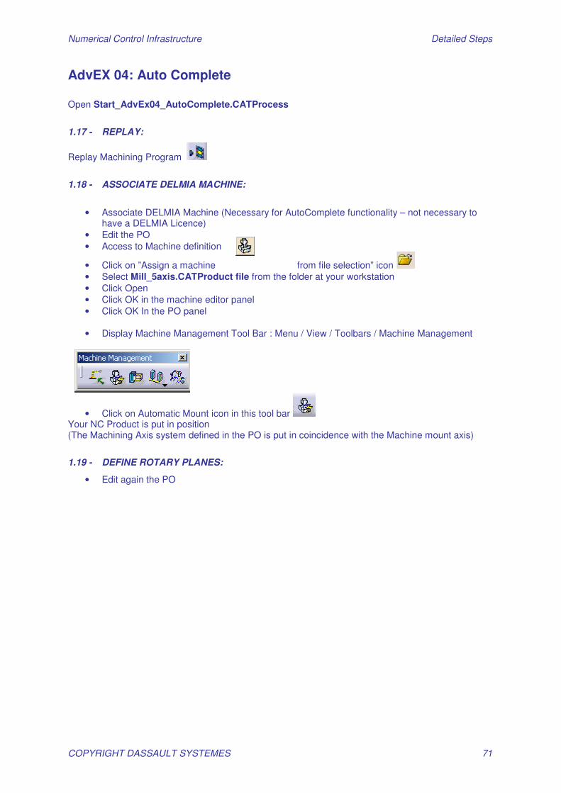
• Display Machine Management Tool Bar : Menu / View / Toolbars / Machine Management
• Click on Automatic Mount icon in this tool bar Your NC Product is put in position (The Machining Axis system defined in the PO is put in coincidence with the Machine mount axis)
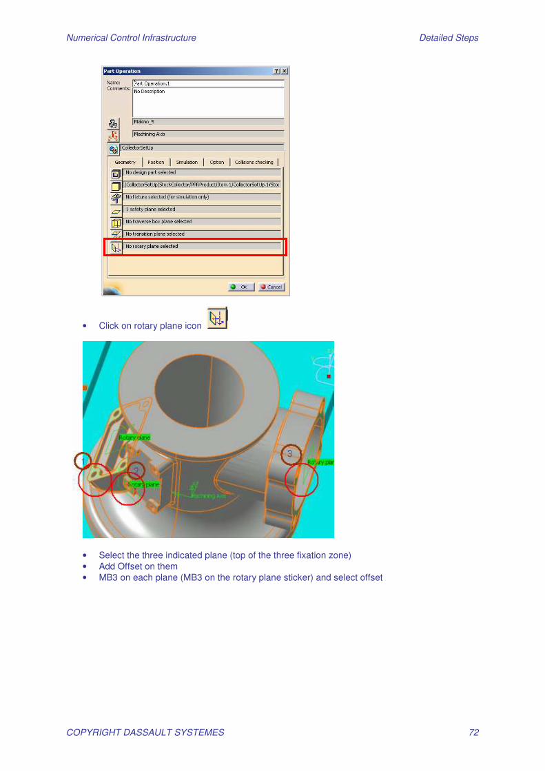
1.19 - DEFINE ROTARY PLANES:
• Edit again the PO
Numerical Control Infrastructure Detailed Steps
COPYRIGHT DASSAULT SYSTEMES 72
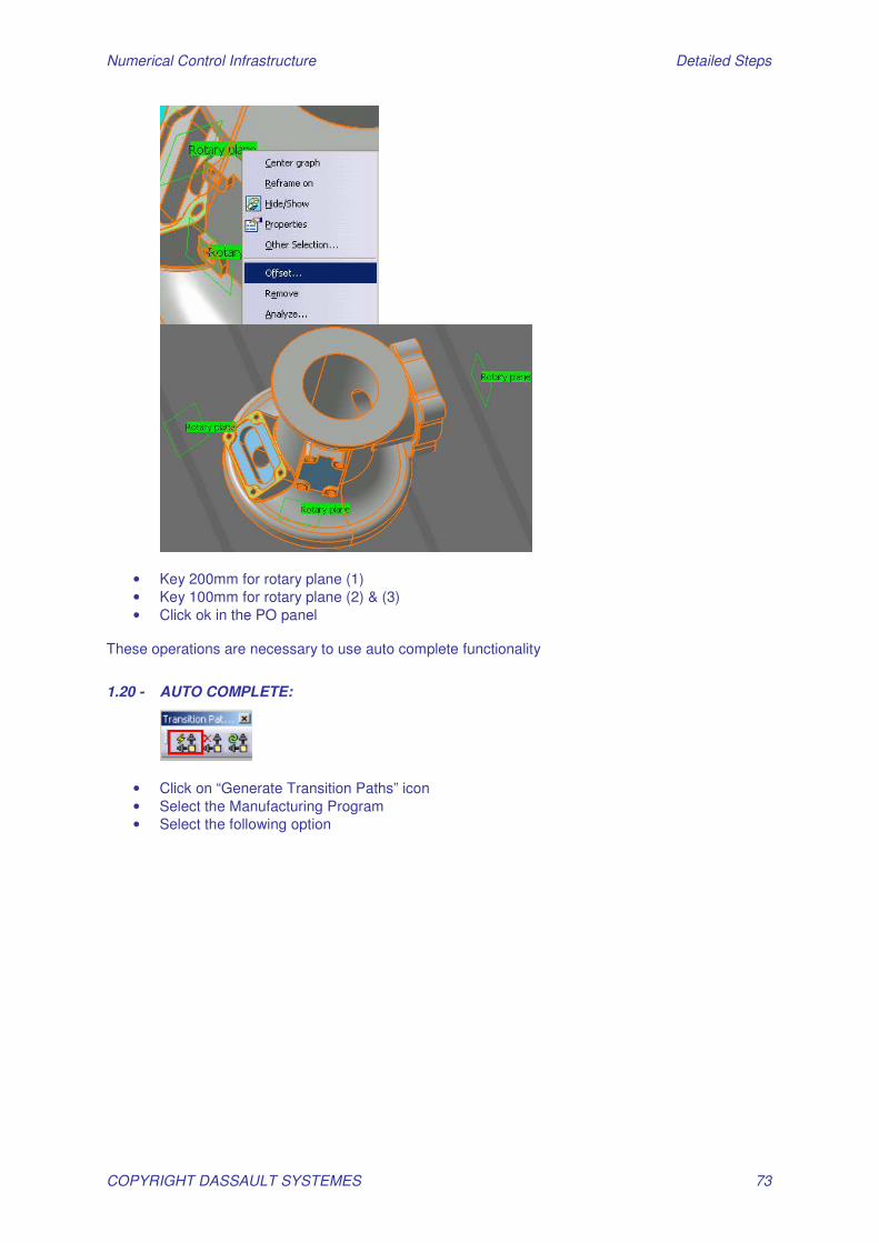
• Click on rotary plane icon
• Select the three indicated plane (top of the three fixation zone) • Add Offset on them • MB3 on each plane (MB3 on the rotary plane sticker) and select offset
Numerical Control Infrastructure Detailed Steps
COPYRIGHT DASSAULT SYSTEMES 73
• Key 200mm for rotary plane (1) • Key 100mm for rotary plane (2) & (3) • Click ok in the PO panel
These operations are necessary to use auto complete functionality
1.20 - AUTO COMPLETE:
• Click on “Generate Transition Paths” icon • Select the Manufacturing Program • Select the following option

Numerical Control Infrastructure Detailed Steps
COPYRIGHT DASSAULT SYSTEMES 74
It’s important to activate Compute axial-Radial motion because no transition planes have been defined in the PO
• Click OK • Expand PPR Tree to see added transition paths
1.21 - REPLAY & SIMULATE
• Select the Manufacturing Program
• Click on Replay icon
• See the tool path of all operation by using button
• At the last on click on Video icon to see Material removal simulation Note: You can also simulate machine tool motions with proper Licences.

Numerical Control Infrastructure Detailed Steps
COPYRIGHT DASSAULT SYSTEMES 75
AdvEX 05: PPWords Table Customization
1.22 - Create NC Program
Open Start_AdvEx05_PPWordTableCustmization.CATProcess Click on Drilling Dwell Delay icon
• Select the four holes to drill
• Click on replay • Click OK to end replay • Click OK to accept the operation • Save the CATProcess
1.23 - Generate APT code
• Select Manufacturing Program.1
Numerical Control Infrastructure Detailed Steps
COPYRIGHT DASSAULT SYSTEMES 76
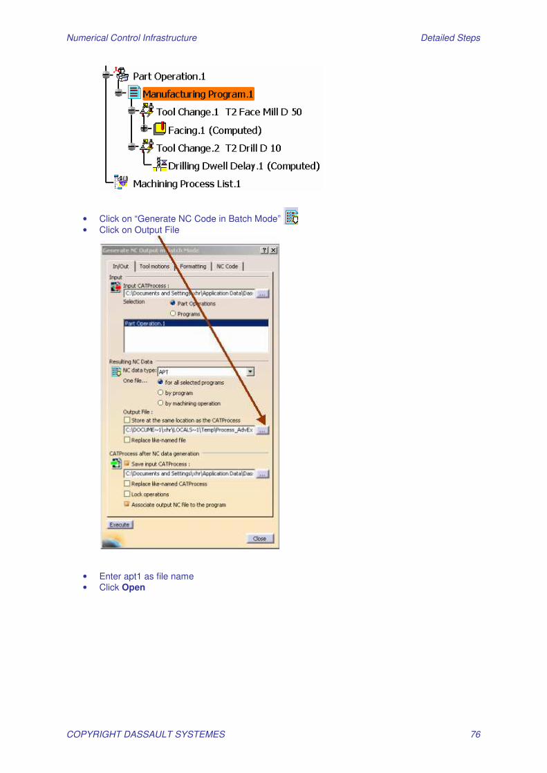
• Click on “Generate NC Code in Batch Mode” • Click on Output File
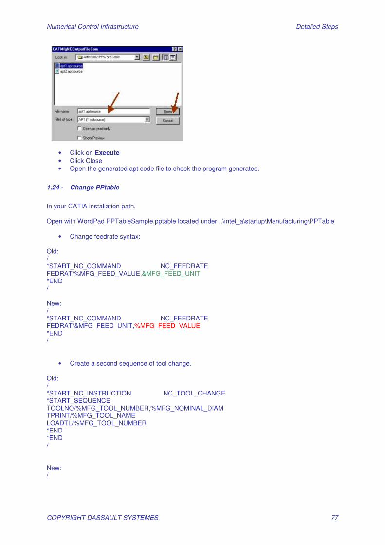
• Enter apt1 as file name • Click Open
Numerical Control Infrastructure Detailed Steps
COPYRIGHT DASSAULT SYSTEMES 77
• Click on Execute • Click Close • Open the generated apt code file to check the program generated.
1.24 - Change PPtable
In your CATIA installation path, Open with WordPad PPTableSample.pptable located under ..\intel_a\startup\Manufacturing\PPTable
• Change feedrate syntax: Old: / *START_NC_COMMAND NC_FEEDRATE FEDRAT/%MFG_FEED_VALUE,&MFG_FEED_UNIT *END / New: / *START_NC_COMMAND NC_FEEDRATE FEDRAT/&MFG_FEED_UNIT,%MFG_FEED_VALUE *END /
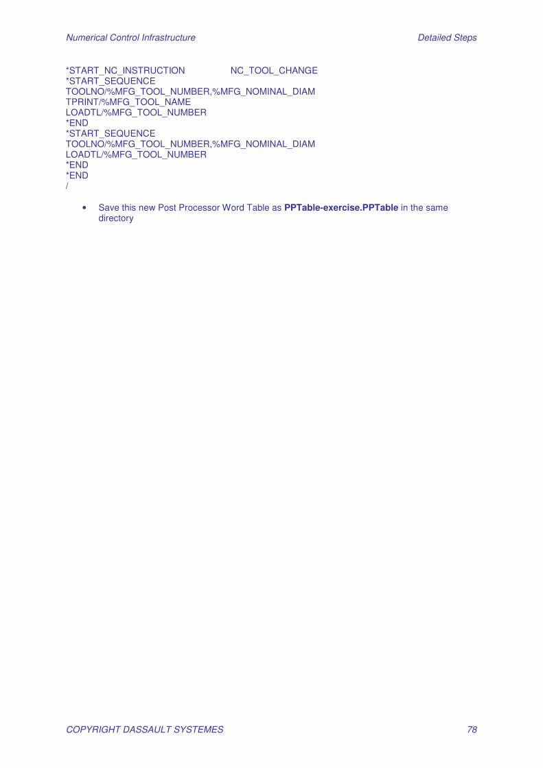
• Create a second sequence of tool change. Old: / *START_NC_INSTRUCTION NC_TOOL_CHANGE *START_SEQUENCE TOOLNO/%MFG_TOOL_NUMBER,%MFG_NOMINAL_DIAM TPRINT/%MFG_TOOL_NAME LOADTL/%MFG_TOOL_NUMBER *END *END / New: /
Numerical Control Infrastructure Detailed Steps
COPYRIGHT DASSAULT SYSTEMES 78
*START_NC_INSTRUCTION NC_TOOL_CHANGE *START_SEQUENCE TOOLNO/%MFG_TOOL_NUMBER,%MFG_NOMINAL_DIAM TPRINT/%MFG_TOOL_NAME LOADTL/%MFG_TOOL_NUMBER *END *START_SEQUENCE TOOLNO/%MFG_TOOL_NUMBER,%MFG_NOMINAL_DIAM LOADTL/%MFG_TOOL_NUMBER *END *END /
• Save this new Post Processor Word Table as PPTable-exercise.PPTable in the same directory
Numerical Control Infrastructure Detailed Steps
COPYRIGHT DASSAULT SYSTEMES 79
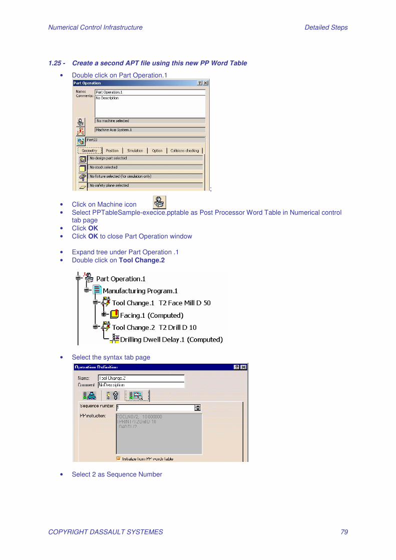
1.25 - Create a second APT file using this new PP Word Table
• Double click on Part Operation.1
;
• Click on Machine icon • Select PPTableSample-execice.pptable as Post Processor Word Table in Numerical control
tab page • Click OK • Click OK to close Part Operation window
• Expand tree under Part Operation .1 • Double click on Tool Change.2
• Select the syntax tab page
• Select 2 as Sequence Number
Numerical Control Infrastructure Detailed Steps
COPYRIGHT DASSAULT SYSTEMES 80
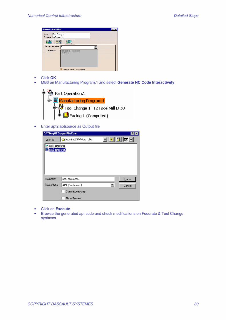
• Click OK • MB3 on Manufacturing Program.1 and select Generate NC Code Interactively
• Enter apt2.aptsource as Output file
• Click on Execute • Browse the generated apt code and check modifications on Feedrate & Tool Change
syntaxes.
Numerical Control Infrastructure Detailed Steps
COPYRIGHT DASSAULT SYSTEMES 81
AdvEX 06: Design Change Open Start_AdvEx06_DesignAssociativity.CATProcess Goto Prismatic Machining Workbench
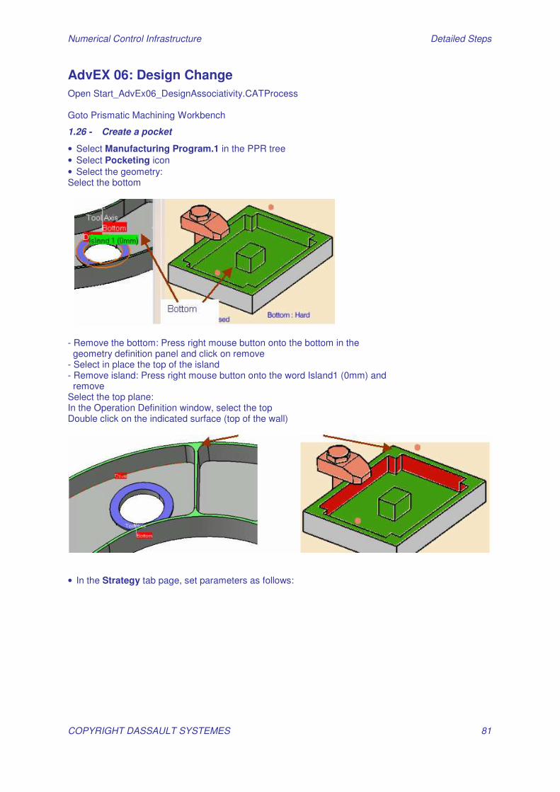
1.26 - Create a pocket
• Select Manufacturing Program.1 in the PPR tree • Select Pocketing icon • Select the geometry: Select the bottom
- Remove the bottom: Press right mouse button onto the bottom in the geometry definition panel and click on remove - Select in place the top of the island - Remove island: Press right mouse button onto the word Island1 (0mm) and remove Select the top plane: In the Operation Definition window, select the top Double click on the indicated surface (top of the wall)
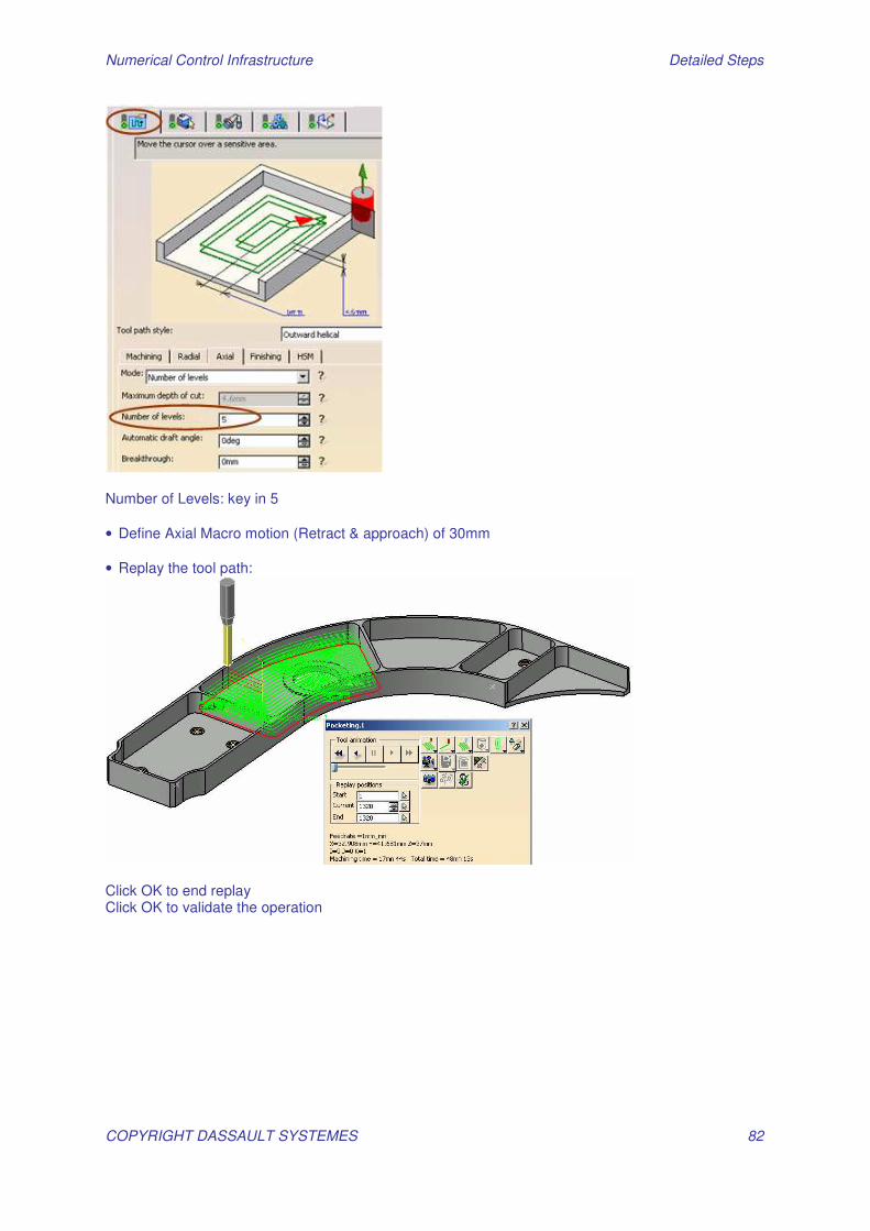
• In the Strategy tab page, set parameters as follows:
Numerical Control Infrastructure Detailed Steps
COPYRIGHT DASSAULT SYSTEMES 82
Number of Levels: key in 5 • Define Axial Macro motion (Retract & approach) of 30mm • Replay the tool path:
Click OK to end replay Click OK to validate the operation
Numerical Control Infrastructure Detailed Steps
COPYRIGHT DASSAULT SYSTEMES 83
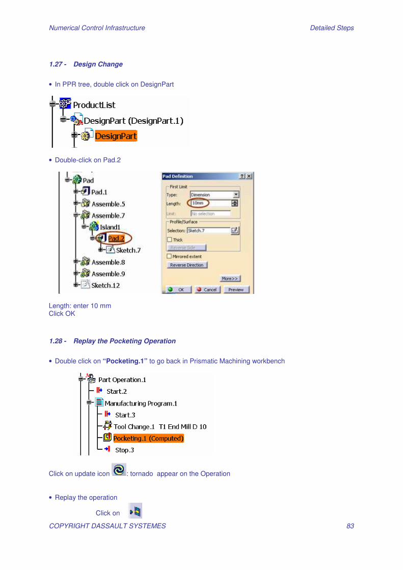
1.27 - Design Change
• In PPR tree, double click on DesignPart
• Double-click on Pad.2
Length: enter 10 mm Click OK
1.28 - Replay the Pocketing Operation
• Double click on “Pocketing.1” to go back in Prismatic Machining workbench
Click on update icon : tornado appear on the Operation • Replay the operation Click on
Numerical Control Infrastructure Detailed Steps
COPYRIGHT DASSAULT SYSTEMES 84
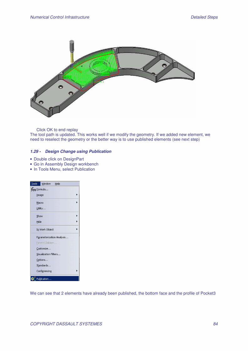
Click OK to end replay The tool path is updated. This works well if we modify the geometry. If we added new element, we need to reselect the geometry or the better way is to use published elements (see next step)
1.29 - Design Change using Publication
• Double click on DesignPart • Go in Assembly Design workbench • In Tools Menu, select Publication
We can see that 2 elements have already been published, the bottom face and the profile of Pocket3
Numerical Control Infrastructure Detailed Steps
COPYRIGHT DASSAULT SYSTEMES 85
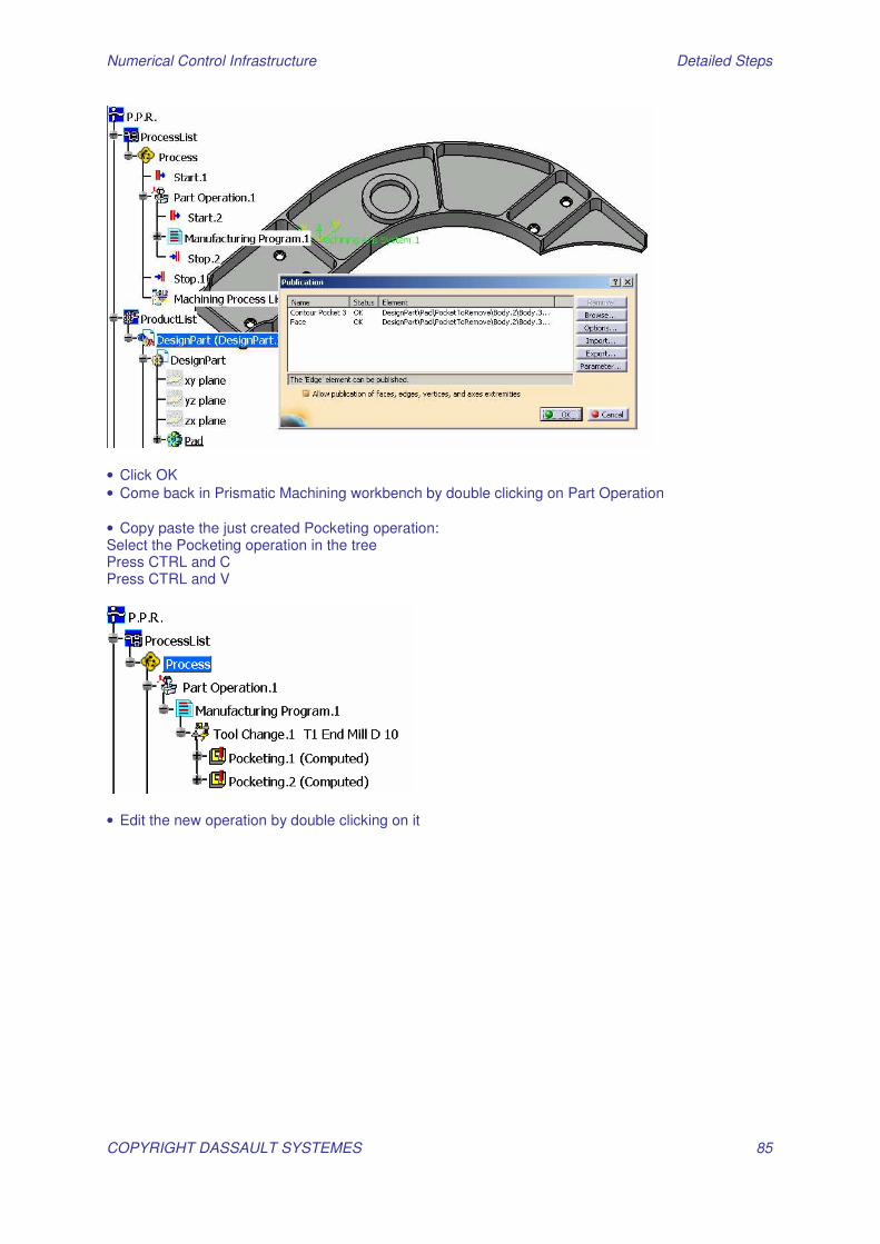
• Click OK • Come back in Prismatic Machining workbench by double clicking on Part Operation • Copy paste the just created Pocketing operation: Select the Pocketing operation in the tree Press CTRL and C Press CTRL and V
• Edit the new operation by double clicking on it
Numerical Control Infrastructure Detailed Steps
COPYRIGHT DASSAULT SYSTEMES 86
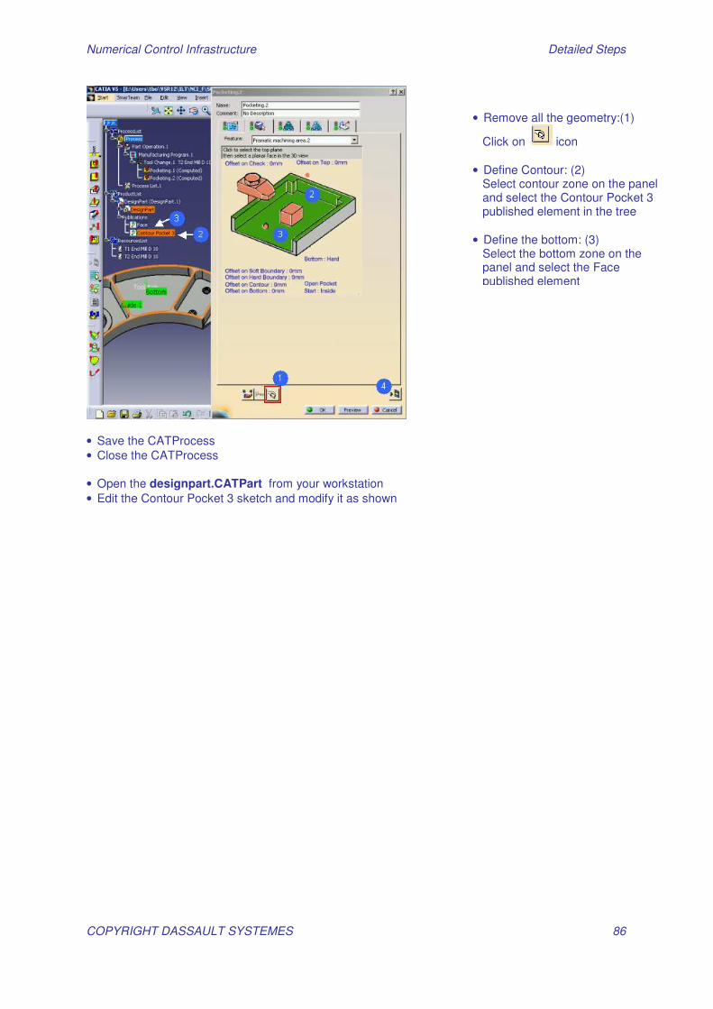
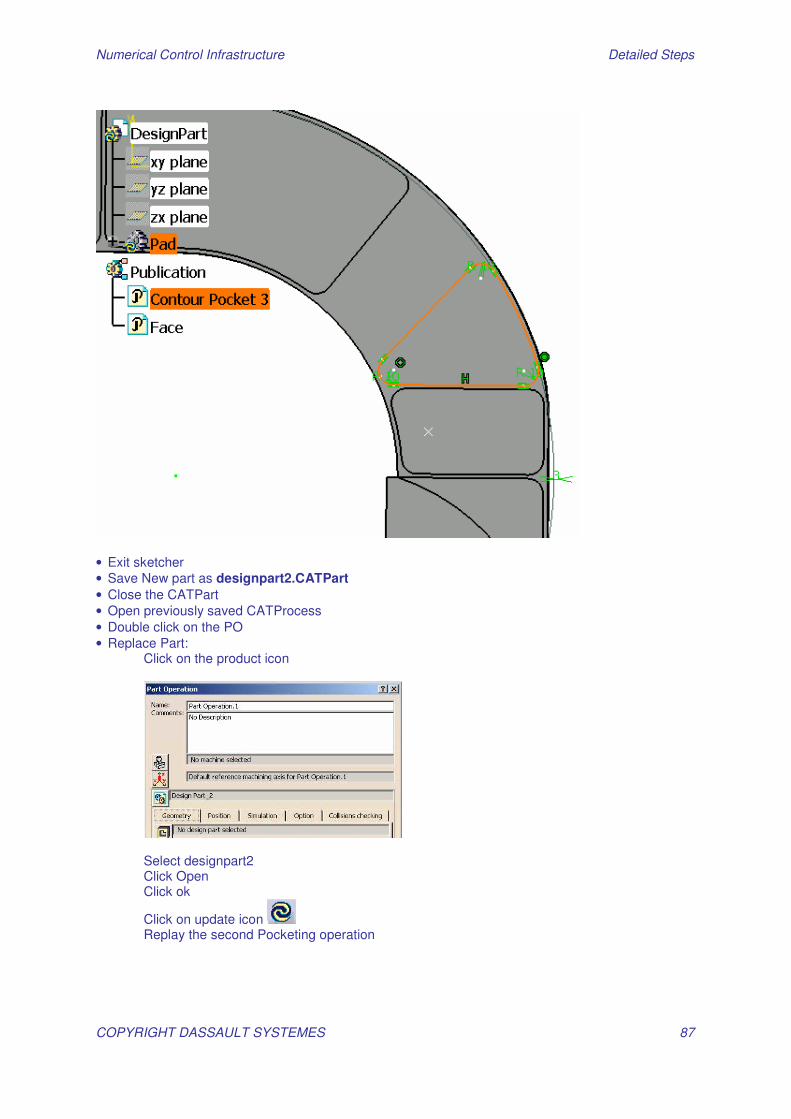
• Save the CATProcess • Close the CATProcess • Open the designpart.CATPart from your workstation • Edit the Contour Pocket 3 sketch and modify it as shown
• Remove all the geometry:(1)
Click on icon • Define Contour: (2) Select contour zone on the panel and select the Contour Pocket 3 published element in the tree • Define the bottom: (3) Select the bottom zone on the panel and select the Face published element
Numerical Control Infrastructure Detailed Steps
COPYRIGHT DASSAULT SYSTEMES 87
• Exit sketcher • Save New part as designpart2.CATPart • Close the CATPart • Open previously saved CATProcess • Double click on the PO • Replace Part:
Click on the product icon
Select designpart2 Click Open Click ok
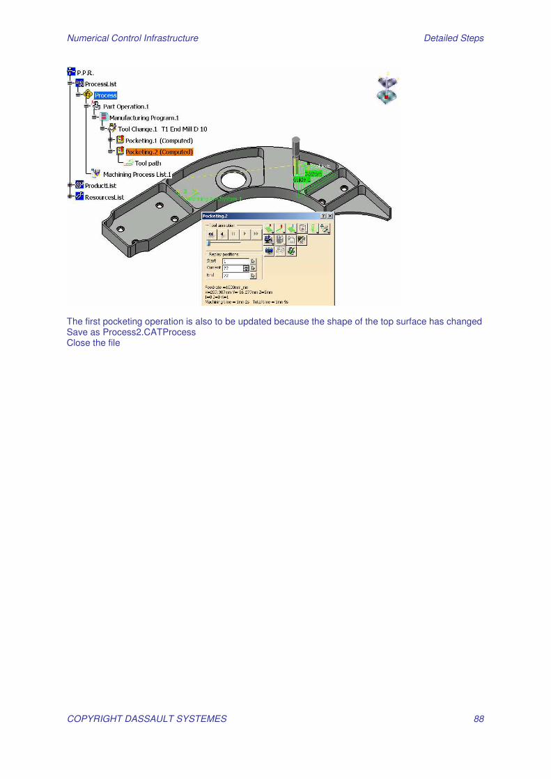
Click on update icon Replay the second Pocketing operation
Numerical Control Infrastructure Detailed Steps
COPYRIGHT DASSAULT SYSTEMES 88
The first pocketing operation is also to be updated because the shape of the top surface has changed Save as Process2.CATProcess Close the file