numerical calculations of rve dimensions for...
TRANSCRIPT

Journal of KONES Powertrain and Transport, Vol. 18, No. 2 2011
NUMERICAL CALCULATIONS OF RVE DIMENSIONS FOR TWO-PHASE MATERIAL
Danuta Miedzi ska, Tadeusz Niezgoda
Military University of Technology
Department of Mechanics and Applied Computer Science Gen. S. Kaliskiego Str. 2, 00-908 Warsaw, Poland
phone: +48 22 6837096, +48 22 6839461, fax: +48 22 6839355 e-mail: [email protected], [email protected]
Abstract
A representative volume element (RVE) is a statistical representation of typical material properties. It should contain enough information on the microstructure thereby be sufficiently smaller than the macroscopic structural dimensions.
The paper deals with the numerical calculations of the dimensions of the RVE for a two-phase material microstructure. Two and three dimensional models are taken into consideration. The structure of the samples are developed on the base of randomization of elements belonging to one of the phases. The phases volume share is 50/50%. The following series of the models are analyzed: from 10 x 10 to 100 x 100 elements for 2D samples and from 10 x 10 x 10 to 100 x 100 x 100 elements for 3D samples. The element characteristic dimension is 10 μm. The elastic behavior of the base materials (magnesium and alumina) is taken into account. The quasi-static compression tests of the developed structures are carried out with the use of LS-DYNA computer code. The results are presented as the equivalent Young modulus values and compared to the calculations based on the rule of mixtures. The stabilization of the achieved results allows to assess the dimensions of the RVE for two-phase material with random distribution.
Keywords: microstructure, two-phase material, metal-ceramic composite, RVE 1. Introduction
Modern ceramic materials are currently the most often subject of materials science research because of their special properties, such as low relative weight, high hardness, specific damage mechanism (micro cracks propagation). These properties influence the energy absorbing and dispersion capabilities, that can be increased by using foamed materials, especially the ones with an open-cell structure, that can be infiltrated with other material (metal or elastomer). They are so called hybrid materials.
The manufacturing processes of those materials usually consist of the following three steps: - Lay-up and fixation of the fibers, shaped as the desired component, - Introduction of the matrix material, - Final machining and, if required, further treatments like coating or generation of porosity.
In step one the fibers, often named rovings, are arranged and fixed using techniques applied in fiber-reinforced plastic materials, such as lay-up of fabrics, filament winding, braiding and knotting. The result of this procedure is called fiber-preform or simply preform. The third and final step of machining has to be done with diamond tools: grinding, drilling, lapping or milling. The special properties of the describe materials also allow to cut them with a water jet or a laser. For the second step, five different procedures are used to fill the ceramic matrix in between the fibers of the preform: - Deposition out of a gas mixture, - Pyrolysis of a pre-ceramic polymer, - Chemical reaction of elements,

D. Miedzi ska, T. Niezgoda
- Sintering at low temperatures (1000 to 1200°C), - Electrophoretic deposition of a ceramic powder.
The fifth procedure is not yet established in industrial processes. All procedures have sub-variations, which differ in technical details. Combinations of these procedures are also possible and applied.
The paper deals with the numerical calculations of the dimensions of the RVE for such two-phase material microstructure. 2. Two –phase materials modeling methods
The numerical models of materials and constructions allow to analyze complex phenomena, to
assess the material properties, micro- and macrostructural strength behavior, energy absorbing capabilities. The simulations for static and dynamic processes with consideration of large deformations, contact, damage processes, heat transfer, strain rate effects are possible.
Various techniques and methods are used for the purposes of numerical modeling of foamed and composite materials. Numerical models may be developed on the base of the real structure image e.g. 2D photograph (Fig. 1) or 3D scan (Fig. 2). The 3D scans are obtained by use of X-ray or neutron tomography technique. Models may have a smooth shape or may be based on a grid technique. Idealized models are also often used for investigations of influence of particular geometrical or material parameters onto global properties of foam. They may be built on the base of geometrical solids (i.e. Kelvin’s polyhedron) [7], composition of different polyhedrons, Weaire-Phelan 8-cell repeatable structure [1] or on the way of Voronoi 3D tessellation [4]. Idealized models may represent multi cell structures or may be reduced to repeatable fragment of geometry – single cell or its part, so they are convenient for fast comparative analysis of long series of differentiated models.
Fig. 1. Geometry of two-phase material real structure built on base of 2D photo [5]
The phenomenological models of materials may represent different levels of idealization. They
are useful for the research of the structure geometry influence on properties of materials. The models can be two or three dimensional (Fig. 3 and 4).
Fig. 2. Geometry of foamed material real structure built on base of 3D scan [3]
304
Numerical Calculations of RVE Dimensions for Two-Phase Material
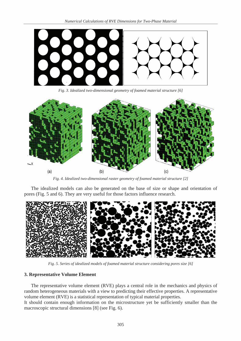
Fig. 3. Idealized two-dimensional geometry of foamed material structure [6]
Fig. 4. Idealized two-dimensional raster geometry of foamed material structure [2]
The idealized models can also be generated on the base of size or shape and orientation of
pores (Fig. 5 and 6). They are very useful for those factors influence research.
Fig. 5. Series of idealized models of foamed material structure considering pores size [6]
3. Representative Volume Element
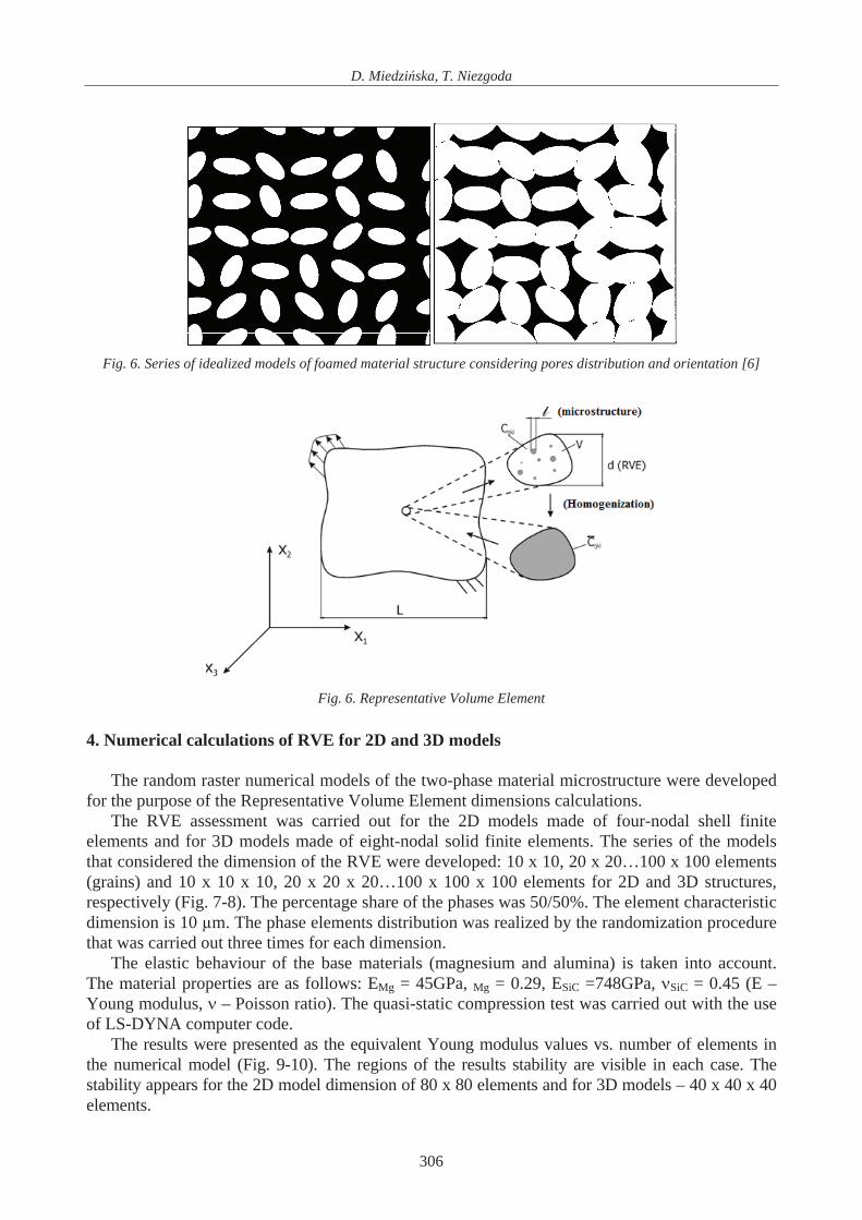
The representative volume element (RVE) plays a central role in the mechanics and physics of
random heterogeneous materials with a view to predicting their effective properties. A representative volume element (RVE) is a statistical representation of typical material properties. It should contain enough information on the microstructure yet be sufficiently smaller than the macroscopic structural dimensions [8] (see Fig. 6).
305
D. Miedzi ska, T. Niezgoda
Fig. 6. Series of idealized models of foamed material structure considering pores distribution and orientation [6]
Fig. 6. Representative Volume Element
4. Numerical calculations of RVE for 2D and 3D models
The random raster numerical models of the two-phase material microstructure were developed
for the purpose of the Representative Volume Element dimensions calculations. The RVE assessment was carried out for the 2D models made of four-nodal shell finite
elements and for 3D models made of eight-nodal solid finite elements. The series of the models that considered the dimension of the RVE were developed: 10 x 10, 20 x 20…100 x 100 elements (grains) and 10 x 10 x 10, 20 x 20 x 20…100 x 100 x 100 elements for 2D and 3D structures, respectively (Fig. 7-8). The percentage share of the phases was 50/50%. The element characteristic dimension is 10 μm. The phase elements distribution was realized by the randomization procedure that was carried out three times for each dimension.
The elastic behaviour of the base materials (magnesium and alumina) is taken into account. The material properties are as follows: EMg = 45GPa, Mg = 0.29, ESiC =748GPa, SiC = 0.45 (E – Young modulus, – Poisson ratio). The quasi-static compression test was carried out with the use of LS-DYNA computer code.
The results were presented as the equivalent Young modulus values vs. number of elements in the numerical model (Fig. 9-10). The regions of the results stability are visible in each case. The stability appears for the 2D model dimension of 80 x 80 elements and for 3D models – 40 x 40 x 40 elements.
306

Numerical Calculations of RVE Dimensions for Two-Phase Material
10x10 elements 20x20 elements 30x30 elements 40x40 elements 50x50 elements
60x60 elements 70x70 elements 80x80 elements 90x90 elements 100x100 elements
Fig. 7. Series of 2D models that consider the dimension of two-phase material RVE
The results presented above were compared to each other and with the results calculated on the
base of the rule of mixtures, what is shown in Fig. 11. The rule of mixtures allows calculating the average properties of the agglomerate in
accordance to Eq. 1: (1)
where: W - analysed material property, Xi - fraction of phase i share, Wi - analysed material property for phase i.
It can be concluded that the values for 2D and 3D models are the same for the sample dimensions of 80 x 80 elements and 40 x 40 x 40 elements, respectively. In both cases these values are about 10 MPa lower than calculated from the rule of mixture.
5. Conclusions
The numerical calculations of the dimensions of the RVE for a two-phase material
microstructure were presented. Two and three dimensional models were taken into
,
307

D. Miedzi ska, T. Niezgoda
consideration. The structure of the samples was developed on the base of randomization of elements belonging to one of the phases. The phase's volume share was 50/50%. The following series of the models were analyzed: from 10 x 10 to 100 x 100 elements for 2D samples and from 10 x 10 x 10 to 100 x 100 x 100 elements for 3D samples. The element characteristic dimension was 10 μm. The elastic behaviour of the base materials (magnesium and alumina) was taken into account. The quasi-static compression tests of the developed structures were carried out with the use of LS-DYNA computer code. The results were presented as the equivalent Young modulus values and compared to the calculations based on the rule of mixtures. The stabilization of the achieved results allows to assess the dimensions of the RVE for two-phase material with random distribution. The choice of the model (2D or 3D) must be based on the computational capacity of the available computer and time of analyses (30% shorter for 2D models).
10x10x10 20x20x20 30x30x30 40x40x40 50x50x50 elements elements elements elements elements
60x60x60 70x70x70 80x80x80 90x90x90 100x100x100 elements elements elements elements elements
Fig. . Series of 3D mode der the dime sion of two-phase material RVE 8 ls that consi n
308

Numerical Calculations of RVE Dimensions for Two-Phase Material
Fig. 9. Equivalent Young modulus values vs. number of elements in 2D numerical model
Fig. 10. Equivalent Young modulus values vs. number of elements in 3D numerical m el od
Fig. 11. Comparison of equivalent Young modulus values vs. number of elements for 2D and 3D nu erical model and mfor rule of mixtures
309

D. Miedzi ska, T. Niezgoda
Refere
] Kutner, R., Sullivan, J. M., Comparing the Weaire-Phelan Equal-Volume Foam to Kelvin’s
van, S., Stochastic Modeling Of The Permeability
ska, D., Szymczyk, W., Numerical and experimental study of real foam microstructure
uctural FE Models
i, J., Modelowanie numeryczne mikrostruktury
mechanical models for graded composite materials:
M., Micromechanics Of Complex Three-Dimensional Microstructures,
etonu wywo anego korozj siarczanow ,
nces [1
Foam, pp. 71-80, Taylor & Francis, 1996. [2] Li, Y., LeBoeuf, E. J., Basu, P. K., Mahade
Of Randomly Generated Porous Media, Advances in Water Resources, Vol. 28, pp. 835-844, 2005.
[3] Miedzimodels, Journal of KONES, Vol. 17, No. 2, pp. 309-314, Warszawa 2010.
[4] Mishnaevsky, Jr L. L., Automatic Voxel-Based Generation Of 3D MicrostrAnd Its Application To The Damage Analysis Of Composites, Materials Science and Engineering: A, Vol. 407, pp. 11-23, 2005.
[5] Niezgoda, T., Szymczyk, W., Ma achowskceramiki, WNT, Warszawa 2005.
[6] Reiter, T., Dvorak, G. J., MicroII thermomechanical loading, Journal of the Mechanics and Physics of Solids, Vol. 46, pp. 1655-1673, 1998.
[7] Shan, Z., Gokhale, A. Acta Materialia, Vol. 49, pp. 2001-2015, 2001.
[8] W glewski, W., Modelowanie zniszczenia bRozprawa doktorska, Instytut Podstawowych Problemów Techniki PAN, Warszawa 2008.
310