numerical and experimental studies on circulation of
TRANSCRIPT

Instructions for use
Title Numerical and experimental studies on circulation of working fluid in liquid droplet radiator
Author(s) Totani, Tsuyoshi; Kodama, Takuya; Watanabe, Kensuke; Nanbu, Kota; Nagata, Harunori; Kudo, Isao
Citation Acta Astronautica, 59(1-5), 192-199https://doi.org/10.1016/j.actaastro.2006.02.034
Issue Date 2006-07
Doc URL http://hdl.handle.net/2115/14525
Type article (author version)
Note Space for Inspiration of Humankind, Selected Proceedings of the 56th International Astronautical Federation Congress,Fukuoka, Japan, 17-21 October 2005
File Information Fullpaper_short_hr.pdf
Hokkaido University Collection of Scholarly and Academic Papers : HUSCAP

1
IAC-05-C2.6.04
NUMERICAL AND EXPERIMENTAL STUDIES ON CIRCULATION OF WORKING FLUID IN
LIQUID DROPLET RADIATOR
Tsuyoshi Totani, Takuya Kodama, Kensuke Watanabe, Kota Nanbu, Harunori Nagata and Isao Kudo
Hokkaido University, Sapporo, Japan
E-mail: [email protected]
ABSTRACT
A model of the circulation of the working fluid in a liquid droplet radiator has been developed. The model is
based on Bernoulli's law and the loss of the hydraulic head. The behavior of the circulation of the working
fluid calculated from the model is compared with that obtained from experiments in the case that the flow rate
of the circulating working fluid is changed. In radiators, the flow rate of the circulating working fluid is
changed in order to match the change of the waste heat generated in large-space structures. The flow rates of
the circulating working fluid calculated from the model correspond to those obtained from the experiments
well. The circulation mechanism of the working fluid in the liquid droplet radiator has been clarified. The
model developed in the present work will allow us to control the flow rate of the working fluid in the liquid
droplet radiator automatically.
INTRODUCTION
Disposing large quantities of waste heat is one of the
technical issues that must be considered in order to
realize large-space structures (LSSs) that handle
high power (from megawatt to gigawatt order) such
as space solar power satellites (SPSs).1,2 The liquid
droplet radiator (LDR) is an important candidate for
resolving this issue. Its lightweight structure, high
resistance to meteorite impacts, small storage
volume requirement at launch and easy deployment
in space make it a very attractive heat removal
system for the LSSs.
The operation of an LDR is schematically shown in
Fig. 1. The LDR, which consists of a droplet
generator, a droplet collector, a circulating pump, a
bellows-type pressure regulator (an accumulator)
and a heat exchanger, circulates the working fluid as
follows: The working fluid is heated through a heat
Fig. 1: Schematic diagram of liquid droplet radiator
Radiation
Circulatingpump
Accumulator
Space Structure
DropletGenerator
Droplet Streams
SpaceHeat
Exchanger
DropletCollector

2
exchanger by the waste heat generated in an LSS.
Then, the working fluid is emitted into space
through nozzles of the droplet generator toward a
droplet collector as tiny liquid droplets. During the
transport in space from the droplet generator to the
droplet collector, the droplets lose thermal energy
via radiative heat transfer. After the cooled
droplets are captured by the droplet collector, the
working fluid is recycled through the accumulator to
the heat exchanger by a circulating pump.
Liquids with low vapor pressures are candidates for
the working fluids from the viewpoint of minimizing
evaporation loss. In the cases of the waste heat
temperature range of 250 K - 350 K, of 370 K - 650
K and 500 K - 1000 K, silicone oils, liquid metal
eutectics and liquid tin are candidates, respectively.3
The surface radiating waste heat is the surface of
droplets in LDRs. Because LDRs do not require
solid bodies to protect the radiating surface from
punctures by small particles such as debris or small
meteorites, they are lightweight, stored in a small
volume at launch and easily deployed in orbit.4
Taussig and Mattick4 reported that LDRs can be as
much as 5 to 10 times lighter than advanced heat
pipe radiators. Massardo et al.5 reported that the
specific mass of a solar power dynamic system with
an LDR is 27% less than that with a conventional
heat pipe radiator. Droplet generation experiments
and droplet collection experiments on earth have
been conducted at the NASA Glenn Research Center
and the National Institute of Advanced Industrial
Science and Technology in Japan.6-9 Droplet
generation experiments and droplet collection
experiments under microgravity using drop-shafts
have been carried out by the authors.10, 11
LDRs change the flow rate of the circulating
working fluid in order to correspond to the change in
the amount of the waste heat removed from LSSs.
The numbers of revolutions of the droplet collector
and circulating pump, and the pressure applied on
the bellows-type pressure regulator, are controlled in
order to change the flow rate of the circulating
working fluid. However, few studies have been
carried out on controlling the flow rate of the
circulating working fluid in the LDR. It has not
been clarified how the flow rate of the circulating
working fluid in the LDR is controlled.
In this study, a model of the circulation of the
working fluid in the LDR is developed. The
behavior of the circulation of the working fluid
calculated from the model is compared with that
obtained from experiments in the case that the flow
rate of the circulating working fluid is changed.
EXPERIMENTAL & MODEL
Figure 2 shows a schematic diagram of the
experimental setup. Figure 3 shows a photograph
of the experimental setup. The working fluid flows
in the order of ①②③④⑤⑥⑦①, as indicated in
Fig. 2. The volume of the working fluid in the
droplet collector ② and the bellows-type pressure
regulator ⑤ can change. Two flowmeters ④
and ⑥ are set between ② and ⑤. In the case
that the flow rate at ④ is greater than that at ⑥,
the volume of the working fluid corresponding to the
difference of the flow rates is supplied from ② and
stored in ⑤. In the case that the flow rate at ⑥ is
greater than that at ④, the working fluid is supplied
from ⑤ and is pooled in ②.

3
Droplet generator
Figure 4 shows a schematic diagram of the droplet
generator. The working fluid, which is pressurized
by a bellows-type pressure regulator, is subjected to
a pressure disturbance using a piezoelectric vibrator
in the droplet generator and then is emitted in the
vacuum chamber ⑭ through a single nozzle, as
shown in Fig. 4. The pressure disturbance
produces radial variation on the surface of the
cylindrical jet-shaped working fluid. The
amplitude of this radial variation increases under
certain conditions.12-14 This increase in radial
variation causes the working fluid to break up from a
jet into tiny droplets. The transformation from a jet
to droplets is schematically illustrated in Fig. 4.
The velocity u1 of the working fluid at the exit of the
droplet generator is obtained using
QD
u2
21
4π
= , (1)
where Q is the circulation rate of the working fluid
in LDR.
Details of the nozzle in the droplet generator are
shown in Fig. 5. Considering the friction loss in
D1
D2L 1
L 2
Point 1
Point 2
Point 3
x
l 1
l 2Fig. 5: Details of nozzle in droplet generator
Fig. 4: Schematic diagram of droplet generator
Pressurizedworking fluid
Piezoelectricvibrator
Dropletstream
F
41 PPP −=∆
Nozzle1P
4P
Fig. 3: Experimental setup
GearPumpDroplet
Collector
DropletGenerator
Bellows-typePressureRegulator
VacuumChamber
Servomotor
Fig. 2: Schematic diagram of experimental setup
35°
①
③
④
⑤
⑥⑦ ⑧
⑨
⑩
⑪
⑫
⑬
⑭
⑮⑯ ②
⑰
①Droplet Generator②Droplet Collector③Gear Pump④⑥Flow Meter⑤Bellows-type Pressure Regulator
⑦Filter⑧Vacuum Pump⑨⑩Servomotor⑪N
2 Cylinder
⑫⑬Digital Indicator⑭Vacuum Chamber
Gas flow
Circulation Course of Working FluidVacuum Line
Pressure GaugeThermocouple
1
2 3
4
5
7 8a
b
⑮⑯Regulator⑰Valve
6

4
the nozzle Hgf, the pressure loss in the entrance
length of the nozzle Hge and the pressure loss at the
inlet of the nozzle Hgi, the head loss at the droplet generator gH is shown as
gigegfg HHHH ++= . (2)
The velocity in the nozzle ug changes with the
position x in the nozzle because the sectional area of
the nozzle changes with position x. The friction
loss in the nozzle Hgf is shown with the flow rate Q
as
gu
DLH g
gf 2
2
λ=
( )
+
−−
= 42
23
13
221
1 113
128Dl
DDDDl
gQ
ρπµ , (3)
where D1 (=1.2×10⁻³ m) and D2 (=4.0×10⁻⁴ m) are
the diameters of the nozzle, as shown in Fig. 5. l1
(=5.66×10⁻⁴ m) and l2 (=4.0×10⁻⁴ m) are the lengths of the nozzle. µ is the viscosity of the
working fluid. Because the Reynolds number in
the vinyl tube is sufficiently small, the flow is
regarded as laminar and the Darcy friction factor is
given by15
uDρµλ 64
Re64
== . (4)
The pressure loss in the entrance length of the nozzle
Hge is expressed as
gu
LLH g
egege 2
2
ζ=
( )
+
−−
= 42
23
13
221
1 1123
2Dl
DDDDl
gaQi
ρπµζ
, (5)
where Le is the entrance length of the nozzle, which
is given by16 DaLe Re= , a is the coefficient of the
entrance length (=0.065), and iζ is the coefficient
of pressure loss in the entrance length (= 2.7).16
The pressure loss at the inlet of the nozzle Hgi is
given as
42
2
228
2 DgQ
gu
H ig
igi πζζ == , (6)
where iζ is the coefficient of loss at the inlet (=
0.25).15
Droplet collector
The centrifugal collector shown in Fig. 6 has been
adopted in this study. The centrifugal collector
captures incident droplets at the liquid film inside
the spinning cone. The liquid film is formed
because incident droplets migrate radially outward
due to centrifugal force. The working fluid flows
out through stationary pitot tubes immersed in a
rotating liquid pool. The working fluid is pushed
out by the pressure produced by the centrifugal force
and momentum generated by the rotation of the
spinning cone.
The streamlines of stable flow in the rotating body
are concentric circles on the plane vertical to the
rotation axis. As shown in Fig. 7, a pitot tube
resides in the rotating working fluid in this droplet
collector. The wake flow is generated downstream
of the pitot tube. In the case of the centrifugal
collectors with small circumferences, the entrance of
the pitot tube could be located in the wake flow. In
this case, ue and Pe are shown as,17
602 frcrcu eee πω ⋅=⋅= , (7)
( )222
4 602
21
iee rrfcPP −
⋅+= πρ , (8)
where the constant c is a value specific to the shape
and arrangement of the centrifugal collector and the
pitot tube (=0.86 in this study). re and ri are the

5
radii of the entrance of the pitot tube (=8.0×10⁻² m)
and the inner surface of the working fluid in the
droplet collector, respectively. ri is chosen in such
a way that the volume of the working fluid pressed
against the wall because of the rotation of the droplet
collector is equal to the volume of the working fluid
in the droplet collector (=7.3×10⁻² m).
Circulating pump
An SK1-213 gear pump (Shimadzu Corporation)
was adopted as the circulating pump in the present
work because it is small and can push out the
working fluid under a large pressure difference
between upstream and downstream of the gear pump.
A schematic diagram of the gear pump is shown in
Fig. 8. The working fluid is pushed out by the
revolution of the gears.
The flow rate that the SK1-213 gear pump
discharges is given as
( )2360PP
ANUQ gpth −−=
µ, (9)
where Uth is the theoretical discharge rate per
rotation of the gears (=1 ml/rev.) and N is the
revolution of the gears per minute. As shown in
Fig. 8, there is a clearance between each gear and
the outside case of the gear pump because of
self-lubrication and the rotation of the gear. The
second term on the right-hand side of Eq. (9)
indicates the flow rate of the working fluid returning
from downstream to upstream of the gear pump
through the clearance. Agp is a constant and
decreases as the number of revolutions decreases.
By transforming Eq. (9), the hydraulic head
generated at the gear pump ③ is obtained using
−−=
−=∆
6023 NUQ
AggPP
H thgp
gp ρµ
ρ, (10)
where g denotes the gravitational acceleration (=9.81 m/s2) and ρ is the density of the working fluid.
Fig. 7: Top-view schematic diagram of
centrifugal collector from top view
WorkingFluid
InnerSurface
Direction of Rotation
wrer
ir
Pitot Tube
Wall of Collector
eP4P
Fig. 8: Schematic diagram of gear pump
2P 3P
Fig. 6: Schematic diagram of droplet collector
Droplet Stream
To Circulating PumpPitot Tube
Brim

6
Bellows-type pressure regulator
The bellows-type pressure regulator has functions of
pressurizing the working fluid and flow equalization.
The structure of ⑤ is shown in Fig. 9. ⑤ has a
bellows that contains the working fluid. The
working fluid is pressurized using nitrogen gas from
outside of the bellows. The bellows contributes to
preventing the working fluid from absorbing the
pressurized nitrogen gas. The bellows has a
characteristic of a spring. Considering the spring
force of the bellows and the pressure of gas outside
the bellows, the pressure of the working fluid in ⑤
is given as
b
nA
zzkPP
)(65
−+= , (11)
where k is the spring contact of the bellows (= 3.12
N/mm) and Ab is the area of the bottom lid of the
bellows (=1.86×10⁻² m2). z is the length of the
bellows and zn is the natural length of the bellows. z
is calculated from the difference between the flow
rate of inflow to the bellows Q4 and the flow rate of
outflow from the bellows Q6 using
( )bA
tQQzz
∆−+= 64
0 , (12)
where z0 denotes the length of the bellows t∆
seconds ago.
Filter
A filter is used to remove particles such as dust from
the working fluid. Particles such as dust cause the
blockade in the nozzle of the droplet generator. An
SS-4F-15 filter (Swagelok Company), in which there
is a sintered metal element with a nominal gap size
of 15 µm, is adopted in this study.
Flow meter
The volume of the working fluid could change in the
droplet collector and bellows-type pressure regulator
during circulation experiments on the working fluid.
Two flowmeters are set between ② and ⑤, and
between ⑤ and ②, as shown in Fig. 3. OVAL
M-III LSF41C0-M2 (OVAL corporation), which is a
displacement meter, is adopted in the flowmeters.
A YS02C strainer, with a net mesh gap of 77 µm, is
set upstream of the flow meter to remove particles
such as dust.
Piping
The hydraulic head lost from the exit of ⑤ to the
exit of the droplet generator ① 15−∆H is shown as
g
bel
Hg
ug
ug
uD
Lg
uH
+++
++=∆ −−
22
22)4(
77
66
215
2
15
ζζ
λζζ, (13)
where D is the diameter of the piping (=4.35×10⁻³
m) and L5-1 is the length of the piping from ⑤ to
① (= 1.45 m). u, u6 and u7 are the velocity of the
working fluid in the piping and the average
velocities of the working fluid in ⑥ including a
strainer and in filter ⑦ , respectively. elζ and
Pk
P5
P6
PressurizedGas
To DropletGenerator
From CirculatingPump
Bellows(SpringConstant k)
Bottom Lid
Fig. 9: Bellows-type pressure regulator

7
bζ are the coefficients of loss at an elbow and a
bend. The coefficient of loss at the elbow is given
as18
986.02
sin2.052
sin0.946 42 =
=
θθζ +el , (14)
where ϑ is the angle of the bend (= 90°). The
coefficient of loss at the bend is given as18
412.02
847.1131.05.3
=
+=
bb r
Dζ , (15)
where br is the radius of curvature. The friction
loss in the piping is derived from Eq. (13) as
== −−
guf
gu
DL
uDgu
DL
2264
2
215
215
ρµλ . (16)
As shown in Eq. (16), the friction loss in the piping is a function of gu 2/ . The pressure losses at ⑥
including a strainer and ⑦ are caused by friction in
the strainer and the filter. The pressure losses at
⑥ including a strainer and ⑦ has been assumed to
be a function of gu 2/ , as shown in Eq. (16). 6ζ
and 7ζ are the coefficients of loss at ⑥ including
a strainer and ⑦, respectively. Values calculated
from experimental data obtained t∆ seconds ago
are substituted in 6ζ and 7ζ .
The hydraulic head lost 52−∆H from ② to the
entrance of ⑤ is shown as
gu
gu
DL
guH bel 222
)24( 44
252
2
52 ζλζζ +++=∆ −− ,
(17)
where L2-5 is the length of the piping from ② to ⑤
(= 2.3 m). u and u4 are the velocity of the working
fluid in the piping and the average velocity of the
working fluid in ④ including a strainer,
respectively. 4ζ is the coefficient of loss at ④
including a strainer. The value calculated from
experimental data obtained t∆ seconds ago is
substituted in 4ζ .
Working fluid
A commercially available silicone oil (Shin-Etsu
Chemical Co., Ltd., KF96-50cSt) is employed as the
working fluid.
Bernoulli’s law
Applying Bernoulli's law and taking the loss of the
hydraulic head into account between the exit of ⑤
and the exit of ①, we obtain
15154
215
25
22 −− ∆+∆++=+ Hhg
Pg
ug
Pg
uρρ
, (18)
where 1u and 5u are the velocities at the exit of
① and at the exit of ⑤, respectively. 4P and 5P
are the pressure in ⑭ and the pressure of working
fluid in ⑤. 15−∆h is the vertical interval between
the exit of ⑤ and the exit of ① (=0.30 m).
Applying Bernoulli's law and taking into account the
loss of the hydraulic head between ② and ⑤, we
obtain
52525
25
2
22 −− ∆+∆++=∆++ Hhg
Pg
uH
gP
gu
gpee
ρρ,
(19)
where u5 and P5 are the velocity and pressure at the
entrance of ⑤ . 52−∆h is the vertical interval
between the entrance of the pitot tube in ② and the
entrance of ⑤ (=0.17 m).
The velocities u4, u5, u6 and u7 are equal to the
velocity u because the diameter in ④, the diameter
of the piping at the exit of ⑤, the diameter in ⑥
and the diameter in ⑦ are represented by the
diameter D (=4.35×10⁻³ m) of the piping. The
flow rate Q and velocity u are related through
8
uD
Q4
2π= . (20)
Solving Eq. (18) for Q, the flow rate between the
exit of ⑤ and the exit of ①, namely the flow rate
of ⑥ Q6 is obtained. Solving Eq. (19) for Q, the
flow rate between ② and ⑤, namely the flow rate
of ④ Q4 is obtained. The pressures P4 and P6 are
unknown in these equations. Experimental data is
substituted at the pressure P4 and P6. The pressure
in ⑭ P4 correspond to the pressure in space. The
pressure of gas outside ⑤ P6 can be controlled.
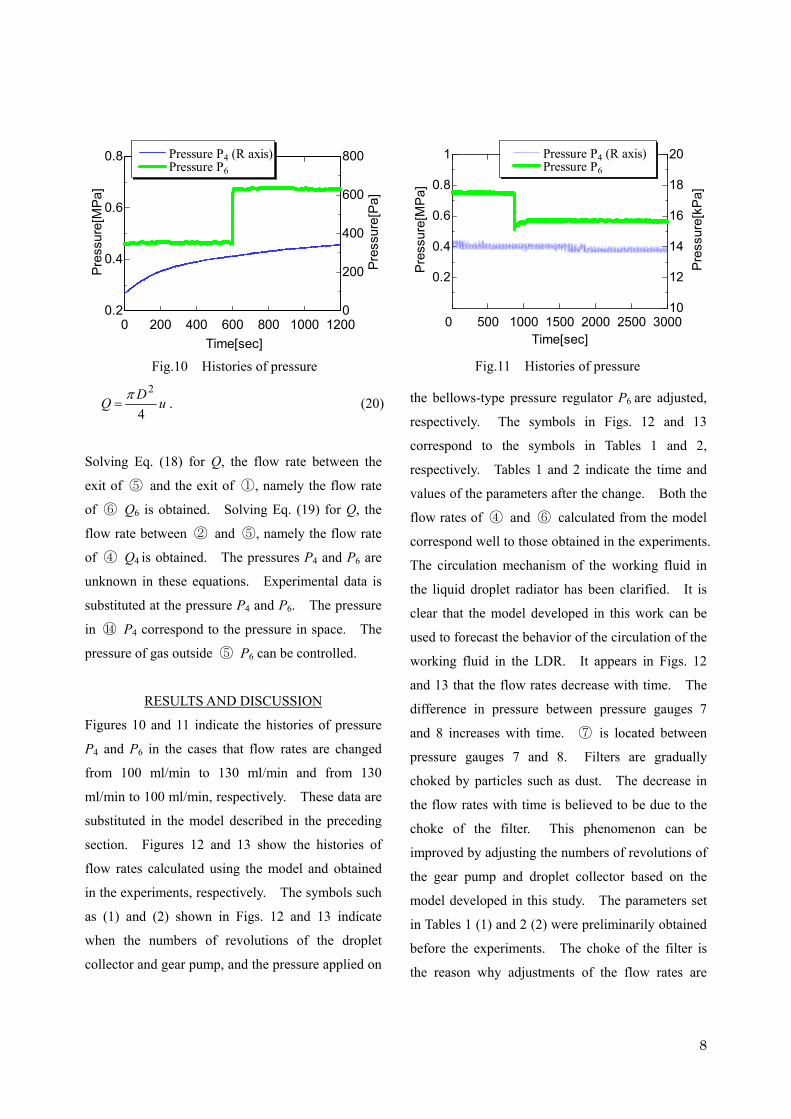
RESULTS AND DISCUSSION
Figures 10 and 11 indicate the histories of pressure
P4 and P6 in the cases that flow rates are changed
from 100 ml/min to 130 ml/min and from 130
ml/min to 100 ml/min, respectively. These data are
substituted in the model described in the preceding
section. Figures 12 and 13 show the histories of
flow rates calculated using the model and obtained
in the experiments, respectively. The symbols such
as (1) and (2) shown in Figs. 12 and 13 indicate
when the numbers of revolutions of the droplet
collector and gear pump, and the pressure applied on
the bellows-type pressure regulator P6 are adjusted,
respectively. The symbols in Figs. 12 and 13
correspond to the symbols in Tables 1 and 2,
respectively. Tables 1 and 2 indicate the time and
values of the parameters after the change. Both the
flow rates of ④ and ⑥ calculated from the model
correspond well to those obtained in the experiments.
The circulation mechanism of the working fluid in
the liquid droplet radiator has been clarified. It is
clear that the model developed in this work can be
used to forecast the behavior of the circulation of the
working fluid in the LDR. It appears in Figs. 12
and 13 that the flow rates decrease with time. The
difference in pressure between pressure gauges 7
and 8 increases with time. ⑦ is located between
pressure gauges 7 and 8. Filters are gradually
choked by particles such as dust. The decrease in
the flow rates with time is believed to be due to the
choke of the filter. This phenomenon can be
improved by adjusting the numbers of revolutions of
the gear pump and droplet collector based on the
model developed in this study. The parameters set
in Tables 1 (1) and 2 (2) were preliminarily obtained
before the experiments. The choke of the filter is
the reason why adjustments of the flow rates are
Fig.11 Histories of pressure
500 1000 1500 2000 2500 3000
0.2
0.4
0.6
0.8
1
10
12
14
16
18
20
0Time[sec]
Pre
ssur
e[M
Pa]
Pres
sure
[kP
a]
Pressure P4 (R axis) Pressure P6
0 200 400 600 800 1000 12000.2
0.4
0.6
0.8
0
200
400
600
800
Time[sec]
Pres
sure
[MPa
]
Pres
sure
[Pa]
Pressure P4 (R axis) Pressure P6
Fig.10 Histories of pressure

9
needed.
CONCLUSIONS
A model of the circulation of the working fluid in
the LDR has been developed. The flow rates of the
circulating working flow calculated from the model
correspond well to those obtained from the
experiments. The circulation mechanism of the
working fluid in the liquid droplet radiator has been
clarified. The model will allow us to control the
flow rate of the working fluid in the liquid droplet
radiator automatically.
ACKNOWLEDGEMENT
This study is carried out as part of “Ground-Based
Research Announcement for Space Utilization”
promoted by the Japan Space Forum.
REFERENCES
1. Glaser, P. E., “Power from the Sun: Its Future,”
Science, Vol. 162, 1968, p. 857.
2. Mankins, J. C., “A Fresh Look at Space Solar
Power: New Architectures, Concepts and
Technologies,” Acta Astronaoutica, Vol. 41,
Time
[sec]
Pressure
[MPa]
Rate of revolutions of
droplet collector [rpm]
Rate of revolutions
of gear pump [rpm]
- - 0.477 670 193
(1) 599 0.683 720 271
(2) 633 0.683 720 265
Table 1 Changes in parameters
Fig.12 Histories of flow rate

10
Nos. 4-10, 1997, pp. 347-359
3. Mattick, A. T. and Hertzberg, A., "Liquid
Droplet Radiators for Heat Rejection in Space,"
Journal of Energy, Vol. 5, No. 6, 1981, pp.
387-393
4. Taussig, R. T. and Mattick A. T., "Droplet
Radiator Systems for Spacecraft Thermal
Control,” Journal of Spacecraft and Rockets,
Vol. 23, No. 1, 1986, pp. 10-17
5. Massardo, A. F., Tagliafico, L. A., Fossa, M.
and Agazzani, A., "Solar Space Power System
Optimization with Ultralight Radiator," Journal
of Propulsion and Power, Vol. 13, No. 4, 1997,
pp. 560-564
6. Presler, A. F., Coles, C. E., Diem-Kirsop, P. S.
and White, K. A., "Liquid Droplet Radiator
Program at the NASA Lewis Research Center,"
ASME 86-HT-15, June 1986
7. White, K. A., "Liquid Droplet Radiator
Development Status," AIAA Paper 87-1537,
Table 2 Changes in parameters
Time
[sec]
Pressure
[MPa]
Rate of revolutions of
droplet collector [rpm]
Rate of revolutions
of gear pump [rpm]
0.756 800 283
(1) 865 0.570 670 283
(2) 879 0.570 670 202
(3) 901 0.570 670 217
(4) 990 0.570 670 220
(5) 1040 0.570 670 222
Fig.13 Histories of flow rate

11
June 1987
8. Hosokawa, S., Kawada, M., Iwasaki, A. and
Kudo, I., "Formation of a Uniform Liquid
Droplet Stream for a Liquid Droplet Radiator,"
Journal of the Japan Society for Aeronautical
and Space Sciences, Vol. 39, No. 453, 1991, pp.
551-557 (in Japanese)
9. Hosokawa, S., Kawada, M., Iwasaki, A. and
Kudo, I., "Observation of Collecting Process of
Liquid Droplets in Liquid Droplet Radiator,"
Journal of the Japan Society for Aeronautical
and Space Sciences, Vol. 41, No. 474, 1993, pp.
385-390 (in Japanese)
10. Totani, T., Itami, M., Yabuta, S., Nagata, H.,
Kudo, I., Iwasaki, A. and Hosokawa, S.,
"Performance of Droplet Emittor for Liquid
Droplet Radiator under Microgravity,"
Transactions of the Japan Society of
Mechanical Engineers B,” Vol. 68, No. 668,
2002, pp. 1166-1173 (in Japanese)
11. Totani, T., Itami, M., Nagata, H., Kudo, I.,
Iwasaki, A. and Hosokawa, S., "Performance of
Droplet Generator and Droplet Collector in
Liquid Droplet Radiator under Microgravity,"
Microgravity Science and Technology, Vol. 13,
No. 2, 2002, pp. 42-45
12. Rayleigh, L., “On the Instability of a Cylinder
of Viscous Liquid under Capillary Force.
Philosophical Magazine,” Vol. 34, 1892, pp.
130-145
13. Weber, C., “Zum Zerfall eines
Flüssigkeitsstrahles, Zeitschrift fuer
Angewandte Mathematik und Mechanik,” Vol.
11, 1931, pp.136-154
14. Chandrasekhar, “S., Hydrodynamic and
Hydromagnetic Stability,” Chap. XII, New
York, Dover Publications, Inc, 1981
15. F. M. White, Fluid Mechanics, 2nd ed. New
York, McGraw Hill, 1999, Chap. 6, 325-426
16. Kiso Ryutai Rikigaku Henshu Iinkai, Kiso
Ryutai Rikigaku, (Sangyou Tosho, Tokyo,
1989), Chap.6, 45-58 (in Japanese).
17. Totani, T., Itami, M., Nagata, H., Kudo, I. and
Iwasaki, A., ”Measurement technique for
pumping performance of a centrifugal collector
under microgravity”, Review of Scientific
Instruments, Vol. 75, No. 2, 2004, pp. 515-523
18. Kunikiyo, Y,, Kimoto, T., Nagao, K.,
“Suirikigaku”, Tokyo, Morikita Shuppan, 1971,
Chap. 5, pp. 124-140 (in Japanese)