numerical analysis of the mechanical behavior of welded i
TRANSCRIPT
Coupled Systems Mechanics, Vol. 8, No. 2 (2019) 185-197
DOI: https://doi.org/10.12989/csm.2019.8.2.185 185
Copyright © 2019 Techno-Press, Ltd. http://www.techno-press.org/?journal=csm&subpage=8 ISSN: 2234-2184 (Print), 2234-2192 (Online)
Numerical analysis of the mechanical behavior of welded I beam-to-RHS column connections
Rosicley J. R. Rosa* and Juliano G. R. Netoa
Department of Civil Engineering, Pontifical Catholic University of Goiás,
Av. Universitária 1.440, Setor Universitário, Goiânia, Goiás, Brazil
(Received September 26, 2018, Revised February 25, 2019, Accepted March 11, 2019)
Abstract. Considering the increasing use of tubular profiles in civil construction, this paper highlights the
study on the behavior of welded connections between square hollow section column and I-beam, with
emphasis on the assessment of the joint stiffness. Firstly, a theoretical analysis of the welded joints has been
done focusing on prescriptions of the technical literature for the types of geometries mentioned. Then, a
numerical analysis of the proposed joints were performed by the finite element method (FEM) with the
software ANSYS 16.0. In this study, two models were evaluated for different parameters, such as the
thickness of the cross section of the column and the sizes of cross section of the beams. The first model
describes a connection in which one beam is connected to the column in a unique bending plane, while the
second model describes a connection of two beams to the column in two bending planes. From the
numerical results, the bending moment-rotation (M-φ) curve was plotted in order to determine the resistant
bending moment and classify each connection according to its rotational capacity. Furthermore, an equation
was established with the aim of estimating the rotational stiffness of welded I beam-to-RHS column
connections, which can be used during the structure design. The results show that most of the connections
are semi-rigid, highlighting the importance of considering the stiffness of the connections in the structure
design.
Keywords: steel structures; hollow section column; welded connections; bending moment-rotation
1. Introduction
The increasing use of steel structures is associated with advantageous factors in relation to
reinforced concrete structures, highlighting: the upper productivity, the possibility of building
structures with longer spans using lighter elements, the high precision of the parts and joints of the
structures and the possibility of reusing.
The tubular sections (circular hollow sections CHS and rectangular hollow sections RHS,
including square ones) have been highlighted among the steel structures, because these sections
provide the most efficient use of a steel cross section in resisting compression, tension, bi-axial
bending and torsion (Lu 1997).
The growing demand for the hollow sections in civil construction is related to the several
Corresponding author, Undergraduate, E-mail: [email protected] aPh.D., E-mail: [email protected]
Rosicley J. R. Rosa and Juliano G. R. Neto
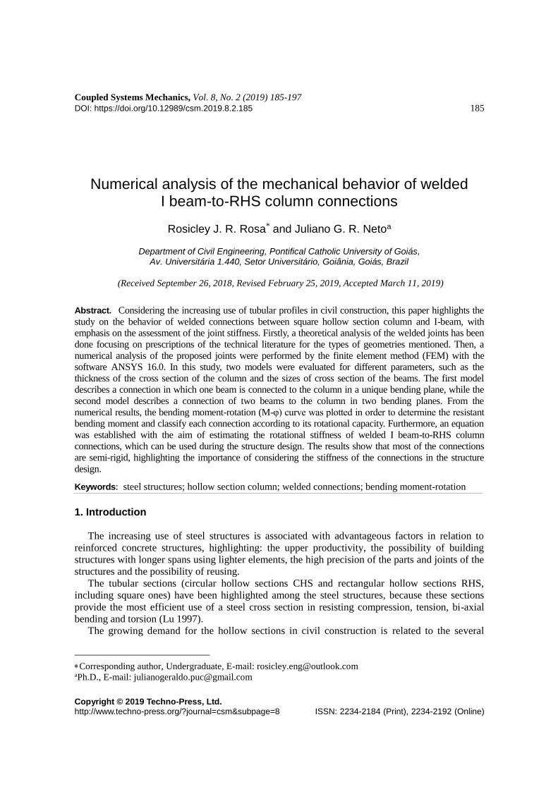
Fig. 1 Beam with various end conditions (adapted from CIDECT 2010)
possibilities of use; and according Matos et al (2015), this is justified basically due to their
mechanical and aesthetical characteristics. For example, the hollow section can be combined with
concrete, in order to increase the compressive strength and to provide fire protection. The Comité
International pour le Développement et l’Etude de la Construction Tubulaire (CIDECT 2010)
points out that the reinforced concrete filled hollow section columns without external fire
protection can reach a fire life of even 2 hours depending on the cross section ratio of the steel and
concrete.
Díaz et al. (2011) highlights that during the development of a structural project, it is necessary
to consider not only the capacity of the insulated elements, but also the structure as a whole.
Moreover, it is necessary to analyze the behavior of the joints between two or more profiles. In this
sense, Matos et al. (2015) comment that the available analytical formulations to predict the
behavior of hollow sections have been included in recent design codes, such as Eurocode 3 (EN
1993-1-8 2005) and, more recently, the Brazilian ABNT NBR 16239 (2013) code. Thus, the
elements must be chosen strategically, so that to develop a structural project with the adequate
joints and lower cost during the constructive process. In this sense, suitable and accurate design
methods plays and important role in design of systems which employs hollow sections because
they affect the cost and the safety of the structure as explained by Matos et al. (2015).
Machado (2013) states that the types of joint have a strong influence on the structural system,
since there are many ways to connect beams and columns. The joints are able to generate
geometric discontinuities, changing the linear behavior of the structure. In this research, the joints
between I-beams and square hollow section columns will be done through welding, because this
type of joint is simpler to represent the behavior of a rigid joint between sections of different
geometries.
According to Faridmehr et al. (2016), in analysis and design of steel frame structures, the
connections are considered in two extreme cases in relation to their mechanical behavior. One of
these extremes is known as rigid connection while the other one is referred to as pinned
connection. In the first, in case of bending moment resistant connections, there is no relative
rotation after the deformation of the structure. On the other hand, the pinned connections have
opposite behavior, because they do not restrict the relative rotation during the deformation process.
Nevertheless, as presented by Lozano et al (2018), the beam-column joints usually behave as
semi-rigid, which means the beam transmits bending moment to the column proportionally to its
186
Numerical analysis of the mechanical behavior of welded…
stiffness.
The semi-rigid connections enable the development of a structural design using slender sections
due to the lower design bending moment when compared to a rigid or pinned connection, as it can
be seen in Fig. 1. Nunes (2012, apud CIDECT 2010) states that the use of these connections in a
framed structure can reduce the cost from 10% to 20%.
Studies involving RHS columns and I-beams were presented by Lu (1997), CIDECT (2010),
Nunes (2012), Guerra et al. (2013), Wu and Feng (2013), Serrano-López et al. (2016), Eslami and
Namba (2016a), Eslami and Namba (2016b) among others. In order to continuing the studies on
the RHS steel connections, this paper reports the results of theoretical and numerical analysis of
welded joints. The theoretical analysis is based on the prescription of Lu (1997) and CIDECT
(2010). The numerical analysis of the joints was performed by the Finite Element Method (FEM)
with the software ANSYS 16.0.
This paper aims to study the mechanical behavior of uniplanar and multiplanar welded
connections between square hollow section column and I beam. It, specifically, aims to determine
the resistant bending moment, plot the M-φ curve and classify the connections according to its
rotational capacity. Since Eurocode 3 (EN 1993-1-8 2005) and CIDECT (2010) do not have a tool
to determine the connection stiffness, an equation was proposed to estimate the rotational stiffness
of welded I beam-to-RHS column connections, which enables the consideration of the connections
stiffness in the structure design, in order to obtain projects with lower costs.
2. Theoretical analysis
2.1 Stiffness classification of the connections
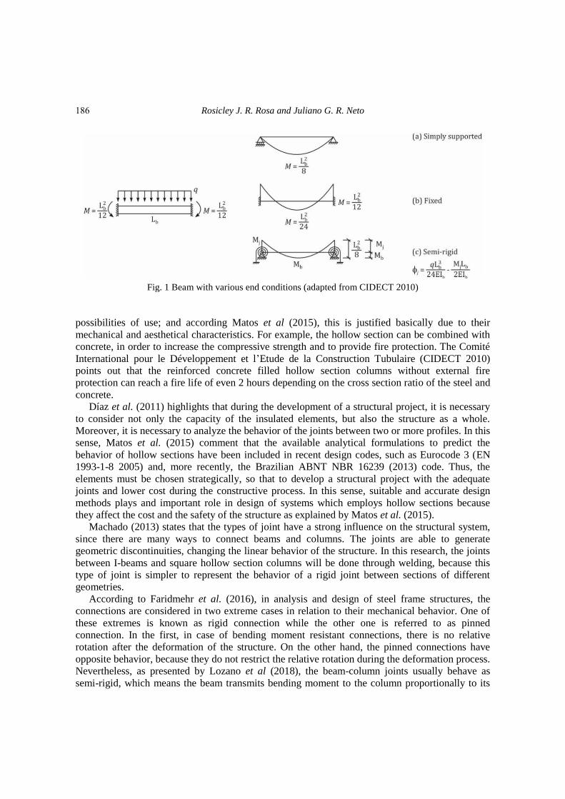
The moment-rotation curve indicates the behavior of the welded connections due to the
possibility to classify these connections and determine the resistant moment and the rotation
capacity. The joint stiffness is equivalent to the tangent in the linear stretch of the curve. In order
to classify the joints, Eurocode 3 (EN 1993-1-8 2005) provides stiffness classification, as shown in
Fig. 2, in which Sj,ini is the joint stiffness, E is the elasticity modulus of the steel, Ib and Lb are,
respectively, the moment of inertia and the length of the beam. In this study, the moment-rotation
is determined by numerical simulation using the software ANSYS 16.0.
Fig. 2 Limits for stiffness classification of beam-to-column joints for unbraced frames (adapted from
Eurocode 3-EN 1993-1-8 2005)
187

Rosicley J. R. Rosa and Juliano G. R. Neto
2.2 Failure mode
The CIDECT (2010) proposes seven failure modes involving welded I beam-to-RHS column
joints. The sizing of the connections is done according to the failure mode that it is subjected.
Furthermore, the failure modes, which must be considered for design, are: the local failure of the
beam flange, the column plastification (face, wall or cross section), the column punching shear and
the column shear failure. The failure mode predicted for the models of this research, as well as
predicted in the studies of Rocha and Neto (2016), is the column wall plastification, which is
represented by Eqs. (1) and (2) proposed respectively by CIDECT (2010) and Lu (1997) and
illustrated in Fig. 3.
M1,Rd = fy0t20 (
4
√1 − β) (h1 − t1) (1)
M1,Rd = fy0t20(h1 − t1) (
2
√1 − β+
1
2η+
η
1 − β) (2)
In Eqs. (1) and (2) M1,Rd is the design resistant bending moment, fy0 is the yield stress of the
RHS member, t0 is the wall thickness of the column, h1 is the depth of the I section, t1 is the flange
thickness of the I beam. In addition, the important geometric parameters (β, 2γ and η) are
presented in the following equations being b1 the width of the I-beam and b0 the width of the RHS
column.
β = b1
b0 (3)
2γ = b0
t0 (4)
η = h1
b0 (5)
Fig. 3 Column wall plastification (adapted from CIDECT 2010)
188
Numerical analysis of the mechanical behavior of welded…
3. Numerical analysis
The most suitable and accurate methodology to determine the connection behavior is through
experimental analysis, which is very expensive for design practices, being restricted only in
researches. So, to overcome this inconvenient, computational simulation can be performed to
predict the M-φ curve considering (as desirable) the non-linear behavior. In this study, numerical
analyses of uniplanar and multiplanar joints were carried out by the Finite Element Method (FEM)
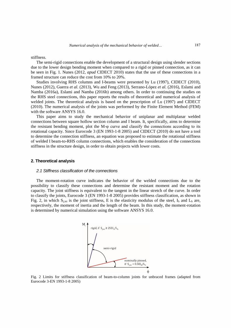
with the software ANSYS 16.0, as shown in Fig. 4.
(a) (b)
Fig. 4 Geometry and sizes of (a) uniplanar model; (b) multiplanar model. Units in mm
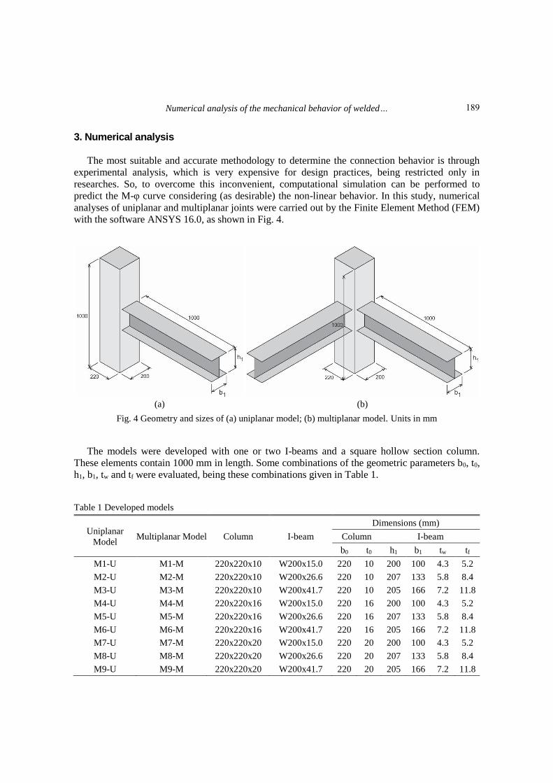
The models were developed with one or two I-beams and a square hollow section column.
These elements contain 1000 mm in length. Some combinations of the geometric parameters b0, t0,
h1, b1, tw and tf were evaluated, being these combinations given in Table 1.
Table 1 Developed models
Uniplanar
Model Multiplanar Model Column I-beam
Dimensions (mm)
Column I-beam
b0 t0 h1 b1 tw tf
M1-U M1-M 220x220x10 W200x15.0 220 10 200 100 4.3 5.2
M2-U M2-M 220x220x10 W200x26.6 220 10 207 133 5.8 8.4
M3-U M3-M 220x220x10 W200x41.7 220 10 205 166 7.2 11.8
M4-U M4-M 220x220x16 W200x15.0 220 16 200 100 4.3 5.2
M5-U M5-M 220x220x16 W200x26.6 220 16 207 133 5.8 8.4
M6-U M6-M 220x220x16 W200x41.7 220 16 205 166 7.2 11.8
M7-U M7-M 220x220x20 W200x15.0 220 20 200 100 4.3 5.2
M8-U M8-M 220x220x20 W200x26.6 220 20 207 133 5.8 8.4
M9-U M9-M 220x220x20 W200x41.7 220 20 205 166 7.2 11.8
189
Rosicley J. R. Rosa and Juliano G. R. Neto
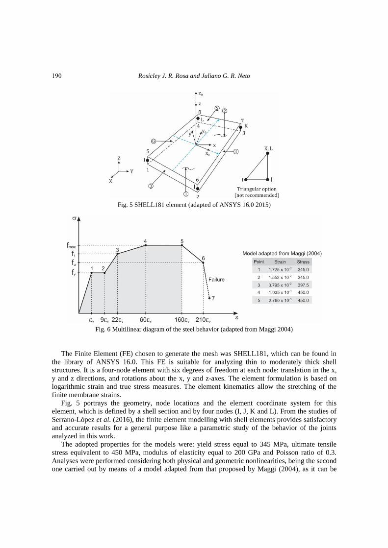
Fig. 5 SHELL181 element (adapted of ANSYS 16.0 2015)
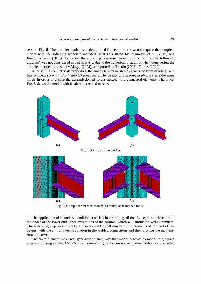
Fig. 6 Multilinear diagram of the steel behavior (adapted from Maggi 2004)
The Finite Element (FE) chosen to generate the mesh was SHELL181, which can be found in
the library of ANSYS 16.0. This FE is suitable for analyzing thin to moderately thick shell
structures. It is a four-node element with six degrees of freedom at each node: translation in the x,
y and z directions, and rotations about the x, y and z-axes. The element formulation is based on
logarithmic strain and true stress measures. The element kinematics allow the stretching of the
finite membrane strains.
Fig. 5 portrays the geometry, node locations and the element coordinate system for this
element, which is defined by a shell section and by four nodes (I, J, K and L). From the studies of
Serrano-López et al. (2016), the finite element modelling with shell elements provides satisfactory
and accurate results for a general purpose like a parametric study of the behavior of the joints
analyzed in this work.
The adopted properties for the models were: yield stress equal to 345 MPa, ultimate tensile
stress equivalent to 450 MPa, modulus of elasticity equal to 200 GPa and Poisson ratio of 0.3.
Analyses were performed considering both physical and geometric nonlinearities, being the second
one carried out by means of a model adapted from that proposed by Maggi (2004), as it can be
190
Numerical analysis of the mechanical behavior of welded…
seen in Fig. 6. The complex statically undetermined frame structures would require the complete
model with the softening response included, as it was stated by Imamovic et al. (2015) and
Imamovic et al. (2018). However, the softening response (from point 5 to 7 of the following
diagram) was not considered in this analysis, due to the numerical instability when considering the
complete model proposed by Maggi (2004), as reported by Tristão (2006), Freitas (2009).
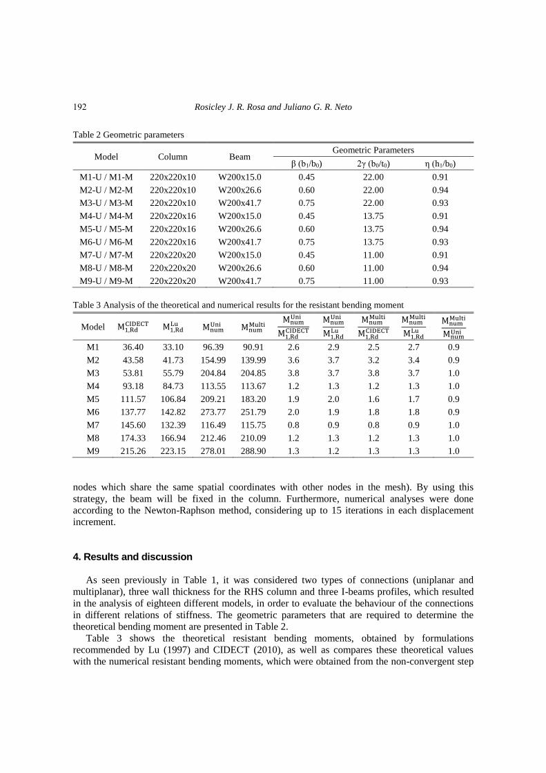
After setting the materials properties, the finite element mesh was generated from dividing each
line segment shown in Fig. 7 into 10 equal parts. The beam-column joint needed to share the same
mesh, in order to ensure the transmission of forces between the connected elements. Therefore,
Fig. 8 shows the model with its already created meshes.
(a) (b)
Fig. 7 Division of the meshes
(a) (b)
Fig. 8(a) uniplanar meshed model; (b) multiplanar meshed model
The application of boundary conditions consists in restricting all the six degrees of freedom in
the nodes of the lower and upper extremities of the column, which will simulate fixed extremities.
The following step was to apply a displacement of 50 mm in 100 increments at the end of the
beams, with the aim of causing rotation in the welded connections and then plotting the moment-
rotation curve.
The finite element mesh was generated in such way that model behaves as monolithic, which
implies in using of the ANSYS 16.0 command glue to remove redundant nodes (i.e., repeated
191
Rosicley J. R. Rosa and Juliano G. R. Neto
Table 2 Geometric parameters
Model Column Beam Geometric Parameters
β (b1/b0) 2γ (b0/t0) η (h1/b0)
M1-U / M1-M 220x220x10 W200x15.0 0.45 22.00 0.91
M2-U / M2-M 220x220x10 W200x26.6 0.60 22.00 0.94
M3-U / M3-M 220x220x10 W200x41.7 0.75 22.00 0.93
M4-U / M4-M 220x220x16 W200x15.0 0.45 13.75 0.91
M5-U / M5-M 220x220x16 W200x26.6 0.60 13.75 0.94
M6-U / M6-M 220x220x16 W200x41.7 0.75 13.75 0.93
M7-U / M7-M 220x220x20 W200x15.0 0.45 11.00 0.91
M8-U / M8-M 220x220x20 W200x26.6 0.60 11.00 0.94
M9-U / M9-M 220x220x20 W200x41.7 0.75 11.00 0.93
Table 3 Analysis of the theoretical and numerical results for the resistant bending moment
Model M1,RdCIDECT M1,Rd
Lu MnumUni Mnum
Multi Mnum
Uni
M1,RdCIDECT
MnumUni
M1,RdLu
MnumMulti
M1,RdCIDECT
MnumMulti
M1,RdLu
MnumMulti
MnumUni
M1 36.40 33.10 96.39 90.91 2.6 2.9 2.5 2.7 0.9
M2 43.58 41.73 154.99 139.99 3.6 3.7 3.2 3.4 0.9
M3 53.81 55.79 204.84 204.85 3.8 3.7 3.8 3.7 1.0
M4 93.18 84.73 113.55 113.67 1.2 1.3 1.2 1.3 1.0
M5 111.57 106.84 209.21 183.20 1.9 2.0 1.6 1.7 0.9
M6 137.77 142.82 273.77 251.79 2.0 1.9 1.8 1.8 0.9
M7 145.60 132.39 116.49 115.75 0.8 0.9 0.8 0.9 1.0
M8 174.33 166.94 212.46 210.09 1.2 1.3 1.2 1.3 1.0
M9 215.26 223.15 278.01 288.90 1.3 1.2 1.3 1.3 1.0
nodes which share the same spatial coordinates with other nodes in the mesh). By using this
strategy, the beam will be fixed in the column. Furthermore, numerical analyses were done
according to the Newton-Raphson method, considering up to 15 iterations in each displacement
increment.
4. Results and discussion
As seen previously in Table 1, it was considered two types of connections (uniplanar and
multiplanar), three wall thickness for the RHS column and three I-beams profiles, which resulted
in the analysis of eighteen different models, in order to evaluate the behaviour of the connections
in different relations of stiffness. The geometric parameters that are required to determine the
theoretical bending moment are presented in Table 2.
Table 3 shows the theoretical resistant bending moments, obtained by formulations
recommended by Lu (1997) and CIDECT (2010), as well as compares these theoretical values
with the numerical resistant bending moments, which were obtained from the non-convergent step
192

Numerical analysis of the mechanical behavior of welded…
of the computational processing of each model. This non-convergent step characterizes the
existence of regions of the models whose stresses reached the yielding stress. In the Table 3, MnumUni
and MnumMulti represent the numerical resistant bending moments of the uniplanar and multiplanar
models, respectively. In the same way, M1,RdCIDECT and M1,Rd
Lu are the design resistant bending
moment of the joints, which are established by CIDECT (2010) and Lu (1997), respectively.
It is observed from Table 3 that in the models formed by columns that have wall thickness of
10 mm, there was greater difference of the numerical results in relation to the analytical models of
Lu (1997) and CIDECT (2010). On the other hand, for the connections involving columns that
have wall thickness of 20 mm, there is greater similarity between these values. From the following
table, it is noticed that there is a small variation among the resistant bending moments of the
uniplanar and multiplanar models.
The ratios between numerical and theoretical resistant bending moment, illustrated in Table 3,
are similar to those obtained by Nunes (2012), except for the models of this study with wall
thickness of 10 mm. The studies of Nunes (2012) showed these ratios varying from 0.9 to 1.6.
The computational simulation was performed with the application of small increments of
displacements at the ends of the beams, which allowed plotting the moment-rotation curve of each
proposed model. Thus, these curves are shown in Fig. 9.
Fig. 9 Bending moment-rotation curves
According to the moment-rotation curves, presented in Fig. 9, it can be seen that the increase of
the moment of inertia of the beam, using columns of the same wall thickness, decreases the
rotation when submitted to a same bending moment, which indicates an improvement in the
connection stiffness. Furthermore, the increase of the wall thickness of the column, when the same
type of beam is used, increases the stiffness of the joint. The stiffness of the multiplanar models is
a little higher than that of the uniplanar models, but this difference is insignificant.
The M7-U and M7-M models, composed by a tubular column that have wall thickness of
193

Rosicley J. R. Rosa and Juliano G. R. Neto
20 mm and one or two I-beams, highlight among the others models, since their moment-rotation
curves have a different behaviour. So that to understand this difference, Fig. 10 shows the von
Mises stresses of these models.
(a) (b)
Fig. 10 von Miss stresses for (a) M7-U; (b) M7-M
From the previous figure, it can be identified that the higher stresses, of the M7-U and M7-M
models, are located in the beam flange, in the regions close to the beam-column connection, which
characterizes the local failure of the beam flange. However, the other models have higher stresses
on the wall of the column, as it can be seen in Fig. 11, which shows the von Mises stresses of the
M5-U and M5-M models. In addition, the other models present similar stress distributions to the
ones presented in Fig. 11.
(a) (b)
Fig. 11 von Miss stresses for (a) M5-U; (b) M5-M
Considering the analysis of the moment-rotation curves, it is possible to classify the
connections according to their stiffness, taking into account the stiffness limits established by the
194

Numerical analysis of the mechanical behavior of welded…
Table 4 Classification of the connections
Model Beam I (cm4) Stiffness limits (kN m/rad) Numerical stiffness (kN m/rad)
Classification Sinf Ssup Suniplanar Smultiplanar
M1 W200x15.0 1,305.0 1,305.0 65,250.0 7,750.2 8,411.2 Semi-rigid
M2 W200x26.6 2,611.0 2,611.0 130,550.0 14,541.1 15,492.8 Semi-rigid
M3 W200x41.7 4,114.0 4,114.0 205,700.0 22,883.9 23,836.3 Semi-rigid
M4 W200x15.0 1,305.0 1,305.0 65,250.0 13,335.2 15,238.9 Semi-rigid
M5 W200x26.6 2,611.0 2,611.0 130,550.0 21,794.9 24,341.7 Semi-rigid
M6 W200x41.7 4,114.0 4,114.0 205,700.0 31,686.1 34,536.1 Semi-rigid
M7 W200x15.0 1,305.0 1,305.0 65,250.0 19,382.0 22,061.5 Semi-rigid
M8 W200x26.6 2,611.0 2,611.0 130,550.0 28,777.3 32,734.0 Semi-rigid
M9 W200x41.7 4,114.0 4,114.0 205,700.0 40,229.6 44,038.4 Semi-rigid
(a) (b)
Fig. 12 (a) Uniplanar connections; (b) Multiplanar connections
Eurocode 3. Table 4 shows the limits of stiffness and the numerical stiffness of each connection.
Those numerical stiffness are obtained from the tangent in the linear stretch of the M-φ curve, as it
can be seen in Fig. 9. Therefore, all connections were classified as semi-rigid.
According to the studies of Nunes (2012), it was observed that the geometric parameters that
most exert influence on stiffness are β and 2γ. Thus, the Stiffness versus β⁄2γ graphs were plotted,
in order to determine the expressions for the calculation of the connections stiffness, as it can be
seen in Fig. 12, due to the possibility of generating trend lines, which allowed determining an
equation for uniplanar connections and another for multiplanar connections, which are presented,
respectively, in Eqs. (6) and (7).
S = 641954 β
2γ− 4581 (6)
S = 716460 β
2γ− 5440 (7)
195

Rosicley J. R. Rosa and Juliano G. R. Neto
5. Conclusions
The numerical results are more similar to the theoretical prescriptions predicted by CIDECT
(2010), especially for the models constituted by tubular columns with thickness of 16 mm and 20
mm. Moreover, this study revealed that uniplanar and multiplanar connections have similar
behavior, since these connections have similar bending moment strength and stiffness. However,
the stiffness of the multiplanar models is a little bit higher than that one of the uniplanar models.
So, the theoretical prescriptions, proposed for uniplanar welded connections, are suitable for the
development of structural projects that have multiplanar connections.
As shown in the plotted moment-rotation curves, the increase of the moment of inertia of the
beam, using columns of the same wall thickness, causes an improvement in the connections
stiffness. Besides this improvement, the increase of the wall thickness of the column, when a same
type of beam is used, raises the stiffness of the joint. Therefore, the inertia of the beam and column
influences the stiffness of the welded connections.
The M7-U and M7-M models presented a failure mode different from the others, considering
the fact that their failure mode originated cracks in the beam flange. On the other hand, the other
models presented a column wall plastification at the beginning of this study.
In this study, all the connections proposed were classified as semi-rigid, from the limits
established by Eurocode 3. This fact indicates the importance of considering the real stiffness of
the connection in the projects, so that it results in an economic project. Then, this study proposed
two equations to estimate the stiffness of uniplanar and multiplanar welded connections, in which
their coefficients of determination are equal to 0.92 and 0.95, respectively.
The low amount of models studied in this research is considered as a limitation of the analysis.
Therefore, it is vital to emphasize the need of carrying out more researches about this subject,
which will enable a better understanding of the behaviour of this type of connection.
References Ansys, Inc (2015), Theory Reference (Version 16.0).
Díaz, C., Martí, P., Victoria, M. and Querin, O.M. (2011), “Review on the modelling of joint behaviour in
steel frames”, J. Constr. Steel Res., 67(5), 741-758.
EN 1993-1-8 (2005), Eurocode 3: Design of Steel Structures-Part 1-8: Design of Joints, European
Committee for Standardization, Brussels, Belgium.
Eslami, M. and Namba, H. (2016a) “Mechanism of elasto-plastic behavior of composite beam connected to
RHS column”, Int. J. Steel Struct., 16(3), 913-933.
Eslami, M. and Namba, H. (2016b) “Elasto-plastic behavior of composite beam connected to RHS column,
experimental test results”, Int. J. Steel Struct., 16(3), 901-912.
Faridmehr, I., Tahir, M.M. and Lahmer, T. (2016), “Classification system for semi-rigid beam-to-column
connections”, Lat. Am. J. Sol. Struct., 13(11), 2152-2175.
Freitas, P.C.B. (2009), “Análise numérica de ligações metálicas viga-coluna com coluna tubular circular”,
M.Sc. Dissertation, University of São Paulo, São Carlos, Brazil.
Guerra, M.J.L., Reis, S.L.F., Nunes, G.V. and Sarmanho, A.M. (2013), “Análise da rigidez de ligações
metálicas soldadas entre pilar de seção RHS e viga de seção I”, Proceedings of the 34th Ibero-Latin
American Congress on Computational Methods in Engineering, Pirenópolis, Brazil, November.
Imamovic, I., Ibrahimbegovic, A. and Mesic, E. (2018), “Coupled testing-modeling approach to ultimate
state computation of steel structure with connections for statics dynamics”, Coupled Syst. Mech., 7(5),
555-581.
196

Numerical analysis of the mechanical behavior of welded…
Imamovic, I., Ibrahimbegovic, A., Knopf-Lenoir, C. and Mesic, E. (2015), “Plasticity-damage model
parameters identification for structural connections”, Coupled Syst. Mech., 4(4), 337-364.
Lozano, M., Serrano, M.A., López-Colina, C., Gayarre, F.L. and Suárez, J. (2018), “The influence of the
heat-affected zone mechanical properties on the behaviour of the welding in transverse plate-to-tube
joints”, Mater., 11(2), 266.
Lu, L.H. (1997), “The static strength of I-beam to rectangular hollow section column connections”, Ph.D.
Dissertation, Delft University, the Netherlands.
Machado, R.B. (2013), “Análise numérica e experimental de ligações soldadas na direção de menor inércia
do pilar”, Ph.D. Dissertation, Federal University of Ouro Preto, Ouro Preto, Brazil.
Maggi, Y.I. (2004), “Análise do comportamento estrutural de ligações parafusadas viga-pilar com chapa de
topo estendida”, Ph.D. Dissertation, University of São Paulo, São Carlos, Brazil.
Matos, R.M.M.P., Costa-Neves, L.F., Lima, L.R.O., Vellasco, P.C.G.S. and Silva, J.G.S. (2015),
“Resistance and elastic stiffness of RHS “T” joints: Part I-axial brace loading”, Lat. Am. J. Sol. Struct.,
12(11), 2159-2179.
Nunes, T.C. (2012), “Análise de ligações metálicas soldadas entre pilar de seção RHS e viga de seção I”,
M.Sc. Dissertation, Federal University of Ouro Preto, Ouro Preto, Brazil.
Rocha, B.S. and Neto, J.G.R. (2016), Análise de Ligações Soldadas entre Vigas de Seção I e Pilares em
Perfis Tubulares, Revista Interdisciplinar de Pesquisa em Engenharia.
Serrano-López, M.A., López-Colina, C., González, J. and López-Gayarre, F. (2016), “A simplified FE
simulation of welded I beam-to-RHS column joints”, Int. J. Steel Struct., 16(4), 1095-1105.
Wardenier, J., Packer, J.A., Zhao, X.L. and Van der Vegte, G.J. (2010), Hollow Sections in Structural
Applications, 2nd Edition, CIDECT, Geneva, Switzerland.
Wu, J. and Feng, Y.T. (2013), “Finite element simulation of new RHS column-to-I beam connections for
avoiding tensile fracture”, J. Constr. Steel Res., 86, 42-53.
AI
197