numerical analysis of fluid flow in a compact phase separator · numerical analysis of fluid flow...
TRANSCRIPT

The Open Mechanical Engineering Journal, 2008, 2, 21-31 21
1874-155X/08 2008 Bentham Open
Open Access
Numerical Analysis of Fluid Flow in a Compact Phase Separator
Panagiotis I. Kefalas* and Dionissios P. Margaris
Fluid Mechanics Lab., Mechanical Engineering and Aeronautics Dept., University of Patras, Greece
Abstract: A compact separator consisting of two volutes (inlet and outlet) connected with a cylindrical chamber is pro-posed as a cost-effective alternative to conventional separators. The separator has a wide range of applications in the oil and gas industry. It has the advantages of being compact, free of the effect of motion on floating platforms, more tolerant to flow fluctuations and can be modularised in series to remove liquid or gas carry-over. In order to optimize the system performance a series of CFD simulations is programmed covering a wide range of inlet flows (phase mixing percentage). The starting point will be the CFD analysis of the liquid-gas flow, in various inlet flow patterns. The present paper pre-sents the results of the initial two-phase separation process simulation, carried out using the FLUENT commercial CFD code in terms of pressure, velocity and volume fraction distribution for both phases and all over the separator. The cross analysis of the results leads to a better understanding of the two-phase flow and separation inside each component and aids the research team to set up an experimental procedure up and proceed to the next step of the research programme.
INTRODUCTION
In the study of two-phase flow in pipes, discussion re-garding entrainment, often refer to liquid droplets travelling in the gas or vapour core of annular two phase flow. The opposite case, that is, bubbles travelling in the liquid film, appears to be just as frequent and suitable for detailed char-acterization. In the case where separation of the phases is needed, separators are used to “separate” the flow from the secondary phase. A novel separator consisting of two invo-lutes (inlet and outlet) connected with a cylindrical chamber is proposed as a cost-effective alternative to conventional separators.
An initial numerical approach has been performed by Ghiaus and Margaris [1] using PHOENICS code, submitting a qualitative insight in the flow field of the novel separator. Similar reports on centrifugal (conventional) separators op-erating at the same conditions have been reported by Oropeza-Vazquez et al. [2] (experimental and modelling) and Barbat et al. [3] (numerical) and give an insight of the capabilities of the devices the novel separator is supposed to replace.
The purpose of the present study is to perform a numeri-cal investigation of the two-phase flow (water - air) inside a compact separator, using FLUENT code, submitting quanti-tative data, in order to analyze and to be able to better-design the separator for minimum pressure drop and maximum separation efficiency. In the two extreme cases, it is assumed that a primary liquid phase (water) is carrying a secondary gas phase (air - bubbles) or a primary gas phase (air) is car-rying a secondary liquid phase (water – droplets). The first one is to be analysed in the present paper.
*Address correspondence to this author at the Fluid Mechanics Lab., Me-chanical Engineering and Aeronautics Dept., University of Patras, Greece; E-mail: [email protected]
THEORY
CFD Methods for Two-Phase Flow: Modelling the two-phase flow (water – air) requires primarily to recognize and define the continuous primary phase and the dispersed secondary phase. The secondary phase forms bubbles (air) or droplets (water) which interact with the primary phase flow. The quantity describing the presence of a phase at any point in the flow domain is the volume fraction. It is defined as the ratio of the volume occupied by the phase under considera-tion in an arbitrary small control volume around the point.
vf = lim!V"0
!Vphase
!V (1)
Currently there are two approaches for the numerical calculation of multiphase flows: Euler-Lagrange approach and Euler-Euler approach.
Euler – Lagrange Approach: The method also referred as Lagrangian tracking method, treats the fluid as a contin-uum by solving the time-averaged Navier-Stokes equations while the dispersed phase is solved by tracking a large num-ber of particles, droplets or bubbles through the calculated flow field. In order to capture the multiphase flow by using a Lagrange tracking method, the secondary (dispersed) phase should occupy a low volume fraction (although
!mparticles ! !mfluid
is acceptable), the size of the particles should be small compared to the characteristic length of the flow and the surface effects should be considered of low impor-tance. The Discrete Phase Model (DPM) implemented in FLUENT 6 [4] is an Euler-Lagrange approach model that tracks individual particles of the secondary phase in a con-tinuous flow of the primary phase.
Euler – Euler Approach: In the Euler – Euler approach to a multiphase flow problem, the carrier phase and the dis-persed phase(s) are considered as interpenetrating continua for which flow equations are solved. It is assumed that the volume of one phase cannot be occupied by another phase.

22 The Open Mechanical Engineering Journal, 2008, Volume 2 Kefalas and Margaris
This assumption is expressed by the volume fraction of the phase. Three models of this kind are implemented in FLU-ENT 6, the Volume of Fluid model, the Eulerian model and the Mixture model.
Volume of Fluid (VOF) Model [4]: This is a surface-tracking technique applied to a fixed Eulerian mesh. It solves a single set of momentum equations for a mixture of two or more immiscible fluids. Applications of the model include stratified flows, free surface flows, filling, sloshing, motion of large bubbles in a fluid, motion of liquid after dam break, prediction of jet break-up and the steady or transient tracking of any liquid-gas interface. This model is not suitable for the present application.
Eulerian Multiphase Model [4]: The model solves sets of momentum equations for each phase of the flow. Cou-pling is achieved through the pressure and inter-phase ex-change coefficients. Applications of the model include bub-ble columns, risers, particle suspension and fluidized beds The Eulerian Multiphase Model solves the following equa-tions:
1. Continuity equations for each secondary phase. They will determine the phasic volume fraction field for the primary phase, coupled with the condition that all volume fractions sum to one.
2. Momentum equations for each phase. The pressure field is the only field variable shared by all the phases. Besides the traditional terms of a momentum transport equation, these equations contain terms to account for: interphase forces modeled through the interphase exchange coefficients Kpq, based on a se-lection of drag models for the particulate structures;
3. Turbulence model equations (k and ε). Since the Eule-rian Multiphase Model accounts separately for the momentum of each phase, it will be able to capture most of the complex physics involved in the phase separator for the whole range of problem parameters. The computational expense though, is higher when using the Eulerian Multiphase model. Moreover, with the Eulerian model, solution behavior is more non-linear and convergence is achieved in a larger number of iterations for all the sets of momentum equations considered in the problem.
Multiphase Mixture Model [4, 5]: The model solves a single set of momentum equations for the mixture phase, coupled with a model for the slip velocity between the car-rier and the dispersed phases. It applies to fluid or particulate phases and the phases can be interpenetrating. For homoge-nous multiphase flows, this model can be used without the relative velocities for the secondary phase(s). Applications of the model include particle-laden flows with low loading, bubbly flows sedimentation and flows in cyclone separators.
The mixture model uses a single-fluid approach. It allows the phases to be interpenetrating and move at different ve-locities. It solves the momentum equation for the mixture and the volume fraction equation for the secondary phases. If the phases are moving at different velocities it solves alge-braic expressions for the relative velocities.
The Mixture model solves the following equations [4, 5]:
• Continuity equation: At any point in space a mixture fluid can be defined by weighting the properties and field quantities of phases with the local volume frac-tion values.
!!t
"m( ) +# $ "
m
!%m
&'(
)*+ = "m (2)
• Momentum equation:
!
!t("
m
!#m) +$ % ("
m
!#m
!#m) = &$p +
! " µm
!#m+!!#m
T$%&
'()
*
+,
-
./ +
+!m
!g +!F +" # $
k=1
n
% k!k
!&dr ,k
!&dr ,k
'
())
*
+,,
(3)
• Slip Velocity: The area of application for the Mixture Model is restricted to multiphase flows in which the secondary phase (index p - particulate) structures reach equilibrium with the surrounding primary phase (index q) in a small relaxation time interval τp. A simple algebraic relation between the slip(relative) velocity for each secondary phase is used to define different velocity fields for the phases:
!!qp
slipvelocity
"=!! p "
!!q =
!# $% p $
&p " &m
&p
'"&m
#$% &%
$1
fdrag=
!g ! (!"m #$
!"m +
%!"m
%t)
&
'()
*+
a!=secondary_ phase_ acceleration
" #$$$$ %$$$$
#
!pdp2
18µq
"
#$$
%
&''
( p=relaxation_ time!"# $#
)!p * !m
!p ) fdrag (4)
• Volume Fraction Equation for Secondary Phase:
!
!t(" p#p ) +$ % (" p#p
!&m ) = '$ % (" p#p
!&dr ,p ) (5)
• Turbulence model equations for the mixture. Three models can be used. Standard k-ε, Renormalization Group (RNG) k-ε and Realizable k-e. In the present study, since the flow in the separator features a swirl-ing pattern, the RNG k-ε model will be used [4].
For small diameter droplets and / or small inlet velocities, the particulate relaxation time will be small compared to the characteristic flow time scale and the Mixture Model (com-putationally less expensive) can be used. However, for larger droplet sizes and / or for higher velocities at the inlet, the particulate relaxation time becomes comparable with the flow characteristic time scale, and the Eulerian Model must be used.
Model Criterion: A dimensionless criterion to decide if the Mixture Model can be used for a particular combination of parameters is based on the Stokes number St, defined as the ratio between the particulate relaxation time τp and the primary phase flow characteristic time scale τq=D/U. Here, D and U are, respectively, the characteristic length scale and

Numerical Analysis of Fluid Flow in a Compact Phase Separator The Open Mechanical Engineering Journal, 2008, Volume 2 23
the characteristic velocity scale of the primary phase flow. Hence, Mixture Model has valid assumptions if St<<1.
Using estimation (4) for the particulate relaxation time, and considering that D=0.1 m, U=20 m/s, ρp=1.225 kg/m3, µq=0.001003 kg/m.s, and dp=10-4, we conclude to the follow-ing:
St =! p
! q=
"p #dp2
18µq # (D /U )$ 13570 %10
&8<< 1 (6)
Based on the above criteria, either Mixture or Eulerian multiphase model can be used for the phase separator cases. For the present study, the Mixture model is used because of the lower computational requirements.
Numerical Solutions – Control Volumes: Having pro-duced the numerical analogue of the partial differential equa-tions, a technique of numerical discretisation has to be adopted. Finding a unique model for the description of a multiphase flow remains a problem of fundamental research. Abbott and Basco [6] give a good survey of turbulence Mod-elling. Three numerical techniques, i.e. finite differences, finite elements and finite volumes, are generally used to cal-culate the solution of two phases flow equations. The later one is probably the most popular. This method is similar in some ways to the finite difference method. The method was developed specifically to solve equations of heat transfer and fluid flow and is described in detail by Patankar [7, 8].
Mesh Generation: A structured mesh was chosen for the geometry of the problem, consisting mainly of hexahedral cells. Excess time and effort were needed compared to the “unstructured mesh approach” but the results are considered as more accurate and reliable. The geometry was split in do-mains. Most of them were similar in geometry to a “skewed cube”, and the structured meshing with hexahedra was
straightforward. The cylindrical domains included in the ge-ometry were meshed with hexahedra using the o-type tech-nique, and the domains similar to a “bent” spine, were meshed with spine-cells. The later domains were the only containing cells with “low skewness”. These were “refined” at the post-processing stage of the mesh-generation. Details about the geometry and the mesh are given in following paragraph.
NUMERICAL SIMULATION SET-UP
Modelling Assumptions for the Analysis of the Sepa-rator: As mentioned earlier, a computational method is pro-posed to analyze the flow inside a phase separator. The pre-sent analysis is based on the following assumptions:
(a). Air and water flows are incompressible within the separator.
(b). There is no inter-phase mass transfer between water and air.
(c). Air bubbles have an average diameter of 10-4 m (100 µ).
(d). The mixture flow is isothermal, i.e. water and air properties can be calculated at an average discharge pressure and temperature conditions. Gauge pressure is 1atm (101325 Pa) and Temperature 288.15 K.
(e). Steady state analysis is performed for the reported calculations.
(f). Gravity forces are acting downward along the vertical axis of the separator body (-z as seen in Fig. (1)), with a magnitude of 9.81 m/s2.
(g). For the present study, primary phase is water and sec-ondary phase is air with an inflow volume fraction of 10% (volume fraction=vf=0.1).
Fig. (1a). Outline of separator –Dimensions.

24 The Open Mechanical Engineering Journal, 2008, Volume 2 Kefalas and Margaris
Fig. (1b). Picture of the separator.
Design Parameters: Fig. (1a) presents the schematic and dimensions of the separator. The novel separator consists of two volutes connected through a separation chamber. The inlet (bottom) volute has 38 mm thickness and a rectangular cross section entrance of 83X38 mm2. The separation cham-ber has cylindrical shape with 95 mm height and 138 mm diameter. The outlet (top) volute has 19 mm thickness and two exits: one of rectangular cross section (83x19 mm2) and the other of circular cross section (56 mm diameter). Both volutes have a “spiral arc” shape with dimensions shown in Fig. (1a). The mixture, on entry tangentially into the first volute, is spun around with high angular velocity creating low pressure in the core of the involute, which will practi-cally suck-in the lighter phase of the mixture. Inside the separation chamber the lighter and denser phases are sepa-rated under the generated high "g" forces. The fluids then enter the second volute, where the dense phase is again spun around and exits tangentially through one exit, and the light phase is axially evacuated through the other.
Mesh Generation – Pre Processing: GAMBIT pre –processing CFD tool was used to produce the grid shown in Fig. (2). The geometry was split in domains and each domain was meshed separately. All domain meshes are structured consisting of tetrahedral components except for the two do-mains shown in circles in Fig. (1a), which consist of spines. The mesh produced with GAMBIT consisted of 36000 cells. The mesh quality considering skewness of cells (minimum skewness=0.8) is classified as good and sufficient for the present study.
Mesh Quality Assessment and Post Processing: The quality of the mesh plays a significant role in the accuracy and stability of the numerical computation. The attributes associated with mesh quality are node point distribution, smoothness, and skewness. In order to improve these attrib-utes, the mesh created with GAMBIT was “inserted” in
FLUENT for post processing. In order to avoid large trunca-tion errors, the quality of the mesh should be high. As far as mesh quality is concerned, the refinement needed, concerned smoothness in order for the neighbouring cells to have simi-lar volume and the aspect to be lower than 5:1. With a factor of 1.5 for the ratio of two neighbouring volumes and A<5:1 for the aspect, we resulted in a grid with 515628 cells, 1650616 faces and 620852 nodes. Having done that, the wall neighbouring cells complied with the criterion for the node point distribution [4]:
yp= u
!/ v " x # 1 (7)
where:
yp = distance to the wall from the adjacent cell centroid
u∞ = free stream velocity (5-20 m/s)
v = kinematic viscosity [(0.001003 kg/m.s)/998 kg/m3].
x= distance along the wall from the starting point of the boundary layer
Taking into consideration the geometry studied and the turbulent nature of the flow, a strong interaction of the mean flow and turbulence was expected. The numerical results for turbulent flows tend to be more susceptible to grid depend-ency than those for laminar flows. In the near-wall region, different mesh resolutions are required depending on the near-wall model being used. The non equilibrium wall func-tion approach was implemented because of the phase separa-tion phenomenon taking place. Because of the capability to partly account for the effects of pressure gradients and depar-ture from equilibrium, the non-equilibrium wall functions are recommended for use in complex flows involving separation, where the mean flow and turbulence are subjected to severe pressure gradients and change rapidly. In such flows, im-provements can be obtained, particularly in the prediction of wall shear (skin-friction coefficient) and heat transfer (Nus-selt or Stanton number). Taking into account the above men-tioned considerations, the resulting post processed grid meets all the “academic” requirements for producing grid inde-pendent numerical results. All the simulations for the present study were performed with that “post processed” Grid.
Flow Specification - Design parameters: The aim of the research program is to perform a series of CFD simula-tions with a “base case geometry” of the separator followed by laboratory experiments, in order to produce a “base-case database” of results concerning the separator performance. After having positive (experimental) feedback about the va-lidity of the CFD approach followed during the present study, the optimal operating conditions of the separator based on the operating conditions will be chosen and we can then alter the design parameters improving the separator fur-thermore. Possible alterations can include a different height of the “connecting chamber”, different ratios between all three surfaces of inflow(0), outflow(1) and outflow(2) and probably a cylinder attached to the air outflow(1) that ex-tends inside the volume of the separator (as used in “cen-trifugal” separators). The Geometry of the Separator is fixed in the present study as presented in Fig. (1). Therefore the

Numerical Analysis of Fluid Flow in a Compact Phase Separator The Open Mechanical Engineering Journal, 2008, Volume 2 25
design parameters do not have any influence to the separator performance.
Flow Specification - Operating Conditions: The basic aim of the present study is to identify the effects of the oper-ating conditions on the performances of a certain design (base – case geometry) for the separator. This information is extracted from CFD runs with different values for velocity magnitude. CFD runs with different values for air volume fraction and bubble diameter at the mixture inlet will be per-formed only after the positive experimental verification of the present simulation approach.
Flow Specification - Separator Performance Quanti-ties: The performance of the separator is described by the following quantities:
(1). Mass flow rate of air exiting through the “air-outlet” [outlet (1)].
(2) Mass flow rate of water exiting through the “water –outlet” [outlet (2)].
(3) Pressure drop along the water main flow route, be-tween the “mixture – inlet” [inflow (0)] and the “wa-ter – outlet” [outlet (2)].
The above mentioned quantities are calculated based on the steady state CFD solution. In order to be able to compare different operating conditions, the following performance ratios are defined:
(1). Air separation efficiency ratio:
!
air= !m
1"air/ !m
0"air (8)
(2). Water separation efficiency ratio:
!
water= !m
2"water/ !m
0"water (9)
(3). Pressure drop ratio:
aP= (P
2! P
0) / P
0 (10)
RESULTS AND DISCUSSION
Calculation of the numerical solution: The mesh used for the CFD runs and its “post-processing” characteristics were given in previous paragraph. The discretization of the momentum and continuity equations and their solution was performed by means of the segregated solver. The governing equations were linearised in the implicit form. All CFD data were calculated for the steady state solution. Pressure-velocity coupling is achieved by using the SIMPLE algo-rithm [4, 7, 8]. For Pressure discretization, the PRESTO! (PREssure STaggering Option) scheme was used [4]. Second order accuracy for Momentum, Turbulence Kinetic Energy and Turbulent Dissipation Rate was implemented where first order accuracy was implemented for the Volume Fraction. The convergence criterion was set at to 10-5 and more than 4000 iterations were held for each run. The reduced results are presented and analysed in the following paragraphs.
Design Parameters and Separator Performances: As mentioned in previous paragraph, only one separator design set-up was analysed in the present study. The alteration of the design parameters in order to examine the separator per-
Fig. (2). Mesh created with GAMBIT.

26 The Open Mechanical Engineering Journal, 2008, Volume 2 Kefalas and Margaris
formance is programmed for the next stages of the research program and is not a factor for the present study.
Typical Flow Field Patterns Resulted From CFD Analysis: The goals of the following analysis are to high-light the separation process through qualitative results (pic-tures captured through the various CFD runs). Fig. (3) dis-plays a “combined view” of the velocity vectors through the
separator, coloured by velocity magnitude. The presence of some flow recirculating zones is obvious. These areas will be watched closely in order to avoid collecting air – bubbles (or water droplets) and hence affecting the separation efficiency and the pressure drop performance of the design. Fig. (4) shows the contours of velocity, coloured by velocity magni-tude for the same combined view, where Fig. (5) shows the
Fig. (3). Velocity vectors for v(0)=20 m/s vf=0.1.
Fig. (4). Contours of velocity for v(0)=20 m/s vf=0.1.

Numerical Analysis of Fluid Flow in a Compact Phase Separator The Open Mechanical Engineering Journal, 2008, Volume 2 27
contours of pressure coloured by magnitude. Fig. (6) shows the distribution of air volume fraction (vf) in a combined view inside the separator and Fig. (7) in an axial plane cut (zx plane). The distribution shows (as expected) relative high air mass loading at the “air outlet”(1) of the separator and high water mass loading at the “water outlet”(2). The separa-tion process is clearly visible and is more effective for higher mixture inflow velocities as will be shown in the next para-graph. However the apparent flow recirculating zones act as
air – traps affecting negatively the separation process and the pressure drop efficiency of the device. Towards the elimina-tion of these deficiencies, various alterations of the present design will be considered in the next stages of the research program.
Operating Conditions and Separator Performances: The simulations were performed for various operating condi-tions applied for the design defined as “base case geometry”
Fig. (5). Contours of pressure for v(0)=20 m/s vf=0.1.
Fig. (6). Contours of air vf for v(0)=20 m/s vf=0.1.
28 The Open Mechanical Engineering Journal, 2008, Volume 2 Kefalas and Margaris
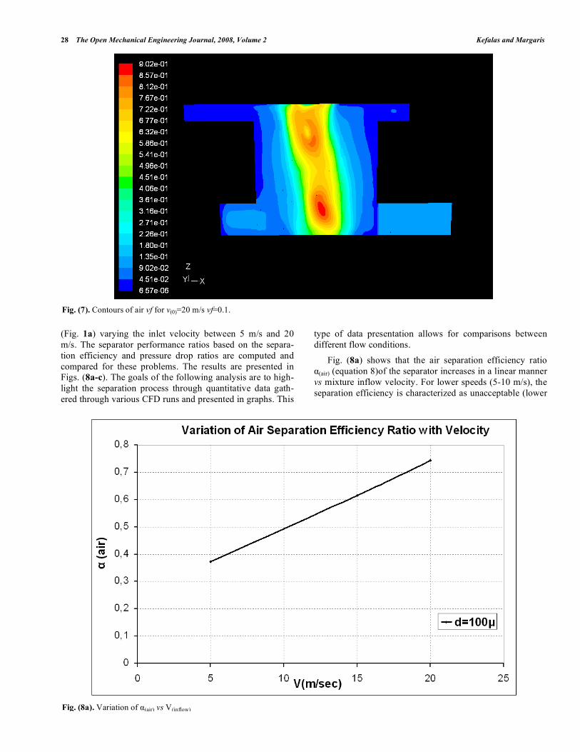
(Fig. 1a) varying the inlet velocity between 5 m/s and 20 m/s. The separator performance ratios based on the separa-tion efficiency and pressure drop ratios are computed and compared for these problems. The results are presented in Figs. (8a-c). The goals of the following analysis are to high-light the separation process through quantitative data gath-ered through various CFD runs and presented in graphs. This
type of data presentation allows for comparisons between different flow conditions.
Fig. (8a) shows that the air separation efficiency ratio α(air) (equation 8)of the separator increases in a linear manner vs mixture inflow velocity. For lower speeds (5-10 m/s), the separation efficiency is characterized as unacceptable (lower
Fig. (7). Contours of air vf for v(0)=20 m/s vf=0.1.
Fig. (8a). Variation of α(air) vs V(inflow)

Numerical Analysis of Fluid Flow in a Compact Phase Separator The Open Mechanical Engineering Journal, 2008, Volume 2 29
than 50%). For speeds in the region of 20 m/s (high speeds) the separation is good (above 70%).
Fig. (8b) shows that the water separation efficiency ratio α(water) (equation 9) is consistently increasing with the flow rate processed by the separator. This efficiency seems to reach an upper limit (stabilizes) at 0.85%.
Fig. (8c) shows that the pressure drop ratio α(p) (equation 10) increases slightly with the flow rates. It remains for all cases tested in the region of 30% pressure drop.
At this point, the general performance of the separator is very close to that of a centrifugal separator [3], operating at the same (or close) conditions, concerning air and liquid separation efficiency.
Fig. (8b). Variation of α(water) vs V(inflow) .
Fig. (8c). Variation of α(p) vs V(inflow).

30 The Open Mechanical Engineering Journal, 2008, Volume 2 Kefalas and Margaris
It is obvious that due to the limited CFD data available at this point no more analysis can be performed on the above presented data because the extracted comments and im-provement recommendations will not be “confident enough”. The above presented data give us a first insight of the behav-ior of the separator under various flow conditions. These data will have to be confirmed by experiments. Once this is achieved it is only a matter of “computational” time to pro-duce graphs with more data and extract more detailed con-clusions.
Experimental Test Results on the Centrifugal Separa-tor: A phase separator with the dimensions given in Fig. (1a) has been constructed from Plexiglas and is presented in Fig. (1b). The experimental tests are the next step of the re-search program. The first tests have already been conducted with very good results. The experimental results will be pre-sented and analysed in future report.
CONCLUSIONS
An investigation of air-water separation process has been conducted using numerical simulation. Separator perform-ance has been analyzed in terms of separation efficiency and pressure drop along the water flow path. The goal of the pre-sent study was to evaluate the predictions of CFD methods for different operating conditions for a fixed geometry of the device. The Multiphase model used for this study is the Mix-ture Model – featured in the commercial code FLUENT6. Steady state analysis was performed for the reported calcula-tions. All the geometrical models, meshes, and numerical models are built and run using parametric journal files. Nu-merical simulation results at different operating conditions, (CFD results) predict correctly that the separator efficiency will increase with the flow rate as well as the pressure drop. Analysis of contours of air volume fraction and flow field patterns showed that the geometry of the separator and spe-cifically the two outlets and the “connecting cylinder”, are to be considered also in improving the performance of the sepa-rator.
NOMENCLATURE
C = Constant or coefficient (-)
D = Characteristic length scale (m)
d = Diameter (m)
f = Function
fdrag = Drag function
g = Acceleration due to gravity (9.81 m/s2)
!m = Mass flow rate (Kgr/s)
n = Exponent
P = Pressure (Pa)
Re = Reynolds number (-)
St = Stokes number (-)
t = Time (s)
U = Characteristic velocity scale (m/s)
u∞ = Free stream velocity (m/s)
υ = Velocity (m/s)
V = Volume (m3)
vf = Volume fraction (-)
x = Horizontal distance (m)
yp = Distance: wall from the adjacent cell centre
z = Vertical distance (m)
Greek Letters
!air
= Air separation efficiency ratio
!water
= Water separation efficiency ratio
aP
= Pressure drop ratio
!! = Acceleration (m/s2)
µ = Viscosity (Pa-s)
ν = Kinematic viscosity (m2/s)
ρ = Density (Kg/m3)
τ = Relaxation time (s)
Subscripts
dr = Drift
in = Inlet - inflow
m = Mixture
max = Maximum
min = Minimum
p = Particulate
q = Primary phase
T = Total
w = Water phase
REFERENCES [1] A.G. Ghiaus, and P.D. Margaris, “Numerical Investigation of a
Novel Compact Separator”, 4th GRACM Cs on Computational Me-chanics, GRACM 2002, 27-29 June, Patras, Greece, 2002.
[2] C. Oropeza-Vazquez, E. Afanador, L. Gomez, S. Wang, R. Mohan, O. Shoham, and G. Kouba, “Oil – water Separation in a Novel Liq-uid – Liquid Cylindrical Cyclone (LLCC©) Compact Separator – Experiments and Modelling” J. Fluids Eng., vol. 126, pp.553-64, 2004.

Numerical Analysis of Fluid Flow in a Compact Phase Separator The Open Mechanical Engineering Journal, 2008, Volume 2 31 [3] T. Barbat, K. Bhatia, and S. Pitla, “CFD Study of Phase Separators
in A/C Automotive Systems” SAE Technical Paper Series, 2003-01-0736, 2003.
[4] FLUENT V6 – Fluent User’s Guide, Fluent, Inc; (2001). [5] M. Manninen, T. Veikko, and K. Sirpa, On the mixture model for
multiphase flow, VTT Publications, Technical Research Centre of Finland, 1996.
[6] M.B. Abbott, and D.R. Basco, Computational Fluid Dynamics-An Introduction for Engineers, Longman, 1989.
[7] S.V. Patankar, and D.B. Spalding, “A calculation procedure for heat, mass and momentum transfer in three dimensional parabolic flows”, Int J Heat Mass Transfer, 15 1787, 1972.
[8] S.V. Patankar, Numerical Heat Transfer and Fluid Flow, McGraw Hill, 1980.
[9] G. Hetsroni, Handbook of Multiphase Systems, Hemisphere, 1982. [10] H. Schlichting, Boundary Layer Theory, McGraw Hill, New York,
1979. [11] J.O. Hintze, Turbulence, McGraw-Hill, New York, 1975.
Received: January 24, 2008 Revised: March 6, 2008 Accepted: April 16, 2008 © Kefalas and Margaris; Licensee Bentham Open.
This is an open access article distributed under the terms of the Creative Commons Attribution License (http://creativecommons.org/licenses/by/2.5/), which permits unrestrictive use, distribution, and reproduction in any medium, provided the original work is properly cited.