numerical analisys of impact … analisys of impact phenomenon between a frangible projectile and...
TRANSCRIPT

Review of the Air Force Academy No.3 (35)/2017
95
NUMERICAL ANALISYS OF IMPACT PHENOMENON BETWEEN
A FRANGIBLE PROJECTILE AND THIN METALLIC PLATES
USED IN AIRCRAFT STRUCTURES
Marius Valeriu CÎRMACI-MATEI
*, Adrian ROTARIU
*, Alexandru DENA
*,
Octavian ORBAN*, Constantin ROTARU**
*Military Technical Academy, Bucharest, Romania ([email protected],
[email protected], [email protected], [email protected]) **
”Henri Coandă” Air Force Academy, Braşov, Romania ([email protected])
DOI: 10.19062/1842-9238.2017.15.3.11
Abstract: This paper shows simulation results whose purpose is to study the impact
occurrence between an anti-hijack pistol projectile and a thin metallic plate. The plate is made of
aluminium alloy used in aeronautical structures. Laboratory tests permitted to analyse the
mechanical behavior of the projectile’s material. The shootings experiments have confirmed the expected impact behavior at given velocity. The model and simulation works were developped
under AUTODYN/ANSYS. The simulation results are well proven by the experimental outcomes.
Keywords: terminal ballistics, FEM, frangible bullet, antihijack projectile, experiment
1. INTRODUCTION
The projectile – target impact phenomenon is complex and is summed up in the study
of involved materials submitted at a specific deformation ratio. The impact conditions
may vary within a wide range and are a function of impact velocity, incident angle,
projectile and target type [1]. The continuous developping trend in ammunition design
and the needs for specialized ammunition bring in front new projectiles, made of new
materials, with complex impact behavior. For these reasons we are dealing with a variety
of terminal ballistics cases. Last period we faced a move from classical ammo to frangible
ammunition, especially for training purposes, in order to reduce the risk. So that not only
the ricochets are avoided but the toxicity of projectiles made of copper powder is less
significant than the lead core bullets show [9].
This is the context of issuing on the market the anti-hijack ammo. The bullets are
made on the basis of copper powder and polymeric binder. The mixture allows a dual
behavior, with respect to target’s nature: the impact with thin metallic plates produces a
bullet smash, in a very short time and without target damage, while a penetration in soft
targets (e.g. ballistic gelatin) occurs. In this paper we are focused on impact analysis
between this kind of projectile and aircraft structure (aluminium thin deformable plates).
Some experimental and laboratory data were used for buiding the simulation cases and
for validating the results.

Numerical Analisys of Impact Phenomenon Between a Frangible Projectile and Thin
Metallic Plates Used in Aircraft Structures
96
2. LABORATOY TESTS
The material used for anti-hijack bullets is a composite of copper powder in a
polymeric matrix and has the property of being frangible due to a mixture of phases with
weak adhesion properties [10]. For this reason, besides compression tests (for Young’s
modulus and yield stress determination) additional tensile tests were made (based on
Brazilian disk test).
FIG. 1 Mechanical behavior of composite copper-polymer material
The experimental results show an elasto-plastic behavior. There are instantaneous
deformations remaining after loading removal. Under the elasticity limit, only elastic
deformations occur. A special case is the elasto-plastic model with a perfect plastic
behavior. If the elasticity limit is reached, the material tension remains at elasticity limit
level. This model can be well represented by a serial connection of a spring and a friction
sleeve (Saint-Venant model).
FIG. 2 Loading scheme of an elastic-perfectly plastic material and Saint-Venant model
Based on experimental results, the mechanical properties according to Saint-Venant
model were defined, as in Table 1.
Review of the Air Force Academy No.3 (35)/2017
97
These data and the Saint-Venant model were used in the part dedicated to numerical
calculus and impact simulations between anti-hijack projectiles and the metallic plates
[11].
Table 1 Mechanical properties of tested material
Properties Projectile material
Young modulus [GPa] 2,11 Yield stress [MPa] 26,58
Poisson coefficient 0,3
Tensile strenght [MPa] 6,20 Density [g/cm
3] 4,8
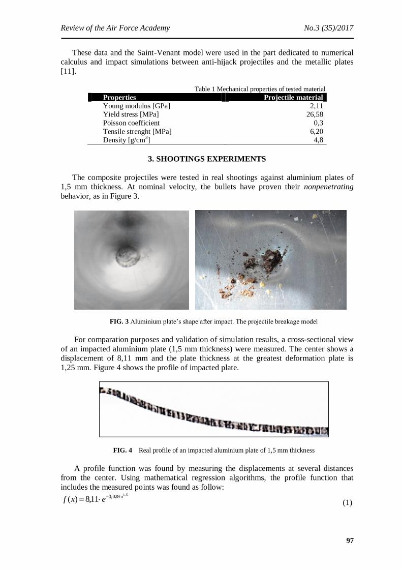
3. SHOOTINGS EXPERIMENTS
The composite projectiles were tested in real shootings against aluminium plates of
1,5 mm thickness. At nominal velocity, the bullets have proven their nonpenetrating
behavior, as in Figure 3.
FIG. 3 Aluminium plate’s shape after impact. The projectile breakage model
For comparation purposes and validation of simulation results, a cross-sectional view
of an impacted aluminium plate (1,5 mm thickness) were measured. The center shows a
displacement of 8,11 mm and the plate thickness at the greatest deformation plate is
1,25 mm. Figure 4 shows the profile of impacted plate.
FIG. 4 Real profile of an impacted aluminium plate of 1,5 mm thickness
A profile function was found by measuring the displacements at several distances
from the center. Using mathematical regression algorithms, the profile function that
includes the measured points was found as follow: 5,1028,011,8)( xexf (1)

Numerical Analisys of Impact Phenomenon Between a Frangible Projectile and Thin
Metallic Plates Used in Aircraft Structures
98
FIG. 5 The impacted profile’s approximation function and measured points on the profile.
The maximum value of the function is 8,11 mm – the impact center displacemet
4. NUMERICAL MODEL
The model was built under Autodyn, considering a 3D nonlinear formulation. All
involved materials have nonlinear behavior.
The code allows the use of the three solvers: Lagrange, Euler and SPH. Due to
specific behavior of the materials and the characteristics of impact phenomenon, we
decided to use the Lagrange solver for the impacted structure. For the projectile
deformation, we have used both Lagrange and SPH solvers. The numerical studies
considered the similar case as in real shootings, i.e. anti-hijack projectile impact with
aluminium plates of 1,5 mm thickness. Table 2 comprises the model configuration.
Tabelul 2 Model configuration
Configuration Type Material Solver Innitial conditions
1
Projectile Anti-hijack Copper powder in polymeric matrix
Lagrange V0 = 330 m/s
Target Al plate
1,5 mm Al 2024 T3 Lagrange
Shell;
V0 = 0 m/s
2
Projectile Anti-hijack Copper powder in polymeric matrix
SPH V0 = 330 m/s
Target Al plate
1,5 mm Al 2024 T3 Lagrange
Shell;
V0 = 0 m/s
For the projectile we have used an elastic – perfectly plastic material model. The
characteristics are given in Table 3. For the aircraft structure material we have used a
material model which allows shell elements discretization (uniform stress and strain in
plate’s depth) for reducing the solving time. The chosen model was completed with the
characteristics of aluminium 2024, T3, according to French standard 9048 AIR -
Conditions de controle des produits lamines en alliages d’aluminium utilises dans les
constructions aerospatiales).
Tabel 3 Johnson-Cook constitutive constants for aluminium 2024-T3
Material Density
(kg/m3)
Specific heat
(J/kgK)
Melting
temperature (K)
A
(MPa)
B
(MPa)
N C M
Aluminium
2024-T3
2770 875 775 265 426 0,34 0,015 1,00
The decission of using SPH solver for the projectile arised as a necessity in this kind of
impact. The deformation and, eventually, penetration of the plate are dependent on the amount of transferred momentum and energy, as well as being dependent on the way in this transfer occurs.
Review of the Air Force Academy No.3 (35)/2017
99
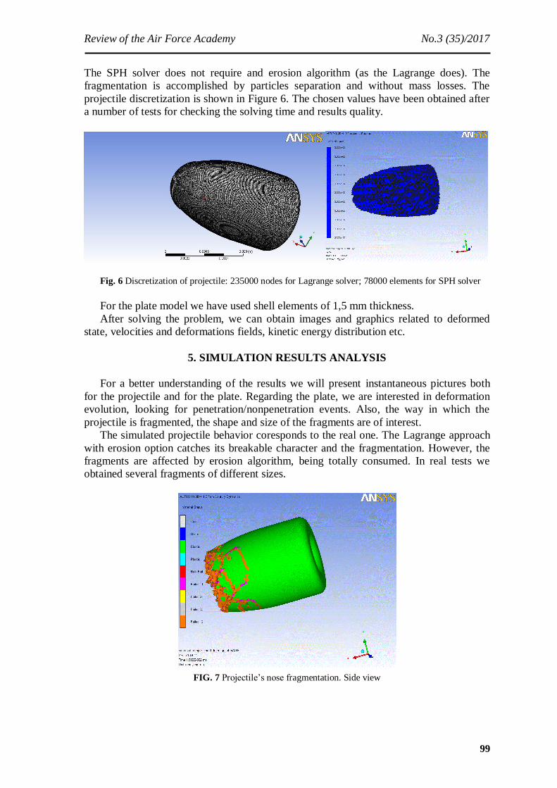
The SPH solver does not require and erosion algorithm (as the Lagrange does). The
fragmentation is accomplished by particles separation and without mass losses. The
projectile discretization is shown in Figure 6. The chosen values have been obtained after
a number of tests for checking the solving time and results quality.
Fig. 6 Discretization of projectile: 235000 nodes for Lagrange solver; 78000 elements for SPH solver
For the plate model we have used shell elements of 1,5 mm thickness.
After solving the problem, we can obtain images and graphics related to deformed
state, velocities and deformations fields, kinetic energy distribution etc.
5. SIMULATION RESULTS ANALYSIS
For a better understanding of the results we will present instantaneous pictures both
for the projectile and for the plate. Regarding the plate, we are interested in deformation
evolution, looking for penetration/nonpenetration events. Also, the way in which the
projectile is fragmented, the shape and size of the fragments are of interest.
The simulated projectile behavior coresponds to the real one. The Lagrange approach
with erosion option catches its breakable character and the fragmentation. However, the
fragments are affected by erosion algorithm, being totally consumed. In real tests we
obtained several fragments of different sizes.
FIG. 7 Projectile’s nose fragmentation. Side view

Numerical Analisys of Impact Phenomenon Between a Frangible Projectile and Thin
Metallic Plates Used in Aircraft Structures
100
The impact phenomenon lasts 0,1 ms. Thus, at 0,15 ms the bullet is eliminated from
the simulation. A critical analysis of the energy transfer between the bullet and the plate is
needful.
FIG. 8 Energy transfer at impact in Lagrange approach
First, we observe that the total energy of the bullet is similar with its kinetic energy
evolution, so that the bullet material doesn’t faces a deformation work or an elastic
energy. This is because of the rapid erosion of the nodes. This is a condition imposed by
the breakable nature of the material. Also, we meet an elimination from the model of the
associated energy, excepting the kinetic energy of the nodes. So that, even if the model is
functional, it doesn’t respect the principle of energy conservation. In Figure 9 the free
nodes evolution at a given moment can be observed as having inertia. As they are
released from the network, some of them go beyond the aluminium plate and quickly
disperses. However, this unrealistic event comes with a momentum transfer to the plate.
As we already noted, the energy transfer is finished at 0,1 ms, even the simulation shows
that the projectile is fully consumed by erosion at 0,64 ms. As a conclusion, the Lagrange
approach leads to an incomplete energy transfer from the free nodes to the plate and even
unrealistic, as the plate does not break, nor crack.
FIG. 9 Free nodes behavior within impact phenomenon. Lagrange approach
The results shows a maximum displacement of 9,47 mm in the impact center, at
0,176 ms.
Review of the Air Force Academy No.3 (35)/2017
101
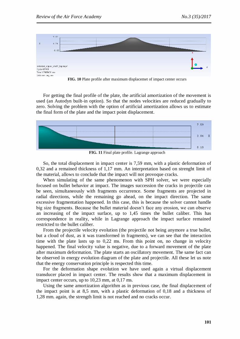
FIG. 10 Plate profile after maximum displacemet of impact center occurs
For getting the final profile of the plate, the artificial amortization of the movement is
used (an Autodyn built-in option). So that the nodes velocities are reduced gradually to
zero. Solving the problem with the option of artificial amortization allows us to estimate
the final form of the plate and the impact point displacement.
FIG. 11 Final plate profile. Lagrange approach
So, the total displacement in impact center is 7,59 mm, with a plastic deformation of
0,32 and a remained thickness of 1,17 mm. An interpretation based on strenght limit of
the material, allows to conclude that the impact will not provoque cracks.
When simulating of the same phenomenon with SPH solver, we were especially
focused on bullet behavior at impact. The images succession the cracks in projectile can
be seen, simultaneously with fragments occurrence. Some fragments are projected in
radial directions, while the remaining go ahead, on the impact direction. The same
excessive fragmentation happened. In this case, this is because the solver cannot handle
big size fragments. Because the bullet material doesn’t face any erosion, we can observe
an increasing of the impact surface, up to 1,45 times the bullet caliber. This has
correspondence in reality, while in Lagrange approach the impact surface remained
restricted to the bullet caliber.
From the projectile velocity evolution (the projectile not being anymore a true bullet,
but a cloud of dust, as it was transformed in fragments), we can see that the interaction
time with the plate lasts up to 0,22 ms. From this point on, no change in velocity
happened. The final velocity value is negative, due to a forward movement of the plate
after maximum deformation. The plate starts an oscillatory movement. The same fact can
be observed in energy evolution diagram of the plate and projectile. All these let us note
that the energy conservation principle is respected this time.
For the deformation shape evolution we have used again a virtual displacement
transducer placed in impact center. The results show that a maximum displacement in
impact center occurs, up to 10,23 mm, at 0,17 ms.
Using the same amortization algorithm as in previous case, the final displacement of
the impact point is at 8,5 mm, with a plastic deformation of 0,18 and a thickness of
1,28 mm. again, the strength limit is not reached and no cracks occur.

Numerical Analisys of Impact Phenomenon Between a Frangible Projectile and Thin
Metallic Plates Used in Aircraft Structures
102
FIG. 12 Projectile fragmentation at impact. Gradual instants
FIG. 13 Plate’s profile at maximum displacement of the impact center
Review of the Air Force Academy No.3 (35)/2017
103
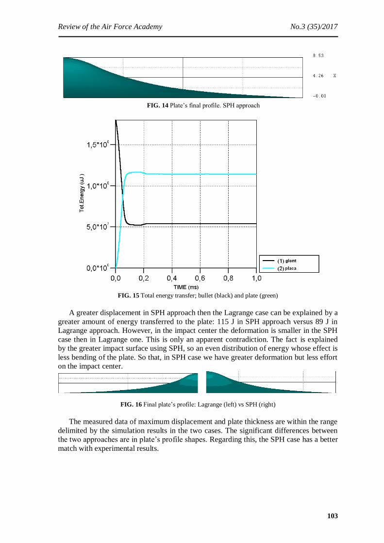
FIG. 14 Plate’s final profile. SPH approach
FIG. 15 Total energy transfer; bullet (black) and plate (green)
A greater displacement in SPH approach then the Lagrange case can be explained by a
greater amount of energy transferred to the plate: 115 J in SPH approach versus 89 J in
Lagrange approach. However, in the impact center the deformation is smaller in the SPH
case then in Lagrange one. This is only an apparent contradiction. The fact is explained
by the greater impact surface using SPH, so an even distribution of energy whose effect is
less bending of the plate. So that, in SPH case we have greater deformation but less effort
on the impact center.
FIG. 16 Final plate’s profile: Lagrange (left) vs SPH (right)
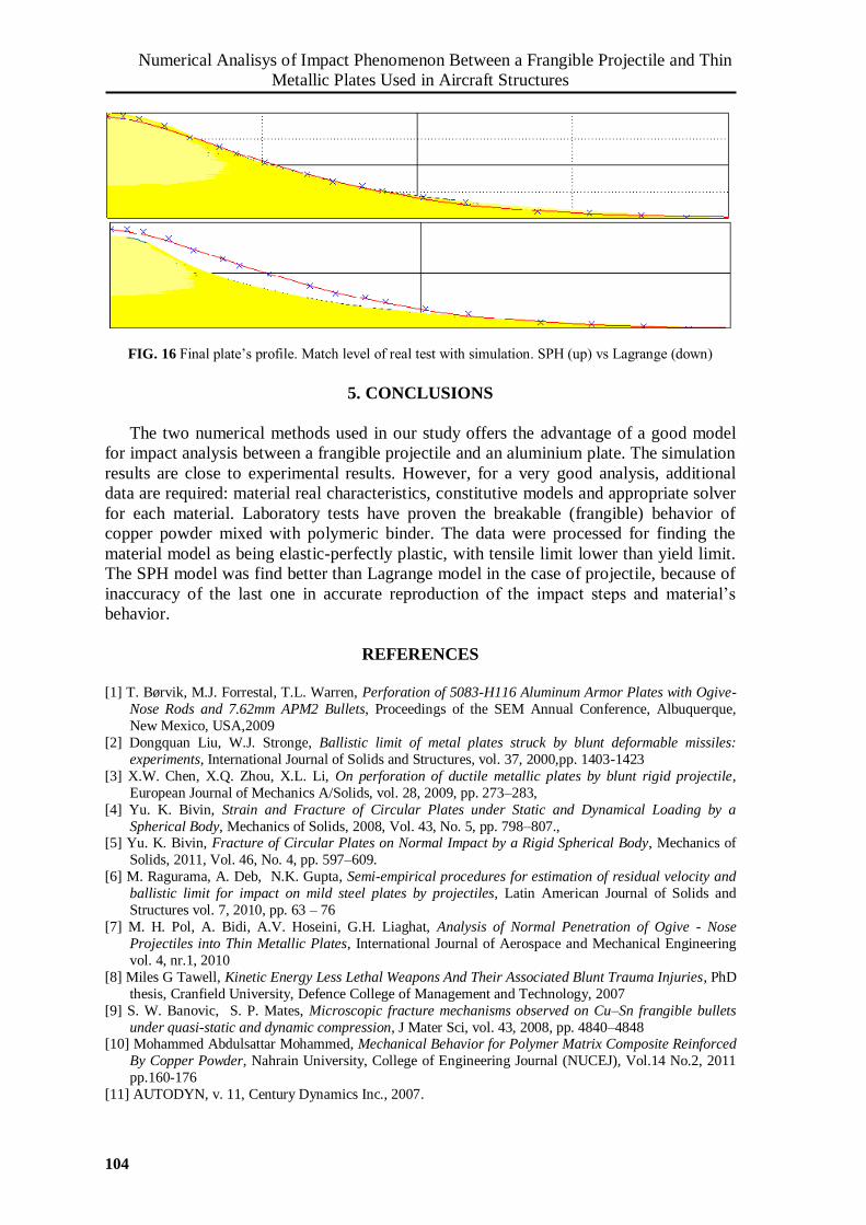
The measured data of maximum displacement and plate thickness are within the range
delimited by the simulation results in the two cases. The significant differences between
the two approaches are in plate’s profile shapes. Regarding this, the SPH case has a better
match with experimental results.
Numerical Analisys of Impact Phenomenon Between a Frangible Projectile and Thin
Metallic Plates Used in Aircraft Structures
104
FIG. 16 Final plate’s profile. Match level of real test with simulation. SPH (up) vs Lagrange (down)
5. CONCLUSIONS
The two numerical methods used in our study offers the advantage of a good model
for impact analysis between a frangible projectile and an aluminium plate. The simulation
results are close to experimental results. However, for a very good analysis, additional
data are required: material real characteristics, constitutive models and appropriate solver
for each material. Laboratory tests have proven the breakable (frangible) behavior of
copper powder mixed with polymeric binder. The data were processed for finding the
material model as being elastic-perfectly plastic, with tensile limit lower than yield limit.
The SPH model was find better than Lagrange model in the case of projectile, because of
inaccuracy of the last one in accurate reproduction of the impact steps and material’s
behavior.
REFERENCES
[1] T. Børvik, M.J. Forrestal, T.L. Warren, Perforation of 5083-H116 Aluminum Armor Plates with Ogive-
Nose Rods and 7.62mm APM2 Bullets, Proceedings of the SEM Annual Conference, Albuquerque,
New Mexico, USA,2009
[2] Dongquan Liu, W.J. Stronge, Ballistic limit of metal plates struck by blunt deformable missiles:
experiments, International Journal of Solids and Structures, vol. 37, 2000,pp. 1403-1423
[3] X.W. Chen, X.Q. Zhou, X.L. Li, On perforation of ductile metallic plates by blunt rigid projectile,
European Journal of Mechanics A/Solids, vol. 28, 2009, pp. 273–283,
[4] Yu. K. Bivin, Strain and Fracture of Circular Plates under Static and Dynamical Loading by a
Spherical Body, Mechanics of Solids, 2008, Vol. 43, No. 5, pp. 798–807., [5] Yu. K. Bivin, Fracture of Circular Plates on Normal Impact by a Rigid Spherical Body, Mechanics of
Solids, 2011, Vol. 46, No. 4, pp. 597–609.
[6] M. Ragurama, A. Deb, N.K. Gupta, Semi-empirical procedures for estimation of residual velocity and
ballistic limit for impact on mild steel plates by projectiles, Latin American Journal of Solids and
Structures vol. 7, 2010, pp. 63 – 76
[7] M. H. Pol, A. Bidi, A.V. Hoseini, G.H. Liaghat, Analysis of Normal Penetration of Ogive - Nose
Projectiles into Thin Metallic Plates, International Journal of Aerospace and Mechanical Engineering
vol. 4, nr.1, 2010
[8] Miles G Tawell, Kinetic Energy Less Lethal Weapons And Their Associated Blunt Trauma Injuries, PhD
thesis, Cranfield University, Defence College of Management and Technology, 2007
[9] S. W. Banovic, S. P. Mates, Microscopic fracture mechanisms observed on Cu–Sn frangible bullets
under quasi-static and dynamic compression, J Mater Sci, vol. 43, 2008, pp. 4840–4848 [10] Mohammed Abdulsattar Mohammed, Mechanical Behavior for Polymer Matrix Composite Reinforced
By Copper Powder, Nahrain University, College of Engineering Journal (NUCEJ), Vol.14 No.2, 2011
pp.160-176
[11] AUTODYN, v. 11, Century Dynamics Inc., 2007.