number 1, 2005 scientific drilling - icdp-online.org · the icdp lake bosumtwi drilling project: a...
TRANSCRIPT

Reports on Deep Earth Sampling and Monitoring
NU
MB
ER
1,
20
05
Arctic Cores Show Greenhouse to Icehouse Change 12
Studying the Roots of the Active Unzen Volcano 18
Impact Crater Reveals North African Monsoon History 23
Approaching the Mantle in the Atlantic? 28
Inaugural Issue
Published by the Integrated Ocean Drilling Program with the International Continental Scientific Drilling Program
Eastern Pacific Borehole Observatories Installed to Monitor Fluid Flow 6
Scientific Drilling

Scientific DrillingISSN: 1816-3459 (electronic version)
Scientific Drilling is a semiannual journal published jointly by the Integrated Ocean Drilling Program Management International (IODP-MI) with the International Continental Scienti f ic Dril l ing Program (ICDP). It is designed to enhance communication between and among IODP and ICDP, and other scien-tific drilling communities. IODP and ICDP welcome contributions on any aspect of scien-tific drilling, including borehole instruments, observatories, and monitoring experiments. The journal is produced and distributed by IODP-MI for the Integrated Ocean Drilling Program ( IODP) under the sponsorship of the U.S. National Science Foundation, the Ministry of Culture, Education, Sports, Science and Technology of Japan, and other participating countries. The journal’s content is partly based upon research supported under Cont ract OCE - 0 432224 f rom the National Science Foundation.
Electronic versions, as well as information for authors, can be found at http://www.iodp.org/scient i f ic -dr i l l ing/ and ht tp://www.icdp-online.de/scientif ic-drilling/. Printed versions of this publication can be requested from the publication office.
IODP is an international marine research dril l ing program dedicated to advancing scient i f ic understanding of the Earth by mon i t or i ng a nd s a mpl i ng subs ea f loor environments. Through multiple platforms, IODP scientists explore the program’s principal themes: the deep biosphere, environmental change, and solid earth cycles.
ICDP is a multi-national program designed to promote a nd coord inate cont inent a l drilling projects with a variety of scientific targets at drilling sites of global significance.
Publication Office: IODP-MI, CRIS Building-Room 05-101, Hokkaido University, N21W10 Kita-ku, Sapporo, 001-0021 Hokkaido, Japan. Tel: +81-11-738 1075, Fax: +81-11-738 3520. e-mail: [email protected],www: www.iodp.org/scientific-drilling/
Editorial Board:Editor-in-Chief: Hans Christian Larsen Managing Editor: Emanuel SoedingEditors: Ulrich Harms, Jeffrey D. Schuffert
Send comments to: [email protected]
Layout & Design: Advanced Earth Science and Technology Organization (AESTO), Japan and Mhley/Davis and Associates, Washington, DC, U.S.A.
Production and Printing: Saneatsu Saito andSOHOKKAI, Co. Ltd.
IODP-MI Washington, DC, U.S.A.Sapporo, Japanwww.iodp.org
ICDPGeoForschungsZentrum PotsdamPotsdam, Germanywww.icdp-online.de
All figures and photographs courtesy of the IODP, unless otherwise specified.
Cover: The Japanese dril l ing vessel Chikyu sets sail for a short testing cruise in spring 2005. The Chikyu was delivered by Mitsubishi Heavy Industries Ltd. (MHI) to the Japan Agency for Marine-Earth Science and Technology (JAMSTEC) in Nagasaki on 29 July 2005. The contribution of the Chikyu to the Integrated Ocean Drilling Pro-gram represents a milestone in scientific drilling (see article on p. 32). Cover inset photo: The Unzen Scientific Drill-ing Project sampled the magma conduit from the 1991-1995 eruptions of the Unzen Volcano, Japan (see report on p. 18, photo credit: ICDP).Left: The delivery ceremony of the Chikyu to JAMSTEC. Pictured are Kazunori Ohta (left), Managing Director and General Manager of Shipbuilding & Ocean Development Headquarters of MHI, Asahiko Taira (center), Director General of the Center for Deep Earth Exploration (CDEX), and Yasuhiro Kato (right), President of JAMSTEC.
� Scientific Drilling, Number 1, 2005
Dear Reader:
Welcome to a new era of scientific drilling on land and at sea! This new journal, Scientific Drilling, represents a collaborative effort between the Integrated Ocean Drilling Program and the International Continental Scientific Drilling Program. These two programs pursue many common and intriguing scientific themes around the globe, such as climate and environmental change, extraterrestrial impacts, the deep biosphere, the mechanisms of devastating earthquakes, the dynamics of plate tectonics, the flow of fluids and magma in the crust, and the formation of large igneous provinces.
We recognize the growing importance and interest in scientific drilling regardless of where, when, or how it occurs, and we aim to promote a strong, cohesive feeling of joint enterprise among an expanding community of participants. We also aim to highlight the crucial role that scientific drilling plays in understanding the workings of our planet and the environmental challenges faced by modern society. We therefore welcome contributions on any aspect of scientific drilling, including borehole instruments, observatories, and monitoring experiments. This journal provides a forum for brief scientific reports, technology-based contributions of wide interest, synthesis papers, and news about workshops, work planned, or work in progress.
The variety of reports published in this first issue reflects well on our mission of serving a broad community. In any event we hope you enjoy the journal and will consider joining us in promoting the full spectrum of scientific endeavors involved in deep Earth sampling and monitoring.
Editorial Preface
Emanuel SoedingManaging Editor
Hans Christian LarsenEditor-in-Chief
Jeff SchuffertEditor
Ulrich HarmsEditor

Scientific Drilling, Number 1, 2005 �
IODP Expedition 301 Installs Three Borehole Crustal Observatories, Prepares for Three-Dimensional, Cross-Hole Experiments in the Northeastern Pacific Ocean
Andrew T. Fisher, Tetsuro Urabe, Adam Klaus, and the IODP Expedition 301 Scientists
IODP Expedition 302, Arctic Coring Expedition (ACEX): A First Look at the Cenozoic Paleoceanography of the Central Arctic Ocean
Jan Backman, Kathryn Moran, David McInroy, and the IODP Expedition 302 Scientists
12
6
Scientific Results of Conduit Drilling in the Unzen Scientific Drilling Project (USDP)
Setsuya Nakada, Kozo Uto, Sumio Sakuma, John C. Eichelberger and Hiroshi Shimizu
18
The ICDP Lake Bosumtwi Drilling Project: A First ReportChristian Koeberl, John Peck, John King, Bernd Milkereit, Jonathan Overpeck, and Christopher Scholz
23
Joining Forces in Scientific Drilling4Science Reports
Foreword
28 IODP Expeditions 304 and 305: Oceanic Core Complex Formation, Atlantis Massif
Progress Reports
32 The Chikyu: Meeting the Challenges of a New Scientific Drilling Era
34 New Opportunities in Riserless Ocean Drilling
36 From the North Pole to Tahiti— Initial Experiences with IODP and MSPs
Program Developments
40 The Inaugural SHALDRIL Expedition to the Weddell Sea, Antarctica
Reports from Related Programs
44 Drilling the Eger Rift in Central Europe
46 Paleoceanography and Paleoclimatology of the Southern Ocean: A Synthesis of Three Decades of Scientific Ocean Drilling
Workshop Reports
47 News
50 IODP's Untapped Wealth: Multiparameter Logging of Legacy Core
News and Views
back IODP and ICDP Expedition and Project Schedules
Schedules

� Scientific Drilling, Number 1, 2005
E stablished in October 2003, the Integrated Ocean Drilling Program (IODP) comprises an interna-
tional marine research endeavor to explore the history, structure, dynamics, and special habitats of the Earth system through the study of sediments, rocks, fluids, and organisms from beneath the seafloor. The IODP aspires to expand the success of its predecessors, the Deep Sea Drilling Project (DSDP) and the Ocean Drilling Program (ODP), and advance across new frontiers of scientif ic research into previously inaccessible environments.
Our ten-year init ial science plan, “Earth, Oceans and Life”, describes in detail several specific initiatives concerning the deep biosphere, gas hydrates, climate extremes, rapid climate change, continental rifting, large igneous provinces, seismogenic zones, and the Moho. To accomplish such an ambitious plan, we will employ multiple drilling platforms, develop new sampling, logging, and monitoring technologies, and embrace a more diverse scientif ic community. Our technical capabilit ies will soon increase dramatically with the first expeditions on the Chikyu, an impressive new riser-equipped drilling vessel provided by Japan. Together with riserless drilling conducted for now on the U.S.-provided JOIDES Resolution and mission-specific platforms provided by Europe, the IODP expects to operate safely and effectively in almost any geographical setting of the world ocean.
These enhanced capabilities present a great opportunity for building new partnerships and formulating new ideas, but we also face the daunting challenge of ensuring that such a complex program works in a truly integrated way in terms of its management, resources, and products. Toward those ends, we have already taken pioneering steps to broaden and strengthen our collaborative network of scientists and other experts. For example, we have created special task forces to review the immediate outcome of our expeditions, established a management forum for national and international IODP leaders, and begun efforts to foster a new relationship with industry. We also hope that the recent launch of our new Web site (www.iodp.org) serves the purpose of knitting together the various strands of our community into a seamless whole.
Beyond those ef forts, this new journal, Scientif ic Drilling, represents an excit ing and visible example of an important partnership in the making. Since the IODP and the Internat ional Cont inenta l Scient i f ic
D r i l l i n g P rog r a m ( ICDP ) a l re ady pu r sue m a ny com mon goa ls a nd s t r a t eg ies , i t seems ent i re ly natural that we should share a journal as well. Our two programs have much to gain from each other and much to learn about scientif ic drill ing, no matter where it occurs, and we look forward to publ ishing a broad range of articles that will serve as a valuable resource to members of both communities.
I wish also to acknowledge the support of the U.S. National Science Foundation and Japan's Ministry of Education, Culture, Sports, Science, and Technology. Their commitment to the Integrated Ocean Drill ing Program enables us not only to launch this journal, but to expand our outreach in general, to the greater scientific community and the public at large.
Manik TalwaniPresident & CEOIntegrated Ocean Drilling ProgramManagement International
Foreword
Joining Forces in Scientific Drilling

Scientific Drilling, Number 1, 2005 �
F ollowing a decade of success and growing global partici-pation, the International Continental Scientific Drilling
Program (ICDP) is realigning itself toward eight strategic research topics and priority locations where drilling is the only instrument that can provide reliable answers to key questions in Earth science. The themes that the ICDP will address in the forthcoming years were identified during a major program planning conference in March 2005 and include climate change and global environment, impact structures, geobiosphere and early life, volcanic systems and thermal regimes, mantle plumes and rifting, active faulting, collision zones and convergent margins, and natural resources. Each project within the ICDP framework is techni-cally accomplished with drilling platforms, services of oppor-tunity, and complementary ICDP-owned equipment where needed to accomplish the science goals.
The coincidence of restructuring and new orientation offers a unique opportunity to consider strategic alliances between the IODP and the ICDP. It is time to establish strong ties in addition to existing programmatic links. In both partner programs, there is a major overlap in the scientific goals that lead and drive each drilling project and all samples retrieved and studied. From extrater-restrial sources of climatic changes to magma extraction processes in the deepest mantle and buried life forms, we strive to obtain a better understanding of processes shaping and changing the Earth.
Given the large homogeneity in research targets, we should consider defining preferential focus themes that could be jointly addressed during a specific time interval. For instance, amphibious projects with parallel or successive land-based and marine operations would provide an excellent focus for such coordinated complex research. Specific target areas include subduction zones with complex fault ing processes. Perhaps, the most tangible manifestation on a centennial scale of plate tectonics, the Sumatra event in December 2004, springs to mind as a possible long-term target. Our programs will have to establish a mechanism to endorse coordinated actions such as the proposed amphibian projects.
Furthermore, we share the same needs for instru-mentation and technical developments in the f ield of long-term monitoring and downhole logging, especially for stress and strain measurements in boreholes within hostile environments. The instrumentation on either side needs to be concerted and coordinated. Existing task forces and operational support services simply need synchronizing with regard to commonly targeted scien-tific focus tasks.
A further step toward establishing a close partnership between IODP and ICDP is the joint publication of this new journal, Scientific Drilling. The goal is to provide a communication vehicle for plans and progress in all drilling research projects, including deep earth sampling and monitoring on land, on sea, on ice, in caves, or in mines, advanced and funded through initiatives at national and international levels.
Rolf EmmermannChairman of the Executive CommitteeInternational Continental Scientif ic Drilling Program
Foreword

� Scientific Drilling, Number 1, 2005
Introduction and GoalsThe basaltic upper oceanic crust comprises the largest
aquifer on Earth, containing a volume of water about equal to that currently stored in ice sheets and glaciers. Annual f luid f luxes through the upper oceanic crust are at least as large as the global river flux to the ocean. Much of the seaf loor is hydrogeologically active, but the majority of the fluid flow within oceanic crust occurs on ridge flanks, regions located kilometers or more from active seaf loor spreading centers. Fluid circulation in these areas is driven mainly by lithospheric heat rising from deep within the plate but is influenced by seafloor and basement topography, seismic and tectonic events, and tides.
Subseaf loor f luid f low on ridge f lanks inf luences a diverse array of processes and properties, including the thermal state and evolution of oceanic plates, alteration of the lithosphere and crustal pore waters, establishment and maintenance of vast subseaf loor microbial ecosystems, and diagenetic, seismic, and magmatic activity along plate-boundary faults. Although numerous drilling expeditions and surface and submersible surveys over the last several decades have focused on hydrogeologic phenomena, we still know relatively little about driving forces, property distribu-tions, scales of flow, rates of flow, extent of compartmental-ization or isolation of distinct f luid-rock systems, or links between hydrogeologic, geochemical, microbiological, and geophysical processes. Progress through drilling has been limited in the past by the perturbing effects of borehole creation on subseafloor thermal, pressure, chemical, and biological conditions. Subseafloor observatories address this challenge by allowing the formation to recover from drilling perturbations, and also allow scientists to run passive and active experiments for years to decades.
IODP Expedition 301 was part of a multi-disciplinary program designed to evaluate the formation-scale hydrogeo-logic properties within oceanic crust, determine how fluid pathways are distributed within an active hydrothermal system, and elucidate relations between fluid circulation, alteration, microbiology, and seismic properties. The complete experimental program will comprise two IODP expeditions (the f irst having been Expedition 301, the second to be scheduled), an offset seismic experiment, and long-term monitoring and cross-hole tests facilitated with submersible and remotely operated vehicle (ROV) expedi-
tions extending 6–10 years after the first IODP expedition. The experimental program will also take advantage of opportunities related to a plate-scale network of long-term observatories (NEPTUNE) currently being planned.
Experimental Setting and Earlier WorkThe Endeavour segment of the Juan de Fuca Ridge (JFR)
generates lithosphere west of North America. Topographic relief produces barriers to turbidites from the continental margin, resulting in the accumulation of sediment over the eastern f lank of the JFR, particularly during Pleistocene sea-level low stands. This resulted in burial of oceanic basement rocks under thick sediments at a young age. Sediment cover is sparse and oceanic basement is exposed near the active ridge at the western end of this ridge flank (Fig. 1). The sediment layer becomes thicker and more continuous to the east, with basement exposed at only a few, isolated outcrops. Basement relief is dominated by linear ridges and troughs oriented subparallel to the spreading center and produced mainly by fault ing, variations in magmatic supply at the ridge, and of f-axis volcanism. Basement relief is low (±100–200 m) near the active ridge and higher (±300–700 m) to the east. Low-permeability sediment limits advective heat loss across most of the ridge flank, resulting in strong thermal, chemical, and alteration gradients in the basement.
An 80-km transect comprising ten sites was drilled on the eastern flank of the JFR during ODP Leg 168 (Davis et al., 1997), including sites aged 0.9–3.6 Ma (Fig. 1). Thermal observations at the western end of the Leg 168 transect showed that basement was cooled by seawater recharging from nearby basement outcrops. Upper basement tempera-tures were remarkably isothermal at the eastern end of the drilling transect, despite extreme basement relief below thick sediments, giving evidence for vigorous convection in the oceanic crust. Upper basement temperatures generally increase from ~15˚C at the western end of the transect to ~64˚C at the eastern end. This overall trend in basement temper-atures might suggest that the dominant direction of f luid f low is from west to east, but sedimentary and basement pore fluid samples are inconsistent with this interpretation. The western end of the transect shows increasing alteration from west to east, but f luid recovered from sites in the middle of the transect was anomalously altered (Elderfield et al., 1999). The chemistry of these fluids is most consistent with that of f luids recovered from eastern Sites 1026 and
Science Reports
IODP Expedition 301 Installs Three Borehole Crustal Observatories, Prepares for Three-Dimensional, Cross-Hole Experiments in the Northeastern Pacific Ocean
by Andrew T. Fisher, Tetsuro Urabe, Adam Klausand the IODP Expedition �01 Scientists
doi:10.��0�/iodp.sd.1.01.�00�

Scientific Drilling, Number 1, 2005 �
1027 and from springs on nearby Baby Bare outcrop (Wheat and Mottl, 2000). Fluid 14C analyses revealed some of the youngest crustal fluids at Site 1026 (Elderfield et al., 1999), but it is not possible for waters recharging the basement aquifer near the western end of the Leg 168 transect to become younger as they travel to the east and become increasingly altered. There is geochemical evidence for along-strike (south-to-north) f luid transport in basement (Wheat et al., 2000), and thermal data and hydrogeologic calculations show that recharge of Baby Bare outcrop springs (and of basement fluid recovered from Site 1026) most likely occurs through a larger basement outcrop ~50 km to the south (Fisher et al., 2003).
Borehole hydrogeologic experiments completed in several Leg 168 basement holes indicated near-borehole formation permeabilities of 10-14 to 10-10 m2, with the highest permeabilities determined for the youngest sites (Becker and Davis, 2003; Becker and Fisher, 2000). These data are broadly consistent with the rest of the global data set and suggest two additional trends: a decrease in uppermost basement permeability with increasing age and variations in permeability estimated using methods with different measurement scales. Circulation Obviation Retrofit Kit (CORK) observatories were installed during Leg 168 at western Sites 1024 and 1025 and eastern Sites 1026 and 1027 to monitor borehole fluid pressure and temperature and to
collect long-term fluid samples within uppermost basement. Borehole f luid responses to tidal loading and regional tectonic events indicate effective basement permeability as great as 10-9 m2, similar to values inferred from numerical and analytical calculations (e.g., Davis and Becker, 2004; Spinelli and Fisher, 2004).
Hole 1026B also yielded direct observations of ridge-flank fluid microbiology. Samples collected during drilling suggested the presence of microbes, and seafloor experi-ments assessed microbial biomass and diversity in f luids venting from the CORK observatory (Cowen et al., 2003). Cells collected from the wellhead included bacteria and archaea, whose closest known phylogenetic neighbors comprise nitrate reducers, thermophilic sulfate reducers, and thermophilic fermentative heterotrophs, consistent with basement fluid geochemistry. These tantalizing results encourage additional study of the basement biosphere.
Drilling, Sampling, Testing, and Installing Borehole Observatories
IODP Site U1301 was positioned 1 km south-southwest of ODP S ite 1026 , above a bur ied basement r idge where sediment thins to 250–265 m (Fig. 1). We cored upper basement in Hole U1301B to ~580 mbsf (~320 m sub-basement, msb), with ~30% recovery, typical for basaltic crust. Samples were collected to study lithostratigraphy,
Science Reports
Figure 1. (A) Index map of field area, eastern flank of the Juan de Fuca Ridge, showing locat ion of ODP Leg 168 transect and IODP Expedition 301 sites. (B) Seafloor bathymetric contour map of area around IODP Expedition 301 sites showing spatial relations between CORK observatories (colored circles) in Holes 1026B, 1027C, U1301A, U1301B, planned Site SR-2, and nearby basement outcrops (gold bathymetric contours ) . Depth contours in meters. (C) Perspective basement map of IODP Expedition 301 drilling area, showing ODP and IODP hole locations (Zühlsdorff et al., in press). Sediment has been digitally removed to show basement relief below largely flat seafloor. The map is based on bathymetry shown in Fig. 1B and interpretation of ~25 seismic lines collected during the ImageFlux expedition with the german research vessel Sonne in 2000. Holes at Site SR-2 will be drilled during the next drilling expedition. Holes 1026B and U1301A/B are ~1 km apart, whereas Holes 1026B and 1027C are 2.2 km apart. Hole SR-2B will be the perturbation wel l for three-dimensional, cross-hole experiments that will last several years.

alteration, microbiology, and paleomagnetic and physical properties. Nearly 9% of recovered basement rocks were dedicated to microbiological analyses. We also collected high-quality advanced piston corer (APC) sediment cores immediately above basement to sample fluid chemistry and microbiology. Wireline logging data from the lower part of Hole U1301B indicate that the hole is to gauge and that the crust is highly layered. Comparison with other crustal holes shows that we achieved a critical basement observatory objective: isolating upper and lower parts of extrusive crust. Packer experiments completed in Holes U1301A and U1301B show that the upper crust is highly permeable, perhaps >10 -10 m2, and bulk permeability may decrease slightly with depth (Fisher et al., in press a).
We replaced the CORK observatory in Hole 1026B;\ , created new basement Holes U1301A and U1301B that penetrate 108 and 320 msb, respectively, and instrumented each of these holes with COR K observatories (Figs. 1 and 2). CORK handling and installation is illustrated in Figure 3. Site U1301 basement holes and observatories are separated by just 35 m. All new CORK observatories have multiple isolated intervals to monitor and sample pressure, temperature, chemistry, and microbiology and will serve as observation points for cross-hole experiments (Fig. 2). Holes 1026B and U1301A each include one monitored zone in uppermost basement, and there are three basement zones being monitored in Hole U1301B. The uppermost basement zones in these holes are in rubbly, brecciated rock, whereas the deepest crustal zone in Hole U1301B appears to be consid-erably more massive and stable, although it is also highly permeable. These CORK observatories include plumbing that allows us to monitor intervals between the two inner casing strings (Fig. 2A) and assess the quality of hydrologic seals. We also planned to replace the CORK system in Hole 1027C during IODP Expedition 301 but ran out of time and supplies. The old CORK system is currently monitoring basement fluid pressure within one interval and will be replaced with a more sophisticated system during the next drilling expedition (Fisher et al., in press b).
The Expedit ion 301 COR Ks were deployed inside concentric 20", 16", and 10-3/4" casing strings and use a 4-1/2" inner casing that includes one or more inf latable packers to seal monitoring intervals (Fig. 2). Pressure-measurement systems were installed at the wellhead post-drilling by ROV (described below), using tubing to monitor depths of interest. Each Expedition 301 pressure logger monitors multiple intervals and has significantly greater memory, lower power consumption, faster communi-cation and data download rates, less temperature sensitivity, and greater pressure resolution than previous generation tools. Hydraulic connections are provided by light-weight, submersible -mateable connectors, and the sensor and logger housings are smaller and more portable than earlier tools, making servicing by submersible or ROV easier.
The CORK fluid-sampling program makes use of pumps placed (1) at depth below the CORK seals and (2) at the seafloor on the CORK head. The first systems allow fluid to be collected within boreholes at in situ temperature, pressure, and chemical conditions, but require removal of the plugs and other instrumentation inside 4-1/2" casing to recover the samples. The second systems use valves and small-bore tubing to draw fluids from depth, making it easier for samplers to be recovered and redeployed using a submersible or ROV. The heart of each of these sampling systems is one or more OsmoSamplers. OsmoSamplers sample f luid for a specified time using osmotic pressure across a semipermeable membrane (created by solutions of differing salinity) to draw sample continuously through small-bore tubing. These systems have operated success-ful ly during deployments of weeks to years in many settings, including estuaries, seamounts, seafloor spreading centers, and deep ocean boreholes. Four different kinds of OsmoSampler units were deployed during Expedition 301: gas sampling, microbiological, tracer injection, and acid addition. Subseafloor systems will run for five years, while seafloor systems will run for up to two years before replacement.
Microbiological colonization instruments deployed at depth within CORK observatories during Expedition 301 are intended to enable better characterization of the rates of microbial alteration of minerals and the roles of mineralogy in controlling microbial alteration. These experiments comprised two kinds of systems: (1) passive experiments in which fluids are allowed to pass over polished sections of various rock or mineral samples located inside a perfo-rated high-density polyethylene (HDPE) sleeve between OsmoSamplers and (2) flow cells in which fluids are pumped across rock samples using OsmoSamplers. The Hole U1301B CORK also includes a clean Tefzel® microbiological sampling line extending from the wellhead to the deepest monitored basement interval.
Autonomous temperature sensors and data loggers were deployed within all three Expedition 301 CORK observa-tories to assist with interpreting osmotic pumping rates and to determine the thermal state, particularly the extent of thermal homogeneity, of upper basement. Autonomous loggers provide greater f lexibility in deployment depths than do preconfigured, instrumented cables, are stable and robust during multi-year deployments, and make field configuration (cutting, splicing) of instrument support cables faster and easier. Temperature logging systems constructed for Expedition 301 were modified versions of commercial products, with upgraded batteries, pressure cases, and other components, and are about the size of a marking pen. These instruments provide temperature resolution and absolute accuracy of 1–30 mK over a wide temperature range and will collect hourly data for up to five years.
� Scientific Drilling, Number 1, 2005
Science Reports

Post-Expedition �01 CORK ServicingExpedition 301 CORKs were serviced three weeks after
the drilling expedition, using the ROV ROPOS in September 2004. The primary goals of these operat ions were to (1) inspect and evaluate CORK installations, (2) install pressure loggers, (3) close unused pressure and sampling valves left open for deployment (to purge air from the lines), (4) recover short-term OsmoSampling systems, and (5) install dust covers on the CORK heads to prevent clogging. Additional submersible and ROV work will occur during mid of 2005 and 2007.
All three CORKs installed during IODP Expedition 301 appear to be operating properly, but we will have more information after a planned mid 2005 Alvin program, when we can examine longer borehole pressure records. The top plugs in the CORKs at Holes 1026B and U1301A were found to be located outside of the CORK heads, whereas the top plug in Hole U1301B was found to be in place as intended. No shimmering water was seen exiting through or around the COR K heads of the Expedit ion 301 installat ions; shimmering water had been seen exiting the Hole 1026B CORK when it was leaking prior to Expedition 301.
Pressure monitoring,fluid sampling of all depth intervals
Firstbasement interval
Secondbasement interval
Thirdbasement interval
Date (JD2004)140 160 180 200 220 240
5
10
15
20
Cum
ulat
ive v
olum
e pu
mpe
d (1
000
m3 )
Relative pressure (kPa)
0.2
0.4
0.6
0.8
1.0
1.2
VolumeHole
U1301A
VolumeHole
U1301B
PressureHole
1027C
A
Hole 1026B
Hole U1301A
Hole U1301B
TD ~ 50 msb
TD ~ 320 msb
TD ~ 110 msb
Monitoring: one basement zone
plus casing seal above packer
250-265 msediment
SeafloorSediment
BasementFill
Fill
Packer
Packer
Packer
TopCORKplug
TopCORKplug
BottomCORKplug
BottomCORKplug
BottomCORKplug
16" casing10-3/4" casing4-1/2" casing
Fluid samplingPressure monitoringSamplers, microbio
Liner
16" casing10-3/4" casing4-1/2" casing
Cement
20" casing
Pressuremonitoring
Fluid sampling
Samplers. microbio
Cement
Slotted casing
16" casing10-3/4" casing4-1/2" casing
20" casing
Cement
Cement
Samplers, microbio
Pressuremonitoring
Monitoring: one basement zone plus casing seal
above packer
TT
Temperature logger
TTTT
TT
Temperature logger
T
T
T
T
T
T
T
T
T
T
T
T
T
T
Temperature logger
B
Scientific Drilling, Number 1, 2005 �
Science Reports
Figure 2. (A) Schematics of casing and CORK sys tem dep loyed dur ing IODP Expedition 301, not drawn to scale (Fisher et al., 2005b). Primary CORK casing is 4-1/2" in diameter and is sealed with two plugs, one at depth and one at the top. Additional seals are provided by casing packers, cement at the base of the 16" and 10-3/4" casing strings, and around CORK head inside 10-3 /4" casing. CORK systems include up to nine fluid, microbiological, and pressure sampling lines, with ports and screens in one or more basement or cased depth intervals, and a variety of fluid and microbiological sampling
systems suspended on cable at depth. Note that total depths (TD) indicate depths into basement. (B) Evidence that the upper oceanic crust is hydrogeologically connected from Site U1301 to Site 1027C, 2.4 km away. Rig pumping records from Site U1301 and pressure data downloaded from the CORK system in Hole 1027C. Pressure record has been corrected for tidal loading. There is a clear correlation between pumping in basement in Holes U1301A and U1301B and the pressure response in Hole 1027C (several particularly abrupt events marked with red arrows). As with other such uncontrolled
cross-hole pressure signals, this one can not be interpreted quantitatively because the perturbation holes were not sealed during pumping. In fact, much of the fluid pumped probably came out of the holes at the seafloor and never entered the formation. We will monitor fluid flow volumes and rates during cross-hole experiments completed during and after the next drilling expedition, allowing quant i tat ive interpretat ion of pressure response, in addition to monitoring fluid temperature, chemistry and microbiology.

10 Scientific Drilling, Number 1, 2005
Science Reports
Data collected for a few hours with a newly installed data logger in Hole 1026B are noticeably cleaner than those collected prior to Expedition 301, probably as a result of having a better borehole seal. These data also show that the borehole fluid is overpressured relative to local hydro-static pressure, in part as a result of the rise of warm water up the CORK casing before pressure valves were closed. Data recovered from an earlier-generation pressure logging system installed in Hole 1027C, 2400 m from Site U1301, yielded some of the most exciting results obtained during September 2004 CORK servicing. An overall increase and several abrupt changes in pressure in Hole 1027C corre-lated with pumping into Holes U1301A and U1301B, illus-trating the extent of hydrogeologic connection across long distances in the crust (Fig. 2B).
Plans for Future ExperimentsThe next JFR drilling expedition will include initiation
of multi-disciplinary, cross-hole experiments and will be followed by several years of seafloor work for observatory servicing, hydrologic perturbation, fluid, tracer, and micro-biological sampling and data recovery, analytical work, and interpretation. We will replace the Hole 1027C CORK and create two new multi-level, subseafloor observatories at Site SR-2 (Figs. 1 and 2).
Hole 1027C is located 2.2 km east of Hole 1026B, and Site SR-2 will be located 200 m south of Hole 1026B (Fig. 1). The new observatories, in combination with existing systems, compr ise a three -dimensional net work of basement monitoring points, with borehole separation of 35 to 2500 m, for use in cross-hole experiments. Operations in Hole 1027C will begin with recovering the existing CORK and deepening the hole by 30–40 m. This will make room to hang drill collars, provide upper-crustal samples for micro-biological and other analyses, and open up the formation for large-scale testing. Emplacement of a two-level CORK system will optimize the configuration for the cross-hole tests and allow acquisition of long-term geochemical and microbiological samples.
Hole SR-2A will be the deeper new basement hole, and the operational approach will be similar to that used for Hole U1301B, with drilling, casing, coring, wireline logs, vertical seismic profiling (VSP), single-hole packer work, and emplacement of a multi-level CORK. Hole SR-2B will penetrate the upper, most-permeable crustal layer(s) and will be the main perturbation well for long-term experi-ments. Once this hole is drilled, cased, and open suffi-ciently below casing, we will initiate a 24-hour pumping test with seawater and tracers, then set a multi-level CORK observatory. Multi-year cross-hole tests will be initiated by submersible or ROV one to two years after drilling opera-tions are complete, using the naturally overpressured formation to test properties within an enormous crustal volume.
IODP Expedition �01 Scientists A. Fisher (Co-Chief Scientist), T. Urabe (Co-Chief
Scientist), A . Klaus (Staf f Scientist), A . Bartetzko, K. Becker, R. Coggon, M. Dumont, B. Engelen, S. Goto, V. Heuer, S. Hulme, M. Hutnak, F. Inagaki, G. Iturrino, S. Kiyokawa, M. Lever, S. Nakagawa, M. Nielsen, T. Noguchi, W. Sager, M. Sakaguchi, B. Steinsbu, T. Tsuji, and C.G. Wheat.
ReferencesBecker, K., and Davis, E.E., 2003. New evidence for age
variation and scale ef fects of permeabilit ies of young oceanic crust from borehole thermal and pressure measurements. Earth Planet. Sci. Lett., 201:499–508.
Becker, K., and Fisher, A.T., 2000. Permeability of upper oceanic basement on the eastern flank of the Juan de Fuca Ridge determined with drill-string packer experiments. J. Geophys. Res., 105(B1):897-912.
Cowen, J.P., Giovannoni, S.J., Kenig, F., Johnson, H.P., Butterfield, D., Rappé, M.S., Hutnak, M., and Lam, P., 2003. Fluids from aging ocean crust that support microbial life. Science, 299:120–123.
Davis, E.E., and Becker, K., 2004. Observations of temper-ature and pressure: constraints on ocean crustal hydrologic state, properties, and f low. In Davis, E.E., and Elderfield, H. (Eds.), Hydrogeology of the Oceanic Lithosphere: Cambridge (Cambridge Univ. Press), 225–271.
Davis, E.E., Fisher, A.T., Firth, J.V., et al., 1997. Proc. ODP, Init. Repts., 168: College Station, TX (Ocean Drilling Program).
Elderfield, H., Wheat, C.G., Mottl, M.J., Monnin, C., and Spiro, B., 1999. Fluid and geochemical transport through oceanic crust: a transect across the eastern flank of the Juan de Fuca Ridge. Earth Planet. Sci. Lett., 172:151–165.
Fisher, A.T., Davis, E.E., Hutnak, M., Spiess, V., Zühlsdorff, L., Cherkaoui, A., Christiansen, L., Edwards, K.M., Macdonald, R., Villinger, H., Mottl, M.J., Wheat, C.G., and Becker, K., 2003. Hydrothermal recharge and discharge across 50 km guided by seamounts on a young ridge f lank. Nature (London, U.K.), 421:618–621.
Fisher, A .T., Urabe, T., K laus, A ., and the Expedition Scientists, in press a. Proc. IODP 301: College Station TX (Integrated Ocean Drilling Program Management International, Inc.).
Fisher, A.T., Wheat, C.G., Becker, K., Davis, E.E., Jannasch, H., Schroeder, D., Dixon, R ., Pet t igrew, T.L ., Meldrum, R., McDonald, R., Nielsen, M., Fisk, M., Cowen, J., Bach, W., and Edwards, K., in press b. Scientif ic and technical design and deployment of long- ter m, subsea f loor obser vator ies for

Scientific Drilling, Number 1, 2005 11
Figure 3. Photos of CORK operations during and after IODP Expedition 301. (A) CORK body being hoisted across the pipe racker to the rig floor. The pressure monitoring and sampling bay is visible; each CORK head has three bays, one each for pressure, fluid chemistry, and microbiology. (B) Below the rig floor, many hours of preparation are required to run hundreds of meters of packer inflation, monitoring, and sampling lines along side the 4-1/2" CORK casing. In this image, the tubing is broken out of the umbil ical and is being run through the main CORK seal near the base of the CORK body. (C) OsmoSamplers attached to the CORK head prior to deployment. (D) IODP Expedition 301 CORK systems were visited three weeks after the end of drilling operations by ROV, to assess the state of the observatories, close valves left open during deployment to vent air, install pressure monitoring instrumentation (as shown), and collect short-term osmotic samplers.
Science Reports
hydrogeologic and related experiments, IODP Expedition 301, Eastern Flank of Juan de Fuca Ridge. In Fisher, A.T., Urabe, T., Klaus, A., and the Expedition Scientists, Proc. IODP 301: College Station TX (Integrated Ocean Drilling Program Management International, Inc.).
Spinell i, G.A ., and Fisher, A .T., 2004. Hydrothermal c i rc u l a t ion w i t h i n t op og r a ph ic a l l y rou gh basalt ic basement on the Juan de Fuca R idge f l a n k . Geochem ., Geophy s ., Geos y s t . , 5(2). doi:10.1029/2003GC000616.
Wheat, C.G., Elderfield, H., Mottl, M.J., and Monnin, C., 2000. Chemical composition of basement f luids within an oceanic ridge f lank: implications for along-strike and across-strike hydrothermal circu-lation. J. Geophys. Res., 105(B6):13437–13448.
Wheat, C.G., and Mottl, M., 2000. Composition of pore and spring waters from Baby Bare: global impli-cations of geochemical f luxes from a ridge flank hydrothermal system. Geochim. Cosmochim. Acta, 64(4):629–642.
Zühlsdorff, L., Hutnak, M., Fisher, A.T., Spiess, V., Davis, E.E., Nedimovic, M., Carbotte, S., Villinger, H., and Becker, K., in press. Site surveys prior to IODP Expedit ion 301: ImageFlux (S149) and RetroF lux ( T N116) expedit ions and earl ier
studies. In Fisher, A.T., Urabe, T., Klaus, A., and the Expedition Scientists, Proc. IODP 301: College Station TX (Integrated Ocean Drilling Program Management International, Inc.).
AuthorsAndrew T. Fisher, Ear th Sciences Department and Institute for Geophysics and Planetary Physics, University of California at Santa Cruz, Santa Cruz, CA 95064, U.S.A., e-mail: [email protected]
Tetsuro Urabe, Earth and Planetary Science, University of Tokyo, 7 Hongo, Bunkyo-ku, Tokyo 113-0033, Japan
Adam Klaus, Integrated Ocean Drilling Program, Texas A&M University, 1000 Discovery Drive, College Station, TX 77845-9547, U.S.A.
and the IODP Expedition 301 Scientists
Related Weblinkhttp://iodp.tamu.edu/scienceops/expeditions/exp301.html

1� Scientific Drilling, Number 1, 2005
IntroductionT he behav ior and in f luence of the A rct ic Ocean
throughout the course of the global Cenozoic climate evolution have been virtually unknown. Only the uppermost few meters of the Arctic’s sediment record, representing Holocene and late Pleistocene times, have been retrieved from ridges through a limited number of short piston, gravity, and box cores. Even less of the thick sediment sequences, ~6 km in the Canada Basin and ~3 km in the Nansen Basin(Grantz et al., 1990; Jokat et al., 1995), resting on the Arctic Ocean’s abyssal plains, have been cored. Prior to the Arctic Coring Expedition (ACEX), information on Neogene or Paleogene conditions in the central Arctic was limited to a 1.6-m interval in a 3.6-m-long T-3 gravity core raised from the Alpha Ridge (Clark, 1974), providing the sole evidence for marine conditions no older than the middle Eocene in the central Arctic (Bukry, 1984).
ObjectivesThe primary scientif ic objective of ACEX, the f irst
mission-specific platform (MSP) expedition in the history of scient i f ic deep -sea dril l ing, was the recovery of a 400–450-m-thick, continuous post-Paleocene stratigraphic section from the central part of the Lomonosov Ridge between 87˚N and 88˚N. This unique opportunity to acquire first-order knowledge about the paleoceanographic history of the central Arctic Ocean also represented a fundamental step toward a quantitative description of Cenozoic global change that incorporates the influence of the Arctic Ocean.
Specific paleoceanographic objectives were to•understand the history of ice rafting and sea ice•study local versus regional ice-sheet development•determine the density structure of Arctic
Ocean surface waters, the nature of the North
Science Reports
IODP Expedition 302, Arctic Coring Expedition (ACEX): A First Look at the Cenozoic Paleoceanography of the Central Arctic Ocean
by Jan Backman, Kathryn Moran, David McInroy, and the IODP Expedition �0� Scientists
doi:10.��0�/iodp.sd.1.0�.�00�

Scientific Drilling, Number 1, 2005 1�
Atlantic conveyor, and onset of Northern Hemisphere glaciation
•determine the timing and consequences of the opening of the Bering Strait
•study the land-sea links and the response of the Arctic to Pliocene warm events
•investigate the development of the Fram Strait and deep-water exchange between the Arctic Ocean, the Greenland-Iceland-Norwegian Seas, and the world ocean
•determine the history of biogenic sedimentation.
Sampl ing of the underly ing bedrock prov ides an excellent opportunity to decipher the tectonic history of the Lomonosov Ridge and the formation of the Eurasian Basin. The tectonic objectives were focused on ridge evolution. If proven to be a continental fragment, the ridge represents truly unique global information on the relative strength of continental and oceanic lithosphere. Specific tectonic objec-tives for drilling on the Lomonosov Ridge were to
•investigate the nature and origin of the Lomonosov Ridge by sampling the oldest rocks below the regional unconformity to establish the pre-Cenozoic environ-mental setting of the ridge
•study the history of rifting and the timing of tectonic events that affected the ridge.
Three Icebreakers and a HelicopterACEX began in Tromsø, Norway on 7 August 2004 and
returned to Tromsø on 13 September (Fig. 1). The biggest challenge was maintaining the drillship’s location while drilling and coring in heavy sea ice over the Lomonosov Ridge. The sea-ice cover moved at up to 0.5 knots with the Transpolar Drift and was affected by local responses to wind, tides, and currents.
Plans for this f irst-ever event were carefully crafted over several years and included a fleet of three Arctic-class ships: a drilling vessel, the Vidar Viking, that remained on a fixed location while suspending more than 1600 m of drillpipe through the water column and into the under-lying sediments; a Russian nuclear icebreaker, the Sovetskiy Soyuz ; and the diesel - electr ic icebreaker Oden . The Sovetskiy Soyuz and the Oden protected the Vidar Viking by breaking upstream floes into small bergy bits to allow the Vidar Viking to stay on position continuously to drill and recover the sediment cores.
This strategy proved to be a great success. Planners had predicted that the fleet could maintain the drillship’s station for up to two full days, yet the station-keeping ability turned
out to be much more successful than anticipated. The three ships coordinated their efforts through a central fleet manager, and the ice management defense strategies were continuously updated, sometimes on a minute-to-minute basis, with information from a full-time ice and weather forecast team aboard the Oden and the Sovetskiy Soyuz.
The fleet kept the Vidar Viking on location in 90% cover of multi-year ice for up to nine consecutive days—a landmark feat that if repeated will allow scientists to continue to explore this least known of our oceans through scientific ocean drilling for many years to come.
The scientific party consisted of seventeen scientists in the offshore group and an additional fourteen scientists in the onshore group. Eleven scientists were stationed aboard the Oden, where laboratory facilities were available. Three scientists (co-chief, stratigraphic correlator, geochemist) were on the drillship during drilling. Shift changes of that three-person group and transport of core-catcher samples to the Oden lab occurred routinely twice per day via short helicopter flights between the Oden and the Vidar Viking. Coring operations were conducted by Seacore, Ltd., using a specially built drill rig for the Vidar Viking and coring tools were provided by the British Geological Survey (BGS). Only core-catcher samples were split and described on board.
ResultsThe ACEX drilling sites lie only a few nautical miles
apart between 1200 and 1300 m water depth near 88˚N, along a single seismic line (AWI-91090; Fig. 2) showing an identical and coherent Cenozoic seismostratigraphy. ACEX drilled five holes at four sites into the Cenozoic sediment drape, and one of the holes penetrated into the underlying sedimentary bedrock. A total of eight advanced piston corer (APC) cores, 110 extended core barrel ( XCB) cores and one wash core were obtained at these four sites, yielding a total of 339.1 m of core, corresponding to 68.4% recovery. Hole M0002A yielded a recovery of 78.5% between the mudline and 272 mbsf (middle Eocene). Hole M0004A yielded a recovery of 47.4% between 265 mbsf and the terminal depth at 427.9 mbsf (Campanian). Despite the limitations associated with these recovery gaps, ACEX has provided, for the first time, a fairly long record of Cenozoic sedimentation from the central Arctic Ocean, permitting us to move away from pure speculation about the Arctic’s Cenozoic paleoenvironmental evolution.
Major Lithologies of the Cenozoic and Late Cretaceous Arctic Ocean
The four neighboring ACEX drilling sites are treated as a single stratigraphic section. Four lithologic units are defined on the basis of the visual core description, smear-slide analysis, total organic carbon (TOC), and x-ray diffraction (XRD) measured in core-catcher samples. Color changes are also used to define lithologic units, although
Science Reports
Figure 1. Arctic Expedition vessels in low sun with an expedition track-chart map. Bottom left: Vidar Viking, center: Icebreaker Oden, top: Icebreaker Sovetskiy Soyuz.

1� Scientific Drilling, Number 1, 2005
color changes do not always coincide with mineralogical and textural changes, suggesting a strong diagenetic inf luence on color banding in the sediments. Unit 1 (0–220 mbsf, Holocene to middle Eocene) is characterized by soft terrigenous silty clays with occasional biogenic carbonate only in the upper 15–18 m. Unit 2 (220–314 mbsf, middle Eocene) is a dark gray, mud-bearing, biosiliceous ooze, with submillimeter-scale light and dark laminations throughout. The biosilica is composed chiefly of diatoms, ebridians, and silicoflagellates. Radiolarians occur in only three core-catcher samples. Isolated small pebbles, inter-preted to be dropstones from floating sea ice, were observed to nearly 240 mbsf. Seasonal sea ice thus existed from the middle Eocene onward. Data on the development of the Arctic's perennial sea-ice cover remain to be analyzed. Unit 3 (314–405 mbsf, lower Eocene to upper Paleocene) is composed of dark gray clays grading into dark olive-gray silty clays with depth. The oldest biosilica appears in the lower Eocene. Sediments are commonly laminated, and pyrite nodules are common in several cores. The Paleocene–Eocene boundary and the carbon isotope excursion (CIE) interval were partially recovered. Unit 4 (425–428 mbsf, UpperssCretaceous) is composed of dark olive-gray clayey mud. A sandstone fragment was recovered. The sequence of agglutinated foraminiferal assemblages in the lower Eocene through Upper Cretaceous sediments can be used to recon-struct shallow-water marine environments from prodeltaic or inner neritic to uppermost bathyal environments.
Biostratigraphy and Sedimentation RatesMicropaleontological investigations included the analysis
of calcareous nannoplankton, diatoms, silicof lagellates, ebridians, radiolarians, calcareous and agglutinated benthic
foraminifera, planktonic foraminifera, ostracodes, organic-walled dinof lagellate cysts (dinocysts), other palyno-morphs, and fish remains.
Siliceous microfossils, notably diatoms, silicof lagel-lates, and ebridians, are abundant and well preserved in the middle Eocene interval. Planktonic foraminifera, calcareous benthic foraminifera, and ostracodes are rare in the Pleistocene through Miocene intervals and absent in the older sediments. Agglutinated benthic foraminifera are scarce overall but are locally abundant and well preserved in the Campanian and Paleocene to lower Eocene intervals. Organic-walled dinoflagellate cysts (dinocysts) are patchy in the Miocene to Pleistocene intervals but are abundant and well preserved in the Cretaceous and Paleogene intervals. Other palynomorphs, notably pollen, spores, and remains of aquatic algae (chlorophytes), are common in most intervals. An acme of remains of the hydropterid fern Azolla marks the basal middle Eocene.
Preliminary age assessment is based principally on dinocyst data and the Azolla event using information on the Paleogene from the Ocean Drilling Program (ODP) Site 913B in the Greenland Sea (Eldrett et al., 2004). Additional age information is derived from sil icof lagellates and ebridians in the middle Eocene and a few benthic forami-niferal events in the older Paleogene. The stratigraphic sequence ranges in age from the Campanian (basement) to the Holocene. Unconformities or disconformities mark the Cretaceous–Tertiary, the Eocene–Oligocene, possibly the Oligocene–Miocene and the Pliocne–Pleistocene bound-aries. The cored sections, represent the early Campanian, the latest Paleocene through middle Eocene, possibly the late Oligocene or early Miocene, the late middle to late Miocene, and part of the Pliocene, Pleistocene, and Holocene time periods.
Biostratigraphic data will be useful in developing the age model for the ACEX s i tes . Pa leomag net ic dat a a re bei ng acquired and will be amalgamated with the biostratigraphic data to provide an age model for the ACEX sites. Among the biostratigraphy, dinocysts provide the bulk of the biostratigraphic data on the Neogene. For the Eocene, diatom and silicoflagellate biostratigraphies are added to the dinocyst data set.
The available biostratigraphic data (Fig. 3) suggest sedimentation rates on the order of 1–3 cm ky-1 (10–30 m My-1) during the Pleistocene to middle Miocene and during the middle Eocene to latest Paleocene. Currently, we lack age information for the ~30-m wide zone separating the two corre-
Science Reports
Figure 2. Bathymetry and site locations/penetration depths on reflection seismic line AWI 91090.

Scientific Drilling, Number 1, 2005 1�
sponding stratigraphic intervals. Although the available biostratigraphic data clearly suggest the presence of a major hiatus separating the Neogene and Paleogene deposits, the total extent of this hiatus and its exact location in the stratigraphic column are unknown. Another major hiatus appears to separate the upper Paleocene and underlying Campanian sediments. These data do not support previously held notions about slow, millimeter-scale Plio-Pleistocene sedimentation in the central Arctic Ocean (e.g. Clark et al., 1980, 2000).
The dinof lagellate species Apectodinium augustum is abundant in pyrite-rich mudstones at around 380 mbsf, indicat ing par t ial recovery of the Paleocene–Eocene thermal maximum (PETM) interval, when the Arctic Ocean must have experienced (summer) surface temperatures on the order of 20˚C.
An Azolla Event in the Middle EoceneDinoflagellate cysts, diatoms, ebridians, and silicoflagel-
lates are common to abundant in the middle Eocene section that includes a spectacular basal layer showing massive occurrences of glochidia and massulae (megaspores) of the fresh-water hydropterid fern Azolla, suggesting strongly reduced surface-water salinity or perhaps even a brief episode of fresh-water conditions at the surface. Zero core recovery over an ~18-m interval immediately below the Azolla layer makes it impossible to reconstruct the progress of paleoenvironmental changes that culminated in this spectacular event. It is yet unknown if the Azolla spores represent an indigenous signal, indicating fresh to nearly fresh surface water, or if they were transported into a marine Arctic basin from a neighboring fresh-water system; however, the sporadic and rare occurrences of radiolarians in the biosiliceous Eocene deposits suggest that the Arctic’s surface water salinities were indeed reduced throughout that interval.
Pore Water: Rhizons, Metals, and GypsumOne growing legacy of scient i f ic ocean dril l ing is
the realization that sediment sequences represent deep biosphere systems where solids, f luids, and microbes interact over time and space. The crest of the Lomonosov Ridge is no exception, following initial results of Expedition 302. As at other locations (e.g. D’Hondt et al., 2004), this inference comes largely from pore-water profiles (Fig. 4). Pore-water sampling, however, presented a major challenge for Expedition 302. The limited deck space on the Vidar Viking meant that the chemistry laboratory was confined to less than half of a 5.5 -m × 2.2-m container on the aft deck, and only one person per 12-hour shift could collect and analyze pore-water samples. The high priority placed on stratigraphic continuity also meant that conventional cutting of whole-round samples was restricted to once every 15 to 20 m from cores that already had been logged for physical properties.
To supplement the whole -round sampling scheme, Expedition 302 instituted a new method for collecting pore water from drill cores. Rhizon samplers are thin tubes made of hydrophilic porous polymer designed to extract water from porous sediment using a vacuum (e.g., Knight et al., 1998; Tye et al., 2003; Seeberg-Elverfeldt et al., submitted). Unlike the traditional squeezing method for obtaining pore water, Rhizon samplers extract water from intact sediment, thereby preserving the sedimentary record. They are also disposable and thus require no cleaning.
The combined use of Rhizon sampling and traditional squeezing provided a suf f icient number of pore-water samples to construct fairly detailed profiles of dissolved constituents (see Fig. 4). These profiles are interesting because they shed light on deep biosphere processes integra l to centra l A rct ic Ocean histor y, including manganese cycling and gypsum dissolution.
Chemical analyses of bulk sediment f rom central Arctic Ocean piston cores have revealed a series of solid-phase manganese enrichments (Li et al., 1969; Jakobsson et al., 2000). The new pore-water profiles help to explain these manganese enrichments. Dissolved Mn2+ shows a broad, skewed peak beneath the seafloor, consistent with dissolution of solid-phase Mn between 10 and 25 mbsf, upward diffusion of dissolved Mn2+ toward the seaf loor, and reprecipitation of solid-phase Mn at nominally 2 mbsf. The manganese enrichments in sediment probably record non-steady-state diagenesis and changes in the upward flux of dissolved Mn, which may reflect variations in organic supply or bottom-water oxygen content (e.g., Burdige and Gieskes, 1983).
Science Reports
Figure 3. Biostratigraphy and age model (courtesy of Henk Brinkhuis).

1� Scientific Drilling, Number 1, 2005
Figure 4. Pore-water concentration profiles (by Jerry Dickens).
Pore-water concentrations of dissolved total S (∑S) and Ca2+ also reveal an important phenomenon. From the seafloor to the top of the dark gray clay interval at ~200 mbsf, dissolved ∑S steadily decreases to 8 mM, while dissolved Ca2+ increases to 15 mM. The decrease in ∑S and a corresponding increase in alkalinity with depth are consistent with sulfate reduction of organic carbon, but only at the top of the dark gray clays. Considering the high organic carbon content of the sediment, one might expect ∑S to decrease to zero instead of to approximately one-third of seawater concen-tration; however, the dissolution of gypsum, dispersed throughout the dark gray clays, releases SO4
2- and Ca2+ to the pore water.
Other Offshore and Onshore Analyses and Sampling
The aim of recovering multiple cores across the same stratigraphic intervals for correlating between holes could not be achieved to the extent planned. Material recovered from separate but closely spaced sites allowed a limited amount of correlation, based on physical property data but also aided by high-resolution geochemical measurements of dissolved ammonia, alkalinity, and other pore-water constituents.
The Miocene to Pleistocene interval is characterized by low contents (<0.4wt%) of total organic carbon (TOC), primarily of terrigenous origin, which may be caused by low primary productivity due to sea-ice coverage. The
Paleocene to Eocene interval shows TOC values of 1 to >3wt%. Increased primary production, increased preser-vation under suboxic to anoxic conditions, or both have probably caused this enr ichment in organic carbon. Sampling for microbiological analyses was conducted to provide estimates of subsurface biomass and for DNA extraction and microbial community characterization. A handful of samples were collected for lipid biomarker analysis.
Petrophysical measurements performed during the offshore component of ACEX included non-destructive, whole -core measurements of bulk density, compres -sional P-wave velocity, resistivity, magnetic susceptibility, downhole wireline logging, and discrete measurements of shear strength and index properties. Whole-core measure-ments were made on temperature-equilibrated cores aboard the Vidar Viking using the multi -sensor track (MST). In core sections where Rhizon or whole-round samples were taken for geochemical analyses, the section was run before being temperature equilibrated to ensure that an undisturbed petrophysical record existed for all recovered material. Shear strength was measured using the pocket penetrometer or torvane as the core was being sectioned and prepared for curation, while index property samples were routinely taken from core catchers and analyzed on the Oden. In addition, five in situ temperature measurements were made using both the BGS and the Adara temperature tools.
AcknowledgmentsWe thank the IODP and the captains (Jørgen E. Haave,
Stanislaw Smith, Tomas Årnell) and crews on the Vidar Viking, the Sovetskiy Soyuz, and the Oden, who made it possible to accomplish the first scientific drilling in the central Arctic Ocean.
IODP Expedition �0� ScientistsJ. Backman (Co-Chief Scientist), K. Moran (Co-Chief
Scientist), D. McInroy (Staff Scientist), H. Brinkhuis, S. Clemens, T. Cronin, J. Dickens, F. Eynaud, J. Gattacceca, M. Jakobsson, R. Jordan, M. Kaminski, J. King, N. Koç, N. Martinez, J. Matthiessen, T. Moore, J. Onodera, B. Rea, M. O’Regan, H. Pälike, D. Rio, T. Sakamoto, D.C. Smith, R. Stein, K. St. John, I. Suto, N. Suzuki, K. Takahashi, M. Watanabe, and M. Yamamoto.
ObserverA. Krylov
References
Bukry, D., 1984. Paleogene paleoceanography of the Arctic Ocean is constrained by the middle or late Eocene age of USGS Core Fl-422: evidence from silicofla-gellates. Geology, 12:199–201.
Science Reports

Scientific Drilling, Number 1, 2005 1�
Science Reports
Burdige, D.J., and Gieskes, J.M., 1983. A pore water/solid phase diagenetic model for manganese in marine sediments. Am. J. Sci., 283:29–47.
Clark, D.L ., 1974. Late Mesozoic and early Cenozoic sediment cores from the Arctic Ocean. Geology, 2:41–44.
Clark, D.L., Kowallis, B.J., Medaris, L.G., and Deino, A.L., 2000. Orphan Arctic Ocean metasediment clast: local derivation from Alpha Ridge pre-2.6 Ma ice rafting? Geology, 28:1143–1146.
Clark, D.L., Whitman, R.R., Morgan, K.A., and Mackay, S .D., 198 0. St rat igraphy and glacia l mar ine sediments of the Amerasian basin, central Arctic Ocean. Spec. Publ.—Geol. Soc. Am., 181:1–57.
D’Hondt, S., Jorgensen, B.B., Miller, D.J., Batzke, A., Blake, R ., Cragg, B.A ., Cypionka, H., Dickens, G.R., Ferdelman, T., Hinrichs, K.U., Holm, N.G., Mitterer, R., Spivack, A., Wang, G., Bekins, B., Engelen, B., Ford, K., Gettemy, G., Rutherford, S.D., Sass, H., Skilbeck, C.G., Aiello, I.W., Guerin, G., House, C.H., Inagaki, F., Meister, P., Naehr, T., Niitsuma, S., Parkes, R.J., Schippers, A., Smith, D.C., Teske, A., Wiegel, J., Padilla, C.N., and Acosta, J.L., 2004. Distributions of microbial activities in deep subsea-floor sediments. Science, 306:2216–2221.
Eldrett, J.S., Harding, I.C., Firth, J.V., and Roberts, A.P., 2004. Magnetostratigraphic calibration of Eocene–Oligocene dinoflagellate cyst biostratigraphy from the Norwegian-Greenland Sea. Mar. Geol., 204:91–127.
Grantz, A., May, S.D., Taylor, P.T., and Lawver, L.A., 1990. Canada Basin. In Grantz, A ., Johnson, L ., and Sweeney, J.F. (Eds.), The Geology of North America (Vol. L): The Arctic Ocean Region: Boulder (Geol. Soc. Am.), 379–402.
Jakobsson, M., Løvlie, R ., A l -Hanbali, H., Arnold, E., Backman, J., and Mörth, M., 2000. Manganese and color cycles in Arctic Ocean sediments constrain Pleistocene chronology. Geology, 28:23–26.
Jokat, W., Weigelt, E., Kristoffersen, Y., Rasmussen, T., and Schöne, T., 1995. New insights into the evolution of the Lomonosov Ridge and the Eurasian Basin. Geophys. J. Int., 122:378–392.
Knight, B.P., Chaudri, A.M., McGrath, S.P., and Giller, K.E., 1998. Determination of chemical availability of cadmium and zinc in soils using inert soil moisture samplers. Environ. Pollut. (1987), 99(3):293–298.
Li, Y.-H., Bischoff, J., and Mathieu, G., 1969. Migration of manganese in Arctic Basin sediment. Earth Planet. Sci. Lett., 7:265–270.
Seeberg-Elverfeldt, J., Schlüter, M., Feseker, T., and Kölling, M., submitted. A Rhizon in situ sampler (RISS) for pore water sampling from aquatic sediments. Limnol. Oceanogr.
Tye, A.M., Young, S.D., Crout, N.M.J., Zhang, H., Preston, S., Barbosa-Jefferson, V.L., Davison, W., McGrath, S.P., Paton, G.I., Kilham, K., and Resende, L., 2003. Predicting the activity of Cd2+ and Zn2+ in soil pore water from the radio-labile metal fraction. Geochim. Cosmochim. Acta, 67:375–385.
AuthorsJan Backman, Department of Geology and Geochemistry, Stockholm University, SE-10691 Stockholm, Sweden, e-mail: [email protected]
Kathryn Moran, Graduate School of Oceanography, University of Rhode Island, Narragansett RI 02882l, U.S.A.
David McInroy, British Geological Survey, Murchison House, West Mains Road, Edinburgh EH9 3LA, U.K.
and the IODP Expedition 302 Scientists
Related Weblinkhttp://www.ecord.org/exp/acex/302.html
Figure CreditsFig. 1 photograph by Martin Jakobsson.

1� Scientific Drilling, Number 1, 2005
AbstractDirectional drilling at Unzen Volcano in Japan during
mid of 2004 penetrated the magma conduit and successfully recovered samples of the lava dike that is believed to have fed the 1991–1995 eruption. The dike was sampled about 1.3 km below the volcano’s summit vent and is intruded into a broader conduit zone that is 0.5 km wide. This zone consists of multiple older lava dikes and pyroclastic veins and has cooled to less than 200˚C. The lava dike sample was unexpectedly altered, suggesting that circulation of hydro-thermal fluids rapidly cools the conduit region of even very active volcanoes. It is likely that seismic signals monitored prior to emergence of the lava dome reflected fracturing of the country rocks, caused by veining as volatiles escaped predominantly upward, not outward, from the rising magma. Geophysical and geological investigation of cuttings and core samples from the conduit and of bore-hole logging data continues.
Introduction and Drilling OperationThe volcanic eruption at Unzen, Japan, during 1991–1995
took a heavy toll on life and property through devastating pyroclastic f low events. To understand the structure and growth history of the volcano and to clarify the eruption mechanisms of SiO2-rich viscous magmas, the Unzen Scienti f ic Drill ing Project (USDP), a six-year project consisting of two phases, was started in April 1999 (Uto et al., 2000). In the first phase, two holes were drilled into the volcano’s flank (USDP-1 and -2 wells). In the second phase, drilling penetrated the magma conduit that fed a lava dome at the summit during the 1991–1995 eruption. The conduit drilling reported here was carried out as a joint research project with the International Continental Scientific Drilling Program (ICDP). The detailed design and targets of the conduit drilling were determined in the first phase. The design and decision process involved negotiations with federal environmental and forestry agencies, explaining the project to local residents, a one-year-long environmental assessment of possible drilling sites, the drilling of a pilot hole (USDP-3 well), and the convening of an international workshop on drilling techniques (Nakada et al., 2001).
The magma conduit, especially its upper part, is believed to be the site of effective degassing that is the major factor controlling eruption styles. The pressure-dependent nature of solubility of volatiles, principally water, accelerates vesic-ulation as magma approaches the surface and produces
geophysical signals (earthquakes and inf lation) in the shallow conduit region. Drilling into this region allowed us the first in situ observations and sampling of the still-hot conduit and wallrocks of a recent, well-observed eruption (Nakada and Eichelberger, 2004).
Geothermal modeling prior to drilling had suggested a temperature of over 600˚C at the center of the conduit, if it cooled by conduction only. The drilling target was set in the hypocenter region of isolated tremors that occurred prior to magma extrusion in 1991. Drilling started vertically at 840 m above sea level and 1000 m north of the summit of Mt. Unzen in January 2003, and then was deviated toward the target below the summit at sea level (Figs. 1 and 2). The USDP-4 well required several infrastructure projects such as constructing a new mountain road, drilling water wells, and laying a water pipeline. Most of this preparatory work was performed in 2002 (Nakada, 2003).
The worst di f f icult ies of the conduit dril l ing were expected to be (1) trajectory control in loose young volcanic formations, especially in the early large-diameter drilling phase, and (2) drilling, sampling, and logging within high-temperature formations in and around the conduit . Cavit ies in shallow format ions encountered by USDP-4 made it dif f icult to maintain the scheduled trajectory and t ime. This problem arose because the drilling site was situated in a small basin in the upper slope of the volcano that had formed along an active fault associated with activity of the Unzen graben. Total loss of drilingl mud circulation, wall collapse, and accidental deviations of well trajectory occurred frequently, and the operation was brought to a halt soon after it started in early 2003. After reviewing these troubles, it was decided to use aerated drilling mud, water supplies enhanced by double water wells, and a top-drive system and also to establish a safety and oversight committee for conduit drilling. The operation was resumed with a new trajectory in late 2003. With orientation of the well controlled by the electromag-netic measurement-while-drilling technique (EM-MWD), the well reached its maximum planned inclination of 75˚ from vertical at 794 m drilled depth. A furlough then began to await the new federal fiscal year.
Before the 2004 operat ion, the dril l ing target was relocated 250 m to the east based on reanalysis of seismic and geodetic data gained during this project. Although
Scientific Results of Conduit Drilling in the Unzen Scientific Drilling Project (USDP)
by Setsuya Nakada, Kozo Uto, Sumio Sakuma, John C. Eichelberger and Hiroshi Shimizu
Science Reports
doi:10.��0�/iodp.sd.1.0�.�00�

Figure 1. Map showing the summit area of Unzen Volcano and the plane view of the USDP-4 trajectory. The conduit zone, consisting of multiple lava dikes and pyroclastic veins in homogeneous volcanic breccia (vent breccia), is as thick as 0.5 km under the volcano summit. A small circle on the trajectory line was the drilling target (at sea level) of the 2004 operation.
Figure 4. Geologic section along the USDP-4 well. Types A and B of volcanic breccia are colored in green to red and white-colored, respectively, due to difference in the extent of hydrothermal alteration. The pyroclastic vein in Fig. 5 is found at the level with an arrow (1748 m drilled depth).
Figure 3. Casing system employed in the USDP-4 well.
Figure 2. Vertical section along the USDP-4 well. Types A and B of the breccia are different in lithology (see Fig. 4). A lava dike that is considered to be the conduit of the 1990–1995 eruption was located at the deepest part of the well.
Scientific Drilling, Number 1, 2005 1�
this lengthened the drilling depth, the drilling operation in 2004 advanced faster than planned because forma-tions in middle and deeper parts were more stable than the shallow part. Given that, it was easy to maintain the well inclination at about 75˚, and wall collapse seldom
occurred. Well orientat ion was again controlled with EM-MWD from 800–1550 m depth. After 7" casing was set down to 1550 m, drilling proceeded without deviation, straight toward the target (Fig. 3).
Science Reports

�0 Scientific Drilling, Number 1, 2005
Formations around the conduit contain few cracks (no circulation lost), suggesting that the conduit area at the drilling depth has limited fracture porosity into which volcanic gas can escape (Fig. 4). As the target area was approached in early June 2004, spot coring and logging were conducted. Points of spot coring were determined on site by scientists who were stationed around the clock, conducting mud logging and negotiating drilling operation with the drillers. The conduit region was reached near sea level (~2000 m drilled depth, or ~1300 m vertically below the crater). Rock sampling and logging in and around the conduit succeeded; however, logging was not done beyond 1800 m because of delays in reaching the target, the expec-tation of very high temperature in the conduit area, and the lead time necessary to order logging. Logging covers density, resistivity, acoustic wave velocity, porosity, gamma ray, temperature, self-potential, and borehole imaging. vertical seismic profiling (VSP) experiments were also conducted in the final stage of the drilling operation within the cased portion of the borehole.
The drilling operation was terminated at the end of July 2004, leaving USDP-4 cased down to 1550 m and plugged to the same depth for the next trial of drilling.
Conduit ZoneDrilled formations under the volcano peak consisted
mainly of massive and homogeneous volcanic breccia, lacking any features indicative of sedimentation at the ground surface. Their porosity is less than 0.2% and density is close to 2.5 g cm-3. These measurements are consistent with the fact that mud loss seldom occurred during drilling in the volcanic breccias of the conduit zone, implying little fracture development and very low permeability. The mass of volcanic breccia is intruded by seven lava dikes, ranging in thickness from 7 to 40 m, and by multiple pyroclastic veins up to several tens of centimeters thick (Fig. 2). The
lava dikes are interpreted to be magma conduits of older eruptions; they are not pipe-shaped, but rather plate-like under the anisotropic tectonic stress field. Based on analysis of formation microimages (FMI) and formation microsonde (FMS), the dikes and veins are nearly vertical and parallel to each other, trending in an east-west direction that is perpendicular to the minimum horizontal stress component exerted on this volcano. The zone intruded by dikes and veins is as wide as 0.5 km in the north-south direction. We refer to this as the conduit zone of Unzen volcano.
Lava dikes are commonly accompanied by vertically layered pyroclastic margins (probably sheared margins), judging from the FMS images. Some of the lava dikes are composite, consisting of multiple dikes with the same compo-sition. The dikes are dacite in composition but with chemical contrasts among them, suggesting different formation ages
Figure 5. Photograph showing a core sample including pyroclastic vein. As the core was recovered from the hole inclined about 75 , the contacts of the vein were nearly vertical. Black-colored clasts in the vein are quenched blobs of molten magma that were originally glassy.
Figure 6. Profiles of temperature measured during drilling. Loss rate of mud circulation and NaCl content, calculated with mud chemistry, are also shown. Lost circulation became smaller as the depth increased and was minimum in the conduit zone (deeper than 1500 m). Values of the homogenization temperature for fluid inclusions in plagioclase crystals are also shown in the conduit zone. The minimum values are close to the highest temperatures during drilling. ST is standing time. NaCl contents are highest in the middle of the conduit zone (around 1750 m).
Science Reports

Scientific Drilling, Number 1, 2005 �1
because magma of every eruption at Unzen volcano has a unique chemistry, but with little variation within an eruptive episode. Dike lavas are denser, higher in resistivity, and lower in porosity than the surrounding volcanic breccia. Pyroclastic veins are composed of fragments of lava and host volcanic breccia (ash to lapilli in size) in various proportions. Sedimentation structure of ash and lapilli can be seen in some veins in the core samples. The samples of pyroclastic veins obtained from a drilled depth of 1748 m are relatively fresh and contain many originally glassy clasts (Fig. 5).
The freshest dike (though already altered) was encoun-tered in the 1975–1995 m interval of drilled depth. The temperature at this depth was 180˚C, much cooler than expected (Fig. 6). It is likely that hydrothermal fluid circu-lation within the conduit zone accelerated cooling and alter-ation of even this newest conduit. Unfortunately, samples of the boundary of the conduit of the last eruption were not recovered because of difficulty in timing the spot-core sampling. Identification of lava in this dike as being from the 1991–1995 eruption was based on its chemical consis-tency with that of dome lava formed by that eruption. Major and trace element compositions and the strontium isotopic ratio of the lavas from the 1975–1995 m depth interval are essentially identical to those of the dome lava (Fig. 7).
Petrology and DiscussionThe lava thought to be from the conduit of the last
eruption is porphyritic dacite (66–67wt% SiO2) with pheno-
crysts of plagioclase, biotite, and hornblende, the latter of which is replaced by chlorite, carbonate, and rutile due to hydrothermal alteration (Fig. 8). The groundmass was origi-nally glassy but now consists of feldspars and silica minerals ref lecting complete devitrification, even in dark-colored (relat ively quenched) samples near the dike margin. Small euhedral crystals of pyrite are also contained in the groundmass due to hydrothermal alteration. Few bubbles occur in the conduit lava because of either destruction during devitrification or complete escape or resorption of bubbles before solidification.
Direct measurement of water content in the dikes and pyroclastic veins is not meaningful because of the absence of glass. The melt would have retained about 3 wt% water at the pressure (about 40 MPa) corresponding to the drilled depth (about 1.3 km). As the initial water content of melt within the magma reservoir was about 6 wt% (Sato et al., 1999), half of the initial water should have been lost by the time the magma reached this drilled depth. Permeable degassing from fast-ascending magma into the wallrock is unlikely for the reasons described above; therefore, degassing may have occurred first through cracks that propagated vert ically ahead of the ascending magma (conduit) and contributed to the precursory phreatomag-matic summit activity and then continued along brecciated (sheared) margins of the conduit after the magma column was connected to the surface.
Microlites in the groundmass, which form in melt due to decompression-induced dewatering, are sparse in volume (low crystallinity) compared to the groundmass of the dome lavas. Microlite number density, however, is almost the same between the dome lava and the conduit samples (S. Noguchi et al., in prep.). Such a condition is possible if nucleation rather than crystal growth is dominant at the
Figure 7. Chemical comparison of the conduit lava with lavas exposed at the summit area, including the 1991–1995 lava. All lavas inside the Myoken Caldera (see Fig. 1) are shown. Conduit lava samples are samples from cores 13 to 16 (Fig. 4).
Figure 8. Microphotograph of the conduit lava, showing hydrothermal alteration. The groundmass is cryptocrystalline (devitrified), and hornblende (upper left) is replaced with assemblage of chlorite, carbonate, and rutile, contrasting to fresh biotite crystal (center). The field of view is about 2 mm wide.
Science Reports

�� Scientific Drilling, Number 1, 2005
drilled depth. Growth of microlites, as observed in the dome lava, occurred as magma continued to ascend above the drilled depth.
It is important that the conduits of different eruption events are not bundled into the other ones but isolated from one another. This means that magma of each eruption event prefers an intrusion path independent of older conduits. This is consistent with our observation that cooling of a conduit is very rapid following an eruption. Normal repose periods are more than an order of magnitude longer than cooling times, so there is no thermal influence of one eruptive episode on the next. In contrast to the limited number of lava dikes, pyroclastic veins are abundant in the conduit zone. It is likely that isolated tremor events reflect formation of cracks in the country rocks, along which volatiles and volcanic ash intruded, before magma ascended along only one vein.
Invest igat ions of core samples and dr i l l ing mud recovered from the USDP-4 well, as well as the logging records, are continuing. The research team of the project is comprised of scientists from Japan, the United States, Germany, and France.
Conclusions
1) Physical measurements and analysis of spot cores indicate that the conduit of the last eruption and its host rocks were successfully penetrated by USDP-4 at Unzen Volcano.
2) The conduit zone of the volcano is about 500 m wide in a north-south direction and consists of multiple parallel dikes and veins of different ages intruded within a vent breccia. The conduit zone dikes are up to 40 m thick.
3) The feeder dike of the most recent eruption has cooled from 850˚C to less than 200˚C in nine years by effective hydrothermal circulation. The dike lava is devitrified and hydrothermally altered.
4) Degassing of ascending magma at the drilled depth probably occurred along cracks propagated by magma gas pressure ahead of the dike and later along brecciated margins of the established conduit. It is l ikely that formation of cracks and the accompanying gas migra-tions are responsible for volcanic tremor events.
5) Microlites of the conduit lava are smaller in size but similar in number density than those in the dome lava, suggesting that magma ascended slower as it reached shallower depth and/or that most microlite growth occurs during the second half of dewatering.
References
Nakada, S., 2003. Unzen Scientific Drilling Project (USDP): hot conduit ahead. ICDP Newsl., 5:3.
Nakada, S., and Eichelberger, J.C., 2004. Looking into a volcano: drilling Unzen. Geotimes, 49(3):14–17.
Nakada, S., Uto, K., and Saito, S., 2001. Unzen Scientific Drilling Project (USDP): the second international workshop. ICDP Newsl., 3:18–21.
Sato, H., Nakada, S., Fujii, T., Nakamura, M., and Suzuki-Kamata, K., 1999. Groundmass pargasite in the 1991–1995 dacite of Unzen volcano: phase stability experiments and volcanological implications. J. Volcanol. Geotherm. Res., 89:197–212.
Uto, K., Nakada, S., Shimizu, H., Eichelberger, J.C., and Shinohara, H., 2000. Unzen Scientif ic Drilling Project (USDP): Unzen Volcano—international cooperative research with scientific drilling for understanding eruption mechanisms and magmatic activity. ICDP Newsl, 2:22–28.
AuthorsSetsuya Nakada, Earthquake Research Institute, Univer-sity of Tokyo, Yayoi, Bunkyo, Tokyo 113-0032, Japan, e-mail: [email protected]
Kozo Uto, AEST Geological Survey of Japan, Geol. Surv. Japan, AIST, Higashi, Tsukuba 305-8567, Japan
Sumio Sakuma, Japan Metals and Chemicals Co. Ltd., Takizawa, Iwate 020-0172, Japan
John C. Eichelberger, Geophysical Institute, University of Alaska, Fairbanks, AK 99775, U.S.A.
Hiroshi Shimizu, Institute of Seismology and Volcanology, Kyushu University, Shinyama, Shimabara 855-0843, Japan
Related Weblinkhttp://unzen.icdp-online.org
Figure CreditsA ll photos and f igures courtesy of the Internat ional Continental Scientific Drilling Program (ICDP).
Science Reports

Scientific Drilling, Number 1, 2005 ��
Science Reports
SummaryThe 10.5 -km-diameter, 1.07-Ma Bosumtwi impact
crater was the subject of a multi-disciplinary and inter-national drilling effort of the International Continental Scientific Drilling Program (ICDP) from July to October 2004. Sixteen different holes were drilled at six locations within the lake, to a maximum depth of 540 m. A total of about 2.2 km of core material was obtained. Despite some technical and logistical challenges, the project has been very successful and it is anticipated that the first scientific results will be available in late 2005.
Introduction and Geological SettingThe Bosumtwi impact crater, centered at 06˚32'N and
01˚25'W in Ghana, West Africa, is almost completely filled by a lake (Fig. 1). Lake Bosumtwi has been known to the scientific community since the beginning of the twentieth century, but its origin was the subject of controversy until the 1960s, when petrological and isotope geochemical studies on tektites and impact glasses showed evidence of a meteorite impact. Bosumtwi is one of 170 meteorite impact craters currently known on Earth and one of only four known impact craters associated with a tektite-strewn field (Koeberl et al., 1997). It is a well-preserved, complex impact structure with a pronounced rim, surrounded by a slight, near-circular depression and a 20-km-diameter outer ring of minor topographic highs. The crater is excavated in
2-Ga metamorphosed and crystalline rocks of the Birimian System, but only limited petrographic studies of rocks found along the crater rim and of ejecta (suevitic breccias) are available so far (Koeberl et al., 1998).
Recent petrographic and geochemical work confirmed the presence of shock metamorphic effects and the presence of a meteoritic component in the Ivory Coast tektites and the breccias at the crater (e.g., Koeberl et al., 1997, 1998).
Insights into the deep structure of the crater and the distribution and nature of ejected material and post-impact sediments were obtained by geophysical work over the past seven years, which included aeromagnetic and airborne radiometric maps, multi-channel seismic ref lection and refraction profiles, and land- and barge-based gravity and magnetic studies. The first magnetic field studies of the structure were conducted in 1960 and revealed a central negative anomaly of ~40 nT, attributed to a breccia lens below the lake sediments. Gravity measurements collected around the lake at that time ref lected only the regional trends. In 1997 a high-resolution airborne geophysical survey revealed a halo-shaped magnetic anomaly (Plado et al., 2000). Seismic reflection and refraction data (Scholz et al., 2002; Karp et al., 2002) defined the position of a 1.9 -km-diameter central uplift situated northwest of the center of the lake.
The goal of the integrated drilling, rock property, and surface geophysical study was to study the three-dimensional building blocks of the impact crater, delineate key lithological units, image fault patterns, and define alteration zones (Table 1). Results from the Lake Bosumtwi scientific drilling project are important for comparative studies and reevaluation of existing geophysical data from large terrestrial impact sites (for example, Sudbury, Vredeford, Chicxulub, and Ries).
Lake Bosumtwi possesses several important characteristics that make it well suited to provide a record of tropical climate change. First, because of the great age of the crater (1.07 Ma) and its location in West Africa, the lake sediments can provide a long record of change in North African monsoon strength. Lake Bosumtwi lies in the path of the seasonal migration of the Intertropical
The ICDP Lake Bosumtwi Drilling Project: A First Report
by Christian Koeberl, John Peck, John King, Bernd Milkereit, Jonathan Overpeck, and Christopher Scholz
Figure 1. The GLAD-800 lake drilling system on Lake Bosumtwi.
doi:10.��0�/iodp.sd.1.0�.�00�

�� Scientific Drilling, Number 1, 2005
Convergence Zone (ITCZ), the atmospheric boundary between continental northeasterly trade winds and onshore southeasterly trade winds (Fig. 2). During summer months, the ITCZ migrates to the north of Lake Bosumtwi and moisture-laden southeasterly winds bring heavy, monsoonal precipitation to western Africa. The reverse occurs during winter months, as the ITCZ moves southward of Lake Bosumtwi and dry, aerosol-rich northeasterly trade winds (Harmattan) dominate over southern Ghana. Second, the high crater rim surrounding the lake results in a hydrologi-cally closed basin with a water budget extremely sensitive to the precipitation and evapotranspiration balance. Third, the steep crater wall and deep lake basin limit wind-wave mixing of the water column. As a result, the deep water is anoxic, thereby limiting bioturbation and allowing for the preservation of laminated sediment varves and the potential for high-resolution (annual) paleoclimate reconstruction.
The goal of the sediment drilling program was to recover offset cores from multiple drill holes in order to obtain the complete 1-m.y. sediment record of paleoenvironmental change. The lake is at an ideal geographical location to provide data on past interannual to orbital-scale varia-tions in the West African monsoon and Sahel drought. Lake Bosumtwi has accumulated a detailed record of varved lake sediments that can be used to monitor both past local and Sahel rainfall variations. Rainfall over much of sub-Sahara Africa was highly correlated on centennial and longer timescales. Such data will benefit not only Ghana, where rainfall-dependent agriculture comprises a large part of the economy, but also the large populations of the entire sub-Sahara region of West Africa. A complex
record of changes in lake level, lake chemistry, climate, and vegetation history has been documented by previous studies of short piston cores (Talbot and Johannessen, 1992). More recent work has confirmed the potential of such paleocli-matic studies in addressing questions related to abrupt climate change (Peck et al., 2004; Brooks et al., 2005).
ICDP Drilling Project PlanningRecent studies have led to the realization that further
insight can only be obtained from deep drilling. Such dril l ing is desirable for several reasons, including in terms of cratering studies. Bosumtwi is one of only two known young craters of this size, and it may have a crucial diameter at the changeover between a traditional complex crater with a central peak and a crater structure that has a central peak-ring system, perhaps similar to that of the Ries crater in Germany, which is twice as large. Drilling will serve to corroborate the geophysical studies and will provide material for geochemical and petrographic corre-lation studies between basement rocks and crater fill in comparison with tektites and ejected material.
The or iginal proposal was to obtain cores at nine locations in the crater lake, with core lengths ranging from 50 to 1035 m and totaling 3 km of sediments and 1 km of impact-related rocks.
ICDP Drilling Project OperationsAfter surface studies were more or less exhausted by
early 2000, it was decided to pool the efforts for drilling in the form of a multi-national and multi-disciplinary study. A full proposal was submitted to the ICDP and approved in mid 2002 for 70% of the total cost. The principal inves-t igators of that proposal (C. Koeberl, B. Milkereit , J. Overpeck, and C. Scholz) had to raise the remaining funds from their own national sources. After many logistical, financial, and technical challenges, and with the help from
Science Reports
Figure 2 . Map show-ing the location of Lake Bosumtwi, Ghana, the Au g u s t an d J anu a r y month ly ra in fa l l over Africa, and the seasonal march of the ITCZ (heavy blue line). Figure from National Oceanic and Atmospheric Administra-t ion (NOAA) -Nat ional Center for Environmental Prediction (NCEP).
Figure 3. Group photo of sediment drilling team at Lake Bosumtwi after having completed site 4 to rock at a depth of 240 mblf. back row (l-r): Donald Bagley, James Addo, Sylvester Blay, Dave Altman, Kevin Loveland, Chris Walters (far back), Doug Schnurrenberger, Adam Carey, Tim Shanahan; middle row (l-r): Jannadi Lapukenu, Daniel Somuah, Eric Boahen, Bernard Worlanyo, Anna Henderson, Anthony, Kofi; front row (l-r): Jack Greenberg, Chip Heil, Ailwasi Opoku, Kwame Ahumah. Not shown (on shore): Phil Fox, Brad Hubney, Chris Delahunty.

Scientific Drilling, Number 1, 2005 ��
Science Reports
the government of Ghana and the University of Science and Technology in Kumasi, the drilling operations started at the beginning of July 2004 and were completed in early October 2004. Drilling was accomplished using the Global Lake Drilling 800 m (GLAD800) coring system (Fig. 1), which is a joint operation of the Consortium for Drilling, Observation and Sampling of the Earth’s Continental Crust (DOSECC) and the ICDP. The project was unique for the GLAD800 lake drilling system because lake sediment was collected first, and then, after a change in coring instrumentation, the underlying impact rock was collected by diamond coring. For the sediment sampling, five drilling sites were occupied along a water-depth transect to facilitate the reconstruction of the lake level history, and for the hardrock drilling, one of those sites was revisited and another new one was drilled. At these drilling sites, a total of 16 separate holes were drilled. Most of the people on the sediment drilling team are shown in Fig. 3.
Geophysics and Impact ResultsThe new deep drill holes LB07A and LB08A are tied to
the potential field and seismic data that define the Lake Bosumtwi impact structure (Fig. 4). Acquisition of zero- and multi-offset vertical seismic profiling (VSP) data in deep hardrock holes LB07A and LB08A (Fig. 4) established a link with existing seismic data. Slim-hole borehole geophysical studies provide crucial information about the distribution of magnetized formations within the breccia and help locate discontinuous melt units in the proximity of the scientific drill hole(s). Information about the distribution of magnetic susceptibility and remanance of breccias and impact melt holds the key to an improved three-dimensional model for the Bosumtwi crater and its thermal history. Multi-offset VSP supports the integration of conventional logs and existing grid of multi-channel seismic and refraction seismic data. The offset VSP experiments are well suited integrating core data and logs and converting ref lection seismic images from time to depth. By documenting the distribution of magnetic susceptibility and the impact
related thermo-magnetic remanance, the distribution of the thermal effects of the impact will be outlined. Combining the horizontal resolution of the seismic surveys with the enhanced vertical resolution of the borehole magnetic surveys provides an ideal set-up for 3-D modeling through data integration.
The hardrock drilling phase, as well as borehole logging and geophysical studies, were completed in October 2004. During that phase, two boreholes to depths of 540 and 450 m , respectively, were drilled in the deep crater moat and on the outer flank of the central uplift as identified in seismic profiles. This represents about 200 m of impactites/breccias or fractured bedrock, with about 360 m of core having been recovered in total. Care was taken to make sure that all drilling operations took place on good-quality seismic lines (Fig. 5). In both holes, casing was set through the lake sediment part of the section and drilling with diamond coring tools started at the sediment/impactite (fallback suevite) interface and progressed through the melt rock and impact breccia layer into fractured bedrock.
A f t e r c om p l e t i n g t he d r i l l i n g op e r a t ions , t he hardrock cores (122 core boxes) were shipped to the GeoForschungsZent r um in Potsdam, Germany, for scanning and documentation; a sampling party took place in late January 2005. For updates and details, see http://bosumtwi.icdp-online.org/.
Paleoclimatic Studies at BosumtwiIn July and August 2004, a sediment drilling program
was undertaken to gain greater insight into the role of the tropics in triggering, intensifying, and propagating climate changes, as well as in responding to global and high-latitude changes. Five drilling sites were occupied along a water-depth transect to facilitate the reconstruction of the lake level history (Fig. 4). At these five drilling sites, a total of fourteen separate holes were drilled. Total sediment recovery was 1833 m. For the first time, the GLAD800 cored an entire lacustrine sediment fill from lake floor to bedrock. Although detailed sedimentologic study is just beginning, examination of the core catchers and core section breaks
Figure 4. Location map with ICDP boreholes and seismic profile shown in Fig. 6.
Figure 5. Seismic section (Scholz et al., 2002) with deep boreholes.

�� Scientific Drilling, Number 1, 2005
Importance of Bosumtwi from Impact Perspective Importance of Bosumtwi from Paleoclimate Perspective
● Largest young impact structure known on Earth
● Extremely well preserved (and easily accessible)
● Detailed geophysical site surveys available
● Source crater of one of only four tektite-strewn fields
● No crater of this size has ever been studied in such detail (planetary perspectives)
● One of very few long, varved sediment records in the world
● Proven recorder of hydrologic balance and terrestrial ecosystem variability
● Recorder of Sahel aridity and tropical Atlantic sea-surface temperature variations
● Only known high-resolution recorder of desert dust export from West Africa
● Best possible record for study of long-term, ocean-atmosphere-land surface interactions in West Africa
● Uniquely valuable record for reconstructing and understanding secular variations in atmospheric radiocarbon, as well as the variations in solar output and ocean circulation that cause these variations
● West African location ideal for helping to understand environmental influences on human and societal evolution over the last 1 million years
Drilling Program Goals Drilling Program Goals
● Crater morphology and geometry studies
● Study of crater fill breccia and melt rocks
● Geophysical studies
● Shock metamorphism studies
● Study of post-impact events
● Astrobiology perspective
● Astronomical-scale environmental variability
● Millennium-scale variability and abrupt climate change
● Interannual to century-scale climate variability
●Tropical ecosystem dynamics and biogeochemistry
● Human-environment interactions
● Hydrocarbon system and source rock dynamics
during drilling provided glimpses of the paleolimnologic record recovered in the cores (Figs. 6 and 7). The complete 1-m.y. lacustrine sediment f ill was recovered from the crater, ending in impact-glass-bearing, accretionary lapilli fallout representing the initial days of sedimentation. The lowermost lacustrine sediment is a bioturbated, light-gray mud with abundant gastropod shells suggesting that a shallow-water oxic lake environment was established in the crater. Future study of the earliest lacustrine sediment will address important questions related to the formation of the lake and the establishment of biologic communities following the impact. Much of the overlying 294 m of mud is laminated (Fig. 8); thus, these sediment cores will provide a unique 1-m.y. record of tropical climate change in conti-nental Africa at extremely high resolution. The shallow-water drilling sites consist of alternating laminated lacus-trine mud (deep-water environment), moderately sorted sand (nearshore beach environment), and sandy gravel
Science Reports
(fluvial or lake marginal environments). These sediments preserve a record of major lake-level variability that will extend the present Bosumtwi lake-level histories obtained from highstand terraces and short piston cores further back in time.
AcknowledgementsThis work was supported by the International Continental
Scientif ic Drill ing Program (ICDP), the U.S. National Science Foundat ion -Ear th System Histor y Program under Grant No. ATM-0402010, the Austrian National Science Foundation (project P17194-N10), the Austrian Academy of Sciences, and the Canadian National Science Foundation. We are particularly grateful to the Geological Survey Department of Ghana (P. Amoako, Director) and the University of Kumasi (A. Menyeh, Dean) for logistical support, and to DOSECC (D. Nielson, President) for opera-
Figure 6. Processing sediment cores. Figure 7. Plant fossil at a section break below 100 mblf.
Table 1. Importance and Goals of the Bosumtwi Crater Drilling

Scientific Drilling, Number 1, 2005 ��
Figure 8. Laminated (and most likely varved) lake sediments from Bosumtwi core.
Science Reports
tional support. Also we appreciate that the project would not have succeeded without the hard work of a dedicated group of DOSECC drillers, the Kilindi captain, local Ghanaian scientists, students, and workers, and a group of interna-tional scientists. We also would like to acknowledge the support and hard work of the ICDP operational support group, in particular U. Harms, T. Wöhrl, and J. Kück.
Lake Bosumtwi Drilling Expedition Scientists
C. Koeberl, J. Peck, B. Hecky, J. King, B. Milkereit, J. Overpeck, C. Scholz, K. Ahumah, M. Baba, E. Boahen, A. Carey, B. Dzirasah, P. Fox, C. Heil, A. Henderson, B. Hubeny, J. Kamuah, D. Schnurrenberger, T. Shanahan, D. Somuah, M. Talbot, E. Boahen, D. Boamah, P. Buchanan, C. Carnein, S. Danuor, P. Claeys, A. Deutsch, R. Gelfort, E. L’Heureux, D. Jalufka, F. Karikari, T. Karp, J. Kueck, H. Newsom, W.U. Reimold, D. Schmitt, R. Shelembe, L. Tober, M. Toepfer, H. Ugalde, and M. Welz.
References
Brooks, K., Scholz, C.A., King, J.W., Peck, J., Overpeck, J.T., Russell, J.M., and A moako, P.Y.O., 2005. Late-Quaternary lowstands of Lake Bosumtwi, Ghana: evidence from high-resolution seismic-ref lection and sediment-core data. Palaeogeogr., Palaeoclimatol., Palaeoecol., 216:235–249.
Karp, T., Milkereit, B., Janle, J., Danuor, S.K., Pohl, J., Berckhemer, H., and Scholz, C.A., 2002. Seismic investigation of the Lake Bosumtwi impact crater: preliminary results. Planet. Space Sci., 50:735–743.
Koeberl, C., Bottomley, R.J., Glass, B.P., and Storzer, D., 1997. Geochemistry and age of Ivory Coast tektites and microtektites. Geochim. Cosmochim. Acta, 61:1745–1772.
Koeberl, C., Reimold, W.U., Blum, J.D., and Chamberlain, C.P., 1998. Petrology and geochemistry of target rocks from the Bosumtwi impact structure, Ghana, and comparison with Ivory Coast tektites. Geochim. Cosmochim. Acta, 62:2179–2196.
Peck, J.A., Green, R.R., Shanahan, T., King, J.W., Overpeck, J.T., and Scholz, C.A., 2004. A magnetic mineral record of late Quaternary tropical climate variability f rom L a ke Bosumt w i , Gha na . Palaeogeogr., Palaeoclimatol., Palaeoecol., 215:37–57.
Plado, J., Pesonen, L.J., Koeberl, C., and Elo, S., 2000. The Bosumtwi meteorite impact structure, Ghana: a magnetic model. Meteorit. Planet. Sci., 35:723–732.
Scholz, C.A., Karp, T., Brooks, K.M., Milkereit, B., Amoako, P.Y.A., and Arko, J.A., 2002. Pronounced central upli f t identif ied in the Lake Bosumtwi impact structure, Ghana, using mult ichannel seismic reflection data. Geology, 30:939–942.
Talbot, M.R., and Johannessen, T., 1992. A high-resolution paleoclimatic record for the last 27,500 years in tropical West Africa from the carbon and nitrogen isotopic composition of lacustrine organic matter. Earth Planet. Sci. Lett., 110:23–37.
AuthorsChristian Koeberl, Deptartment of Geological Sciences, University Vienna, A lthanstrasse 14, Vienna, A-1090, Austria, e-mail: [email protected]
John Peck, Deptartment Geology, University Akron, Akron, OH 44325, U.S.A.
John King, Grad. School Oceanography, University Rhode Island, Narragansett, RI 02882, U.S.A.
Bernd Milkereit, Deptartment Physics, University Toronto, Toronto, ON M5S 1A7, Canada
Jonathan Overpeck, ISPE, University of Arizona, 715 N Park Ave. Fl 2, Tucson, AZ 85719-5037, U.S.A.
Christopher Scholz, Deptartment of Earth Sciences, Syracuse University, Syracuse, NY 13244-1070, U.S.A.
Related Weblinkhttp://bosumtwi.icdp-online.org/
Figure CreditsFig. 1 by Christian Koeberl.Figs. 3, 6, 7, and 8 by John Peck.

�� Scientific Drilling, Number 1, 2005
Scientific ocean drilling started in the early 1960s with the goal of understanding the nature of the crust–mantle boundary (the Mohorovicic discontinuity, or the Moho). This project, known as Mohole, was succeeded by the Deep Sea Drilling Project, the International Phase of Ocean Drilling, the Ocean Drilling Program, and the current Integrated Ocean Drilling Program. The major scientific goal common to all these efforts has been to recover a complete section of normal ocean crust and uppermost mantle, with the ult imate object ive of understanding solid Earth cycles. This decades-old goal has not yet been fulfilled, but as geological and geophysical studies and scientific drilling have progressed over the years, we have learned a lot more about the oceanic crust. One striking discovery was that portions of slow-spreading ridges are volcanic-poor areas, classically interpreted as magma-starved regions, made of outcropping lower crust or upper mantle rocks (e.g., Cannat and Casey, 1995; Lagabrielle et al., 1998). Locally, lower crustal sections may be exposed on the seafloor by long-lived detachment faults that potentially provide a means of accessing the crust–mantle boundary. These detachment faults are exposed at the seaf loor in shallow, dome-shaped features, with prominent surface corrugations trending parallel to the direction of plate spreading (e.g., Cann et al., 1997; Tucholke et al., 1998). Rocks recovered from or within a few tens of meters of the corrugated surfaces include highly deformed fault gouges and mylonites (Blackman et al., 1998; MacLeod et al., 2002; Escartin et al., 2003; Schroeder and John, 2004). The detachment faults and the corresponding series of offset tectonic blocks are referred to as oceanic core complexes (OCC), by analogy with metamorphic core complexes (e.g., Wernicke, 1981) in extensional continental terranes. The
rolling hinge model (Fig. 1) of core complex formation predicts that large rotations would characterize the tectonic blocks within an OCC; as deep lithospheric rocks are exhumed along the fault, the footwall of the detachment fault (i.e., core) rolls over, laying out the geological cross section across the seaf loor (Wernicke and Axen, 1988; Buck, 1988; Lavier et al., 1999).
IODP Expeditions 304 and 305 drilled on the Atlantis Massif, an OCC on the western flank of the Mid-Atlantic Ridge at 30˚N (Fig. 2). Atlantis Massif formed since 1.5–2 Ma at the intersection of the Mid-Atlantic Ridge and the Atlantis fracture zone. High-density mantle rocks invoked to explain observed gravity anomalies (Blackman et al., 1998, 2004) and high seismic velocities inferred from seismic refraction analysis (Collins and Detrick, 1998) were inter-preted to occur less than 1 km below the seafloor. Crust as thin as <1 km (compared to an oceanic average of 6–7 km) would result from tectonic unroofing along a series of detachment faults, and this appeared to be an ideal place to reach the Moho with the currently available ocean drilling technology.
IODP Expeditions 304 and 305 had two main objectives: (1) to document the structural and lithologic properties associated with the formation of OCCs and (2) to verify the observed increase in seismic velocity at depth, determining what role seawater alteration played, and to obtain unaltered mantle peridotite from below the Moho. To accomplish these objectives, we drilled at one site in the footwall at and below the detachment fault, and at one site in the originally overlying upper crustal (basaltic) hanging wall, which is now down-dropped to the east.
IODP Expeditions 304 and 305: Oceanic Core Complex Formation, Atlantis Massif
by the IODP Expeditions �0� and �0� Scientists
Progress Reports
Figure 1. Schematic cross-section of the rolling hinge model for oceanic core complex evolution (after Tucholke et al., 1997; Escartín et al., 2003). In this diagram, the oceanic lithosphere is as-sumed to be layered, with the mantle overlain by igneous crust. Alternatively, it could be heterogeneous and com-posed of a series of gabbro plutons in a peridotite matrix gradationally ser-pentinized upward (e.g., Cannat and Casey, 1995; Lagabrielle et al., 1998; Escartín et al., 2003).
doi:10.��0�/iodp.sd.1.0�.�00�

Scientific Drilling, Number 1, 2005 ��
Attempts to drill the hanging wall during Expedition 304 were thwarted by difficulties associated with working in very young, fractured basalt with little sediment covering, whereas drilling at the footwall site was quite successful. A pilot hole at IODP Site U1309 (Fig. 2) on the central dome of Atlantis Massif reached just over 100 m depth. The main effort was at Hole U1309D, initiated during Expedition 304 and drilled to 401.3 mbsf with an average core recovery of 64%. During Expedition 305, the hole was deepened to 1415.5 mbsf with an average core recovery of 74.8%. Downhole geophysical measurements and electrical and acoustic imaging, together with the very high recovery accomplished in Hole U1309D, provided an unprecedented opportunity for core–log integration for a deep borehole in the oceanic lithosphere. Hole U1309D is the third-deepest hole in the oceanic crust, below the sediment cover, and the second-deepest hole in lower crustal and upper mantle rocks. At the end of Expedition 305, the hole was open and in good condition for future work.
The ~1.4-km sequence recovered from Hole U1309D was dominantly crustal rock types (Fig. 3), with basaltic rocks comprising ~3%, interlayered gabbro of highly variable grain size and modal mineralogy about 91%, and ultra-mafics (olivine-rich troctolite and peridotite) comprising ~5%. The gabbroic rocks have compositions that are among the most primitive sampled along the Mid-Atlantic Ridge, as ref lected in Mg numbers r a n g i n g f r o m ~ 6 7 t o 9 0 . T he ult ramaf ic rocks have distinctive textures (rounded oliv ines, interst it ial plagio -clase or clinopyroxene) and could represent the primitive end-member of the recovered mafic section. The recovery of such rocks is rare at mid-ocean ridges; in Hole U1309D the
Progress Reports
Figure 2. Map showing the location of IODP Expedition 304/305 drilling sites on the Mid-Atlantic Ridge.
F i g u r e 3 . L i t h o l o g i c column showing the dis-tribution of rock types re-covered in Hole U1309D (20-m running average; in white: no recovery).

�0 Scientific Drilling, Number 1, 2005
thickest ultramafic units occur between ~1090 and 1240 mbsf and most of these have undergone some hydrothermal alter-ation. Locally, however, some intervals are very fresh with less than 1% or 2% serpentinization, which is unique in ocean drilling records (Fig. 4).
T he st r uct ura l a nd met a mor phic histor y recorded in Hole U1309D is separated into high- and low-temperature phases, with little deformation occurring under intermediate (amphibolite facies) conditions. Except for the very upper part of core from Hole U1309D, neither the high- nor the low-temperature deformation show preferential geometries expected for spreading-parallel detachment faulting and associated deformation. This indicates that these processes must have occurred below conditions where large-scale ductile defor-mation was possible and that strain was localized in very narrow zones (1–20 m thick) that may be preferentially located in the upper few tens of meters of the footwall at Site U1309. Shipboard paleomagnetic data indicate in general little deviation (≤ 20˚) from the expected geocentric axial dipole orientation, especially in the upper 180 m of the hole; however, interpretations regarding the amount of tectonic rotation of the recovered sequence can only be speculative at this stage.
The nature of the recovered lithology, the fault orienta-tions and unexpectedly low levels of the deformation within these rocks, and the apparent lack of anomalous paleomag-netic signature each present a paradox with respect to prior hypotheses. The dominantly mafic lithology challenges the model that OCCs form during periods of amagmatic rifting (e.g., Karson, 1990; Tucholke and Lin, 1994), as well as shows that the footwall of Atlantis Massif is not predomi-nantly ultramafic, at least in the central dome region. The lack of extensive amphibolite facies deformation in the upper part of the core, together with the minor apparent rotation below the Curie temperature, appears difficult to reconcile with a single, deep-rooted, concave, normal fault as pictured in Fig. 1. The detachment fault capping the Atlantis Massif may have captured the gabbroic sequence recovered in Hole U1309D at a relatively shallow depth and transferred it to its present-day position with only minor tectonic rotation.
Clearly, we face a number of exciting challenges as we begin our post-cruise analyses. The existing geophysical data require further analysis, using existing but more complex processing methodologies to assess various 3-D subsurface possibilities suggested by the geologic results.
The core and logging data from Hole U1309D bring an unprecedented opportunity to understand lower crustal accretion at slow-spreading ridges. The igneous sequence represents the most primitive section of crustal rocks yet obtained in the oceans, and this is further enhanced by the fact that some sections are essentially unaltered—another first for marine igneous samples. In addition, the alteration history recorded in these rocks will allow constraints to be placed on hydrothermal and structural processes that characterized the evolution of this OCC.
IODP Expedition �0� and �0� ScientistsD. Black ma n (Co - Ch ief S c ient is t), B . I ldefonse
(Co-Chief Scientist), B.E. John (Co-Chief Scientist), Y. Ohara (Co-Chief Scientist), D.J. Miller (IODP Expedition Project Manager and Sta f f Scient ist), C.J. MacL eod (Shore -based Contr ibutor), N. Abe, M. Abrat is, E.S. Andal, M. Andréani, S. Awaji, J.S. Beard, D. Brunelli, A.B. Charney, D.M. Christie, A.G. Delacour, H. Delius, M. Drouin, F. Einaudi, J. Escartin, B.R. Frost, P.B. Fryer, J.S. Gee, M. Godard, C.B. Grimes, A. Halfpenny, H.-E. Hansen, A.C. Harris, A. Tamura Hasebe, N.W. Hayman, E. Hellebrand, T. Hirose, J.G. Hirth, S. Ishimaru, K.T.M. Johnson, G.D. Karner, M. Linek, J. Maeda, O.U. Mason, A.M. McCaig, K. Michibayashi, A. Morris, T. Nakagawa, T. Nozaka, M. Rosner, R.C. Searle, G. Suhr, M. Tominaga, A. von der Handt, T. Yamasaki, and X. Zhao.
Progress Reports
Figure 4. Dunitic troctollites. (A): Interval 305-U1309D-227R-2, 22–45 cm; contact with troctolitic gabbro. (B): Interval 305-U1309D-227R-3, 63–83 cm. (C): microphotograph of sample 305-U1309D-248R-2, 96–99 cm (cross-polarized light; field of view = 22 mm). (D): microphotograph of sample 305-U1309D-248R-2, 7–9 cm (cross-polarized light: field of view 11 mm).

Scientific Drilling, Number 1, 2005 �1
References
Blackman, D.K., Cann, J.R., Janssen, B., and Smith, D.K., 1998. Or ig in of extensional core complexes: evidence from the MAR at Atlantis fracture zone. J. Geophys. Res., 103:21315–21334.
Blackman, D.K., Karson, J.A., Kelley, D.S., Cann, J.R., Früh-Green, G.L., Gee, J.S., Hurst, S.D., John, B.E.. Morgan, J., Nooner, S.L., Ross, D.K., Schroeder, T.J., and Williams, E.A., 2004. Geology of the Atlantis Massif (MAR 30˚N): implications for the evolution of an ult ramaf ic oceanic core complex. Mar. Geophys. Res., 23:443–469.
Buck, W.R., 1988. Flexural rotat ion of normal faults. Tectonics, 7:959–973.
Cann, J.R., Blackman, D.K., Smith, D.K., McAllister, E., Janssen, B., Mello, S., Avgerinos, E., Pascoe, A.R., and Escartin, J., 1997. Corrugated slip surfaces formed at ridge-transform intersections on the Mid-Atlantic Ridge. Nature (London, U.K.), 385:329–332.
Cannat, M., and Casey, J.F., 1995. An ultramafic lif t at the Mid-At lant ic R idge: successive stages of magmatism in serpentinized peridotites from the 15˚N region. In Vissers, R.L.M., and Nicolas, A. (Eds.), Mantle and Lower Crust Exposed in Oceanic Ridges and Ophiolites: Dordrecht (Kluwer), 5–34.
Collins, J.A., and Detrick, R.S., 1998. Seismic structure of the Atlantis Fracture Zone megamullion, a serpen-tinized ultramafic massif. Eos, Trans. Am. Geophys. Union, 79(45):800. (Abstract)
Escartin, J., Mével, C., MacLeod, C.J., and McCaig, A.M., 2003. Constraints on deformation conditions and the origin of oceanic detachments: the Mid-Atlantic Ridge core complex at 15˚45'N. Geochem., Geophys., Geosyst., 4(8). doi:10.1029/2002GC000472
Karson, J.A., 1990. Seafloor spreading on the Mid-Atlantic Ridge: implications for the structure of ophiolites and oceanic lithosphere produced in slow-spreading env ironments . In Malpas , J. , Moores, E .M., Panay iotou, A ., and Xenophontos, C. ( Eds.), Ophiolites: Oceanic Crustal Analogues: Proc. Symp. “Troodos 1987”: Nicosia, Cyprus (Minist. Agric. Nat. Resour.), 547–555.
Lagabrielle, Y., Bideau, D., Cannat, M., Karson, J.A., and Mével, C., 1998. Ultramafic-mafic plutonic rock suites exposed along the Mid-Atlantic Ridge (10˚N–30˚N). Symmetrical-asymmetrical distribution and implica-tions for seafloor spreading processes. In Buck, W.R., Delaney, P.T., Karson, J.A., and Labagrielle, Y. (Eds.), Faulting and Magmatism and Mid-Ocean Ridges. Geophys. Monogr., 106:153–176.
L av ier, L ., Buck, W.R ., and Pol iakov, A .N.B., 1999. Self-consistent rolling-hinge model for the evolution of large-offset low-angle normal faults. Geology, 27(12):1127–1130.
MacLeod, C.J., Escart in, J., Banerji, D., Banks, G.J., Gleeson, M., Irving, D.H.B., Lilly, R.M., McCaig, A.M., Niu, Y., Allerton, S., and Smith, D.K., 2002. Direct geological evidence for oceanic detachment faulting: the Mid-Atlantic Ridge, 15˚45'N. Geology, 30(10):879–882.
Schroeder, T., and John, B.E., 2004. Strain localization on an oceanic detachment fault system, Atlantis Massif, 30˚N, Mid-Atlantic R idge. Geochem., Geophys., Geosyst., 5. doi:10.1029/2004GC000728
Tucholke, B.E., and Lin, J., 1994. A geological model for structure of ridge segments in slow spreading ocean crust. J. Geophys. Res., 99(B6):11937–11958.
Tucholke, B.E ., L in, J. , and K leinrock, M.C., 1998 . Megamullions and mullion structure def ining oceanic metamorphic core complexes on the Mid-Atlantic Ridge. J. Geophys. Res., 103(5):9857–9866.
Tucholke, B.E., Stewart, W.K., and Kleinrock, M.C., 1997. Long-term denudation of ocean crust in the central North Atlantic Ocean. Geology, 25(2):171–174.
Wernicke, B., 1981. Low-angle normal faults in the basin and Range Province: nappe tectonics in an extending orogen. Nature (London, U.K.), 291:645–647.
Wernicke, B.P., and Axen, G.J., 1988. On the role of isostasy in the evolution of normal fault systems. Geology, 16:848–451.
AuthorsThe IODP Expeditions 304 and 305 Scientists
Contact : Benoit Ildefonse , Laboratoire de Tectono -physique, IS T EEM (CNR S -U M2), cc 49 Université Montpell ier I I , 34095 Montpell ier cedex 05, France, e-mail: [email protected]
Related Weblinkhttp://iodp.tamu.edu/scienceops/expeditions/exp304.htmlhttp://iodp.tamu.edu/scienceops/expeditions/exp305.html
Progress Reports
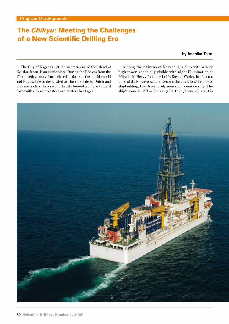
�� Scientific Drilling, Number 1, 2005
The City of Nagasaki, at the western end of the Island of Kyushu, Japan, is an exotic place. During the Edo era from the 17th to 19th century, Japan closed its doors to the outside world and Nagasaki was designated as the sole gate to Dutch and Chinese traders. As a result, the city brewed a unique cultural flavor with a blend of eastern and western heritages.
Among the citizens of Nagasaki, a ship with a very high tower, especially visible with night illumination at Mitsubishi Heavy Industry Ltd.’s Koyagi Works, has been a topic of daily conversation. Despite the city’s long history of shipbuilding, they have rarely seen such a unique ship. The ship’s name is Chikyu (meaning Earth in Japanese), and it is
The Chikyu : Meeting the Challenges of a New Scientific Drilling Era
by Asahiko Taira
Program Developments

Scientific Drilling, Number 1, 2005 ��
The drilling vessel Chikyu cruising offshore Nagasaki during its test cruise in December 2004. The vessel is 210 m long, has 57,500 gross tons displacement, and accommodates 150 people.
Program Developments
the first riser-equipped scientific drilling vessel ever built, with a record height of 122 m from the bottom of the hull to the top of the derrick (http://www.jamstec.go.jp/jamstec-e/cdex/earth/). The ship is truly a blend of worldwide technologies. For example, the hull, engines, and dynamic positioning system were manufactured in Japan, the drilling facilities came mostly from Europe, and the riser pipes were made in the U.S.A. Much like Nagasaki, this ship is a blend of international heritages.
The plan for building a new scientific deep-sea drilling vessel in Japan started more than ten years ago. The Japan Agency for Marine-Earth Science and Technology ( JA MS T EC) took leadersh ip for t h is projec t , a nd
following numerous domestic and international meetings and workshops, construction started in April 2001. The launching ceremony was conducted in January 2002 at Mitsui Shipbuilding Co.’s Tamano Shipyard. The ship then sailed to Nagasaki for further outfitting and underwent the final phases of commissioning and testing of its various systems during mid 2005.
The Chikyu is designed to drill deeper than ever before beneath the deep-sea f loor. The target was set to drill to 7000 m, in water depths initially up to 2500 m, eventually up to 4000 m. To ensure borehole stability, remove rock cuttings, and prevent gas or water blow-outs, heavy, muddy drilling f luid must be circulated through the borehole between the ship and the bot tom end of the dril lbit . Deployment of riser pipes that enable the confined circu-lation of this heavy mud is the key technology of the Chikyu. The ship is required to remain stationary for a long time at sea against wind, waves, and currents. This stability is achieved by six powerful computer-controlled thrusters with 360-degree, screw-axis rotation capability. Robotic and automated drillpipe handling systems ensure a safe and efficient working environment.
T he Chikyu houses advanced and comprehensive scientific research facilities. Four stories of laboratories and living quarters with an array of tools and equipment provide space for fifty scientists and technical support staff. With synergy between state-of-the-art technology and the enthusiasm of researchers and engineers, the Chikyu is prepared to push the frontiers of scientific drilling into the deep unexplored biosphere, into depths where mantle rocks deform, into the seismogenic zone where strain energy for mega-earthquakes responsible for huge tsunamis is accumulated, and where the unread records of Earth’s history are archived.
After the delivery in late July of this year, JAMSTEC’s Center for Deep Earth Exploration (CDEX) has taken responsibility for ship operations. The current plan calls for two years of testing and training offshore of northeastern Japan; the Chikyu operations will then be fully incorporated into the Integrated Ocean Drilling Program (IODP) in late 2007. The voyage of the dilling vessel Chikyu, seeking out and expanding new frontiers in science, technology, and international collaboration, is about to begin.
AuthorAsahiko Taira, Director-General, Center for Deep Earth Explorat ion, Japan Agency for Marine -Earth Science and Technology, CDEX OD21 Program Department, 2-15 Natsushima-cho, Yokosuka, Japan 237-0061, e-mail: [email protected]
Figure CreditPhoto courtesy of Japan Agency for Marine-Earth Science and Technology (JAMSTEC).

�� Scientific Drilling, Number 1, 2005
The JOI Alliance is operating the riserless drill ing vessel contributed by the United States to the Integrated Ocean Drilling Program (IODP). Currently, the alliance, consisting of the Joint Oceanographic Institutions Inc. (JOI), and its partners, the Lamont-Doherty Earth Observatory of Columbia University (LDEO) and Texas A&M University (TAMU), is operating the drilling vessel JOIDES Resolution, widely known for her many years of service to the Ocean Drilling Program.
During the initial stage of IODP, a new slate of drilling expeditions and a request for proposals to design and supply a new state-of-the-art riserless research vessel have generated numerous challenges and opportunities. A lthough a hiatus in r iserless dril l ing was originally planned for 2005, the IODP responded to the challenge of quickly planning a schedule of expeditions for the full calendar year on topics ranging from f luids circulating beneath the seafloor to the formation of methane hydrates. Parallel efforts to obtain a new drillship are underway, with progress being made on design specifications, selection
of a vessel contractor and obtaining funds from the U.S. National Science Foundation (NSF).
�00� ExpeditionsThe IODP began 2005 on the JOIDES Resolution with
Expeditions 304 and 305 to examine the formation of oceanic core complexes. Expedition 306 focused on the climate history of the North Atlantic Ocean. In late April– May, Expedition 307 obtained samples from carbonate mounds from the Porcupine Basin of fshore Ireland to examine the microbiological and biogeochemical processes that affect the formation and development of these mounds. On these sites, topped by dead cold-water corals, particular emphasis was placed on the role of environmental factors and fluids as a growth trigger. Expedition 308 followed in the Gulf of Mexico and provided information on overpres-sured f luids beneath the seaf loor and interactions of sedimentation, fluid migration, and structural deformation. Expeditions 309 and 312, Superfast Spreading Rate Crust 2 and 3, will attempt to sample a complete section of the upper oceanic crust formed at a superfast (>200 mm yr-1)
Program Developments
New Opportunities in Riserless Ocean Drilling
by Kasey White
JOIDES Resolution rounds the Ponta Delgada Lighthouse on its way in from Expedition 305.

Scientific Drilling, Number 1, 2005 ��
Program Developments
spreading ridge. The first of these expeditions took place in July–August and the second will take place October to December 2005. If successful, this will be the first sampling of a complete section of oceanic crust from extrusive pillow basalts, through sheeted dikes, and into gabbros, and it is expected to define interactions between magmatic, hydro-thermal, and tectonic processes. As part of an ongoing effort to understand climate change and the possible links to the resource potential of gas hydrates, Expedition 311 in late 2005, will study the deep origin of methane on the Cascadia Margin, its upward transport, its incorporation in gas hydrates, and its subsequent loss to the seafloor. IODP plans to demobilize the JOIDES Resolution after Expedition 312 in January 2006, and awaits her replacement for resumed riserless drilling in 2007.
Future PossibilitiesPlans are under way to obtain and configure a riserless
drillship that will be able to meet the long-term science objectives of the IODP, relating to research of the deep biosphere and subseafloor ocean, environmental change, and solid Earth cycles. Although the JOIDES Resolution, has performed admirably for the ODP and the IODP over the past 20 years, new laboratory space and facilities and drilling capabilities are needed to conduct cutting-edge research in the 21st century. A briefing book presenting a vision for a riserless platform as articulated by the scientific community through meetings and reports is available online at http://www.joialliance.org/MREFC/briefing_book/. The
book encompasses drilling and coring capabilities, onboard scientific research capabilities, and issues of habitability.
The JOI Alliance released a request for proposals for a new drilling vessel in October 2004, and responses were due in February 2005. The review process for selecting a company to conduct the conversion and subsequent opera-tions is ongoing, with an award expected before the end of 2005. The United States, through the NSF, is funding the conversion. In December 2004, President Bush signed into law an appropriations bill that provided the first funds ($14.88 million) to begin the process. These funds will be used to place orders for long-lead-time drilling equipment, detailed engineering design documents, and drawings for the ship conversion package. The president has requested $57.92 million for the coming fiscal year, with a projection to request $42.2 million in fiscal year 2007. Those funds will be used for converting the ship, installing the science system, and sea trials. With appropriations forthcoming, the JOI Alliance seeks to begin expeditions on the updated ship in 2007.
AuthorKasey White, formerly with Joint Oceanographic Institu-tions, Washington DC, U.S.A., current address: Center for Science, Technology and Congress, American Association for the Advancement of Science, 1200 New York Ave., Wash-ington DC 20005, U.S.A., e-mail: [email protected]

�� Scientific Drilling, Number 1, 2005
When the British Geological Survey (BGS) compiled the consortium bid that later translated into the European Consortium for Ocean Research Drilling (ECORD) Science Operator (ESO) for the new Integrated Ocean Drilling Program (IODP), we stated that mission-specific platforms (MSPs) would introduce a fundamentally new dimension into scientific ocean drilling. Although this belief was based on our collective involvement in similar-type expeditions in various parts of the world, little did we realize just how much of a new dimension it was going to be for the operator as well as IODP management, scientific panels, proponents, and participants.
With the IODP Expedition 302, Arctic Coring Expedition (ACEX), now behind us, we question whether it set a pattern as the first of the MSP operations. In this article we compare ACEX to the current work we are engaged in, preparing for IODP Expedition 310, Tahiti Sea Level. It indicates how different and individual each MSP expedition will be—just as the name implies.
ACEX had a long gestation through various planning groups before the ESO inherited it, and without the head start that this provided, we would not have been able to conduct the expedition in 2005; It was a learning experience for the program fully to realize, however, that for MSP operations there is no firm plan before that plan is in place by way of signed and secured contracts with companies or contractors able to do the work. This is an issue with which we still grapple: how do we cope with commercial practices, legal tendering, and contractual issues while at the same time keep an eager science community fully informed about the status and likely logistics of the expedition? This is very different from the routine of the Ocean Drilling Program (ODP), where the vessel, on a continuous rolling contract, was always known, the timings for port calls were firmly fixed, and each project was allocated one leg of eight weeks. Also, it is fair to say that funding, which always will be an important issue to be taken into account, has a particular strong impact on field time available for a given MSP operation. Preparations for Tahiti are coming up against similar time constraints in decisions for contracting and disseminating specific information, including timing of operations to the wider scientific community, because tenders and contractual issues have yet, as of July 2005, to be completed. This places the program in a delicate balancing position regarding information dissemination,
community discussion, and decision-making. It also places a strong requirement on the scientists to stick to the original specification as far as possible, because each change means compromise to fit all within predetermined budgets.
ACEX put into effect operations to meet the science requirements for a highly ranked drilling proposal in a high polar environment. Some aspects were special to that particular environment, but others will reoccur in every MSP operation. A key issue for the MSP operations is the fact that there is no single MSP vessel for the IODP. The ESO prepares an outline specification from operational information and prepares a call for interest from suitable contractors. This is followed by a detailed specification and tender process based on responses to the expressions of interest. Both of these operations have to be conducted in accordance with European Union regulations on fair compe-tition and a legally binding timescale. Only after all of these legal requirements are put into effect is funding confirmed from the ECORD and the IODP. Then contracts are signed, the detailed equipment and operations planning come into play, and the scientists can be fully informed of the forth-coming project in terms of timing, drilling, and laboratory facilities. This means that within the scope of each project there is the procurement of a suitable platform or vessel, a technical plan for execution of the science, a mobilization of all equipment and personnel, and then the project execution. Upon completion, the whole apparatus is dismantled.
This concept was (we hope) at one extreme end of the spectrum for ACEX. No Arctic-class icebreaking drilling vessel suitable for the work was available, and additional support icebreakers also had to be contracted, together with specialist services, in order to undertake the work.
A North Sea anchor handling and supply boat with Baltic-class icebreaking capability (the Vidar Viking) was contracted in January 2004 for work commencing at the end of July 2004. A moonpool was designed as part of the contract and installed in May 2004 during a routine dry dock. At the same time, a drilling contractor, Seacore Ltd., of Cornwall, U.K., was chosen to design, build, and operate a suitable rig and associated machinery for instal-lation on the vessel. The ESO worked with the U.S. imple-menting organization at Texas A&M University to obtain drillpipe and build transportation containers in Houston, Texas, U.S.A. that ultimately became the drill floor for the
Program Developments
From the North Pole to Tahiti—Initial Experiences with IODP and MSPs
by Alister Skinner and Dan Evans

Scientific Drilling, Number 1, 2005 ��
operation. Both companies and the ESO worked closely together with advisors from the regulatory authorities. Captain Anders Backman was already identified as our Fleet Master, to ensure that the agreed workflow and timelines were met. While all this was occurring, the ship continued working on other projects until the last quarter of July 2004, when the mobilization commenced in Aberdeen, Scotland. Only at this stage did the day rates for the designated drilling vessel commence.
Also, in the closing weeks of January and into February, an agreement was signed with the Swedish Polar Research Secretariat for provision of the icebreaker Oden, ice management, helicopter, medical services, a nd t he R uss ia n nuclea r icebrea ker, Sovetskiy Soyuz. All vessels had different contracts and places for on and off hire. The Vidar Viking was chartered from Aberdeen to Aberdeen, the Oden from Gothenberg to Stockholm, and the Sovetskiy Soyuz from and to the ice edge, somewhere north of Norway, but with an agreed meeting date of all vessels at the ice edge on 10 August 2004.
During a period of six days in late July, the Vidar Viking
was transformed from a bare boat into a drilling vessel by addition of the rig, mud system, drill floor, workshops, logging unit, petrophysics container, and core containers
(Figs. 1 and 3). After sailing and testing the equipment in the North Sea to ascertain that all systems were functional, the vessel continued to Landskrona, Sweden, where the vessel’s stern notch for working in ice, the helideck, and the curation laboratory from Bremen University (Germany) were installed. The stern notch and helideck are removed for North Sea
operations and are routinely installed on the vessel as the ship returns to the Baltic Sea for winter icebreaking duties.
Before sailing from Landskrona, the Vidar Viking was fully transformed into an Arctic-capable drillship—all in a space of eleven days. The Vidar Viking met up with the Oden at a brief port call in Tromsø, Norway, and the science party embarked. The Russian escort joined the fleet a few days later, at the ice edge on 10 August 2004 as planned. This was the perfect culmination of a very busy schedule to meet the weather window available for the Arctic work.
On a normal drilling expedition, the next step would be to get on site and start drilling. Arctic conditions put a different slant on this. First, we had to be escorted to site, f ind a suitable ice-management plan for staying on location, remove all ice which had accumulated in the moonpool on transit (Fig. 2), fit the ice protection
Program Developments
Figure 1. Drilling on a sunny day in the Arctic.
Figure 2. Clearing the moonpool to start work at the first site.

�� Scientific Drilling, Number 1, 2005
skirt into the moonpool and below the hull to protect the drillstring, and then try to position on site. Within hours it was established that dynamic posit ioning could not be ut il ized, because the conditions were much harsher than anticipated, and the drillship would also have to break ice. For the next three weeks, the captain and mates demonstrated their expertise in the art of seamanship and station keeping by traditional methods, albeit using some of the advantages of modern technology, while the Oden and the Sovetskiy Soyuz did a fantastic job around the Vidar Viking, mincing the ice f loes into manageable, bite-size portions most of the time.
The Vidar Viking was too small to host the drill ing operation and the science party (Fig. 3). The Oden became the nerve center for ice and scientific operations, with scheduled personnel transfers between vessels as required. Furthermore, only a subset of the full science party sailed on the expedition. Cores were not split on board. The main scientific component of the expedition took place at the University of Bremen after the expedition was completed and the cores sent ashore for examination by the full scientific party.
With close monitoring of the budget (for example, fuel costs alone varied from $6000 to a maximum of $30,000, depending on operat ions), the t ime for science was maximized within the available resources. On completion, the ships left the ice, and this signaled the commencement of demobilization. The Sovetskiy Soyuz came off charter at the ice edge and the Vidar Viking disembarked some
personnel to the Oden, which headed for Tromsø to disembark all scien-tists and ESO-contracted personnel. The Oden then made onward transit to Stockholm for the end of her charter while the Vidar Viking made all speed to the southern coast of Norway, for a ship’s crew change and demobilization of the drill rig. The Vidar Viking then continued to Landskrona with a reduced ESO and Seacore crew to remove the stern notch, helideck, cores, and curation laboratory, and to reinstall the chain locker instead of the moonpool (Fig. 4). The final stage of demobilization took place in Aberdeen, where the remainder of the Seacore, ESO, and Schlumberger equipment was removed.
A f ter ACEX, it appeared that Expedition 310 to Tahiti would be a much more straightforward project
Program Developments
Figure 3. A cold evening – view onto the work deck of the Vidar Viking.
Figure 4. The moonpool returned to a chainlocker at the end of demobilization.

Scientific Drilling, Number 1, 2005 ��
in an easier area for logistics and opera-tions, but, experiences so far suggest that there are equal but different challenges in store! Unlike the ACEX expedition to the Arctic, where the physical environment posed very strong limitations on the avail-ability of suitable platforms, the soaring-price of oil in 2005 led otherwise interested vessel contractors to direct their f leet to the most booming markets. This made it extremely difficult to contract a suitable vessel for Tahiti at a price that would allow enough time on location to address the planned science. So despite tendering for drilling platforms and drilling contract as timely as possible, only as of very late July this year was it possible to complete a contract for a suitable drilling vessel for the Tahiti expedition planned to start in late September 2005. The vessel selected, with the help of the drilling contractor Seacore, is the dynamically positioned vessel Hunter (Fig. 5). The Hunter will offer ample space for the drilling equipment and good accommodation and working facilities for the seagoing part of the science party.
The expedition’s close proximity to land, however, means that drilling permits and clearances are required, and coring in a coral reef environment requires an environmental impact assessment (Fig. 6). There are navigational issues surrounding the operation, such as potential interference with the international airport and navigation channel for the main port, Papeete, which are close to one area of work. A small, remotely operated vehicle (ROV) or camera system is likely to be required for pre- and post-drilling monitoring
of the sites. Until the vessel selected from tender was under contract, no further action could be taken on many of these issues. International legal requirements mean that the vessel owners are responsible for obtaining diplomatic clearances through the f lag state of the selected vessel. Thus, ESO cannot prepare final equipment scenarios until the contractor and ship capability is fully known.
Rest assured, however, that ESO will always endeavor to overcome the challenges offered by MSP drilling and pursue the unique opportunities MSP operations provide IODP scientists for accessing dif f icult , yet important drilling locations, the challenge being water depth, sea ice, or fragile formations like carbonate reefs.
AuthorsAlister Skinner and Dan Evans, ECOR D Science Operator (ESO) a nd Br i t ish G eolog ic a l Sur vey, British Geological Survey, Marine O p e r a t i o n s a n d E n g i n e e r i n g , Murchison House, West Mains Road, Edinburgh EH9 3LA, Scotland, U.K., e-mail: [email protected]
Related Weblink http://www.ecord.org/exp/tahiti/ 310.html
Program Developments
Figure 6. A potential drilling site of IODP Expedition 310 offshore Papeete (Tahiti).
Figure 5. The dynamically positioned vessel Hunter will be used for drilling in Tahiti.

�0 Scientific Drilling, Number 1, 2005
IntroductionIn 1994, a group of scientists began discussing a number
of important scientific questions that could be addressed by drilling a series of short cores on the Antarctic conti-nental shelf. The group adopted the name SHALDRIL, for SHALlow DRILling, and soon learned that the technology for high-quality sampling of the upper few hundred meters of the stratigraphic column was still lacking.
After more than a decade of discussion and several years of detailed planning, SHALDRIL sailed from Punta Arenas, Chile, in March 2005. The objectives of this first SHALDRIL cruise are to demonstrate the feasibility of drilling from an icebreaker platform into the Antarctic continental shelf and to obtain cores from three different sedimentary sequences that previously have not been sampled.
The principal objective of SHALDRIL originally was to monitor technological developments in shallow drilling from conventional icebreaking research vessels. In 2000, the SHALDRIL steering committee learned about new and improved drill ing systems that can core through gravelly glacial deposits in water depths of several hundred meters and to subbottom depths of a few hundred meters (SHALDRIL Steering Committee, 2001). These systems can be operated from the icebreaking research vessel
Nathaniel B. Palmer (Fig. 1); thus, the long-term project has now entered the next phase of testing this proven drilling technology aboard a U. S. Antarctic Program vessel.
TechnologyIn 2003, a contract was signed with Seacore Ltd. (U.K.)
to conduct the drilling operations for SHALDRIL. This choice was made after evaluating all of the companies then operating shallow coring systems, and it was based on the capabilit ies of heave-compensated rig systems, sampling tools, mobility, availability, and cost. The rig built for SHALDRIL is called the R-50 (Fig. 2) and is similar to, but slightly smaller than, the rig used recently on IODP Expedition 302 in the Arctic (ACEX), also built by Seacore. The rig is completely modular and can be rapidly mobilized as container freight. The rig has the capacity to take 100 m of core in up to 1000 m of water and longer cores in shallower water. The SHALDRIL rig has a 3 -m heave compensator that will allow drilling to continue in any type of seas in which people can realistically work, and it will be mounted over a moonpool in the starboard deck of the Palmer (Fig. 3). The position of the rig close to midship will help minimize heave as compared to drilling over the stern. The moonpool will protect the drillstring from stray bits of floating ice and will ensure that ice does not accumulate in the moonpool during drilling.
The Inaugural SHALDRIL Expedition to the Weddell Sea, Antarctica
by Julia S. Wellner, John B. Anderson, and Sherwood W. Wise
Reports from Related Programs
Figure 1. The Nathaniel B. Palmer in ice.
doi:10.��0�/iodp.sd.1.0�.�00�

Scientific Drilling, Number 1, 2005 �1
T he process of plann ing to install the R-50 rig onto the Palmer brought with it many unexpected problems. The major hurdle was that the rig adds so much mass at heights above deck that the vessel would not meet damage-stability criteria defined by the U.S. Coast Guard. A fter analyses by several naval architects and tests performed on the ship, additional ballast was installed to allow the R-50 rig to be safely mounted on board.
The sampling tools for SHALDRIL are being provided by the British Geological Survey (BGS) through a subcontract to Seacore. Most of the tools that will be used are part of the older BGS system, not the new tools used as part of ACEX. Piggyback coring hardware may be used in harder litho-logies, although it is not the preferred technology for this program because of the time required to pull out of a hole and the likely presence of icebergs in the area. The other
sampling tool available for SHALDRIL is a Shelby-tube system especially modified for this cruise to accept liners and allow higher quality sampling of very soft materials.
The Palmer was not designed with drill ing in mind and had to have its positioning system upgraded to make open-water drilling feasible. These upgrades have included the lease of a differential Global Positioning System (GPS) from Fugro-McClelland, the purchase of a single-seafloor-beacon relative positioning system, and new software for ship handling. The vessel now meets dynamic positioning (DP) system Class 0 criteria. The system has been tested, at least in part, but its full functionality will be used for the first time during SHALDRIL. The SHALDRIL strategy of taking a series of relatively short drill cores (~100 m each) is based in part on the limits of ship handling, as well as on the unavoidable fact that icebergs may limit time at any one station.
The 31 March 2005 start date is far later in the austral summer season than ideal, but resulted in part f rom technical obstacles such as the need to modify the ship structurally, as well as the general demands for ship time from many different parties. Years ago, the SHALDRIL group discussed planning the project for the austral winter or close to it, and using fast ice to stabilize the vessel. Knowledge gained from other high-latitude drilling opera-tions and from DP specialists led the program away from this option in favor of open-water drilling operations. Fast ice could stabilize the ship and might still be used in some cases, but relying on the right ice conditions (truly fast ice without any movement over many days, yet still thin enough to allow entry and safe exit) is riskier than relying on open water.
Scientific ObjectivesThe area best suited for this phase of the program is the
James Ross Basin, located in the northwestern Weddell Sea region, offshore of Seymour Island (Fig. 4). This is the area initially identified by the SHALDRIL group as having shallow drilling targets of great scientific value, existing
Reports from Related Programs
Figure 2. The R-50 rig assembled in the Seacore yard in Cornwall.
Figure 3. Schematic showing a drill rig placed over the moonpool on the Nathaniel B. Palmer.

�� Scientific Drilling, Number 1, 2005
Reports from Related Programs
site-survey data, closest proximity to ports of departure and return, and proximity to auxiliary sites of scientific value.
The principal objective of this initial drilling leg is to test the drilling system using the Nathaniel B. Palmer, but the acquired core will have high scientific value. The first hole will be drilled into the Vega Drift (Fig. 4), an expanded section of Holocene deposits. This site was selected as the first to be drilled because it lies in the deepest and most protected water and, hence, is logistically the most feasible for testing the new drilling system. The Vega Drift site is the closest to shore and the most protected from inclement weather that typically moves eastward across the Antarctic Peninsula before reaching the drilling area. The lithology at this site, however, may be more difficult to sample with the standard suite of tools. Relatively soft, diatomaceous muds and occasional gravelly dropstones are expected throughout the total estimated coring depth of 100 m. The modified Shelby-tube sampler was designed for this site to obtain the high-quality core needed to construct a detailed record of high-frequency climate change that can be compared to those from elsewhere in the region, such as the Palmer Deep on the western margin of the Antarctic Peninsula (Domack et al., 2001).
The second drilling site targets Tertiary strata that should record climate change and the associated faunal and floral changes as the cryosphere evolved in the Antarctic Peninsula region. This site is intended to sample the acous-tically layered strata that occur immediately downdip of
Seymour Island (Fig. 4). These strata lie below a major unconformity predicted to mark the boundary between preglacial sediments and overly ing strata that show abundant evidence of glacial inf luence. Seismic stratig-raphy and correlative strata exposed onshore suggest that this sequence should consist of upper Eocene through Oligocene strata. The onshore strata are extremely fossil-i ferous (Zinsmeister et al., 1989), and the more distal offshore strata should provide greater details about the faunal and f loral changes that occurred as the Antarctic ice sheet grew larger, closing the last ice-free refugia at the northern tip of the Antarctic continent. Paleontological analyses of the uppermost part of this section will provide age constraints on the onset of glaciation. The sites planned for SHALDRIL’s second season lie further updip towards Seymour Island (Fig. 4). They will sample the overlying glacially influenced section and will further constrain the timing of the expansion of the ice sheet. To obtain the best possible paleontologic record from each of these Neogene targets, SHALDRIL aims to sample the glacial-marine units, as identified by seismic facies, rather than the uncon-formities themselves.
The third hole to be drilled in 2005 targets a Pleistocene grounding-zone wedge and its record of ice flow during the last glacial maximum. We currently lack data for studying the processes by which sediments deform under ice sheets. It is extremely difficult to obtain core samples of modern till because of the extreme thickness of ice moving over that till; however, the previously ice-covered Antarctic conti-
Figure 4. Map of the James Ross Bas in area showing planned drilling sites for 2005 and those proposed for season two.

Scientific Drilling, Number 1, 2005 ��
Expedition UpdateThe first SHALDRIL cruise ended on 23 April 2005.
Due to unexpected weather conditions, the first drilling site was moved to Maxwell Bay in the South Shetland Islands. A Holocene section of 108 m of core was recov-ered there, which will allow insights into the climate changes that have occurred at the tip of the Antarctic region. Due to the cruise being well past the optimal season, storms and ice were encountered. Weather conditions as well as some equipment bugs prevented recovery and sampling of the older sections this year. However, experience gained during this cruise will prove to be valuable planning for the next expedition in 2006. Readers interested in the full cruise report, may request it by e-mail to Julia Smith Wellner ( [email protected]).
Reports from Related Programs
nental shelf provides an ideal place to obtain such samples. The succession within the upstream portion of a wedge should contain changes in ice–bed interaction, from the initiation of bed deformation and streaming to the retreat of the ice stream. A spectacular grounding-zone wedge from the last glacial maximum occurs near the seafloor in close proximity to the other drilling sites (Fig. 4). Coring glacial diamictons is notoriously difficult, but the sampling apparatus that we are bringing for SHALDRIL should be able to recover the first high-quality, long core samples of a grounding-zone wedge deposit.
Ice conditions might not allow drilling at any of these sites, but the entire continental shelf around the Antarctic Peninsula is being considered for alternate sites. Seismic data can be collected during the drilling cruise if needed for selecting alternate sites.
Future PlansOver the last few years, the SHALDRIL group has
encountered more difficulties than ever imagined in trying to bring together the technologies of an icebreaker and a shallow coring system. We have had to improvise and learn as we go; however, we believe that we have overcome as much as possible and can l ive with the remaining difficulties.
SH A LDR IL wil l complete its f irst leg on 23 Apr i l 2005. Assuming that we succeed at bringing back core, a workshop will be held at the Antarctic Research Facility in Tallahassee, Florida (U.S.A.) in August 2005, to display the cores to the scientific community and invite proposals for studying them. Either way, we expect to sail again soon on SHALDRIL II to complete the drilling offshore James Ross Island.
For more information, including daily postings from the cruise, please see http://shaldril.rice.edu/.
AcknowledgementsOther sc ient ist s cur rent ly involved in th is f i rst
SHALDRIL cruise include S. Bohaty, P. Manley, F. Weaver, and J. Zachos. We thank the dedicated staff at Raytheon Polar Services Company for helping to make SHALDRIL possible. We are supported by the U.S. National Science Foundation Office of Polar Programs.
References
Domack, E., Leventer, A., Dunbar, R., Taylor, F., Brachfeld, S., Sjunneskog, C., and ODP Leg 178 Science Party, 2001. Chronology of the Palmer Deep site, Antarctic Peninsula: a Holocene paleoenviron-mental reference for the circum-Antarctic. The Holocene, 11:1–9.
SHALDRIL Steering Committee, 2001. SHALDRIL: A Shallow Drilling System to Investigate Antarctica’s Climate History: Tallahassee (AMGRF, FSU).
Zinsmeister, W.J., Feldman, R.M., Woodburne, M.V., and Elliot, D.H., 1989. Lower Cretaceous/early Tertiary t ransit ion on Seymour Island, A ntarct ica . J. Paleontol., 63:731–738.
AuthorsJ. S. Wellner, Department of Earth Science, Rice Univer-sity MS-126, 6100 Main Street Houston, TX 77005, U.S.A., e-mail: [email protected]
J. B. Anderson, Department of Earth Science, Rice Univer-sity MS-126, 6100 Main Street Houston, TX 77005, U.S.A.,
S. W. Wise, Department of Geological Sciences, 108 Car-raway Building, Florida State University, Tallahassee, FL 32306-4100, U.S.A.
Figure CreditsFig. 1 photograph from http://www.polar.org/science/marine/images/nbp_images/ship_cape_royds.jpg.Fig. 2 Photo by A. Lowe.All other figures courtesy of SHALDRIL.
Related Weblinkhttp://shaldril.rice.edu/
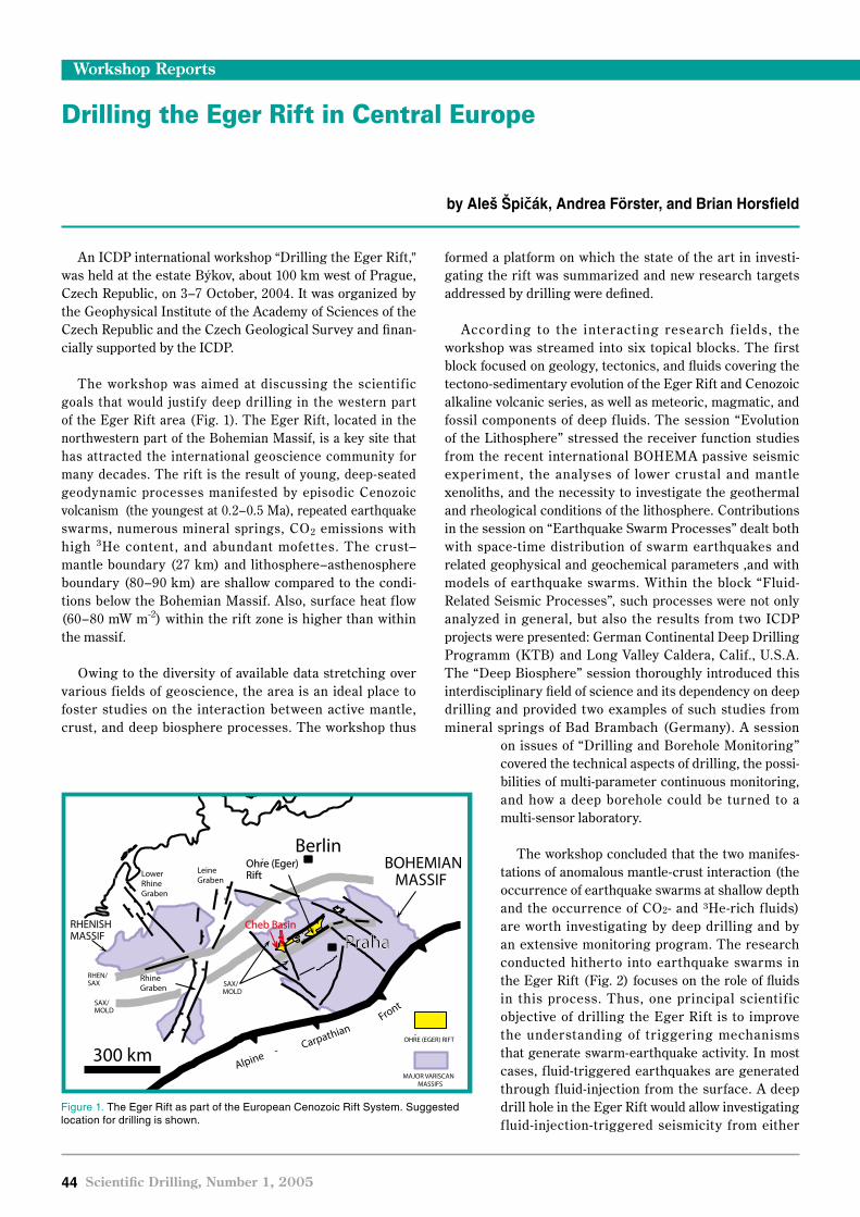
�� Scientific Drilling, Number 1, 2005
An ICDP international workshop “Drilling the Eger Rift,” was held at the estate Býkov, about 100 km west of Prague, Czech Republic, on 3–7 October, 2004. It was organized by the Geophysical Institute of the Academy of Sciences of the Czech Republic and the Czech Geological Survey and finan-cially supported by the ICDP.
The workshop was aimed at discussing the scientif ic goals that would justify deep drilling in the western part of the Eger Rift area (Fig. 1). The Eger Rift, located in the northwestern part of the Bohemian Massif, is a key site that has attracted the international geoscience community for many decades. The rift is the result of young, deep-seated geodynamic processes manifested by episodic Cenozoic volcanism (the youngest at 0.2–0.5 Ma), repeated earthquake swarms, numerous mineral springs, CO2 emissions with high 3He content, and abundant mofettes. The crust–mantle boundary (27 km) and lithosphere–asthenosphere boundary (80–90 km) are shallow compared to the condi-tions below the Bohemian Massif. Also, surface heat flow (60–80 mW m-2) within the rift zone is higher than within the massif.
Owing to the diversity of available data stretching over various fields of geoscience, the area is an ideal place to foster studies on the interaction between active mantle, crust, and deep biosphere processes. The workshop thus
formed a platform on which the state of the art in investi-gating the rift was summarized and new research targets addressed by drilling were defined.
According to the interact ing research f ields, the workshop was streamed into six topical blocks. The first block focused on geology, tectonics, and fluids covering the tectono-sedimentary evolution of the Eger Rift and Cenozoic alkaline volcanic series, as well as meteoric, magmatic, and fossil components of deep f luids. The session “Evolution of the Lithosphere” stressed the receiver function studies from the recent international BOHEMA passive seismic experiment, the analyses of lower crustal and mantle xenoliths, and the necessity to investigate the geothermal and rheological conditions of the lithosphere. Contributions in the session on “Earthquake Swarm Processes” dealt both with space-time distribution of swarm earthquakes and related geophysical and geochemical parameters ,and with models of earthquake swarms. Within the block “Fluid-Related Seismic Processes”, such processes were not only analyzed in general, but also the results from two ICDP projects were presented: German Continental Deep Drilling Programm (KTB) and Long Valley Caldera, Calif., U.S.A. The “Deep Biosphere” session thoroughly introduced this interdisciplinary field of science and its dependency on deep drilling and provided two examples of such studies from mineral springs of Bad Brambach (Germany). A session
on issues of “Drilling and Borehole Monitoring” covered the technical aspects of drilling, the possi-bilities of multi-parameter continuous monitoring, and how a deep borehole could be turned to a multi-sensor laboratory.
The workshop concluded that the two manifes-tations of anomalous mantle-crust interaction (the occurrence of earthquake swarms at shallow depth and the occurrence of CO2- and 3He-rich f luids) are worth investigating by deep drilling and by an extensive monitoring program. The research conducted hitherto into earthquake swarms in the Eger Rift (Fig. 2) focuses on the role of fluids in this process. Thus, one principal scientif ic objective of drilling the Eger Rift is to improve the understanding of tr iggering mechanisms that generate swarm-earthquake activity. In most cases, fluid-triggered earthquakes are generated through fluid-injection from the surface. A deep drill hole in the Eger Rift would allow investigating f luid-injection-triggered seismicity from either
Workshop Reports
Drilling the Eger Rift in Central Europe
by Aleš Špičák, Andrea Förster, and Brian Horsfield
Berlin
300 km
RhineGraben
RHENISHMASSIF
MAJOR VARISCANMASSIFS
BOHEMIAN MASSIF
LeineGraben
LowerRhineGraben
SAX/MOLD
RHEN/SAX
Cheb Basin
Alpine -Carpat ianh
FrontSAX/MOLD
v
OHRE (EGER) RIFT
Ohre (Eger)Rift
v
Praha
Figure 1. The Eger Rift as part of the European Cenozoic Rift System. Suggested location for drilling is shown.

Scientific Drilling, Number 1, 2005 ��
Figure 2. Schematic 3-D section of the Nový Kostel area. The main epicentral cluster indicated by red surface occurs at depths of 6-11 km below the eastern margin of the Cheb Basin. Triangles indicate seismic stations of WEBNET. EG and MLF denote the main tectonic structures of Eger Rift and Mariánské Lázně Fault.
direction (naturally upward migrating fluids and man-made hydraulic tests) at the same time, which would clearly be a worldwide unique experiment. Furthermore, applying state-of-the-art seismic monitoring techniques would allow performing stress field determinations that could be related to in situ stress field measurements. Such investigations extend the activities addressed by the San Andreas Fault Zone Observatory at Depth (SAFOD) project at Parkfield, Calif., U.S.A., where earthquake triggering is investigated in a completely different tectonic environment at one of the largest transform faults. Besides research on triggered earthquakes, a 6–7-km-deep borehole in western Bohemia would provide a unique possibility to monitor and study the behavior of rocks and fluids from the surface down to the source region of earthquake swarms. Even more intriguing, and what makes the Eger Rift unique as far as ICDP sites are concerned, is the triggering of deep microbial activity by fluid release during the earthquake swarms. Methane is generated as part of this activity, attesting to a coupling of the biosphere and geosphere. Drilling the Eger Rift would provide an exciting opportunity to sample and monitor this fascinating phenomenon.
Minera l spr ings are impor tant for the cont inued prosperity of the surrounding areas (e.g., in Karlovy Vary). The results from the borehole laboratory would help us to
understand better the mechanisms driving the spas, for instance, whether the deep f luid circulation is related to shallow fluids feeding the springs in the spas. This is clearly of great socio-environmental relevance.
At the end of the workshop, a field trip introduced the participants to key sites in western Bohemia including the thermal springs at Karlovy Vary Spa, the potential drilling site in the northern part of the Cheb sedimentary basin (in the vicinity of the seismically dominant Nový Kostel earthquake focal zone), the Bublák mofette (surrounded by seismic stations of the WEBNET (Academy of Sciences, Prague) and KRASNET (Brno University) networks), the CO2 exhalations at Soos, and the Železná Hůrka volcano and its tephra deposits.
AuthorsAleš Špicák, Geophysical Institute of the Academy of Sci-ences of the Czech Republic, Bocni II/1401 14131 Prague 4 Czech Republic, e-mail: [email protected]
Andrea Förster, GeoForschungsZentrum Potsdam, Tele-grafenberg, 14473 Potsdam, Germany
Brian Horsfield, GeoForschungsZentrum Potsdam, Tele-grafenberg, 14473 Potsdam, Germany
Workshop Reports

�� Scientific Drilling, Number 1, 2005
Workshop Reports
One of the greatest successes of the Ocean Drilling Program has been the concerted dril l ing ef forts and exciting results recovered from the Southern Ocean, the very cold and very biologically productive ocean basin surrounding Antarctica. Scientific drilling in the ocean and on the Antarctic margin has recovered material from hundreds of sites for scientif ic analysis. Results from these sites have revealed the dynamic nature of ice-sheet development and ice-margin interactions through time. They also have shown that the Southern Ocean is a critical component in the development and persistence of Antarctic glaciation, a sensitive mixing pool of global water masses, a locus of high biological sedimentation, and that it contains high-resolution records of climate forcing and response; as such, it is one of the most important oceanographic regions in the world. Results from scientific drilling have significantly increased our understanding of Cenozoic to decadal processes that impact the oceanography and climatology of the Southern Ocean and Antarctica. It is now an important time to mine the rich results from scientific drilling over the past several decades, and thus a lso to prov ide a scient i f ic framework for future expeditions in this region.
To this end, twenty-six researchers from five countries were invited to attend a synthesis workshop on the campus of the University of Colorado in Boulder, in January 2005. This synthesis workshop was funded by the U.S. Science Support Program of the Joint Oceanographic Institutions Inc., with a focus on Southern Ocean paleoceanography and paleoclimatology. We began with plenary overview talks about the critical aspects of Southern Ocean development and continued with poster presentations and vibrant discus-sions in breakout groups and the group as a whole. The underlying themes of the discussions focused on extracting the knowns, somewhat knowns, and unknowns of various processes, ranging from ice-sheet development, tectonics, ecosystem dynamics, biogeochemical responses, and Southern Ocean thermal structure, on various timescales.
One fantastic product of this workshop was the synergy of top researchers enjoying top science in a retreat-type atmosphere, with quite a few moments of wonder “Why do we not know that yet?” (not an unexpected occurrence whenever you get a group of scientists in a room—we all see
the unknowns sometimes more clearly than the knowns). The final outcome of this workshop will be a set of synthesis papers to be published as a special issue in a journal focused on the following broad themes:
• Steps in climate evolution in the Southern Ocean during the Neogene
• Bio-, magneto-, and radio-chronology in the Southern Ocean
• Development of Antarctic glaciation, Southern Ocean circulation, and productivity during the Cenozoic
• Comparative integration of Antarctic proximal events with Southern Ocean proxies
• Antarctic margin history.
This collection of papers will serve as a science guide to young and old researchers and will provide a framework for planning f ut ure resea rch a nd sc ient i f ic drilling expeditions to this beautiful, cold, and very critical part of our Earth.
A f ter the dust set t led, what seemed l ike a good idea before the workshop (i.e., conducting a synthesis workshop on a regional or topical theme) has solidified in
my mind at least as imperative for a number of fields related to scientific drilling. Although the push to recover more materials from critical places is what rightfully drives much of the science, mining the physical and intellectual archive resulting from decades of scientif ic drilling is also an important activity that should be encouraged and funded as a priority mission of the program.
The workshop agenda book, including a list of partici-pants and abstracts, can be accessed at http://www.geology.iupui.edu/research/BIOGEOCHEMLAB/index.htm
AuthorGabriel Filippelli, Department of Geology, Indiana Univ.-Purdue Univ. Indianapolis ( IUPUI), Indianapolis, IN 46202-5132, e-mail: [email protected]
Related Weblinkh t t p : // w w w . g e o l o g y . i u p u i . e d u / r e s e a r c h / BIOGEOCHEMLAB/
Paleoceanography and Paleoclimatology of the Southern Ocean: A Synthesis of Three Decades of Scientific Ocean Drilling
by Gabriel Filippelli

Scientific Drilling, Number 1, 2005 ��
InterMARGINS
InterMARGINS is an international and interdisciplinary initiative concerned with all aspects of continental margin research. The main purpose is to encourage scientific and logistical coordination, with particular focus on problems that cannot be addressed as efficiently by nations or insti-tutions acting alone or in limited partnerships. During the last months, InterMA RGINS paid much attention to the Sumatra Earthquake and Indian Tsunami issues. InterMARGINS recognizes that tsunami research is very important not only for international science communities, but also for the general public. International collaborations in this field should be promoted proactively. In the future, InterMARGINS is going to tighten its links with the interna-tional community to promote research in the field of conti-nental margins and collaborations with international science programs such as the Integrated Ocean Drilling Program (IODP) and International Continental Scientific Drilling Program (ICDP). InterMARGIN’s activities, latest initiative information such as cruise and workshop reports, and the direction of continental margin-related science are now available on the Web. Please visit http://www.intermargins.org for more information about InterMARGINS.
Important: The InterMARGINS secretariat has rotated from the Southampton Oceanography Centre, Southampton, U.K. to the Japan Agency for Marine-Earth Science and Technology (JAMSTEC), Yokosuka, Japan. The new chair of the InterMARGINS Steering Committee is Dr. Wonn Soh. The new contact address is:
Dr. Wonn Soh
Institute for Research on Earth Evolution (IFREE).Independent Administrative Institution,Japan Agency for Marine-Earth Science and Technology (JAMSTEC)2-15, Natsushima-cho, Yokosuka 237-0061, Japan
News and Views
IODP Site Survey Data Bank Moves to Scripps
Following a competitive request for proposals, the new IODP Site Survey Data Bank (SSDB) will be located at the Scripps Institution of Oceanography. The current SSDB at the Lamont-Doherty Earth Observatory (LDEO) officially closed at the end of May 2005. Personnel at the LDEO SSDB have kindly offered to help in the transition phase to a new electronic data bank, but new data submissions to the LDEO data bank will not be accepted.
The IODP-MI would like to take this opportunity to thank the SSDB people at the LDEO for many years of legendary service to the community and their continued commitment to help with the transition to a new-generation data bank. On behalf of the entire user community: THANKS!
The new IODP Site Survey Data Bank will be fully electronic and web-based. The full announcement can be found on the IODP Web page (http://www.iodp.org/index.php?option=com_content&task=view&id=160&Itemid=170). Questions about the new site survey data bank can be sent to: [email protected].
ICDP Training Course 2005 in Iceland
The ICDP Training Course 2005 will take place in Iceland in cooperation with the Iceland Deep Drilling Project (http://www.icdp-online.org, http://www.iddp.is). The main emphasis this year will be “Hard Rock Drilling” and “Drilling of Geothermal Wells.” ICDP ’s Operational Support Group conducts annual training on scientif ic drilling at an active drilling site. The Training Course 2005 is scheduled for 15–19 August 2005.
IODP Web Portal Relaunched
Besides a completely new look and feel, the newly designed IODP homepage includes many notable new features. Among them are links to numerous IODP national offices and program partners, a news and media center, a subscription page for the IODP-MI newsletter, access to program information generated in Japan, Europe, and the United States, and an integrated, hyperlinked calendar for IODP events, meetings, expeditions, and other program elements. Ongoing Web development wil l result in a powerful search engine that will enable visitors to locate IODP scientific papers, scientists, and program elements globally. For more information on the IODP Web portal contact: Nancy Light, IODP-MI Director of Communications ([email protected]) or go directly to http://www.iodp.org.

�� Scientific Drilling, Number 1, 2005
Current and Upcoming ICDP Drilling Projects
News and Views
The Lake Qinghai Scientific Drilling Project began operations in May 2005 in China. The Satellite Image shows Lake Qinghai and the surrounding mountain ranges of the nor theastern T ibet an Plateau with the planned drilling sites (http://qinghai.icdp-online.org).
ICDP began NSF funded lake drilling operations on Lake Malawi, A frica, in March 2005. A modified local barge with mounted heave-compensated drill rig and four 360˚ outboard thrusters for station-keeping was used to drill up to 380 m sediment core with >95% core recovery in almost 600 m water depth (http://www.icdp-online.org).
Lake Qinghai Scientific Drilling Project
Lake Malawi, Africa

Scientific Drilling, Number 1, 2005 ��
News and Views
Testing Fundamental Theories of Earthquakes and Faulting: The San Andreas Fault Observatory at Depth (SAFOD) in Parkfield, Calif., U.S.A. moves into Phase 2 with directional drilling into the fault zone. During the summer of 2005 the borehole is expected to pass through the entire fault zone (http://safod.icdp-online.org).
With a 2 .2 -km-deep dr i l lhole, the Chesapeake Bay Drilling Project aims to penetrate the central crater of a 35 -My old impact structure in the eastern United States during August to November 2005 (http://cheasapeake.icdp-online.org).
San Andreas Fault Observatory at Depth
Chesapeake Bay Drilling Project

�0 Scientific Drilling, Number 1, 2005
Since 1968, the Deep -Sea Drill ing Project (DSDP) and the Ocean Drilling Program (ODP) have recovered and stored approximately 300 km of core. Half of every core has been kept as an archive, normally only available for viewing. These archive half-cores are well suited for automated non-destructive geophysical measurements (core logging), including many parameters that provide essential data for reconstructing Earth’s climatic history, such as high-resolution magnetic susceptibility, natural gamma spectroscopy, and UV/VIS/IR spectrophotometry.
We recently used a Geotek MSCL -XYZ core logger at the IODP West Coast Repository to log archive core halves recovered by the Glomar Challenger in 1983. The MSCL-XYZ system is specifically designed to allow multi-parameter, non-destructive geophysical data to be collected easily at high spatial resolutions on up to nine split-core sections between reloading. This enables the machine to be loaded and run unattended for periods of many hours (including overnight and weekends), making it well suited for logging of archive core in a repository environment. The immediate goal was to obtain a high-resolution paleo-climate record for DSDP Site 594, east of New Zealand in the Southwest Pacific, but our underlying intention was to open up the vast reservoir of paleoclimate and other data that await extraction from well-preserved archive-half cores from the previous scientific ocean drilling programs, and now in IODP custody.
New Data From Old DSDP Site ���We obtained complete data sets of natural gamma,
magnetic susceptibility, spectral color and RGB digital line scan images from the top 150 m of the sediment column at DSDP Site 594 using the MSCL-XYZ (Fig. 1). This has provided high-resolution climatic data from cores where no core or downhole log data were previously available (Kennett et al., 1986). The cores show striking alterna-tions of calcareous biopelagic and terrigenous muds that represent, respectively, warm interglacial and cold glacial conditions (Griggs et al., 1983; Nelson et al., 1993; Carter and Gammon, 2004), with typical sedimentation rates at Site 594 of 10 cm ky-1 (biopelagic) and 16 cm ky-1 (terrigenous; Kennett et al., 1986). Natural gamma was of primary interest and was collected at 5 -cm intervals (nominal resolution 300–500 yr). To our knowledge, this is the first time that a high-resolution natural gamma data log has been recovered from an archive core half. Magnetic susceptibility data and color spectrophotometer data were collected at 2-cm
intervals (nominal resolution 125–200 yr). Digital line-scan images provided integrated color reflectance data at 0.1-cm spatial intervals, equating to a nominal resolution of 6–10 yr. The excellent quality of the spectral color and RGB image data, despite the ephemeral nature of these properties, is a testament to the core storage techniques employed over 21 years.
The new data col lected with the MSCL -X YZ have confirmed the exceptional status of the climatic record from Site 594 through marine oxygen isotope Stages 1–5 (Schultheiss et al., 2004). we interpreted peaks in the magnetic susceptibility record to ref lect the presence of sand-sized, ice-rafted terrigenous detritus (IRD). The var iabil it y in IR D records that exists between other Southern Ocean cores (Carter et al., 2002) is echoed in this record, which bolsters the lack of a regionally uniform pattern of IRD occurrence in the Southern Ocean during this period. The natural gamma ray record for Site 594 shows a strong half-precessional (~10 ky) rhythmicity that is mirrored to a lesser extent in the other data sets. This data set provides an atmospheric climate record that can now be compared with its companion marine benthic oxygen isotope record (Fig. 1). The gray-scale and color reflectance records serve as a detailed proxy for the amount of calcium carbonate present and, hence, for pelagic produc-tivity and sea-surface temperature at Site 594. Rich detail in these records indicates that abrupt, episodic climate changes characterize the DSDP Site 594 record down to the millennial scale during both glacial and interglacial intervals. At the high resolution of the RGB scan, the Site 594 climate record is pervaded by short-term biopelagic/terrigenous fluctuations equivalent to temperature changes of ~0.2–1.0˚C (Nelson et al., 1993) over periods of decades to centuries. These fluctuations are similar to those recorded in Earth-surface instrumental temperatures for the 19th and 20th centuries.
Reevaluating Repository CoreSite 594 serves as an example of the wealth of data that
remains within repository core. Many DSDP and even early ODP cores were obtained prior to the implementation of automated non-destructive core logging techniques; however, even recently obtained cores are not logged with all sensor systems at the high spatial resolutions desired for many studies due to the lack of available shipboard logging time. This is particularly true for techniques that require long measurement times (e.g., natural gamma) or
IODP’s Untapped Wealth: Multi-Parameter Logging of Legacy Core
by Melanie E. Holland, Peter J. Schultheiss, Robert M. Carter, John A. Roberts, and Timothy J.G. Francis
News and Views

Scientific Drilling, Number 1, 2005 �1
techniques that can measure property changes at very small spatial intervals (e.g., magnetic susceptibility using a point sensor). If these data were routinely collected post-cruise at the core repository, then shipboard data collection time could be more effectively used.
This potential to return to repository core is particularly timely for two reasons. First, there will soon be a hiatus in regularly scheduled drilling expeditions with the riserless vessel. During the interval, scientists might formally propose IODP expeditions to core repositories to further examine cores, take samples, and integrate data from sites cored in the same area, though not necessarily on the same drilling leg. High-resolution, non-destructive testing with the MSCL-XYZ would complement such an effort. More urgently, as core working halves become depleted, pressure is mounting to allow subsampling from the archive core-halves. Once opened to sampling, portions (often the most interesting intervals!) of these continuous records are destroyed. The community now has the tools necessary to collect continuous geophysical data on ocean cores drilled over the past three decades.
Opportunity in �00� at U.S.-Based Core Repositories
In the mid 2005, there will be a low-cost opportunity to collect multi-sensor core data from archive halves stored at the IODP West Coast Repository, La Jolla, Calif.; the Gulf Coast Repository, College Station, Tex.; and the East Coast Repository, Palisades, N.Y. The MSCL-XYZ system, with natural gamma, color spectrophotometry, magnetic susceptibility, RGB line-scan imaging, and possibly a new IR reflectance imaging spectroscopy sensor (spectra-map.co.uk), will travel to each of these repositories. Investigators are invited to suggest archive cores to be logged. Please contact Geotek ([email protected]) if you are inter-
ested in taking advantage of this opportunity to collect high-resolution data from any of your favorite sites.
References
Carter, L., Neil, H.L., and Northcote, L., 2002. Late Quaternary ice rafting events in the SW Pacific Ocean, off eastern New Zealand. Mar. Geol., 191:19–35.
Carter, R.M., and Gammon, P., 2004. New Zealand maritime glaciation: millennial-scale southern climate change since 3.9 Ma. Science, 304:1659–1662.
Kennett, J.P., von der Borch, C.C., et al., 1986. Init. Repts. DSDP 90: Washington, DC (U.S. Govt. Printing Office).
Griggs, G.B., Carter, L., Kennett, J.P., and Carter, R.M., 198 3 . L ate Quater nar y mar ine st rat igraphy southeast of New Zealand. Geol. Soc. Am. Bull., 94:791–797.
Nelson, C.S., Cooke, P.J., Hendy, C.H., and Cuthbertson, A.M., 1993. Oceanographic and climatic changes over the past 160,000 years at Deep Sea Drilling Project Site 594 off southeastern New Zealand, S out hwest Pac i f ic Ocea n. Paleoceanography , 8:435–458.
Schultheiss, P.J., Holland, M.E., Francis, T.J., Roberts, J.A., and Carter, R.M., 2004. Fulfilling the promise of the DSDP/ODP legacy with multi-parameter logging of archive cores. Eos, Trans. Am. Geophys. Union, 85(47):PP23B-1432. (Abstract)
AuthorsMelanie E. Holland, Geotek Ltd, 3 Faraday Close, Daven-try, NN11 8RD, U.K., e-mail: [email protected]
Peter J. Schultheiss, Geotek Ltd, 3 Faraday Close, Daven-try, NN11 8RD, U.K.
Robert M. Carter, Marine Geophysical Laboratory, James Cook University, Townsville, Qld. 4811, Aus-tralia
John A. Roberts, Geotek Ltd, 3 Faraday Close, Da-ventry, NN11 8RD, U.K.
Timothy J.G. Francis , Geotek Ltd, 3 Faraday Close, Daventry, NN11 8RD, U.K.
News and Views
Figure 1. Core log data collected from DSDP Site 594 archive- half cores in the summer of 2004.

Schedules
90° 120° 150° 180° 210° 240° 270° 300° 330° 0° 30°
90° 120° 150° 180° 210° 240° 270° 300° 330° 0° 30°
60°
30°
0°
30°
60°
60°
30°
0°
30°
60°
HSDP
KTB Hydraulic
San Andreas SDP
Lake Malawi DP
Chinese Continental SDP
Active Faults in S. Africa
Chesapeake Bay Impact Structure DDP
Lake PetenItza DP
Lake Elígygytgyn DPIDDP
Lake Qinghai DP
307 Porcupine Basin
308 GoM Hydrogeology
309, 312 Superfast Spreading
311 Cascadia Margin Hydrates
310 Tahiti Sealevel
Scheduled IODP Expedition sites
Active ICDP Drilling Projects
Scheduled ICDP Drilling Projects
IODP Expeditions Platform Dates Port of Origin Co-Chiefs Scientific Prospectus
307 - Porcupine Basin Carbonate Mounds JR* 26 Apr. - 31 May '05 Dublin, Ireland T. Ferdelman, A. Kano http://iodp.tamu.edu/publications/SP/307SP/307SP.html
308 - Gulf of Mexico Hydrogeology JR* 31 May - 10 Jul. '05 Mobile, U.S.A. P. Flemings, J. Behrmann http://iodp.tamu.edu/publications/SP/308SP/308SP.html
309 - Superfast Spreading Rate Crust 2 JR* 8 Jul. - 28 Aug. '05 Cristobal, Panama D. Teagle, S. Umino http://iodp.tamu.edu/publications/SP/309SP/309SP.html
310 - Tahiti Sea Level MSP** sched. for . Oct '05 Papeete, Tahiti G. Camoin, Y. Iryu http://www.ecord.org/exp/tahiti/tahiti.pdf
311 - Cascadia Margin Gas Hydrates JR* 28 Aug. - 29 Oct. '05 Balboa, Panama M. Riedel, T. Collett http://iodp.tamu.edu/publications/SP/311SP/311SP.html
312 - Superfast Spreading Rate Crust 3 JR* 29 Oct. 05 - 29 Dec. '05 Victoria, Canada J. Alt, S. Miyashita http://iodp.tamu.edu/publications/SP/312SP/312SP.html
JOIDES Resolution Demobilization JR* 29 Dec.'05 - 31 Jan. '06 Cristobal, Panama
* JOIDES Resolution
** Mission-Specific Platform
ICDP Projects Drilling Dates Location PI Website
Chinese Continental Scientific Drilling Project Aug. '01 - Mar. '05 * Donghai, China Z. Xu, R. Oberhänsli, P. Robinson http://donghai.icdp-online.org
San Andreas Fault Zone Observatory at Depth June '02 - Oct. '07 ** Parkfield, Calif., U.S.A. M. Zoback, S. Hickman, B. Ellsworth http://safod.icdp-online.org
KTB VB Fluid Injection Tests June '04 - May '05 Windischeschenbach, Germany J. Erzinger, H.-J. Kümpel, W. Rabbel, S. Shapiro http://ktbhydraulic.icdp-online.org
Hawaii Scientific Drilling Project Oct. '04 - May '05 Hilo, Hawaii, U.S.A. E. Stolper, D. DePaolo, D. Thomas http://hawaii.icdp-online.org
Drilling Active Faults in South African Mines Jan. '05 - June '05 * Witwatersrand, South Africa T. Jordan, Z. Reches http://witwaters.icdp-online.org
Lake Malawi Drilling Project Feb. '05 - May '05 Lake Malawi, Malawi C. Scholz http://malawi.icdp-online.org
Lake Qinghai Scientific Drilling Project May '05 - Aug. '05 Lake Qinghai, China Z. Sheng An http://qinghai.icdp-online.org
Chesapeake Bay Deep Drilling Project Aug. '05 - Nov. '05 Chesapeake Bay, N.J., U.S.A. J. Quick, K. Miller, G. Gohn http://chesapeake.icdp-online.org
Lake Peten-Itza Drilling Project Oct. '05 - Dec. '05 Lake Peten-Itza, Guatemala D. Hodell, F. Anselmetti, D. Ariztegui http://peten-itza.icdp-online.org
Lake El'gygytgyn Drilling Project sched. for '06 - '07 Lake El’gygytgyn, Russia J. Brigham-Grette, M. Melles, P. Minyuk, Ch. Köberl http://elgygytgyn.icdp-online.org
Iceland Deep Drilling Project sched. for '06 - '10 Reykjanes, Iceland G. Fridleifson, W. Elders, S. Saito(t) http://iceland.icdp-online.org
* Subsequent Borehole Monitoring** Subsequent Borehole Monitoring until 2024
ICDP - Project Schedule
IODP - Expedition Schedule