ntrs.nasa.gov · test panel cross section ... ducted by and at the bmt laboratory as follows: 1....
TRANSCRIPT

NASA CR-1378
EVALUATION OF MATERIALS AND CONCEPT' FOR AIRCRAFT FIRE PROTECTION
~ . . r S ! ! - C T - ? ? 7 ~ ! f j ) L V ; t ~ ! J ' , : : , ; ~ , ; b +.; ; - - :;-; ! ; 7 5 - 2 2 3 3 C INL CCh 'CZFTS ? C r ; T C C I L C T y ~ i f ?-c-cc-;~.;
F i n a l !?.:port ( Z c r i n q C c ~ n . = r c i 2 l .ii,-ylan,s CO., Seattle) 3 d p f i ~ .!).?: C.CCL 3 7 2 Uric1a.c
G ! / 2 5 2 4 3 7 7 Roy A. Andemn, James 0. Price,
Y. McClure, Everett A. Tustin
Final Report
April 1976
-,2.,su
interest 1
f o r t
"'-"'sution of thir if informatio he contents I
organizetion mar pnpar
ropon is prt m exchange. resides in the . &L.. .... ~.
~vided in the R~ponsib i l i
!author or .A
muulna ~ u n ~ n ~ a r c i a l Airplane Comoany BOX 370i ... shington
for - . - Ama ~eseamh Center
AND SPP LCE AON
https://ntrs.nasa.gov/search.jsp?R=19760015242 2018-06-07T13:17:36+00:00Z

I Retlorl No
I Y A CR I37838 2 Government Accrssron No
I 4 Tatle and Sub$~tle
EVALUATION OF MATERIALS AND CONCEPTS FOR I AIRCRAFT FIRE PROTECTION
Boeing Commercial Airplane Company I t Conlrac! or Gzdnt N o
P.O. Box 3707 NAS2-7978 Seattle, Washington 98 124
I 3 Tvpeal Renor1 and P e r l o r l C ~ ~ ~ # ~ d 12 S ~ o n t o r t n ~ Aqeocv Name and Addrerr
National Aeronautics and Space Admir stration Final Report AMES Research Center 14 S~onsovng Agency cooe Moffett Field, California 94035
15 St~p~lemsntary Notes
3 Rccaplmt's Catdlog No
5 Rceott Dale
April 1976 6 Clrrlorm~ngOrgan~ral~onCode
7 Atnlh4rlll
Roy A. Anderson, J . 0. Price, A. H. McClure, & E. A. Tustin
, 9 Pwlorrn~nq Organoml8on Name anrl A < I r l r ~ s ~
Three NASAdefined woven fiberglass fluted-core simulated aircraft interior panels were flame tested and structurally evaluated against the Boeing 747 present baseline interior panels. The NASAdefined panels, thcugh inferiol on a strength-to-weight basis, showed better structural integrity after flame testing, duc in part to h e woven fiberglacs strlictural concept.
8 ?erlormlng Organozalmn Repat! N u
D6-426 14 10 Work Un#! No
17 Key Wordr 1Suggerlrd hy Aulhorl l l I
Fluted core Flame tests Interior panel Face compressive stress
18 Dlrlrlburmn Statement
- -~~~ ~
19. SBCUIII~ Classif. lo1 thtr reportl
Unclassified 'Far sale bv the b!ational Tecllnical Inlormalion Service. Springlie!.' Virgin,. 22151
~~~
20. Security Clarrlf. lo1 this pagcl
Unclassified 21. No. of Paaer
3 3 2 2 , ~ r i i e '

TABLE OF CONTENTS
Page
. . . . . . . . . . . . . . . . . . . . . . . . . . . . . . . . . . . . . . . . . . . . . . . . . 1.0 INTRODUCTION I
. . . . . . . . . . . . . . . . . . . . . . . . . . . . . . . . . . . 2.0 SYMBOLS AND ABBREVIATIONS 2
. . . . . . . . . . . . . . . . . . . . . . . . . . . . . . . . . . . . . . . . . . . 3.0 PROGRAM DEFINITION 3 3.1 Phase I Design Study . . . . . . . . . . . . . . . . . . . . . . . . . . . . . . . . . . . . . . . . . . . 3 3.2 Phase 11 Material Selectio~ . . . . . . . . . . . . . . . . . . . . . . . . . . . . . . . . . . . . . . . 4 3.3 Pliase 111 Specimen Design aiid Fabrication . . . . . . . . . . . . . . . . . . . . . . . . . . 6 3.4 Phase IV Specinien Testing . . . . . . . . . . . . . . . . . . . . . . . . . . . . . . . . . . . . . . . 6 3.5 Pliase V Data Reduction . . . . . . . . . . . . . . . . . . . . . . . . . . . . . . . . . . . . . . . . . 7
4.0 RESULTS AND DISCUSSION . . . . . . . . . . . . . . . . . . . . . . . . . . . . . . . . . . . . . . . . . . 8 4.1 Material Descnptlon . . . . . . . . . . . . . . . . . . . . . . . . . . . . . . . . . . . . . . . . . . . . 8
. . . . . . . . . . . . . . . . . . . . . . . . . . . . . . . . . . . . . . . . . . . . . . . . . . . 4.2 Cure Cycle 8 4.3 Specimen Fabrication . . . . . . . . . . . . . . . . . . . . . . . . . . . . . . . . . . . . . . . . . . . 8 4.4 Tcst Procedure and Results . . . . . . . . . . . . . . . . . . . . . . . . . . . . . . . . . . . . . . 8
5.0 SUMMARY AND CONCLUSIONS . . . . . . . . . . . . . . . . . . . . . . . . . . . . . . . . . . 14 5.1 FiameTests . . . . . . . . . . . . . . . . . . . . . . . . . . . . . . . . . . . . . . . . . . . . . . . . . . 14
. . . . . . . . . . . . . . . . . . . . . . . . . . . . . . . . . . . . . . . 5.2 Mechanical Property Tests 15 5.3 Cost Analysis . . . . . . . . . . . . . . . . . . . . . . . . . . . . . . . . . . . . . . . . . . . . . . . . 16
. . . . . . . . . . . . . . . . . . . . . . . . . . . . . . . . . . . . . . . . . . . . . . . . . . . . . . . . REFERENCES 36

FIGURES
No . Page
747Section . . . . . . . . . . . . . . . . . . . . . . . . . . . . . . . . . . . . . . . . . . . . . . . . . . . . . . . . . . . . . . . . . . . . . . . . . . . . . . . . . . . . . . . . . . . . . . . . . . . Test Panel Cross Section
Schematic of Fire RI sistance Test Arrangement . . . . . . . . . . . . . . . . . . . . . . . . . . . . . . . . . . . . . . . . . . . . . . . . . . . . . . . . Flame Test . Aluminum Skin Versus No Skin
. . . . . . . . . . . . . . . . . . . . . . . . . . . . . . . . . . . Flame Test-Baseline a d Test Parlels Flame Test.. Cabin T~mpera tu re Rise Versus Time . . . . . . . . . . . . . . . . . . . . . . . . . Cabin Temperature Rise-High and Low Temperature Cured Resin Systems . . . . .
. . . . . . . . . . . . . . . . . . . . . . . . . . . Cabin Smoke-Light Transmission Versus Time . . . . . . . . . . . . . . . . . . . . . . . . . . . . . . . . . . . . . . . . . Pictures-Flame Test Results . . . . . . . . . . . . . . . . . . . . . . . . . . . . . . . . . . . . . . . . . Pictures-Flame Test Results . . . . . . . . . . . . . . . . . . . . . . . . . . . . . . . . . . . . . . . . . Pictures-Flame Test Results

TABLES
No . Puge
. . . . . . . . . . . . . . . . . . . . . . . . . . . . . . . . . . . . . . . . . . . . . . . . i Boeing747Baseline 27 2 LongBeamFlex~rre . . . . . . . . . . . . . . . . . . . . . . . . . . . . . . . . . . . . . . . . . . . . . . . . 28 3 Short BeamFlexure . . . . . . . . . . . . . . . . . . . . . . . . . . . . . . . . . . . . . . . . . . . . . . . . 29 4 ShortBeam(Core)Shear . . . . . . . . . . . . . . . . . . . . . . . . . . . . . . . . . . . . . . . . . . . . 30 5 FlatwiseTension . . . . . . . . . . . . . . . . . . . . . . . . . . . . . . . . . . . . . . . . . . . . . . . . . . 31
. . . . . . . . . . . . . . . . . . . . . . . . . . . . . . . . . . . . . . . . . . . . . . . 6 Flatwise Compression 3? 7 CoreShear . . . . . . . . . . . . . . . . . . . . . . . . . . . . . . . . . . . . . . . . . . . . . . . . . . . . . . . 33 8 Panel Flexural Rigidity . . . . . . . . . . . . . . . . . . . . . . . . . . . . . . . . . . . . . . . . . . . . . . 34 9 PanelNaturalFrequency . . . . . . . . . . . . . . . . . . . . . . . . . . . . . . . . . . . . . . . . . . . . 35

EVALUATION O F MATERIALS AND CONCEITS FOR AIRCRAFT FIRE PROTECTION
Roy A. Anderson Boeing Commercial Airplane Company
1.0 INTRODUCTION
This report finalizes the results of a National Aeronautics and Space Administration (NASA) contract with The Boeing Con~pany to determine the pasrenger fire protection capabilities of NASA-identified rnaterials fabricated into panels simulating aircraft interiorsidewall and ceiling panels, and to determine the structural characteristics of these materials in (secondary) load-carrying configurations. Using the NASA-idcrltified materials as defined in the Material Description section of this repoit, the Boeing Materials Technology (BMT) organization tested 234 specimens cu t from Hitco-fabricated panels. An additional 12 specimens were prepared for burn-througJ1 testing conducted a t YASA-Ames. The basic panel consisted of an integrally woven fiberglass-reinforced structure impregnated with a Kerimid 601 resin system cured over Teflon mandrels. The fluted cores of these panels were filled with insnla. tion materid for evaluation. Thesc test rcsults arc compared to the prcscnt baseline interior wall panel of the 747.

2.0 SYMBOLS AND ABBREVIATIONS
avg BMT Btu O c
cm CPS €1 f O F
FAA FAR ft gEI ~ ~ 1 1
Hg hr in. IS'; kc.:l kg kg/cm7 ks/cm,- kg/m !2
Ib/in. m m in NASA NASA-Ames PBI PQ psi p l y sec TIC T-3 W \v A 7r
7r 2
114-span length average Boeing Materials Technology British thernial unit degrees Celsius (centigrade) centimeter cycle per second flexural rigidity natural frequt:ncy degree Fahrenheit Federal Aviation Agency Federal Aviation Requirements feet gravity flexural rigidity gallons per hour mercury hour inch Isocyanurate foam kilogram calories kilogram kilogram per centimeter kilogram per square centimeter kilogram per square meter span lengtli pound pounds per square foot pounds per cubic foot pounds per inch meter minutes National Aeronaut i~ and Space Adnlinistration National Aeronautic and Space Administration, Ames Research Center Polybenzimidazole foam Polyquinoxaline pounds per square inch load over yield second thermocor~ple AMES T-3 thermal test facility load uniform density in weight per unit length deflection pi pi squared

3.0 PROGRAM DEFINITION
The subject program was structured t o be conducted in five phases. This section describes these five phases and the objectives accomplished.
3.1 PHASE I, DESIGN STUDY AND TEST PKOGRAhl DEFINITION
3.1 .I DESIGN STUDY
Baseline characteristics of current 747 interior fuselage wall panels were defi~led in terms of standard requirements developed over a number of years. These requirements would also impact any new panel design and include flame resistance, thermal insulation, acoustical insulation, weight, physical size, cosmetic requiretnents, structural considerations, replace- ability, serviceability (cleaning), and commonality.
Tlie specific design requirements identifiable as baseline for current 747 commercial jet aircraft are described in the following paragraphs.
Flame Resistance
The current requirement is defined in Federal Aviation Regulations FAR 25, Amendnlent 32, p a r a ~ a p h 25.853(a). This retluirement is considered to be baseline and was used as a basis for comparison with the improved materials and concepts.
Tl~ermal and Acoustical lnsulatioti
A major portion of thermal insulating and acoustical attenuation is achieved by the instal- lation of fiberglass insulation in the airspace between the fuselage skin and the interior panels (see fig. I). These cross sections permitted preliniinary trade studies of interior panels which might provide a larger portion of the necessary tlicrmal and acoustical insula- tion and reduce the amount of fiberglass insulation required.
Weight
The current 747 interior sidewall panels display a weight of 0.25 lh/ft2 (1.22 kg/m2). The panels evolved from this program exceed this weight. bu t they exhibited superior flame resistance.
3.1.2 TEST PROGRAM DEFINITION
The test program included burn-through fire testing and mechanical specimen testing. The burn-through tests were conducted by and a t NASA-Ames. The mechanical tests were con- ducted by and a t the BMT Laboratory as follows:
1 . Long beam flexure
2. Short beam bending

3. Interlaminar shear (beam bending)
4. Flatwise tension
5. Flatwise compression
6. Core shear
3.2 PHASE 11, MATERlAL SELECTlON
Today's cabin interior paoels cover unsightly wire bundles. tubing runs, air-conditioning ducts, elc., and provide easily cleaned and maintained surroundings for passengers. The interior panels also contribute to passenger comfort by forming a double wall with the fuselage skin to separate the passenger from the flight environment and meet both a ther- mal and an acoustical insulation requirement. Finally, the interior panels provide attach- ment points and support for lighting fixtures, window reveals, etc., installed between air- plane frames. All o f these factors must be taken into conhideration when evaluating niatrrials for interior panel applications.
3.2.1 DECORATIVE AND SERVICE CRITERIA
The aesthetic and maintenance characteristics of interior panels are given major considera- tion in ceiling and sidewall panel design.
Aesthetics (color, pattern, texture)
Panel design niust allow some flexibility for customer choice in aesthetics,
Maintenance
lnterior panels must be highly resistant to stain by tobacco smoke, food, and beverages. They must be cleanable with mild soap and water, and the decorative surfzdce, when dam- aged, must be repairable.
3.2.2 FUNCTIONAL AND ENVIRONMENTAL REQUlREblENTS
Fire Resistance
Interior sidewall and ceiling panels are the largest continuous surfaces by which a cabin fire could spread, so the applicable flamniability requirements are the most denlanding set by the FAA. The current. FAR 25.853(a) requires that a specified size of interior panel sample be held gertically and subjected for 60 sec to 8 Bunsen burner flame under specified conditions of flame, ventilation, etc. An acceptable material must self-extinguish within 15 sec after flameremoval, drippings must self-extinguish in 3 sec., and there must he a rnaxi- m u n bum length of 6 in. ( 1 5.24 ctn). The decorative surface of the panel cap. play a large role in the test results.

Environment
Airplanes are exposed to wide ranges of environ~;?;'r?tal hctors because of worldwide and high-altitude use. The interion must withstand temperatures from 4 S 0 F to 160°F (-54OC t o 7 I0c ) witliout degradation, and must be resistant to moisture, hydraulic fluid, ultra- violet light, cleaning fluids, and ozone.
Abrasion Resistance
Sidewall panels must have good abrasion resistance to withstand the abuse given them in service and have an acceptable life. Ceiling panels are less exposed to damage and the abra- sion resistance may be lower.
Impact Resistance
Impact resistance is deper~dent upon panel stiffness, decorative surface resiliency, skin porosity, and other factors related to panel design, as well as installation factors, such as mounting rigidity, support spacing. etc. The necessary impact resistance can be defined only for a specific design and use.
Configuration and Size
The 747 ceiling panels are flat, and a design size of 52 by 54 in., edge supported, was chosen. The sidewall panels are 4 0 in. wide, 69 in. high, simple curvature (1 20411. radius), and predominantly upper and lower end retained.
Weight
Light weight for interior panels is a paramount goal. Panel weight also determines or affects t!ie flexural strength and stiffness required of tQe panels. The 747 ceiling and sidewall panels weigh approximate!^ 0.25 lb/ft2 (1.22 kg/m-) without trim and stiffeners.
Tl~ermal Resistance
The fuselage wall insulation is mainly providzd by the airspace between the fuselage skin atid the interior panel and by !he thermal/acoustical-fiberglass insulation in tliis wall space. An advantageous trade of higher interior panel weight for a reduction in thermal insulation does not appear possible for the type and weight panels under consideration. The 747 fiber- glass insulation provides a thermal resistance of 17.9 Btu . in./hr . ft2 . OF (kcal . m/hr .
1 m- . OC) for a weight of 0.167 lb/ft2 (0.8 15 kg/m2) (including cover), while the interior panels at 0.25 lb/ft2 (1.22 kg/m2 give only abou!: 0.6 Btu . in./Iir . ft2 OF (kcal . m/hr . ,2 OC) thermal resistance.

Acoustical Insulation
T ~ I : amount of fiberglass insulation in {lie 747 sidewalls and ceilings is governed primarily by a noise reduction rather than a thermal insulation requirement. The primary acoustic insulation fur.-tion of' the interior panel i? the f ~ r m i n g ~ o i rhe double wall construction. An increase of pancl weiglit 10 0.50 lb/ft- (2.44 kgjm-) would be significantly effective in the lower frequency noise range but, as compared to the fiberglass insulation, would not be very effective in reduction of the higher frequency noise levels.
3.2.3 MECHANICAL PROPERTIES
The required mecl~anical properties of 747 interior panels are not always established by the use. The required strength of the sidewall panel is in part determined by loads placed on the panel by handling during fabrication and installation.
The stiffness and strengtli of a ceiling panel is very dependent on the panel weiglit. Large 747 panels are stiffened with aluminum angles. Heavier panels would require more stif- fening or greater panel stre~igih and stiffness. The test results of 747 panels in long and short beam flexure and present design allowables for the baseline comparison are shown in table 1.
3.3 PHASE 111, SPYCI&fEN DESIGN AND FABRICATION
The fluted-core structure was optimized within the constraints iniposed by NASA. The NASA constraints identified the woven glass structure and the resin matrix system, plus the foam insulation within the flutes (see fig. 2). Three specific configurations were identi- fied as follows:
Design No. 1 : woven structure plus polybenziniidazole (PB1) foam
Design No. 2: woven structure plus isocyanurate (ISU) foam
Design No. 3: woven structure without foam
All three designs hau a decorative fly screen material bonded to the front surface.
3.4 PHASE IV, SPECIhlEN TESTING
Tests were conducted to identify the mechanical capabilities of the candidate fluted-core strucfures. Mechanical tests were performed by the BMT Laboratory and consisted of the following tests:
Long beam flexure 24 specinlens
Short beam bending 24 specimens
Interlaminar (core) shear 12 specimens

Flatwise tension 6 speci~nens
Flatwise compression 6 specimens
Core shear 6 specimens
Tests to evaluate the fire-protective porforrnance nf the fluted-core structures were con- ducted by and ;it NASA-Anies. NASA tested ttvo baseline configurations, as well as the three NASA configurations.
3.5 PHASE V , DATA REDUCTION AND PRELlhllNARY COST COMPARISON
Concepts, designs, ;tnd composi:e structures were evalaated, but a realistic cost analysis was not possible a t this time, A1 the NASA-defined interior panels were fabricated as flat developn~e~~tal test specimens. These test panels do ~ i o t reflect possible production fabrica- tion rnethods or costs, which are necessary for a comparative cost analysis to the present 747 production of ititrrior wall panels.

4.0 RESULTS AND DISCUSSION
4.1 hlATERIAL DESCRII'TION
All materials Tor tlie NASA-dctiiied designs were purc1i;lscd I'rorii I.IITCO, Woven Structures Division. Gardena, California, atid are defined as follows: I-litcore 406, 114- by 314-in., cured fluted-core panels consisting of an ilitegrally woven reinforcing structure impreg- nated with a Kerimid (Rhodiaj 601 blst?aleitiiide resin cured over Tcflon mandrcls. Tlie panels displayed flutes 314 in. wide and I # in. high, with an additional ply of 181 style Volan A glass cloth added to eacli panel face. A11 additional ply of UM 203 Leno glass clot11 fly screen was added to orie side o ~ i l y as an aesthetics consideration.
A total of six panels 36 by 54 in. were purchased. Tlie six panels consisted of two each of NASAdefined designs No. I , No. 7, and No. 3. Tlie three design configurations differ only with respeci to use of foam, or absslice of foiim, in the flutcs of the panels. Design No. 1 has a low-density PBI foam in its flutes, design No. 2 has its flutes filled with ISU foam, and design No. 3 has no foam at all.
4.2 CURE CYCLE
The .'6- by 54-in. p:rnels were cured by the fabricator (Hitco) in an oven under a minimum of 15 in. (63.5 cm) of I.ig vacuum. The cure cyclu consisted of 4 hr at 350°F 1176.7OC) followed by 2 hr at400°F (204.4°C). Asingle panel was postcured 20hra t48O0F (248.9O~). The 20-lir pos!c,:rs was subsequently dcletetl from the remaining panels becailse of the fabricator's r':..!.?: :hat this pmtcure cycle was causing excessive wa~page and a polymer de!!radatinzi icstilting in reduced str~,~igths. A11 mechanical tests were conducted on non- postcured paneis. The postcuretl panel, identifiable by the very dark appearance, was cut into burn-through specimens and forwarded to NASA for bum testing.
4.3 SPECEMEN FABRICATION
The fabrication procedures used to produce the mecha~lical test specinlens and the burn- through test specimens are as follows: fluted-core panels were fabricated by Nitco and shipped completely cured to Boeing, where they were cut into individual test specimerts. The materials and cure cycle used to produce the test panels are described in paragraphs 4.1 and 4.2.
4.4 TEST PROCEDURE AND RESULTS
Thz following is a description of the fire-resistants tests. performed by and a t NASA-Ames, and the mechanical test procedures used by the BivlT organization during this program.
4.4.1 FIRE RESISTANCE TEST
A series of 12- by 12-in. fluted-core (both filled and unfilled) interior panel materials were fire tested a t the Ames T-3 thermal test facility. Since the testing technique was substan- tially different than those normally used on the T-3, a btief description fol!ows (see fig. 3).

A panel support fixture was built up of asbestos millboard. The specific panel for testing was placed into the fixture on a gasket of Fiberfrax, and additional Fiberfrax was placed arourrd the edges t o seal the edges against smoke and flames. An asbestos millboard frame wits placed on top of the Fibert:ax gasket t o hold the panel in place. A 16-in. (40.64 cm)-to- a-side stainless steel box was placed on the lower fixture and clamped in piace. Viindows in the box allcwed for uiissinga light beam through for monitoring light transmission. A thermo- couple nlaasured the panel backface tmmperature, and a y s tl~ermocouple measured inside box air temperature. The ratio of the area of exposed panel to the volume of the box equals O.:/ft ( I . 16/m). Prior to testing a t NASA-Anles, the fluted-core panels werc subjected a t Boci~ig to the current :lame resistance require~nents (self-extinguishing) asdefined in FI.R 25, Amendment 37, paragraph 25.853(a) and were found to pass t h ~ b test. Results o l the NASA-Amez T-3 flame tesls are s l~own in fiaures 4 through 8 . The following is a discussion of the results.
The initial run included an aluminum sheet, painted, 0.040 in. thick, to simulate the air- craft skin. The panel was placed I in. (2.54 cm) away and tl-e edges sealed between the panel and aluminum sheet. Since the nlelting and dropping away of the i~luminum was a variable, and since each panel-skin configuration was identical, it was felt that removal o f t h e alumi- riunl on subsequent runs would be a truer p i ~ t t of the individual panel perfortnance. Therefore, figure 4 shows the effect of an unfilled woven structure, tested with and with- ou t the aluminum skI11. Each subsequent run can be coosidercd to have performed slightly better if the a lumi~~urn had been present. Therefor., in each of the other ligures, the data shown are taken from panels that were directly exposed t o the fire. the worst case.
Figure 5 is a composite of both backfact: panel temperature and box o r cabin air tempera- tu.re. The flux was adjusted to 10.5 ~ t u / f t ~ - sec (26.56 x lo4 kc7al/cm2 . sec) for each run, an$ each run h;td an ending flux of approximately 12 Btulft- ; sec (32.64 x lo4 kcal/cm- sec).
Since the s-paration distance for data on each panel is not well shown on figure 5, figure 6 is ;I plot of cabin air temperature for each material on an expanded scale for temperature. The runs were each tenninated a t 10 min so that oanel inspection of postfire damage would be rr~ore significant. It was also obvious (from the color) that the panels of woven structure slid bismaleimide resin were cured a t different temperatures; these are not6d in the legend. At 10 min, no panels had burned through, although the 741 stake-of-the-art panel was close, with no structural integrity remaining. All the woven fluted-core panels were qliite rigid and appeared t o have retained significant structural integrity (see pictures in figs. 4, 10, and I I ) .
Since additional panels were available, tests of both the high-temperature and low-tempzrature cure bismaleimide resin panels were conducted. These are plotted in figure 7. In each case, the lower cure temperature panels performed ::s better thermal barriers.
During each of the tests, the interior of the box filled rapidly with smoke. This is shown in figure 8. The difference between the panels tested is hardly significant. I t is anticipated that with aircraft skin in place and full-depth fuselage panels, the smoke data would have been more significant.

4.4.3 MECHANICAL TTSTS
All mechanical tests were colducted per the applicable requirements of MIL-STD4OIB unless otherwise slated. The l ~ n g beam and suort beam flexural tests had the loads applied through 1/4..in. (0.635 cm) thick by I-in. (2.54 cm) wi;e steel plates to prevent local failures. A load-deflection curve was obtained for each specimen configuration tested. All tests were conducted a( room temperature.
Long Beom Flexural
Specimens were cut 4 in. (10.16 cni) wide by 20 in. (50.80 cm) long (in the flute direction) and tested overan 18-in. (45.72 cm) span with two-point load application at 114 span polnts. Eight specimens from each of tlie three design conligurationc were tested, a total of 24 tests. All panels failed in compressive fdce stress, and the heavier I'BI foam-filled panels exhibited tlie highest face stresses. Test results showing total load at failure and calculated face stresses are shown in table 1.
S l~or t Beam Bending
Specimens were cut 4 in. (10.16 cm) wide by 14 in. (35.56 cm) long (in the flute direction) and tested 3ver a 12411. (30.48 cm) spar1 with a single-point center load application. Eight sprcimens frcn? each of the tliwe design conligurations were tested, a total of 24 tests. All panels failed in compressive face stress, and the heavier PBI foam-filled panels exhibited the highest face stresses. The results showing total load at failure and calculated face stresses are shosvn in table 3.
lnttrlaminar (Core) Shear
The interlaminar shear tests were also conducted as a beam in bending. However in the case of these core shear tests, tlie load was applied directly from the round steel bar without the use of a flat steel plate. The specimens were cut 4 in. (10.16 cm) wide by 10 in. (25.40 cm) long (in the flute direction) and tested over an 8-in. (20.32 cm) span wit11 a single- point center Load application. Four specimens from each of the three design configurations were tested, a total of 12 tests. None of the panels failed in core shear. All exhibited com- pression failures and the loads at failure were calculated to face stresses. Note that therc is gooa correlation between the three beam tests when the total load at failure is calculated to face stress. In all cases, tlie PBI foam-fi1i.J panels had the highest face stresses. Test results are shown in tabie 4.
Flatwise Tension
Test specimens were cut 2 by 2 in. (5.08 by 5.08 cm). The specimens were tested after being bonded between two steel cubes measuring 2 by 2 by 2 in. (5.08 by 5.08 by 5.08 cm). The bonding was effected with a polyamide modified epoxy adhesive cured at room tempera- ture under contact pressure. Two specimens from each of the three design configurations were tested, a total of six tests. Tests show that there is probably no contribution of the foams to the flatwise tensile properties. The average of all six specimens is 84.29 psi (5.93
2 kgjcm ), which is lower than either specimen tested without the foam. One might con- clude from these meager data that the Foam had a negative impact on the flatwise tension. The resu!ts of tlie six panels tested are shown in table 5.
Test specimens were cut 4 by 4 in. (1 0.16 by 10.1 6 cm). Two specimens from each of the three design configurations were tested, a total of six tests. As in the flatwise tension tests, there is little evidence t o indicate any contribution of the foam to the flatwise compressive strength. The wide spread in results can possibly be attributed to the speclfic number of flutes per specimen at the time of testing. Test results are shown in table 6.
Core Shear
Test specimens were cut 2 in. (5.08 crn) wide by 6 in. (15.24 cmj long (in the flute direc- tion) and tested with the load appliei, parallel to the 6-in. ( 1 5.24 crn) dimension. The speci- mens were tested after being bonded between two steel plates measuring 2 by 6 by I in. (5.08 by 15.14 x 2.54 crn) thick. The bonding was effected w i ~ h a polyamide modified epoxy adhesive cured at room temperature under contact pressure. Two specimens from each of the three design configurations were tested, a total of six tests. The core shear test results were scattered and, again, this may be attributed to the specific number of flutes per specimen. Again, the foam filling does not appear to contribute to the strength of the flutes as tested. See table 7 for actual test results.
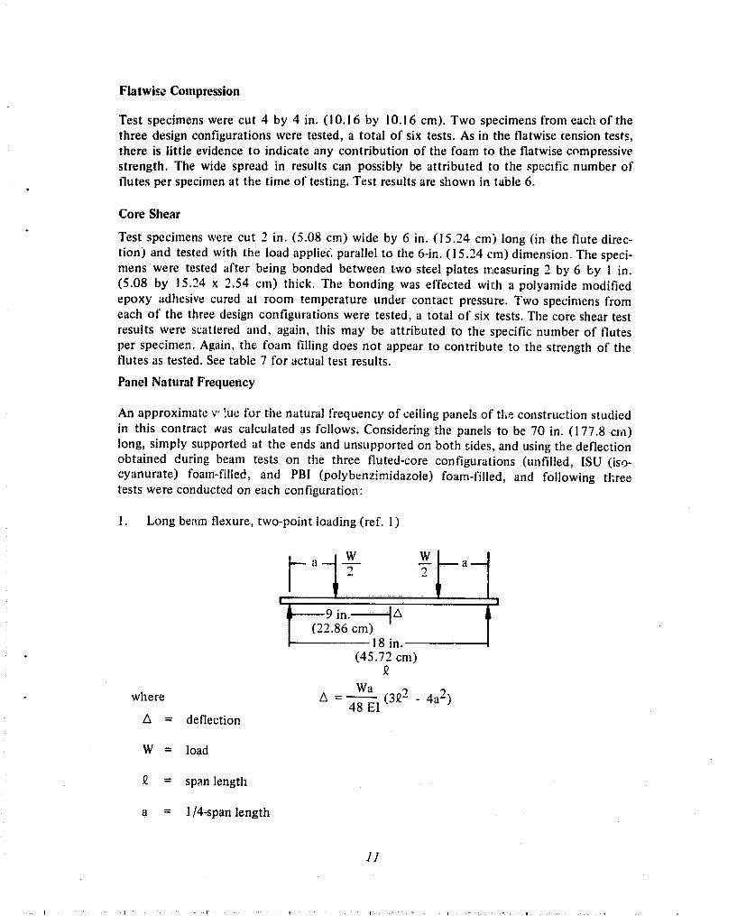
Panel Natural Frequency
An approximate v lue for the natural frequency of ceiling panels of tlie co~istrt~ction studied in this contract #as calculated as fcllows. Considering the panels to be 70 in. (177.8 crn) long, simply supported at the ends and unsupported on both sides, and using the deflection obtained during beam tests on the three fluted-core configurations (unfilled, ISU (iso- cyanurate) foarn-filled, and PBI (polybriizimidazole) foam-filled, and following t h e e tests were conducted on each configuration:
1. Long benm flexure, two-point loading (ref. 1)
where
A = deflection
W = load
1 8 in.- (45.72 cm)
0
11 = span length
a = 1/4span length

2. Short beam flexure, single-point loadilrg (rcf. I ) W
f 6 in. -+ (1 5.24 cln)
a A I T- 12 in.-I
(30.48 cm) Q
W P ~ A = - 48 EI
3. Short beam core shear, single-point loading Q
t y t ; <
8 in. (20.32 cm)
w t 3 P A =- 4 8 EI
Solution: From the detlections (A) measured during the beam tests, the slope of the deflec- tion curves (W/A) can be determined.
Equations (1) and (2) can be solved for EI as a function of W/A and d s t dimensions,
The natural frequency of a beam (or panel) unsupported on the edges (ref. 2) can then be determined by Rayleigh's Method using
where
f = natural frequency
P = distance between the supported ends
w = the uniform density of the panel (beam) in weight per unit length
The results are shown in table 8 .

All calculations were based on properties for the 4-in. (10.16 cm) wide samples; however, since E is unaffected by specimen widtl~ and both I and w vary directly as the width, the results would be rbe same for any panel widt~i that might reasonably be used in an aircraft ceiling. It is therefore concluded that the three panels studied would have a natural fre- quency of approximately 3 5 t o 4 0 cps in 70-in. (177.8 cm) endsupported lengths. This is well above the minimum requirements of 15 cps to prevent visible panel vibrations. The calculated natural frequency of the tested 747 baseline interior sidewall F-nel is 38 cps.
In actual use, such panels are normally stiffened by edge treatment and stiffeners on the back side to eliminate unacceptable sag. Then the parts would have higher natural frequency values.
The calculated El (flexural rigidity) of the samples, while not in exact agreement, establishes the magnitude as being correct for each configuration. In calculating the approximate natural frequency for each configuration, the El established for the long beam flexure test is considered to be most nearly representative, since in the short beam tests the vaiue tends to be lowered by more core 'eformation and bond loading than would occur in limited deflections of a longel' panel (beam).
Therefore, using equation (31,
the results are as shown in table 9.

5.0 SUMMARY AND CONCLUSIONS
Initially, n preliminary design study was conducted to define requirements and to establish baseline characteristics for a typical jet transport fuselage wall. The characteristic!: of the current Model 747 were selected as the baseline standard for comparison.
The NASA-defined improved panels were designed and fabricated to meet baseline require- ments of the current 747 interior panels, plus structural requirements set forth in the sub- ject contract. The NASAdefined lluted-core panels, with and without the foam-filled cores, wzre found to be significantly heavier than the current 747 sidewall and ceiling interior panels. Tlie panel weights, as tested, were:
Weight - Panel Identification - -
747 Baseline interior wall panel 0.250 (1.22)
NASA-unfilled fluted core 0.405 (1.98)
NASA-PBI foam-filled core 0.509 (2.49)
NASA-ISU foam-filled core 0.474 (2.3 1 )
Thermal and acoustical insulation is currently achieved by an airspace plus fiberglass insula- tion between the fuselage skin and the interior panel. The heavier foam-filled fluted-core panels do not offer any improvement in this area, since the acoustical insulation is primarily achieved via the fiberglass insulation.
Flame tests and mechaincal property tests were conducted on these three NASA-defined improved interior panels and compared to the 747 baseline interior panels.
5.1 FLAME TESTS
The flame tests conducted by NASA-Ames showed no bum-through of any of the panels tested, but the state-of-the-art (747) panel was very close and had no structural integrity remaining. The woven fluted-core panels were quite stiff and retained structural integrity. No tests were conducted to determine actual panel strength after flame testing. See pictures si tested panels in figures 9 through I I .
In both the backface temperature and cabin air temperature, the best performing material was the PB1 foam-filled fluted-core panel.

5.2 MECHANICAL PROPERTY TESTS
The face compressive stresses of the NASA-dcfined woven fluted-core panel with PBI com- pares favorably with the design allowahles for the baseline 747 interior wall panel. Since there was no core failure in the NASAdefined panels as tested for long beam flexure, short beam flexure, and sliort beam shear, the results are co~npilrable for each of tlie three NASA- defined panels.
In flatwise tension and compression, tlie NASA-defined fluted-core panels weighed about twice: as much as tlie 747 baseline panel; therefore, on a strength-to-weight basis, tlie preser,t 747 baseline panel is twice as strong.
5.3 COST ANALYSIS
The cost of the developnlent panels tested in this prograni could not be equated to cost of the current 747 production iriterior sidewall panels.
Boeing Comniercial Airplane Company P.O. Box 3707
Seattle, Washington 98 124 April 1976

'$Airplane
0.25-in. 10.635 cm).2024-~351 Aluminum skin
4 Lavers-thermal acoustical
114 in. 10.635 cm) thick, 118 in. 10.318 cm) cell 3.0 lb/ft3 10.048~1cm3) Nomex panel (sidewall)- iberglar-Tedlar faces
Section I3.B
114 in. (0.635 cm) Thick. 1 5 4 . . in (0 . 635 cm) cell, 1.5 lb/ft3 (0.024GIcm ) Nomex panel (ceiling)-Tedlar faced fiberglass-epoxy skins
Section A-A Figure 1.-747 Section

1/4.in. (0.635 cm) thick fluted core with flutes spaced 314 in. (1.905 cm\ apart. ISU or PBI foam in flutes with a decorative fly screen surface on one side.
Figure .?.-Test Panel Cross Section


Empty woven structure 0 Cabin temperature with 0.040 in. (0.1016 cml aluminum skin I in. I m lnside wall temperature 12.54 cml depth Light transmission (---)
Cabin temperature Empty woven structure without aluminum skin 0 lnside wall temperature
4 Light transmission I--)
Time, minutes

Starting flu* 10.5 Btulft2.sec
Cabin temperature Inside panel temperature
0 Empty woven structure (3 Design No. 1
Ending flux 0 State.ot-the-art Boeing panel Baseline A 12.0 Btu/ftZ.sec ISU in woven structure Design No. 2
Low temperature cure PBI in woven structure Design No. 3
4 Advanced Booing honeycomb F Baseline B
No aluminum skin
- - - -
L' BOO 1427)
Y 0
g- ). TIC Losta
I- \ m. . - m - -*
Time, minutes a ~ o s t TIC decomp. of Tedlar inner liner.
Adv. Boeing
SA MT
ISU PBI
Figure 5.-Flame Test-Jaseline and Test Panels

Design No. 3 0 Open woven structure-high temp cure
Baseline A A '?ate.of-chpart Boeing panel
Design No. 2 0 Woven structure/lSU foam-low temp cure resin
Design No. 1 Woven structure/PBI toam-low temp cure resin
Baseline 8 Boeing advanced panel
Time, minutes
Figure 6.-Flame Test-Cabin Temperature Rise Verslrs Time
21

Effect of bismalimide matrix cure temperature on cabin air temperature
Design No. 2 { 0 Low temp cure. with ISU High temp cure with ISU
A Low temp cure with PBI Derig:! No. 1 { .
A High temp cure with PBI
Design No. 3 { 0 Open structure-low ?emp cure Open sturcute-high temp cure
Time, minutes
Figure 7.-Cabin Temperature Rise-High and Low Temperature Cured Resin Systems

Design No. 3 0 Open woven structure
Design No. 2 O Woven structure1lSU fcam
Design No. 1 X Woven structurelPBl foam
Baseline A A State-of+t;ieart Boeing panel
Baseline B Boeing advnnced panel
Time, minutes
Figure 8.-Cabin Smoke-Light Transmission Versus Time
23

. i I"<,,l*.
IJnf~lled Fluted Core Uutr l r l ,~
Inridi! 8oeing State of the Art
Fig11re 9. -Picri/res- Flariip Tcsr Kes111ts

Inside Uurskdr ISU Foam Filled
@mT;am?.r? .!y.v..--~:,.: , . ~ - v .--W?qm :-<- , ,. .,
Insirlc PBI Foam Filled
Figure 70.-Pictures-Flar~ie Test Res i~ l rs

2 . . . . . . . . . 11121<11. Ourilri,,
PO Filled High Temp Cure Flame Tested 'zr Informatoon Only
InscI': Boeing Advanced Concept
Fjgure 7 I . -Pictc~res- Flanie Test Re.ui:is
1
-'O '

I - Decorative Tedlar sheet
Skin, epoxy, type 181 fiberglass
Table 7.-Boeing 747 Baseline
- Bond ply. epoxy, type 120 fiberglass
flmfl Nomex i>oneycomb core. 118 cell, 114 in. thick
a~ested with decorative face skin in compst;ssion
Allowables psi (kglcm21 Tests
Results 2 psi (kglcm 1
Interior Sidewall Fanel
13 400 (9421
13 400 1942)
100 ( 7.01
92 ( 6.51
65 14.61
Long beam flexurea
Short beam flexurea
Flatwise tension
Flatwise compression
Core shear - Typical Sidewall Panel Construction
r
16057 (11291
16001 (11251

Table 2.-Long Beam Flexure
78-in. Span, Two.Point, f/4-Span Loading I 1 I I I
1 Design No. 2, ISU Foam-Filled Flutes 1
Specimen number
Design No. 3, No Foam in Flutes I I I
a ~ n i t load i s listed in pounds (kilograms) at failure.
Desion No. 1. PBI Foam-Filled Flutes
Unit load? Ib (kg1
b ~ / ~ is the slope of the tangent drawn to the initial portion of the load deflection (stress.strain) curve in poundsfinch (kilogramrfcentirneter~.
P/Y? Iblin. (kglcm)
Face comp-essive stress. psi (kglcm2)

Table 3. -Short Beam Flexure
I Design No. 2, ISU Foam.Filled Flutes I
12-in. Span, SinglePoin f Loading
Design No. 3, No Foam in Flutes
a h i t load is listed in pounds (kilograms) at failure.
Face compressive stress, psi (kg/cm2)
Specimen number
b ~ / ~ is the slope of the tangent drawn to the initial portion of the load deflection (stresr-strain) curve in poundslinch (kilogramilcentimeter).
Unit load? Ib (kg)
Design No. 1, PBI Foam-Filied Flutes
Iblin. (kglcm)
1 2 3 4 5 6 7 8
Avg
300 153.6) 284 (50.7) 292 152.1 ) 288 (51.4) 300 (53.6) 304 (54.3) 300 (53.6) 300 (53.6)
296 (52.9)
115.0 (52.16) 117.5 (53.30) 95.5 (43.32)
101.5 (46.04) 112.5 (51.03) 109.5 (49.67) 118.0 (53.52) 110.0 (49.90)
109.94 (49.87)
14 213.6 ( 999.2) 14 522.6 (1,020.9) 11 803.5 ( 829.8) 12 545.1 ( 881.9) 13 904.6 ( 977.5) 13 533.8 ( 951.4) 14 584.4 (1 025.3) 13 595.6 ( 955.8)
13 587.9 955.2)

Table 4.-Short Beam (Core) Shear
8.h. Span, Singir.Poinr Loading
a ~ n i t load i s listed in pounds (kilograms) at failure.
b p / ~ is the slope of the tangent drawn to the initial portion of the load deflection (stress-strain) curve in pounds/inch (kilograms/centimeter).
Specimen number
Unit load? Ib (kg)
P/Y .b Iblin. (kglcm)
Face compressive stress, psi (kglcm2)
Design No. 1, PBI Foam-Filled Flutes
1 2 3 4
Avg
146.5 166.45) 142.0 (64.41 11 7.0 (53.071 139.0 (63.05)
136.12 161.74)
870 (155.4) 860 1153.6) 874 (156.1 1 920 (164.3)
881 (157.3)
12 071.3 (848.6) 11 700.5 (822.5) 9,640.5 (677.7)
11 453.3 1805.2)
11 216.4 (788.5)
Design No. 2, ISU Foam-Filled Flutes
1 2 3 4
Avg
125.0 (56.70) 11 2.5 (51.031 115.0 (52.16) 113.5 151.48)
116.50 (52.84)
Design No. 3. No Foam in Flutes
693 (123.7) 680 (121.4) 680 (121.4) 700 (125.0)
688 (122.0)
1 2 3 4
Avg
10 299.7 (724.1) 9 269.7 (651.7) 9 475.7 lE66.1) 9 352.1 (657.5)
9 599.3 (674.81
105.5 (47.85) 110.5 (50.12) 120.5 (54 661 119.0 153.98)
11 3.87 151.66)
726 (129.61 126 (129.6) 733 (130.9) 746 (133.2)
733 (130.9)
8,693.0 (61 1.1) 9 105.0 1640.1) 9 928.9 (698.0) 9 805.3 (689.3)
9 383.0 1653.6)

Table 5.-Flatwise Tension
Table 6. - Flatwise Compression
Specimen number
- Unit load at failure
Specimen number
Ib (kg)
Design No. 1, PBI Foam-Filled Flutes
psi (kg$cm2)
1 2
Unit load at failure
Ib ( kg )
Design No. 1. PBI Foani-Filled Flutes
265 11 20.20) 330 1149.68)
psi (ky/cm2)
66.25 (4.66) 82.50 (5.80)
Design No. 2, ISU Foam-Filled Flutes
11 9.38 18.39) 1
- 1 2
1 910 (866.36) 2
233 1105.69) 430 1195.04)
1 620 (734.82) 101.25 (7.12)
58.25 (4.09) 107.50 (7.56)
Design No. 3. No Faam in Flutes
1 2
Design No. 2. ISU Foam-Filled Flutes I
385 (174.63) 380 (1 72.36)
141.88 (9.971 135.00 (9.49)
1 2
96.25 16.77) 95.00 (6.68)
2 270 (1 029.65) 2 160 1 979.75)
Design No. 3. No Foam in Flutes - 1 2
1 160 1 526.16) 2 660 ( 1 206.55)
71.88 (5.05) 141.25 19.93)

Table 7.-Core Shear
Specimen number
a ~ o r 4-in.-wide test sample (beam) from test data
Table 9.-Panel Natural Frequency
Table 8.-Panel Flexural Rigidity
U ! at failure
a ~ o r 4-in.-wide sample
32
Ib (kg)
Design No. 1. PBI Foam-Filled Flutes
Configuration
Unfilled
ISU filled
PBI filled
Configuration
Unfilled
ISU filled
PBI filled
psi (kglcm2)
Test
Long beam flexure
Short beam flexure
Short beam core shear
Long beam flexure
Short beam flexure
Short beam core shear
Long beam flexure
Short beam flexure
Short beam core shear
(WlA I avg." Iblin. (kglcm)
116 ( 20.7)
245 ( 43.7)
733 (130.9)
123 ( 22.0)
235 ( 42.0)
688 (1 22.9)
146 ( 26.1)
296 ( 52.9)
881 (157.3)
195.00 113.71) 102.92 ( 7.24)
I
1blin.2 (kglcrnz)
9 700 (681.9)
8 800 (618.6)
7 800 (548.3)
10 300 (724.1)
8 500 (597.6)
7 300 (513.2)
12 200 (857.7)
10 700 (752.2)
9 400 (660.8)
El. ~ b / i n . ~ (kgIcm2)
9 700 (681.9)
10 300 (724.1)
12 200 (857.7)
1 2
!? 3:O (1 061.40) 1 235 ( 560.18)
Design No. 2. ISU Foam-Filled Flutes
w? Iblin. (kglcm)
0.01 12 (0.0020)
0.0131 (0.0023)
0.0141 (0.0025)
1 2
in. (cm)
70 (178)
70 (178)
70 (1781 36.8
1 380 (625.951 1 580 (716.67)
1 15.00 (8.08) 131.66 (9.26)
Design No. 3. No Foam in Flutes
1 2
1 340 (607.81) 1 535 (696.26)
11 1.66 (7.85) 127.92 (8.99)

REFERENCES
I . p.~Pov, E.P.: Irtrroductio~t lo illeclro~~ics of Solids. Prentice Hall, 1968, p. 564
2 . T l ~ o ~ n s o n , W. T.: ~\Iccl~u~ticul Vihmliotrs, S~cortd Edilior~. 1956, p. 163.