ntrs.nasa.gov · nasa cr175084 r i1rd86-116 nasa-cr-175084 19860016897 ni\si\ in1erim report orbit...
TRANSCRIPT

NASA CR175084 R I1RD86-116
NASA-CR-175084 19860016897
NI\SI\ IN1ERIM REPORT
ORBIT TRANSFER ROCKET ENGINE TECHNOLOGY PROGRAM
ADVANCED ENGINE STUDY TASK 0.1/0.3
Prepared By: A. Martinez, C. Erickson, B. Hines ROCKWELL INTERNATIONAL CORPORATION
Rocketdyne Division
Prepared For:
NATIONAL AERONAUTICS AND SPACE ADMINISTRATION
January 1986
NASA-Lewis Research Center
Contract NAS3-23113
L. P. Cooper, Project Manager
LANGLEY RF.SE~Rl;;-t l;t:NTER liBRARY, N,I'-\SA
I-!A:.~PTOrJ, VIRGINIA
ROCKETDYNE DIVISION OF ROCKWELL INTERNATIONAL CORPORATION 6633 Canoga Avenue; Canoga Park, CA 91303
111111111111111111111111111111111111111111111 NF01244
https://ntrs.nasa.gov/search.jsp?R=19860016897 2018-07-28T16:05:30+00:00Z


1. Report No. 2. Government Accession No. 3. Recipient's Catalog No. NASA
.4. Title and Subtitle 5. Report Date
ORBIT TRANSEE~ ROCKET ENGINE TECHNOLOGY ... JANUARY 1986 PROGRAM - INTERIM REPORT. ADVANCED ENGINE STUDY 6. Performing Orllllnization Code
7. Author(s" 8. Performing Organization Report No. A. MARTINEZ. C. ERICKSON. B. HINES RI/RD86-116
10. Work Unit No. 9. Parformlng Organization Name and Address RTPO 506-42-21. TASK YOS2582
ROCKETDYNE DIVISION. ROCKWELL INTERNATIONAL 6633 Canoga Avenue 11. Contl'lCt or GllInt No.
Canoga Park. California 91304 NAS3-23773
13. Type of Report and Period Covered
12. Sponsoring Agency Name and Address Interim Report NASA-Lewis Research Center. Communications and Propulsion Section. 21000 Brookpark Road 14. Sponsoring Agency Code
MS 500-306. Cleveland. Ohio 44135 15. Supplementary Notes
Project Manager. L. P. Cooper. NASA-Lewis Research Center, Cleveland, Ohio MSFC Coordinator, S. McIntyre, NASA-Marshall Space Flight Center, Huntsvi 11 e, Alabama
16. Abstract
In this study concepts for space maintainability of OTV engines were examined. The advanced technology efforts were conducted under the Advanced Engine Study Task of the Orbit Transfer Rocket Engine Technology Program. An engine design was developed which was driven by space maintenance requirements and by a Failure Modes and Effects (FME) analysis. Modularity within the engine was shown to offer cost benefits and improved space maintenance capabilities. Space-operable disconnects were conceptualized for both engine change-out and for module replacement. Through FME mitigation the modules were conceptualized to contain the least reliable and most often replaced engine components. A preliminary space maintenance plan was developed around a Controls and Condition Monitoring system using advanced sensors, controls, and condition monitoring concepts. A complete engine layout was prepared satisfying current vehicle requirements and utilizing projected component advanced technologies. A technology plan for developing the required technology was assembled.
17. Key Words (Su~ted by Author/sll Hydrogen xygen Engine
18. Distribution Statement
Hydrogen/Oxygen Technology High Pressure Pumps/Combustion High Area Ratio Nozzles Expander Cycle Engine
19. Security Cassif. lof this report) 20. Security Classif. lof this page) 21. No. of Pages 22. Price'
Unclassified Unclassified
• For sale by the National Technical Information Service. Springfield. Virginia 22151
NASA·C.168 (Rev. 6-71) i

CONTENTS
INTI{ODUCTION ............................................................ 1 OBJE.C rIVES ........................................................... 1 APPI{OACH. . . . . . . . . . . . . . . . . . . . . . . . . . . . . . . . . . . . . . . . . . . . . . . . . . . . . . . . . . . .. 1
SUMMARY OF ACCOMPLISHMENTS ...............................•.............. 4 TECHNICAL DISCUSSION .................................................... 8
INl ~ODUCTION ..........................•.............................. 8 ID~N'IFICATION OF VEHICLE-DERIVED-REQUIREMENTS ................•...... 10 BASELINE ENGINE DEFINITION ...............•..........•..........•..... 15
ADVANCED COMPONENT TECHNOLOGIES ....••........••.................. 15 ENGINE PERFORMANCE OPTIMIZATION .................................. 11 ENGlNE THRUST STUDy .............................................. 24 CON T I{OL SYSTEM ASSESSMENT ........................................ 24 THHOlfLING AND STABILITY.~ ....................................... 35
FAILURE MODE EFFECTS AND RELIABILITY ANALYSES REVIEW ................. 39 FMl:A AND RELIABILITY ANALySES ......•..........•.................. 39 FME. MITIGATION AND RELIABILITY IHPROVEMENT ....................... 43
APPI{OACH ..............................•...................... 43 COMPONENT DESIGN EVLUATION ................................... 45 ENGlNE AND CYCLE DESIGN EVALUATION ........................... 48 THI{UST AND MR CONTROL DURING TRANSIENT ....................... 54 REDUNDANCY ................................................... 59 ICHM EVOLUTION ............................................... 64 SERV ICING ...•..•..••.•.•....•••..••........•.•..•.•.•••....•. 71
i i
R I1RD86-116
CONTENTS (continued)
MAINTAINABILITY STUDIES & PLAN .............................•.......... 72 REQUI REMENTS ••.• ~ • . • • • . . • • . • • • • . • . • . • • . • . • . . • • • • . • . . • • . • • • . • • • • . • .• 83
ICHH SYSTEM REVIEW ..•.•.•..••.•.••.•.•.•..•.•..•.••••••..•..•.•.••.•.. 91
VEHICLE/SYSTEM INTEGRATION ....................•....................... 92 COUPLING OPERATION ................................................. 108 PERFORMANCE DURING ENGINE OPERATION ...................•..•......... 110 FABRICATION/DEVELOPMENT/MAINTENANCE ................................ 112
ENGINE AND COMPONENT DESIGN ........................................... 118 ADVANCED ENGINE CONCEPTS .............................................. 132 ENGINE DESIGN UPDATE .................................................. 140 TECHNOLOGY PLANS ...................................................... 145
TASK NO.1 TURBINE SHUTOFF VALVE (TSV) ............................. 146 TASK NO.2 CONSOLIDATED TSV AND TBV ................................ 148 TASK NO.3 CONSOLIDATED MOV AND GOV ................................ 150 TASK NO.4 ELECTRIC ACTUATED CARTRIDGE VALVES ...................... 152 TASK NO.5 MODULAR IGNITER ......................................... 154 TASK NO.6 COMPOSITE MATERIALS ..................................... 156 TASK NO.7 NOZZLE RETRACTION DEVICES ............................... 158 TASK NO.8 NOZZLE FLUID INTERCONNECTS .............................. 160 TASK NO.9 NOZZLE SEGMENT INTERFACE SEALS .......................... 162 TASK NO. 10 SPACE OPERABLE FLUID DISCONNECTS ....................... 164
iii
RIIRD86-116

TABLES
1 ADVANCED ENGINE STUDIES ...................................... 2 2 OTV ROCKET ENGINE TECHNOLOGY TASKS, NAS3-23773 ............... 3 3 PHASll - FMEA-MAINTENANCE DRIVEN DESIGN ACCOMPLISHMENTS ...... 6 4 ENGINE DESIGN DRIVEN MISSIONS ................................ 11 5 ENGINl REQUIREMENTS, 1990'S OTV (PRIORITIZED) ................ 12 6 ENGINE CHARACTERISTICS - 1990' S OTV .......................... 14 7 RESULTS SUMMARY OF ENGINE OPTIMIZED RUNS FOR ADVANCED ..•...•. 19
TECHNOLOGY ENGINE AT 7500 LB THRUST B TURBOMACHINERY TIP SPEED AND STRESS LIMITS ................... 20 9 BASlLINE ENGINE DESCRIPTION .................................. 25
10 ENGINE CONTROLS SYSTEM CONCEPTS DEFINITION ................... 26 11 EXPANDER CYCLE PERFORMANCE ................................... 29 12 ACTUATOR REQUIREMENTS ........................................ 30 13 EXPANDER CYCLE ENGINE START AND SHUTDOWN REQUIREMENTS ........ 32 14 VALVE SUMMARy ................................................ 35 15 OTV 7.5K ENGINE OFF-DESIGN SUMMARy ........•....•............. 36 16 7.5K LBENGINE BALANCE SUMMARY AT OFF-DESIGN .•.•.••••••••.•.•. 3B
THRUSTS AND MIXTURE RATIOS 17 DIV ENGINE CRITICALITY SUMMARy ............................... 42 18 FMEA MITIGATION AND RELIABILITY IMPROVEMENT .................. 44 19 FAILURE MITIGATION THROUGH ENGINE AND ICHM DESIGN ............ 46 20 FAILURE MODE MITIGATION AND RELIABILITY IMPROVEMENT .......... 47
VALVE ACTUATOR DESIGN 21 IMPROVING TURBOMACHINERY RELIABILITy ......................... 49 22 OFF-DESIGN LIFETIME IMPACTS ON OTV ENGINES ................... 52
iv
R I1RD86-116

TABLES (continued)
23 COMPARISON OF 7.5K AND DERATED 15K ENGINES ................... 53 24 MODULAR ENGINE DESIGN-FM BREAKDOWNS .............•............ 55 25 7.5K ENGINE STARTS AND SHUTDOWN TIME CAPABILITIES ............ 5B 26 OTV lNGINE RELIABILITY DATA .................................. 63 27 FUNCTION REDUNDANCY-ENGINE AND TURBOMACHINERY ................ 65
(MEAN TIME TO FAILURE AND RELIABILITY) 28 ADVANCED ICHM SENSORS .......................................• 69 29 COSI COMPARISON OF R&R MAINTENANCE OPTIONS ................... 79 30 GROUND VS. SPACE R&R MAINTENANCE TIME AND COST ............... 82 31 CONI~OL AND HEALTH MONITORING INSTRUMENTATION ................ 84 32 lNGINE COMPONENTS LIFE. 15K LB NEAR-TERM ENGINE .............. 87 33 ADVANCED INTERFACES ENABLE SPACE MAINTENANCE ................. 93 34 MODULAR ENGINE INTERFACE LOCATIONS & ENVIRONMENTS ............ 107 35 ADVANCED INTERFACE COUPLING SELECTION ........................ 109 36 INTERFACE COUPLING EVALUATION -1 ............................. 114 31 INllRFACE COUPLING EVALUATION -2 ............................. 115 38 INTERFACE COUPLING EVALUATION -3 ............................. 116 39 ENGINl MODULARITY OPTIONS .................................... 125 40 ADVANCED OTV ENGINE WEIGHTS .................................. 128 41 WEIGHT EFFECTS OF SPACE MAINTAINABILITY INTERFACES ........... 131 42 INNOVATIVE CONCEPTS LIST ..................................... 133 43 IGNlIll~ COMPARISON ........................................... 144
v
RIIRD86-116

FIGURES
1 ADVANCED ENGINE STUDY SCHEDULE ............................... 7 2 PHAE I STUDY LOGIC DIAGRAM .................................. ; 9 3 BASELINE OTV ENGINE .......................................... 16 4 7. 5K ENGINE COMPONENT TECHNOLOGIES ........................... 18 5 SERIES TURBINE BASELINE OTV ENGINE SCHEMATIC - .............. 28
MAIN PROPELLANT CONTROL VALVES 6 DUAL-DUAL REDUNDANT CROSS-STRAPPED SySTEMS ................... 33 7 PR~UICTED FUEL PUMP PERFORMANCE FOR 7500 LB ENGINE ........... 37 8 FAILURE MODE EFFECTS AND RELIABILITY ANALYSIS REVIEW ......... 40
AND APPLICATION
9 O~~-DESIGN LIFETIME TRENDS THRUST CHAMBER .................... 50 10 MODULAR ENGINE, TOP VIEW .............................•....... 56 11 OlV 7.5K ENGINE FLOW SCHEMATIC WITH TURBINE .................. 60
SHUTOFF VALVE 12 RlUUNOANT TURBOPUMP FUNCTIONS ................................ 62 13 REDUNDANCY, MISSION COST IMPACT .............................. 66 14 MOUULIII~ OTV ENGINE WITH ADVANCED INSTRUMENTATION ............. 70
SCHEMATIC 15 01V lNGINE FUEL TURBOPUMP .................................... 75
REMOVAL/INSTALLATION/CHECKOUT TIMELINE 16 0 I 'J ENGINE FUEL MODULE. ...................................... 76
REMOVAL/INSTALLATION/CHECKOUT TIMELINE 17 OTV ENGINE ASSEMBLy .......................................... 77
REMOVAL/INSTALLATION/CHECKOUT TIMELINE
vi
RIIRD86-116

FIGURES (continued)
18 OTV ENGINE FUEL TURBOPUMP .................................... 80 REMOVAL/INSTALLATION/CHECKOUT TIMELINE (ON GROUND)
19 MAINTENANCE PLAN OUTLINE ..................................... 85 20 ICHM FUNCTION ALLOCATION AND LOGIC DIAGRAM ................... 90 21 SELF-RETAINED, REDUNDANT SEALING FACE SEAL CONCEPT ........... 95 22 CAPllVE-BOLT DISCONNECT JOINT ........•....................... 96 23 CARRIAGE/HOOK COUPLING CONCEPT ................•............•. 98 24 SPRING-COLLAR INTERFACE COUPLING CONCEPT ................•.... 99 25 SPRING-COLLAR COUPLING INSTALLATION TOOL ..................... 101 26 SEGMENTED-THREAT COUPLING CONCEPT ............................ 102 21 CONOSEAL V-BAND COUPLING ..................................... 104 28 GAMAH EDGE SEAL .............................................. 104 29 DYNATUBE COUPLING ............................................ 106 30 PARK~R LO-TORQUE COUPLING .................................... 106 31 OTV 4-STAGE HPFTP ............................................ 119 32 HK 49-0 HPOTP ................................................ 120
33 THRUST CHAMBER ASSEMBLY ...................................... 122 34 FLIGHTWEIGHT ELECTRIC ACTUATED VALVE ......................... 123 35 MODULAR OTV ENGINE-SCHEMATIC .................•............... 124 36 1.5K ADVANCED SPACE-BASED OTV ENGINE ARRANGEMENT -AP84 ....... 121 31 1.5K ADVANCED SPACE-BASED OTV ENGINE ARRANGEMENT -1R03 ....... 141 38 MODULAR IGNITER CONCEPT ...................................... 143
vii
R IIRD86-116

FOREWORD
The work reported herein was conducted by the Advanced Programs and Engineering personnel of Rocketdyne, a Division of Rockwell International Corporation, under Contract NAS3-23113 from June 1984 to January 1986. Dr. L. P. Cooper, Lewis Research Center, was the NASA Project Manager. Mr. A. T. Zachary was the Rocketdyne Program Manager, and Mr. A. Martinez, as Study Manager was responsible for the technical direction of the program.
Important contributions to the conduct of the program, and to the preparation of the material, were made by the following Rocketdyne personnel:
Engine System Analysis Engine System Design Failure Modes and Effects Analysis Consolidated Valve Design
viii
RI/RDB6-l16
D. Nguyen, C. Erickson B. Hines T. Hull G. Tellier

INTRODUCTION
The Advanced Engine Study (Task 0.1) has been outlined as a four year effort in which the engine design will be iterated four times to allow resolution of vehicle/engine integration issues as well as advanced engine performance, operation and maintenance technology issues. When completed the conceptual engine system design description will include all the engine subsystems. Design iteration of the ICHM subsystem will be performed in Task E.2 -Integrated Control and Health Monitoring System. Each successive iteration will provide as output an updated engine system design, and the advanced technology and plans required for expeditious development of the spacebaseable and maintainable engine. The complete four year effort is described in Task Work Plan Document RI/RDB4-122.
OBJECTIVES
Objectives, and status of the Advanced Engine Study are indicated in Table 1. The overall objective is to develop a space-baseable engine design and to define and update its advanced technology and technology development plans.
APPROACH
The approach to performance of the objectives is to develop the engine design and technology plan in four study phases as outlined in Table 1.
Each phase will be driven respectively by the timing and results of four main occurrences: (1) the completion of advanced engine FMEA (Failure Mode and Effects Analysis) and maintenance studies; (2) the completion of Orbit Transfer Vehicle (OTV) definition and Aeroassist OTV studies; (3) the completion of near-term advanced technology evaluation studies of NAS3-23113 Contract Tasks B.1, C.1, B.2, and F.2; and (4) the completion of longerrange advanced technology studies of NAS3-23773 contract Tasks E.1, E.2, B.3, and A.B (Table 2).
1 RI/RDB6-116

:;0 ...... ....... :;0 o N ex> C"I I ..... .....
C"I
TABLE 1.
ADVANCED ENGINE STUDIES
OBJECTIVES:
• PROVIDE A SPACE BASABLE/MAINTAINABLE ENGINE DESIGN • IDENTIFY ADVANCED TECHNOLOGY REQUIRED • PREPARE TECHNOLOGY AND ENGINE DEVELOPMENT PLANS • UPDATE ENGINE DESIGN AND TECHNOLOGY THROUGH 1990
APPROACH:
• DEVELOP ENGINE DESIGN IN FOUR PHASES
• PHASE I • PHASE II • PHASE III • PHASE IV
STATUS:
FMEA - MAINTENANCE DRIVEN DESIGN THRUST LEVEL ENGINE DESIGN UPDATE PERFORMANCE, LIFE, OPERATIONS DESIGN UPDATE FINAL ICHM/MAINTENANCE/FMEA UPDATE
• PHASE I - COMPLETED • PHASE II - FUNDING PENDING

TABLE 2. OTV ROCKET ENGINE TECHNOLOGY TASKS, NAS3-23773
Task B.l - Two-Stage Partial Admission Turbine Task C.l - Enhanced Heat Load Thrust Chamber Task E.l/E.2 - Integrated Control and Health Monitoring System Task F.2 Task B.2 Task B.3 Task A.a
- Integrated Components Evaluator - High Velocity Diffusing Crossover - Soft-Wear Ring Seals - Hydrogen Regenerator
3 R I1RDB6-116

SUMMARY OF ACCOMPLISHMENTS
After an in-depth review of vehicle derived requirements provided by the four vehicle contractors, a 7500 lb thrust baseline engine was selected. Engine operation studies were conducted to define and optimize engine design parameters for this baseline engine. This was followed by a review of the FEMA and reliability analyses which were conducted under the ICHM Task E.l. In this review, the impact of the FMEA on engine design was assessed and methods for FME mitigation and reliability improvements through component design evolution, engine and cycle design evolution, redundancy schemes, and ICHM evolution were generated. Concurrently, an initial space-based maintenance philosophy was established and requirements for its implementation were determined. This maintenance philosophy centers on the benefits of a modular engine concept and the use of advanced sensors for health monitoring. In this approach, engine servicing will be done on an as-needed basis determined by the health monitoring systems as opposed to a more frequent scheduled routine. In addition, health monitoring would obviate costly routine inspections required to assess components status. When servicing is required, the modular engine design permits quick and easy removal and replacement of component groups. Space-based servicing such as this requires advanced fluid disconnects easily operable by an EVA astronaut or robotic manipulator. Several preliminary design concepts for space operable fluid disconnects were generated during this study. These concepts were evaluated and ranked based on coupling operatin, performance, fabrication, development, and maintenance.
As part of the advanced concept evolution, a comprehensive list of innovative ideas was identified and evaluated by the respective components specialists. Many of these concepts were offshoots of the FMEA review and maintainability studies and thus are integral parts of the space-based maintenance philosophy. Technology plans were generated for several of the concepts which were deemed as worthy of further investigation with fruition expected within the time frames of interest.
4 RI/R086-ll6

Efforts of this study culminated in the generation of an updated maintenance driven engine design. Salient features of this design include space operable vehicle interface couplings, advanced sensors for health monitoring, and a dual igniter module. Disconnects permitting modular maintenance were not included since the current preference of the vehicle contractor for servicing is engine only replacement. However, the packaging and line arrangement is configured such that modular servicing could be realized with the simple addition of couplings.
A summary of the Phase I - FMEA-Maintenance driven design accomplishments is presented in Table 3. In addition, a program schedule highlighting the milestones completed is shown in more detail in Figure 1.
Additional effort will be required in Phase 2 for evaluation of several of the innovative concepts which were not addressed in this study. Development of the maintenance plan will be an on-going effort and is expected to progress in parallel with the evolution of the space-based engine in the subsequent phases of the study.
5 RI/RDB6-116

TABLE 3. PHASE I - FMEA-MAINTENANCE DRIVEN DESIGN ACCOMPLISHMENTS
• SELECTED 7500 LB BASELINE ENGINE
• DETERMINED IMPACT OF FMEA ON ENGINE DESIGN
• ESTABLISHED INITIAL SPACE BASED MAINTENANCE PHILOSOPHY AND REQUIREMENTS
• DETERMINED IMPACT OF FMEA/MAINTENANCE ON ENGINE PACKAGING
• IDENTIFIED AND EVALUATED INNOVATIVE CONCEPTS
• GEN~RATED TECHNOLOGY PLANS REQUIRED FOR ADVANCED ENGINE EVOLUTION
• GENERATED PRELIMINARY DESIGN FOR SPACE OPERABLE FLUID DISCONNECTS
• GENERATED UPDATED MAINTENANCE DRIVEN ENGINE DESIGN INCORPORATING INNOVATIVE CONCEPTS
6 RI/RD86-116

;::0 ......
'" ;::0 o CO ....... C'l I ...... ......
C'l
ADVANCED ENGINE STUDY SCHEDULE
SUBTASK
SUBTASK I - ANALYSIS AND PRE LIM. DESIGN
REQUIREMENTS AND GOALS
POWER CYCLE OPTIMIZATION
PERFORMANCE TRADES
ENGINE OPERATION STUDIES
PRELIMINARY DESIGN (COMP. AND SYST.)
FAILURE MODE ANALYSIS REVIEW
CONTROL AND DIAGNOSTICS REVIEW
MAINTENANCE STUDIES
VEHICLE INTEGRATION STUDIES
ICHM AND MAINTENANCE INTEGRATION
SUBTASK " - ADVANCED CONCEPT EVOLUTION
INNOVATIVE IDEAS -IDENTIFICATION AND UPDATING
TECHNOLOGY ASSESSMENT AND PLANNING
HEAL TH MAINTENANCE BENEFITS
SPACE E-Z DISCONNECTS
ENGINE DESIGN UPDATE
J
1
t' 1 REQ. SPEC. NOTES: 111.111 MILESTONES ASSOCIATED III TABLE WITH MORE THAN ONE WBS TASK J BASELINE
tlllZIZ CONFIGURATION
eZlzl :~~;GE FUEL
PACKAGING tZZZZZZ1ZZZZZIZZZZZZZZlzZ}f
ENGINE aASELINE ~ ~ ;rENGINE PACKAGING v~~ IZZZZ%ZZZzr LAYOUTS 111 (2)
vn~ ADVANCED ~ COMPONENT
PZZZZ?ZZZZZZZ I~ INTERFACE
IZlllZZj'j.Zzz zzZZZZJ(2) DESIGNS (1)
flII ZIZ j1J.ZZIIZIIZJI21 ADVANCED ICHM
eZllzlllzJ COMPONENTS 121
" V7Z77777777Z7Z7T~~L7LZ~L77~71 .. rzzz~II~~L7L7Z7I ..
£77777777 ..... .. P'7'~~I7IJ
VIZIIIIZY f1), (2)
REPORTS (MONTHLY, FINAL)
~I REVIEWS ~ ~~ I'" ... P. Rockwell FINAL
, InlemaUonal REVIEW'" I Rockeldyne Division
FIGURE 1.

TECHNICAL DISCUSSION
INTRODUCTION
The overall approach followed in Phase I of the advanced engine study is presented in Figure 2. Engine requirements were first established based on information available from the vehicle contractors working on the OTV studies. Through trade studies and optimizations, a baseline engine concept was deri·ved. This engine concept was then subjected to a series of studies and reviews as depicted in the third block of the Phase I study logic diagram. Primary effort in this area was directed toward the maintainability studies/plan, the FMEA/re1iabi1ity review, and the engine and component design. Results of these studies were then used in the formulation of advanced engine concepts to be integrated into the baseline engine. In this manner, an updated maintenance driven engine design was generated. Technology development plans including brief statements of work and development schedules were written for the advanced engine concepts.
8 RIIRD86-116

:::0 ...... -:::0 Cl 001.0 ~ I I-' I-' ~
~ ..-. .-~
I REQUIREMENTS I
( TRADES I
I OPTIMIZATION I
.4l~ Rockwell p.~ International
Rocketdyne Division
PHASE I STUDY LOGIC DIAGRAM
BASELINE ENGINE
CONCEPT
-TECH-ADVANCED
NOLOGIES ENGINE
FMEA/RELIABILITY CONCEPTS -ENGINE
r
REVIEW AND OPERATION APPLICATION STUDIES
-CONTROL MAINTAINABILITY SYSTEM
STUDIES/PLAN
ICHM SYSTEM ENGINE DESIGN J REVIEW AND
INTEGRATION
VEHICLE/SYSTEM ENGINE TECHNOLOGY I INTEGRATION REQUIREMENTS
ENGINE AND COMPONENT DESIGN TECHNOLOGY PLANS
--- ----
FIGURE 2.

IDENTIFICATION OF VEHICLE-DERIVED-REQUIREMENTS
In order to generate top down requirements for the engine system and for the Integrated Controls and Health Monitoring System (ICHH), a review of the information available from all vehicle contractors engaged in Phase A of the advanced Orbit Transfer Vehicle (OTV) definition and the Aeroassist OTV studies was conducted. The detailed data gathered in this review, presented in Appendix 1, represents the vehicle-derived requirements as perceived by the vehicle contractors in June 19B4. Briefings and reports from Hartin Marietta Corporation, Boeing Aerospace Corporation, General Electric and Grumman Aerospace Corporation were surveyed.
As expected, each vehicle contractor has their own unique approaches to the design of the OTV and to the establishment of propulsion system requirements. These varied approaches led in many instances to different vehicle-imposed engine requirements. The purpose of this survey was to identify requirements which are formulated by each vehicle contractor and try to define an acceptable compromise or consensus and, if the latter were not possible, establish an acceptable parameter range. This was to establish a foundation upon which the engine system and ICHM studies could be anchored and updated upon completion of OTV stUdies and selection by NASA of preferred approach.
In addition to the vehicle contractor survey, a review of the engine design driver missions was considered when establishing the engine requirements. A list of these driver missions, first flight dates, and rationale as foreseen in June 19B4 is provided in Table 4.
Based on this information, the 1990's orv engine requirements were established. A prioritized list of these requirements is presented in Table 5. Initially the OTV will be ground-based for early use with the Space Shuttle before the Space Station is operational. Upon completion of the Space Station, orv operations will become space-based and will require man-ratable engines shortly thereafter. Life cycle cost (LCC) analyses indicate that propellant cost is the overwhelming expenditure over the life of the vehicle. Thus, the need for engines capable of high performance (I ) over the full
s
10 RI/ROB6-116

~ ...... '~ o ex> ..... 0'1 ..... I ..... .....
0'1
ENGINE DESIGN DRIVER MISSIONS
o::t
, .-en o::t
MISSION TYPE
MULTIPLE PAYLOAD DELIVERY 12876 UP 2166 DOWN
MOLNIYA AND GPS MISSIONS
UNMANNED SERVICE 7K UP 4.51K DOWN
GEO DELIVERY 20K UP o DOWN
GEO MANNED SERVICE 14K UP 14K DOWN
LUNAR DELIVERY AND RETURN 80K UP 15K DOWN
PLANETARY 11.9071K C3-60
~l~ Rockwell ... ~ International
Rocketdyne Division
FIRST FLIGHT RATIONALE DATE
1993 PERFORMANCE DR IVER FOR GROUND-BASED OTV
1993 MISSION OPERATION DIFFICULTY FOR SPACE-BASED OPERATION
1995 FIRST RENDEZVOUS AND DOCKING AUTONOMOUS RENDEZVOUS AND DOCKING DRIVES FLIGHT OPERATIONS AND EQUIPMENT COMPLEXITY
1996 EARLIEST REQUIRED MISSION MOST FREQUENT MISSION
1997 ENERGY/PROPELLANT WEIGHT DRIVER PAYLOAD LENGTH IMPACT ON AEROASSIST MISSION DURATION (20 DAYS) MAN-RATING REQUIREMENTS
2006 PERFORMANCE DRIVER HIGHEST RETURN VELOCITY (12-21 DAYS)
2006 MISSION OPERATIONS: RETURN FROM BEYOND ESCAPE VELOCITY POSSIBLE PERFORMANCE DR IVER .
TABLE 4 •
I
I

;;:c ...... ........ ;;:c C ...... CON 0'1 I ...... ......
0'1
C\I ,... ,... I ,...
en "<t
TABLE 5.
ENGINE REQUIREMENTS, 1990's OTV (PRIORITIZED)
1. SUITABLE FOR SPACE-BASING
2. SUITABLE FOR GROUND-BASING
3. SUITABLE FOR MAN-RATING
4. HIGH Is AT LOW AND HIGH THRUST
5. TANK HEAD IDLE START
6. NO CONSTRAINTS ON COOL-DOWN TIME BETWEEN BURNS
7. LIGHT WEIGHT
8. SIZE COMPATIBLE WITH SERVICING/LIGHTWEIGHT
9. COMPATIBLE WITH AEROASSIST OTV OPERATION
.4IIIIl~ Rockwell p.~ International
. Rockeldyne Division
'.

range of thrust (including throttled operation) is a necessity. With multiple burns expected during each mission, capability of tank head idle start is another requirement. The autogenous tank pressurization provided by tank head idle start eliminates the need for external tank pressurization systems.
In order to maintain the flexibility required in the mission profiles, no constraints on cool-down time between engine burns can be allowed. Though the impact of engine weight on lCC is not as significant as that of performance, it is still SUbstantial enough to render low engine weight as another of the requirements to be fulfilled. The engine size and weight also effect servicing and maintenance. In order to be compatible with easy space-based repairs and replacements, the engine will have to be lightweight and compact. The final requirement identified in this review was engine compatibility with aeroassist OTV operations. This refers to the ability of the engine to retract and be stowed behind the OTV aerobrake upon return to low earth orbit.
Characteristics of the engine chosen to fulfill these requirements are summarized in Table 6. Included with the Phase A updates are the initial engine characteristics as determined in the Orbit Transfer Rocket Engine Technology Program completed in November 1983. The major change identified in the update is the reduction in the nominal thrust required. This reduction to two 1500 lb engines reflects revisions in the NASA Mission Model.
13 RI/RD86-116

:;0 ...... ....... :;0 c ..... (X)..j:::o 0'\ I ..... .....
0'\
TABLE 6.
ENGINE CHARACTERISTICS 1990's OTV
« M .... .... . .... 0) 'o:t
PROPELLANTS
THRUST,lb
NOMINAL
LOW THRUST
THROTTLING (CONTINUOUS)
THRUST BUILDUP TIME, sec
BOOST PUMPS
VEHICLE
ENGINE
APPLICATION COMPATIBILITY
STOWED SIZE, in.
ENGINE LENGTH
ENGINE DIAMETER
THRUST VECTOR CONTROL, deg.
INERT GAS REQUIREMENT
VALVE ACTUATION
PURGES
~l~ Rockwell p.~ International
Rocketdyne Division
INITIAL
L02/LH2
10,000 - 25,000 2,000
NONE
1-2
NONE
LOW NPSH
AFT CARGO CARRIER, AEROASSIST
55
71
±4
HELIUM
NONE
PHASE A UPDATES
v
7500
V V
V
V V
V
60
V +6
V V
BASELINE ENGINE DEFINITION
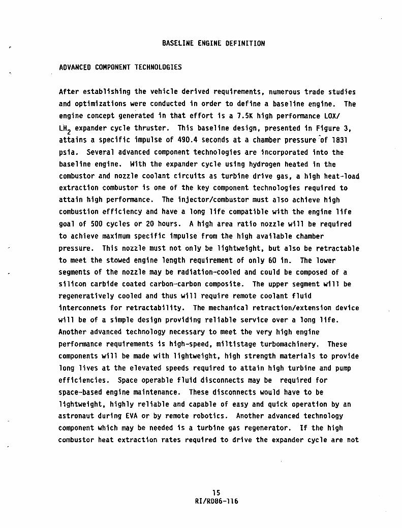
ADVANCED COMPONENT TECHNOLOGIES
After establishing the vehicle derived requirements, numerous trade studies and optimizations were conducted in order to define a baseline engine. The engine concept generated in that effort is a 7.5K high performance LOX/ LH2 expander cycle thruster. This baseline design, presented in Figure 3,
attains a specific impulse of 490.4 seconds at a chamber pressure of 1831 psia. Several advanced component technologies are incorporated into the baseline engine. With the expander cycle using hydrogen heated in the combustor and nozzle coolant circuits as turbine drive gas, a high heat-load extraction combustor is one of the key component technologies required to attain high performance. The injector/combustor must also achieve high combustion efficiency and have a long life compatible with the engine life goal of 500 cycles or 20 hours. A high area ratio nozzle will be required to achieve maximum specific impulse from the high available chamber pressure. This nozzle must not only be lightweight, but also be retractable to meet the stowed engine length requirement of only 60 in. The lower segments of the nozzle may be radiation-cooled and could be composed of a silicon carbide coated carbon-carbon composite. The upper segment will be regeneratively cooled and thus will require remote coolant fluid interconnets for retractability. The mechanical retraction/extension device will be of a simple design providing reliable service over a long life. Another advanced technology necessary to meet the very high engine performance requirements is high-speed, miltistage turbomachinery. These components will be made with lightweight, high strength materials to provide long lives at the elevated speeds required to attain high turbine and pump efficiencies. Space operable fluid disconnects may be required for space-based engine maintenance. These disconnects would have to be lightweight, highly reliable and capable of easy and quick operation by an astronaut during EVA or by remote robotics. Another advanced technology component which may be needed is a turbine gas regenerator. If the high combustor heat extraction rates required to drive the expander cycle are not
15 RI/RD86-116

:;0 ..... ........ :;0 c ...... co en en I ...... ...... en
co .... . .... C> V
E·-/ I
I I I I I I I i b. .. -
~I~ Rockwell ... ~ International
Rockeldyne Division
BASELINE OlV ENGINE 7500 LB THRUSTER
FIGURE 3.
\ \ \ \ \ \
=--:-l
TH RUST. LB 7500
CHAMBER PRESSURE. PSIA _1831
AREA RATIO 1080
SPECIFIC IMPULSE. SEC 490.4
LI FE. CYCLESlHR 500/20
ENGINE LENGTH. IN 117
... ,t
achievable. it may become necessary to boost the turbine drive gas temperature through the use of a regenerator. By placing a heat exchanger between the cooling jacket inlet and the turbine discharge. heat is transferred from the turbine exhaust gas to the coolant. In this manner. the turbine inlet temperature is elevated resulting in increased turbine power. A study (Appendix 3) has shown that a regenerator is undesirable. but should it become necessary. it would have to be compact. lightweight and provide high heat transfer efficiency. Components in the control and diagnostics area will also incorporate new technologies. Advanced sensors and engine controllers playa key role in ICHM system upon which the space-based maintenance philosophy is founded. As with the other technologies mentioned. these components must also be compact and lightweight while providing reliable operation over a long life. A summary of the advanced technologies incorporated in the baseline engine is provided in Figure 4.
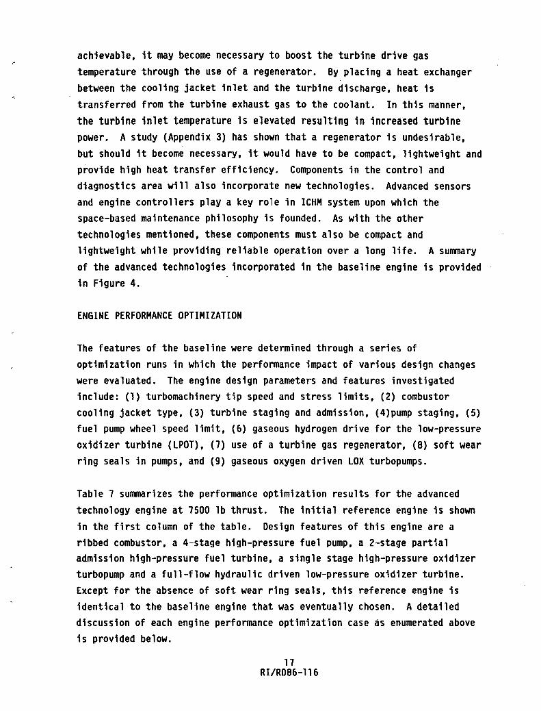
ENGINE PERFORMANCE OPTIMIZATION
The features of the baseline were determined through a series of optimization runs in which the performance impact of various design changes were evaluated. The engine design parameters and features investigated include: (1) turbomachinery tip speed and stress limits. (2) combustor cooling jacket type. (3) turbine staging and admission. (4)pump staging. (5) fuel pump wheel speed limit. (6) gaseous hydrogen drive for the low-pressure oxidizer turbine (LPOT). (1) use of a turbine gas regenerator. (8) soft wear ring seals in pumps. and (9) gaseous oxygen driven LOX turbopumps.
Table 7 summarizes the performance optimization results for the advanced technology engine at 7500 lb thrust. The initial reference engine is shown in the first column of the table. Design features of this engine are a ribbed combustor. a 4-stage high-pressure fuel pump. a 2-stage partial admission high-pressure fuel turbine. a single stage high-pressure oxidizer turbopump and a full-flow hydraulic driven low-pressure oxidizer turbine. Except for the absence of soft wear ring seals. this reference engine is identical to the baseline engine that was eventually chosen. A detailed discussion of each engine performance optimization case as enumerated above is provided below.
17 RI/RD86-116

;0 ..... ........ ;0 o ..... ex> ex> 0) I ..... ..... 0)
7.5K ENGINE COMPONENT TECHNOLOGIES eHIGH HEAT-LOAD
COMBUSTOR/INJECTOR
- HIGH Q EXTRACTION
- LONG LIFE
- HIGH COMB. EFF.
eHIGH AREA RATIO NOZZLE
STS/SPACE-BASED OTV F7'o/- .,.@
eHIGH-SPEED, MULTI-STAGE TURBOMACHINERY
- LIGHT WEIGHT
- ROTORDYNAMICS
-LONG LIFE
V - HIGH STRENGT~ .... TL'S It) ....
o .... ~ .41~ Rockwell .,.~ International
Rocketdyne Division
-HIGHLY RELIABLE
- LIGHT -WEIGHT
FIGURE 4.
1l ~
1\'
_ LIGHT WEIGHT
-LONG LIFE
- SIMPLICITY/RELlA .. LlTY
e ADVANCED CONTROL AND DIAGNOSTICS
- RELIABILlTYlSlMPLICITY
- COMPACTNESS
- LIGHT WEIGHT
-LONG LIFE
-COST - HEAT TRANSFER EFF •
- COMPACTNESS
- LIGHT WEIGHT

TABLE 7. RESULTS SUMMARY OF ENGINE OPTIMIZATION RUNS FOR ADVANCED TECHNOLOGY ENGINE AT 7500 LB THRUST
CA~e-NUMBER
CHOSEN AS
BASELINE
ENGINE PARAMETERS REFERENCE 2--- 3 --~- ---5---4=F-- 6 7 -8--------g
TURBOMACHINERY lIMITS AnY. (1) iJg(2) s:JL..A.L AnV. -·---~·---ADV. AnV. ADV-:- AnY. AnV. AnY. COMBUSTION TYPE RIBBED RIBBED ¥PERED ~IBBED RIBBED RIBBED RIBBED RIBBED RIBBED RIBBED RIBBED NO. OF HPFT STAGES 2 2 2 2 2 2 2 2 2 HPFT ADMISSION PARTIAL PARTIAL PARTIAL FULL PARTIAL PARTIAL PARTIAL PARTIAL PARTIAL PARTIAL PARTIAL NO. OF HPOP STAGES 1 1 1 .- 2 1 1 1 1 1 1 NO. OF HPFP STAGES 4 4 4 4 ;{ 4 3 4 4 4 4 HPFP SPEED LIMIT. RPM 200000 200000 200000 200000 200000 300000 3"00000 200000 200000 200000 200000 lPOT DRIVE TYPE F-F (3) F-F F-F F-F F-F r-r- r-r- GH2 F-F SOFT WEARL SEALS N/A N/A N/A N/A N/A N/A N/A Jl7A N/A YES YES GOX DRIVE N/A N/A N/A N/A N/A N/A N/A N/A N/A N7A YES CHAMBER PRESSURE. PSIA 1576 1387 1215 1214 1515 1626 . 1478 1534 1565 1831 TIll SPECIFIC IMPULSE. SEC 488.86 487.7 484.94 486.53 488.34 489.16 488.32 488.64 488.82 490.4 486.0
NOZZLE AREA RATIO 970 1042 909 914 847 994 975 1107 1048 1081 976 ;0 HPFT BYPASS. PERCENT 10 10 10 10 10 10 10 10 10 10 10 ...... ........ HPFTP EFF. PRODUCT. I 31.39 30.71 34.84 27.9 31.57 32.06 32.86 31.35 30.24 34.49 32.07 ;0
g t!; COMO. HEAT LOAD. BTU/SEC 6440 6402 3965 6366 6425 6453 6432 6432 6430 6502 6356 en NOZZLE HEAT lOAD. BTU/SEC 1416 1561 1721 1687 1428 1392 1485 1461 1431 1293 2019 I ...... REGEN. HEAT LOAD. BTU/SEC N/A N/A N/A N/A N/A N/A N/A N/A 43 N/A N/A
...... en HPFP SPEED. RPM 199661 118733 133255 200000 198894 247254 296159 195367 199345 199560 200000
HPFP EFFICIENCY. PRCENT 48.98 48.44 53.76 55.46 49.25 50.18 52.24 49.07 47.77 56.38 62.63 HPFP DIS. PRESSURE. PSIA 6559 5078 4164 4058 6472 6895 5335 6540 6908 7733 5747 HPFP DIAMETER. IN. 2.36 3.37 2.67 1.81 2.35 1.97 1.65 2.38 2.45 2.44 2.15 HPFP TIP SPEED. FT/SEC 2057 1749 1552 1580 2039 2128 2134 2032 2131 2125 1877
HPFT PRESSURE RATIO 2.23 1.91 1.97 1.8 2.20 2.27 1.89 2.22 2.38 2.31 3.02 HPFT EFFICIENCY. PERCENT 61.4 63.4 64.8 50.3 64.1 63.9 62.9 63.9 63.3 61.9 51.2 HPFT DIAMETER. IN. 1.99 2.95 2.33 2.21 2.16 1.81 1.30 2.05 2.05 2.14 2.08 HPFT VELOCITY RATIO .262 .258 .268 .346 .288 .292 .287 .266 .26 .276 .271 HPFT BlADE HEIGHT IN. .273 .29 .368 .087 .259 • 198 • 155 .259 .245 .243 • 120 HPFT ADMISSION. FAAcTION .225 • 198 .181 1.0 .218 .321 .806 .228 .226 .395 .775 HPFT AN**2.(IN-RPM)**2 E-l0 9.72 5.04 6.46 2.56 9.92 9.98 7.35 9.12 9.29 6.51 3.12 HPFT ON (MH-RPM) E-6 2.92 1.87 1.90 2.54 2.9 3.45 3.68 2.87 2.97 2.92 2.61 HPFT INLET TEMP. DEG-R 1129 1121 795 1103 1125 1129 1112 1133 1143 1119 890 HPFT PITCH VELOCiTY. FT/SEC 1731 1529 1357 1931 1881 1951 1679 1752 1788 1863 1814
(1) RElAXED TO A HIGHER VALUE (2) PARAMETER CHANGE UNDERLINED (3) FULL-FLOW HYDRAULIC DRIVE

Case 1: Turbomachinery Tip Speed and Stress Limits
This case, when compared to the reference case, indicates the benefits of advanced state-of-the-art turbomachinery tip speed and stress limits. In the reference case, the limits are relaxed to the higher values indicated in Table 8. Implementation of the advanced turbomachinery limits will require hybrid hydrostatic bearings and improved materials. With the same turbine inlet temperature, the increased tip speed and stress limits allows the wheel speed to be sharply increased. This results in better turbomachinery efficiencies and hence, higher chamber pressure, higher engine performance and smaller engine envelope. The chamber pressure advantage from advanced turbomachinery limits is 360 psia.
TA8LE 8. TUR80MACHINERY TIP SPEED AND STRESS LIMITS
1980 TURBOMACHINERY LIMIT S.O.A. (1) ADVANCED BEARING DN (mm-RPM) 1.9X10⁶ NONE TURBINE PITCH LINE VELOCITY (ft/sec) 1600. 2000 PUMP TIP SPEED (ft/sec) 1870. 2200 ANNULUS AREA x N2 (in-RPMM)2 8xlO 10X1010
Case 2: Combustor Cooling Jacket Configuration
Replacing the tapered smooth-wall combustor with an advanced ribbed combustor significantly increases the coolant heat load which increases the power available to the turbine. This results in a higher chamber pressure and specific impulse. A ribbed combustor provides about 60% more heat load than a tapered combustor (Case 2 compared to Case 1) and results in a chamber pressure increase of 170 psia. In support of this effort, point designs of the combustor and nozzle coolant jacket were generated.
20 RI/RD86-116

Contours for both the combustor and nozzle were first determined. The combustor geometry was then subjected to a boundary layer analysis to determine hot-gas heat transfer coefficient profiles and to a thermal analysis to determine coolant-channel geometry heat loads and coolant pressure drop for the required life of 1200 cycles. Details of the point design are presented in Appendix 2.
Case 3: Turbine Staging and Admission
The use of a single stage "full admission high-pressure fuel turbine reduces the engine chamber pressure and specific impulse significantly because of two effects. First, the full arc of admission significantly reduces the turbine blade height. Second, the single stage turbine requires a higher stage pressure ratio which reduces the blade height further. The large decrease in blade height results in a heavy,penalty on the turbine efficiency and hence, a significant loss in engine performance. If speed wasn't held at 200,000 rpm as a limit, it would also have required higher speeds for the same turbomachinery limits. A 14 point turbine efficiency deficit is created which reduces chamber pressure by 362 psia from the reference case.
Case 4: Pump Staging
An increase in the number of main fuel pump stages results in a definite increase in the pump discharge pressure. This consequently raises the turbine pressure ratio such that the increased pump power requirement can be met. The increase in turbine pressure ratio is not large enough to offset the increase in the pump discharge pressure so that a significant increase in chamber pressure results (148 psia, compare Case 4-F and 5).
The oxidizer pump staging has a smaller and opposite impact on the engine performance than the fuel pump. Increasing the oxidizer pump staging from one to two results in a decrease in chamber pressure (61 psia) and in specific impulse (compare Case4-D to reference).
21 RI/RD86-116

Case 5: Fuel Pump Wheel Speed Limit
For most cases considered, fuel pump rpm was limited to 200,000. An increase over this limit does increase the optimum pump operating speed, but, results in a very small increase in the turbomachinery efficiencies since the tip speed and stress limits are unchanged. Therefore, the impact of pump wheel speed limit on the engine performance is not significant (compare Case 5 with the reference case).
Case 6: Gaseous Hydrogen Drive for LPOT
In this configuration, a gaseous hydrogen driven low-pressure-oxidizer turbine (LPOT) located in parallel with the high-pressure oxidizer and low-pressure fuel turbines is used to replace the full-flow hydraulically driven LPOT. This arrangement would allow operation of boost pumps in the tank-head idle mode to speed up ehgine conditioning. Since the power required by the low-pressure oxidizer pump is very small, the impact of gaseous hydrogen drive for the LPOT on engine performance is not significant. Although the use of gaseous hydrogen drive for the LPOT can be advantageous during engine start, additional inter-propellant seals would be required for the low-pressure oxidizer turbopump.
Case 7: Turbine Gas Regenerator
The benefit of adding a turbine gas regenerator between the cooling jacket inlet and turbine discharge was also investigated for the reference engine. The purpose of the regenerator is to transfer heat from the turbine exhaust gas to the coolant. increasing the turbine inlet temperature and in that manner increase turbine power. The increase in combustor coolant inlet temperature, however,~ increases the coolant velocity through the cooling jacket which results in a large jacket pressure loss. The large pressure loss experienced in Case 7 offsets the benefits which resulted from regeneration. A detail optimization of the coolant jacket channel design at this particular condition is required before a final answer can be given in this area. An additional study was conducted subsequently in which reduced jacket pressure drops were investigated. Details of this study are presented in Appendix 3. Results of this study show that with the addded
22 Rl/R086-ll6

complexity and engine weight, the minimal increases in performance gained do not warrant the use of a hydrogen recuperator even if major reductions in the combustor coolant jacket pressure drop were possible.
Though these investigations indicate that a hydrogen regenerator is not desirable, it still may become necessary should the combustor heat extraction rates prove to be insufficient. Therefore, the recuperator will still be included as an option to be further considered.
Case 8: Soft Wear Ring Seals
The high-speed OTY turbopumps are relatively small and clearances between stationary and rotary parts become a significant percentage of the flow passage area. The resulting parasitic leakage flow losses can be reduced by close clearances. Soft-seal polymer materials offer the potential of extremely close-clearance wear rings with elimination of metal-to~etal rubbing and its adverse consequences on the propellants and rotating parts. Based on detailed efficiency loss analysis of two configurations using very small clearances (order of one thousandth), a correlation was developed for prediction of OTY pump efficiencies using soft seals.
The performance was improved significantly over that of the reference engine by inclusion of soft wear ring seals. Based on this improvement, Case 8 was chosen as the baseline OTY engine upon which all subsequent studies were conducted.
Case 9: Oxygen Drive HPOT
In this case, an engine utilizing a gaseous oxygen driven LOX turbopump was investigated. For this configuration, the energy for the turbine drive gas is supplied by heating the oxygen in the nozzle cooling circuit. The LH2 turbopump is still driven by hot hydrogen gas but this drive gas is heated only in the combustor cooling circuit. Soft wear ring seals were also included in this case, therefore, performance is to be compared with the baseline engine (Case 8) as opposed to the reference engine. Significant decreases in performance for the oxygen driven HPOT case. were observed. Chamber pressure is down 690 psia and specific impulse down 4.4 seconds with
respect to the baseline configuration. The poor performance exhibited by
23 RI/RD86-l16

the oxygen driven case is due to the limited amount of energy provided to the oxygen in the nozzle cooling circuit. If additional energy could be supplied to the oxygen, possibly with injector heat exchanger baffles, this performance would improve.
In summary, based on the series of optimization studies described above, Case 8 was chosen as the baseline OTV engine. A description of this engine including salient features and performance characteristics is provided in Table 9 •.
ENGINE THRUST STUDY
After definition of the baseline 7.SK engine, a study was conducted to evaluate the effect of thrust upon engine weight, length and performance. For this effort the technology level was held constant. A fixed overall nozzle expansion ratio of 1000:1, percent length of 90% and breakpoint £
(regen- erative to radiation cooled) of 4S0 was used. These fixed values were chosen from the optimized 7.SK baseline engine. The purpose of this study was to supply the vehicle contractors with parametric data should required engine thrust level change due to revisions in NASAls orv mission model.
Engine performance drops off significantly at the lower thrust levels due to lower turbopump efficiencies and greater kinetic losses. Single engine weight increases linearly with thrust. Detailed results of this study are presented in graphical form in Appendix 4. Other parameters addressed include engine cluster weight, payload, chamber pressure, engine envelope, and turbopump efficiencies.
CONTROL SYSTEM ASSESSMENT
The control system for the baseline engine was evaluated. Four engine control system concepts, Table 10, were assessed to determine the one most suitable for near-term OTV engine. 8ased on the functional control aspects and other features, including cost, full range controls were considered to be the most desirable choice.
24 RIIRD86-1l6

TABLE 9. BASELINE ENGINE DESCRIPTION
• ADVANCED TURBOMACHINERY LIMITS • HIGH HEAT-LOAD RIBBED COMBUSTOR • TWO-STAGE PARTIAL ADMISSION FUEL TURBINE • FOUR-STAGE HIGH PRESSURE FUEL PUMP • SINGLE STAGE HIGH PRESSURE OXIDIZER PUMP • FULL FLOW HYDRAULIC DRIVEN LOW-PRESSURE OXIDIZER TURBINE • HYDROGEN REGENERATOR (IF REQUIRED) • SOFT WEAR RING SEALS ON PUMPS • HYDROGEN DRIVEN OXIDIZER TURBOPUMP
CHAMBER PRESSURE, PSIA 1831 SPECIFIC IMPULSE, SEC 490.49 % LENGTH* 94
NOZZLE AREA RATIO 1081 HPFT BYPASS, PERCENT 10 HPFTP EFF. PRODUCT, % 34.9
6hf, HEAT OF FORMATION, 1.62 Kca1/gmo1
COMB. HEAT LOAD, BTU/SEC 6502 NOZZLE HEAT LOAD, BTU/SEC 1293
LOX MAIN PUMPS: SPEED, RPM 63313 EFFICIENCY, PERCENT 69.69 DIS. PRESSURE, PSIA 3119 DIAMETER, IN. 2.37 TIP SPEED, FT/SEC 654 SPECIFIC SPEED 865 MAIN TURBINES: PRESSURE RATIO 1.16 EFFICIENCY, PERCENT 61.5 PIT DIAMETER, IN. 4.05 VELOCITY RATIO .41
. 1ST BLADE HEIGHT, IN. .27 ADMISSION, FRACTION .264 AN**2, (IN-RPM) **2 E-l0 1.579 OM, (MM-RPM) E-6 .743 INLET TEMP., DEG-R 982 PITCH VELOCITY, FT/SEC 1119
25 RIIRD86-116
LH2
199560 56.38 7133 2.44 2125 749
2.31 61.9 2.14 .28 .14 .395 6.506 2.923 1119 1863

TABLE 10. ENGINE CONTROLS SYSTEM CONCEPTS DEFINITION
A. MINIMUM ELECTRONIC SYSTEMS NO CONTROLLER MECHANICAL SEQUENCING MONITORING INSTRUMENTATION FOR REUSABLE ENGINE REDLINE MONITORING FOR MAN-RATING CHECKOUT BY OFF-ENGINE MEANS
B. OPEN LOOP ELECTRICAL SEQUENCE CONTROL NO VALVE POSITIONING CONTROL MONITORING INSTRUMENTATION AND REDLINE MONITORING CHECKOUT AND STATUS MONITORING ON ENGINE
C. MAINSTAGE TRIM CONTROLS ELECTRICAL SEQUENCE CONTROL NO VALVE POSITIONING CONTROL DURING START AND SHUTDOWN MONITORING INSTRUMENTATION AND REDLINE MONITORING PERFORMANCE INSTRUMENTATION FEEDBACK DURING MIS TO TRIM F & MR CHECKOUT AND STATUS MONITORING BY ENGINE
D. FULL RANGE CONTROLS CONTROLLER PERFORMING VALVE POSITION CONTROL FEEDBACK TO CONTROL F & MR AS REQUIRED MONITORING INSTRUMENTATION AND REDLINE MONITORING PERFORMANCE INSTRUMENTATION CHECKOUT & STATUS MONITORING BY ENGINE
26 RI/RD86-116

The near-tenm control system for the OTV advanced expander cycle engine includes a variety of components, and impacts all phases of engine operation. Therefore, the selection of this system must consider a wide range of related areas. Specific areas of assessment included: control point selection, steady state performance, starts and shutdown, redundancy issues, controller, valves, actuators, and instrumentation. This near-term control system constitutes the baseline system from which the advanced ICHM will evolve.
Control Point Selection
Figure S is a simplified schematic showing only the primary flow paths. The recommended primary control pOints are the main oxidizer valve (MOV) and the turbines bypass valve (TBV) which control the mixture ratio and thrust, respectively. The main fuel valve (MFV) is used for start and shutdown control and the oxidizer turbine bypass valve (OTBV) is used to achieve satisfactory operation during powered idle mode. The selection of the MOV and TBV as the main control points was based on a sensitivity analysis conducted on the 7.SK engine.
Though the MFV is a good thrust control point and would obviate the TBV, the additional pressure loss introduced is greater a penalty than the benefits gained by removing the TBV flow. In addition, pump inlet shutoff-isolation valves could not be used for thrust or mixture ratio control without causing pump cavitation. Thus the MOV and TBV are the logical control point selections.
Steady-State Performance
An engine with no feedback control (open loop) should be expected to experience 20% thrust variations over the life of the engine and 7% thrust variations with a given mission, while a closed loop controlled engine could be expected to maintain thrust within 2%. Similarly, mixture ratio (MR) could be controlled to within 0.1 unit over the engine life with feedback control,
'but if ran open loop, the engine could experience a 0.3 unit variation in a given mission and O.B unit variation over the life of the engine. A summary of the variations is presented in Table 11.
27 RI/RDB6-116

"11 o ;0 ~ 0-o IX) . OJ • -w ;0 m ::-(J'I
.!.i (J'I
;;c t-4 ....... ;;c c ~ I ..... ..... m
N 00
HIGH PRESSURE OXIDIZER TURBO PUMP HYDRAULIC LOX TURBINE
FIGURE 5. SERIES TURBINE BASELINE OTV ENGINE SCHEMATIC -MAIN PROPELLANT CONTROL VALVES
LOW PRESSURE
"'--r--' OXID TURIO PUMP
OXID TURBINE
TURBINES BYPASS VALVE
LOW PRESSURE '----r--' FUEL TURBO PUMP
HIGH PRESSURE FUEL TURBO PUW
TURBINE GAS REGENERATOR {COLDSIDEI
COMBUSTOR COOUNGAND HEAT EXCHANGER
NOZZLE COOUNGAND HEAT EXCHANGER
-a ~
:D :rJ g 0 ~ n . ~ f CD . -C -3: :; a- S' ~ 3
& i

TABLE 11. EXPANDER CYCLE PERFORMANCE
IN-RUN AND RUN-TO-RUN IN RUN
ENGINE CONTROL THRUST MR THRUST MR CONCEPT VARIATION VARIATION VARIATION VARIATION
OPEN-LOOP 20% 0.8 UNITS 7% 0.3 UNITS (A & B)
CLOSED-LOOP 2% 0.1 UNITS 2% 0.1 UNITS (C&D)
Start and Shutdown
Start and shutdown impose extreme operating conditions on the engine and maintaining proper relationships of pressures and temperatures is extremely important for reliability and long life of the 7.SK engine system. Positioning and controlling the engine system valves properly can be realistically accomplished only with an electronic controller. Twenty-two valves on the engine must be sequenced to open or close in the correct sequence during start, mainstage and shutdown. Actuator requirements, as defined in Table 12, result in actuator types for engine control that cannot be open loop positioned. Some type of position control must be employed to ramp the valves slowly and reliably, in a repeatable manner. It must also be able to adapt as new requirements are generated or system limits and problems are encountered. Thus, start and shutdown requirements not only define an electronic sequence controller, but a valve position control and reference command capability. Even though sequence and valve position control are required, no closed loop operation appears to be required for start and shutdown. However, with valve position control available, closed loop engine control can be implemented during any other phase of engine operation where closed loop control may be required, such as for MR control during mainstage.
29 RI/RD86-116

" o ::tJ ~ 0-o cr OJ . w ::tJ m < (J1
.!.i (J1
;::c ...... ......... ;::c o eN ex> 0 0'1 I ..... ......
0'1
ENGINE CONTROL CONCEPT
A
B
C
.
D
TABLE 12. ACTUATOR REQUIREMENTS
VALVE POSITIONING REQUIREMENTS
SLEWRATE - PRECISION
START CUTOFF
MFV Ramp between stops Same as 75%/SEC±25%/SEC Start
MOV 20%/SEC±5%/SEC.±2 1/2% 50S/SECtlOS/SEC 2 intermediate positions ramp closed
lURB 40%/SEC±lO%/SEC.t2 1/2% No Req'mt BYPASS 2 intermediate positions
OXIO TURB 60%/SEC±40%/SEC.±2 1/2% . No Req'mt BYPASS 1 pos~tion besides open
(SAME AS "A" ENGINE FOR ALL REQUIREMENTS) I
MFV START AND CUTOFF f
MOV HAVE SAME
TURB BYPASS REQUIREMENTS AS I'A"
OXIO TURB BYPASS
MFV (SAME AS "A" ABOVE)
MOV 50%/SEC with 0.5% Resolution .'
TURB BYPASS 50%/SEC with 0.5% Resolution.
OXIO TURB 50S/SEC with 0.5% Resolution BYPASS
MAl NSTAGE
Full Open
t 1/2S ,
t 1/2%
± 1/2S
Full Open
0.5S resolution :
0.5S resolution .
0.5S resolution : .
Full Open ;
0.5S resolution
O.SS resolution
0.5% resolution
-a ~ r 51 f n
f f . -CI -3: 3" . .... 0' CD :II 3
i !!.

The advantages of full range controls also apply to start and shutdown
operation as can be seen in Table 13.
Redundancy
Four control system redundancy configurations were evaluated. The dual-dual cross-strapped system, Figure 6, was chosen as the most desirable. In evaluating the redundancy requirements, the ultimate issue is mission success. To achieve success, components must be reliable enough to work for the,entire duty life, or redundancy must be provided for failed components. In examining the control system components, the controller itself is extremely reliable regardless of having to operate several hours for each hot fire test. Even with the high level of reliability of the controller, electronics are subject to random failure, thus some kind of redundancy for the controller is still required.
At the other extreme, engine system sensors experience a relatively high rate of failure due to the severe environments associated with the sensing locations. Thus additional redundancy for critical sensors is required. Reliability data from the SSME was used as a guide in performing this evaluation.
Power Distribution
The power distribution system inherently does not lend itself to the variety of options afforded to other aspects of the control system. For example, while controller subsystems such as the computers and input-outputs electronics can be reduced greatly in size by using the latest microelectronic technology, the power supply is not very amenable to miniaturization.
31 RI/RD86-116

ENGINE CONTROL CONCEPT
A
B
C
D
TABLE 13. EXPANDER CYCLE ENGINE START AND SHUTDOWN REQUIREMENTS
OPERATIONAL CHANGES
CHANGES REQUIRE MECHANICAL PARTS TO BE REDESIGNED
SEQUENCE TIME CAN BE PROGRAMMED. OPENING RATES OR AREA CHANGES OF CONTROL POINTS REQUIRE MECHANICAL PART REDESIGN
SEQUENCE TIMES CAN BE PROGRAMMED. OPENING POINTS REQUIRE MECHANICAL PART REDESIGN
CAPABLE OF ADAPTING TO LARGE CLASS OF REQUIRED CHANGES BY CHANGES TO SOFTWARE
32 RIIRD86-116
TEST VARIATIONS
TEST-TO-TEST VARIATIONS MUST BE ACCEPTED OR COMPLEX MECHANICAL COMPENSATION SYSTEMS DESIGNED AND DEVELOPED.
TEST-TO-TEST VARIATIONS MUST BE ACCEPTED OR COMPLEX MECHANICAL COMPENSATION SYSTEMS DESIGNED AND DEVELOPED.
TEST-TO-TEST VARIATIONS MUST BE ACCEPTED OR COMPLEX MECHANICAL COMPENSATION SYSTEMS DESIGNED AND DEVELOPED.
CONTROL CAN BE USED TO ABSORB VARIATIONS.

" o :0 3::
'" o QI) . OJ . w :0 m ::-U1 ..!.J U1
;0 ...... '-;0 Ow CPw 0"1 I ...... ......
0"1
POWER SUPPLY
POWER SUPPLY
Figure 6. Dual-Dual Redundant Cross-Strapped Systems
SENSOR A1
SENSOR A2
SENSOR 81
SENSOR 82
INPUT ELECTR
INPUT ELECTR
PRO
DIGITAL COMPUTER
DIGITAL COMPUTER
OUTPUT ELECTR
SOLENOID OR
ACTUATOR
OUTPUT ,SOLENOID
ELECTR OR ACTUATOR
- GREATEST CHANCE OF MISSION SUCCESS
- STRENGTHENS WEAKEST LINK
-SOME EXPERIENCE ON SSME
CON
-NOT FO/FO/FS AT ALL LEVELS
CHANNEL A
CHANNELB
~ • :II :::D o 0 n 0 =- ~ f ~ CD = o _
3: a. !!. (1)
g 3 CD 0: g !!.

The distribution -configurations that were evaluated include: (1) AC/DC power conditioning by controller; (b) direct DC from stage, power conditioned by controller; and (c) direct DC to controller, actuator, solenoids and igniters. Configuration (c) requires the smallest power supply and is the recommended option for the 7.SK engine. However, vehicle design factors, such as locations of the fuel cells, must be considered before the physical characteristics of the power distribution system, such as size, weight, and voltage, can be resolved.
Controller
Associated with the four control system concepts of Table 10, four controller options were considered: (a) no controller; (b) minimum controller with open loop engine controls; (c) con~roller with mainstage trim controls; and (d) a full range controller with closed loop engine controls. When total engine performance, reliability, cost and other considerations as indicated in Table 10 are taken into account, option (d) becomes the most desirable choice.
Valves
An evaluation was conducted to define the type of valves best suited for each location required. A total of 30 valves and controls were identified for complete engine control. They are summarized by valve type, location and quantity in Table 14.
A~1uators
The actuator requirements for the primary control points were defined in Table 12 for the four control options considered. It is recommended that the primary control point actuators be electrically actuated and have a pneumatic backup. Electric actuators provide the positive, repeatable, position control required for reliable and repeatable start and shutdown. The electric actuators also lend themselves to actuator redundancy. Redundant electric actuators, though, would require additional weight and complexity.
34 RI/RDB6-116

TABLE 14. VALVE SUMMARY
VALVE TYPE QUANTITY
• BALL VALVES, HIGH PRESS., PNEUMATICALLY ACTUATED (1) MFV, (5) GOV 2
• BALL VALVES, HIGH PRESS., SERVO-ACTUATED (2) MOV, (3) FTBV, (4) OTBV 3
• PROPELLANT ACTUATED VALVE (7) HIE SHUNT VALVE
• PROPELLANT SOLENOID VALVES (6) CCV, (8) & (9) IGNITER VALVES 3
• TANK PRESS. CHECK VALVES, (10) & (11) 2 • PREVALVE BALL VALVES, (12) & (13) 2 • PURGE SOLENOID & CHECK VALVES (14-23) 10 • PNEUMATIC CONTROL SOL. VALVES & SERVOS
(24, 25, 26, 27, 28, 29, 30) 7
30 TOTAL
THROTTLING AND STABILITY
Off-design operation of the 7.5K lb thrust baseline was examined using an off-design computer model. The objective of this study was to establish the range of throttling free of pump and feed system instability. Thrust levels in the range of 10-100 percent of nominal and mixture ratios in the range 4-7 were examined. Ideal pump HQ characteristics were used. These will be updated when point-design characteristics are available. No attempt was made to assess pump critical speed impact on throttling, since detail pump design is not available yet. Results of the study are summarized in Table 15.
35 RI/RD86-116

TABLE 15. OTV 7.5K ENGINE OFF-DESIGN SUMMARY
OFF-DESIGN THRUSTS AND MIXTURE RATIOS
THRUST PREDICTED ENGINE 1%. 9F NOMINAL) MIXTURE RATIO OPERATION
100 7 STABLE 20 6 OR LESS STABLE 12 6 UNSTABLE 12 4 OR LESS STABLE 10 4 STABLE
All operating points examined are also shown on the high pressure fuel pump H-Q map in Figure 7. Stable operation is predicted at nominal thrust and mixture ratio of 7:1. This mixture ratio is an off-design vehicle requirement.
At a mixture ratio of 6:1 the engine will operate stably down to a thrust level of 20 percent of nominal value. This is indicated in Figure 7 by a pump operating point to the right of the zero-slope line of the H-Q curves. As indicated by the 12 percent thrust point, the zero-slope line is intercepted at a thrust level below 20 percent of nominal.
Stable operation below 20 percent thrust level is achieved by lowering mixture ratio to 4:1 or below. In the interest of maintaining high performance, a mixture ratio of 4:1 is chosen. The lower mixture ratio increases the relative flow through the pump, shifting the operating point to the right of the zero H-Q line slope and returning stability to the flow. The zero slope is used as a guide. More insight into the stability condition can be obtained with a transient model of the system that includes the coolant jacket resistance. With this model an assessment of the nature of the instability (bounded or diverging) can be made.
36 RI/R086-1l6

Figure 7.
PREDICTED FUEL PUMP PERFORMANCE FOR 7500 LB ENGINE
o o 50 100 150 200 250 300
PUMP VOLUMETRIC FLOW~ GPM

Table 1& present~ a summary of important engine operating parameters at off-design conditions.
TABLE 1&. 7.5K LB ENGINE BALANCE SUMMARY AT OFF-DESIGN THRUSTS
ENGINE MIXTURE RATIO CHAMBER PRESSURE, PSIA ENGINE SPECIFIC IMPULSE, SEC ENGINE THRUST, LB COMBUSTOR HEAT LOAD, BUT/SEC NOZZLE HEAT LOAD, BTU/SEC T/C FUEL FLOWRATE, LB/SEC T/C OXIDe FLOWRATE, LB/SEC FUEL PUMP SPEED, RPM FUEL PUMP EFFICIENCY. % FUEL PUMP HORSEPOWER FUEL PUMP DISCHARGE PRESSURE, PSIA OXIO PUMP SPEED. RPM OXID PUMP EFFICIENCY. % OXID PUMP HORSEPOWER OXID PUMP DISCHARGE PRESSURE, PSIA FUEL TURBINE INLET TEMP, oR FUEL TURBINE FLOWRATE, LB/SEC FUEL TURBINE PRESSURE RATIO FUEL TURBINE EFFICIENCY OXIO TURBINE INLET TEMP, oR OXID TUR8INE FLOWRATE, LB/SEC OXID TURBINE PRESSURE RATIO OXID TURBINE EFFICIENCY
AND MIXTURE RATIOS
THRUST. % OF NOMINAL DESIGN POINT 100 & 7 157& 153& 488.8& 482.9 7500 7500 &440 &0&0 141& 1325 13.14 1.917 2.15 13.571 199&&1 18773& 48.98 48.81 1525 1234 &559 5928 &6463 63503 62.03 61.&3 1915 188 2705 ?394 1129 1186 1.932 1.&48 2.23 2.08 64.1 63.4 989 1051 1.462 1.359 1.118 1.118 57.6 55.8
38 RIIRD86-116
20 & 321 47&.3& 1500 1727 358 .445 2.01 77&53 38.07 74 1098 23529 52.2& 7.4 384 1354 .204 1.&1 42.7 1282 .1 & 1 1.07 35.2
12 4 205 481.17 900 1224 2&0 .3&9 1.494 &5799 37.56 45 795 20036 40.2 4.0 283 115& .155 1.60 40.1 1098 .117 1.07 34.2

FAILURE MODE EFFECTS AND RELIABILITY ANALYSES REVIEW
FMEA AND RELIABILITY ANALYSES
Upon completion of the baseline engine definition, a failure mode and effects analyses and reliability analyses were conducted under the ICHM subtask E.l. Review of these analyses and their application in FME mitigation and reliability improvement were one of the major efforts completed during the Phase I study. The relation of this review to the overall study can be seen in the logic diagram previously presented in Figure 1. Results of this effort were incorporated into the development of advanced engine concepts and ultimately into the updated engine design. An overview of the approach taken in this review and its application is presented in Figure 8.
The scope of the FMEA was defined as encompassing the major engine components which include the injector, combustor, fixed regenerative cooled and retracable radiation cooled nozzle, and the nozzle retraction mechanism itself. In addition, several major engine systems were considered. The heat transfer systems included the chamber coolant circuits, LOX heat exchanger and the hydrogen regenerator. Components of the turbine drive systems covered were the low and high pressure fuel and oxidizer turbines and the associated bypass and shutoff valving. Propellant feed systems analyzed included the low and high pressure fuel and oxidizer pumps and the inlet and main propellant valves. Operational modes addressed in the FMEA and reliability analysis were tank-head idle, pumped idle, mainstage, and transitions during start and shutdown. Within this scope, the FMEA identified 112 separate modes of failure and their effects on engine operation. Causes of each of the failures were explained, means of detection defined, and the adequacy of response time evaluated. Finally, each failure mode was assigned a criticality number based on the severity of its impact upon operational capability.
39 RI/RDB6-116

:;c ...... ....... :;c o ~ ex> a m I ...... ...... m
FAILURE MODE EFFECTS AND RELIABILITY ANALYSIS REVIEW AND APPLICATION
0) ,... ,... , ,...
FMEASCOPE
COMPONENTS
INJECTOR COMBUSTOR FIXED NOZZLE EXTENDIBLE NOZ. NOZZLE DR IVE
SYSTEMS
HEAT TRANS • TURB. DRIVE OXYGEN FEED FUEL FEED
OPERATIONAL MODES
MAINSTAGE PUMP IDLES TANK-HEAD IDLE START AND
SHUTDOWN
0)" ~
1II1~ Rockwell p.~ International
Rockeldyne Division
FME MITIGATION FAILURE MODES AND EFFECTS ANALYSIS AND RELIABILITY
FAILURE EFFECTS PROPAGATION IMPROVEMENT
MODES AND RATES ~ IDENTIF. CRITI- .
... COMPONENT CALITY DESIGN EVOLUTION
ENGINE CYCLE ... DESIGN EVOLUTION
..... REDUNDANCY .'P
ICHM DESIGN EVOLUTION
RELIABILITY ANALYSIS
SERVICING FAILURE START AND RELIABIL. . (MAINTENANCE) RATES SHUTDOWN ASSESS. ~
ANALYSIS ANALYSIS
~
FIGURE 8.

A sample of the detailed output provided by the FMEA is presented in Appendix 5. A summary of the FMEA is provided in Table 11, in which the number of failure modes for each component in each criticality rating is tabulated. The criticality numbers are defined as follows:
CRITICALITY
(1 )
NO. ENGINE EFFECT VEHICLE EFFECT MISSION EFFECT
1 Major uncontained damage Significant damage Mission abort(l) to an engine subsystem to adjacent equip- low probability of or component resulting ment and/or vehicle loss, crew in widespread engine vehicle probable. death or injury. damage.
2 Significant contained Damage to adjacent Mission abort(l) damage to a vital engine equipment or subsystem or component vehicle highly sufficient to render it improbable. inoperative or its con-tinued operation hazardous
3 Performance Degradation None Mission abort(l) or notable damage to com- conditionally ponent/subsystem. Con- dependent. tinued operation condi-tionally acceptable.
4 Minor failures fully None Delay until tolerated by continued resolved at operation at an accept- mission start. able hazard level. Minor propellant leakage from flanged joints.
5 Nuisance failures. None Correct at next routine main-tenance.
Mission abort for criticality 1 through 3 failures applies only on outboard phases prior to OTV payload disposition. After abort, emphasis is placed on safe return of the vehicle/crew regardless of payload disposition.
41 RIIRD86-116

;0 ...... , ;0 CI~ OON 01 I ..... .....
01
TABLE 17.
OTV ENGINE CRITICALITY SUMMARY
o ("II
SYSTEM
ENGINE SYSTEMS THRUST CHAMBER
INJECTOR CHAMBER FIXED NOZZLE EXTEND. NOZZLE NOZ. DRIVE
HEAT TRANSFER SYS. CHAMBER COOL. LOX HEX REGEN
TURBINE DRIVE SYS. LPFT HPFT HPOT HPOT-LPOT TBV OTBV TSV
OXYGEN FEED SYS. INLET VALVE LPOP HPOP MOV
FUEL FEED SYS. INLET VALVE LPFP HPFP MFV
TOTAL
• II. Rnckwp-II
Rockeldyne Division
NO. OF MODES
5
5 3 3 1 2
2 3 3
5 5 6 6 3 3 7
7 7 7 2
7 6 6 8
112
NO.OF NO.OF NO.OF NO.OF CRIT.1 CRIT.2 CRIT.3 CRIT.4
3 1 1
1 1 3 2 1 1 1 1
1 1 1
2 1 2
1 2
4· 1 3 1 1 4 1 1 4 1 1
2 1 2 1
6 1
1 2 4 1 5 1 5 1 1 1 1
2 4 1 5 1
4 1 1 4 4
33 34 33 12
NO. OF CRIT.5
!
0

In the reliability analysis which was done in conjunction with the FMEA, single start reliabilities and failure rates for major engine components were determined. In that analysis, the engine was broken down into six components. These subsystems were: combustion devices, turbomachinery, controls/valves, electrical/flight instrumentation, controller, and the systems, line, and ducts. Failure apportionment. as defined as percentage of failures for the respective component during a 12 minute burn. were calculated. From that information, an overall baseline engine start reliability and failure rate were estimated.
Review of the FMEA and reliability analyses provided important direction and information required in the subsequent FME mitigation and reliability improvement studies. By addressing problem areas flagged out in this review, the baseline engine will evolve into a more reliable and serviceable engine in an efficient manner.
FME MITIGATION AND RELIABILITY IMPROVEMENT
Approach
Results of the FMEA and reliability analysis review were were then used in FME mitigation and reliability improvement studies. In that effort, methods of improving engine reliability and mitigating failures were evaluated. Approaches considered included component design evolution, engine cycle design evolution. redundant components, ICHH design evolution, and servicing/maintenance scenerios.
These methods for improvement are summarized in Table 18, and will be addressed individually in the following sections. Each category in itself has several approaches which were investigated.
43 RI/RD86-l16

;:0 .......
.......... ;:o~ c~
~ I .......
....... 0'1
TABLE 18.
FME MITIGATION AND RELIABILITY IMPROVEMENT
N N .... , .... 0) o:;t
COMPONENT DESIGN EVOLUTION
ENGINE AND CYCLE DESIGN EVOLUTION
REDUNDANCY
ICHM EVOLUTION
SERVICING
~l~ Rockwell .,.~ International
Rocketdyne Division
-VALVES ACTUATION
-TYPES
-MARGINS
-TURBOMACHINERY
-DERATED ENGINE
-MODULAR PACKAGING
-THRUST AND MR CONTROL DURING TRANSIENT
- EMERGENCY SHUTDOWN (TSV)
-SENSORS
-HIGH PRESSURE TURBOMACHINERY
-ELECTRICAL HARNESSES
-ADVANCED SENSOR SPECIFICATIONS
-CONTROLLER DESIGN AND LOGIC
-CONTROLLER LOCATION
-REMOVAL AND REPLACEMENT
-PACKAGING FOR MAINTAINABILITY
-CHECKOUTS (AUTOMATION AND TELEPRESENCE)

Examples of failure mitigations through the engine and ICHM design are
presented in Table 19. As can be seen, failure mode effects have been reduced in criticality or eliminated entirely by design modifications. The ICHM modification failure mode criticality designations are as follows:
CRITICALITY NO. ENGINE EFFECT VEHICLE EFFECT MISSION EFFECT
A Safe shutdown of engine None Mission abort(l) before uncontained damage results.
B Safe shutdown of engine None Mission abort(l) before significant con-tained damage results.
C Reduced power level None Mission abort(l) operation.
D Parallel or standby None Delay until redundant system assumes resolved at function - normal engine mission start. operation continues.
Component Design Evolution
Two approaches were addressed for FME mitigation and reliability improvement through component design evolution. These included improvements in the reliability of value actuation and turbomachinery operation. The primary failure mode of the electric actuated valves to be used in the.QTV engine is contamination-induced stalling of the drive actuators. Potential solutions realized through design modifications are to increase motor force margins in order to overcome friction, provide better contamination control and to reduce contamination sensitivity of the mechanism. The most probable failure mode of the inlet fuel and oxidizer valves is the failure of the pneumatic actuator thus preventing the opening of the valve. A potential design solution relies upon the use of electric or squib backup actuators. A summary of these valve related improvements is presented in Table 20.
45 RI/RDB&-ll&

;c .......
........ ;c 0-1==> OJ en en I I-' I-' en
TABLE 19.
FAILURE MITIGATION THROUGH ENGINE AND ICHM DESIGN
REF. NO.
0101
0102
0103
0104
0105
.... N .... .
FMEA
FAILURE MODE
LPFTOR HPOT DAMAGE VIA DEBRIS FROM HPFT FAILURE
LPFTOR HPOT DAMAGE VIA DEBRIS FROM HPFT FAILURE
TRANSIENT M.R. EXCURSIONS ERODE LOX POST TIPS
NORMALL Y OPEN GOVCAUSES LOX RICH START
EMERGENCY SHUTDOWN CONSTRAINED BY VALVING OPTIONS
~I~ Rockwell ".~ International
Rocketdyne Division
CRIT. NO.
1
1/A
3
2
1
FAILURE MITIATION APPROACHES
DESIGN ICHM ENGINE AND SERVICING REDUNDANCY
COMPONENT CYCLE SENSORS CONTROL ,
ADD DEBRIS CATCHER DOWN· STREAM OF HPFT
PREDICT LIFE REMAINING FROM DEFLECTO· METER AND ISOTOPE MONITORS
ISOTOPE DETECTOR NOTES EROSION
USE SOLENOID ACTUATED GOV
ADD TURBINE SHUTOFF
ADD VALVE PNEUMATIC OVERRIDE TOGOV ANDMFV
I
NEW I
CRIT. NO.
, ,
3/C .
4/C
4
FAIL· URE
MODE OBVI· ATED
2/A I
2/A

:::0 ....... -:::0 C .;:. CP -....J 0\ I ~ ~ 0\
C') C\I T-
o T-O) "I:t
TABLE 20.
FAILURE MODE MITIGATION AND RELIABILITY IMPROVEMENT VALVE ACTUATOR DESIGN
• ELECTRIC VALVES (MFV, TBV, OTBV, TSV, MOV, GOV)
• FAILURE MODE: CONTAMINATION-INDUCED STALLING OF DRIVE ACTUATOR
• POTENTIAL SOLUTIONS: INCREASE MOTOR FORCE MARGINS TO OVERCOME FRICTION
.• INLET VALVES (IFV, IOV)
BETTER CONTAMINATION CONTROL
REDUCE CONTAMINATION SENSITIVITY OF MECHANISM
• FAILURE MODE: FAILURE OF PNEUMATIC ACTUATOR PREVENTS VALVE OPENING
• POTENTIAL SOLUTION: USE BACKUP ACTUATORS (e.g., SQUIBB OR ELECTRIC)
~l~ Rockwell .,.~ International
Rocketdyne Division

Overall turbomachinery reliability can be enhanced by improvements in each turbopump design. The low pressure turbopumps have a high reliability and do not require improvements. Several design improvements in the high pressure turbopumps though, would increase reliability. Refinements in interpropellant seal design would reduce the risk of interpropellant mixing. Critical speed and wear problems could be alleviated through improvements in shaft and bearing designs. In addition, improved materials and fabrication techniques would enhance the strength of the turbopump components.
Another method of increasing turbopump reliability is to provide redundant systems for backups. These could be in the form of boost pumps for failed main pumps or complete spare turbomachinery sets capable of being "valved in" upon failure of the primary units. This approach is covered more thoroughly in the latter section on FME mitigation and reliability improvement through redundancy. A summary of the methods to improve turbomachinery reliability is provide in Table 21.
Engine and Cycle Design Evolution
Derated Engine. FME mitigation and improvements in reliability are achievable through engine and cycle design evolution in several areas. One approach investigated was the use of two derated 15K engines in the OTV missions scenario for a total thrust of 15,000 lbs. Advantages and disadvantages were referenced to two 7.5K engines. Impacts assessed included: low cycle fatigue life, performance, weight payload, and DDT&E cost. Overall engine reliability and life cycle costs would need to be determined before results of the assessment could be finalized.
Low cycle Fatigue CLCF) Life. Down thrusting of a 15K engine to 7500 lb thrust increases engine life by decreasing LCF in the combustor. Although coolant bulk temperatures increase, the temperature gradient across the hot wall decreases. In this manner, the thermal strains are reduced and combustor life increases. Trends of LCF with off-design thrust operation are presented in Figure 9. The four cases considered are shown in the table on that
48 RI/RD86-ll6

;:c ...... ........ ;:C+:>o c 1.0 co C"I I
I-' I-' C"I
v C\I ..-
I ..-en v
TABLE 21.
IMPROVING TURBOMACHINERY RELIABILITY
• IMPROVE EACH TURBOPUMP DESIGN
• LOW PRESSURE TURBOPUMP MOST RELIABLE
• HIGH PRESSURE TURBOPUMPS IMPROVEMENTS
• INTER PROPELLANT SEAL DESIGN
• SOFT SEALS
• SHAFT AND BEARING DESIGNS TO ALLEVIATE CRITICAL SPEED AND WEAR PROBLEMS
• IMPROVED MATERIALS AND FABRICATION FOR STRENGTH ENHANCEMENT
• PROVIDE FUNCTION REDUNDANCY
• BOOST PUMPS FOR FAILED MAIN PUMPS
• SPARE TURBOMACHINERY SETS
~l~ Rockwell .,.~ International
Rockeldyne Division

AI ...... ........ AI 01 go en I ..... ..... en
OFF-DESIGN LIFETIME TRENDS THRUST CHAMBER
ENGINE F,LS Pc- PSIA
~OO~---------------
~ 2000 ...I (,)
> U w u.. ::i
1000
\ \
\ \
\ \
\
----------------I I
A
A'
S
C
15K 2052
7.5K 1026
7.5K 1578
7.5K < 1578
LIFE
1200
3000
1200
3000
I I ~I
I ~I
<! qo qo ..... en ~
~l~ Rockwell .,.~ International
Rockeldyne Division
I Pc"'~ I MARGIN
I
7500
ENGINE TH RUST, LB
FIGURE 9.
I I I I
15,000
TYPE ,
DESIGN
DERATED
DESIGN
DESIGN
POWER LIMIT
I

figure. Both the 15K and 1.5K engines are designed for 300 cycle lives with a safety factor of four (300 x 4 = 1200). At the time of the derated engine study, the effect of soft-wear ring seals had not been investigated, consequently the reference 1.5K engine did not incorporate them and had a chamber pressure of only 1516. Up-thrusting of engines can be performed up to 120% of design thrust where a power limit is reached. The throttled engine (AI) is modified (kitted) in the injector and turbopump components, respectively, to improve combustion efficiency and to avoid critical speed problems.
By derating the 15K engine down to 1.5K, the thrust chamber life increases from 1200 cycles to 3000.
Performance. Weight. Payload. and Cost. Other impacts of off design, derated operation are presented in Table 22 for the four cases.
Derating of the 15K engine increases the turbopump life from 1200 cycles up to 4800. Although turbopump life has the largest increase with throttling, engine life is determined by the combustor which has the shortest life. The throttled 15K engine (AI, in Figure 9) has a life 2.5 times higher than the reference 1.5K engine design. To achieve the higher life the 1.5K engine design (c) would require higher coolant velocities and pressure drops and would pay a penalty on chamber pressure and thus in performance and engine weight. The throttling impacts on performance and weight are reflected in the payload changes for these engines, including the original 15K (A engine) as shown in Table 22. The throttled engines (AI) deliver 634 1b less payload than the refrence engine (8). For a reference, a manned sortie mission has been used with 14,000 1b delivered to GEO and returned. The redesigned 1.5K engines deliver performance somewhat short of the reference engines. The payload loss for that case is estimated to be 0-to-634 1bs.
A summary of this study is shown in Table 23. The 1.5K reference engines have a payload, development cost and unit cost advantage. The derated 15K engines have the growth potential advantage which could accommodate higher payloads as
51 RI/RD86-116

:;:0 ...... "-:;:0 (]1 o N OJ C'\ I ......
...... C'\
('f) ~ ......
I 0) en ~
TABLE 22.
OFF-DESIGN LIFETIME IMPACTS ON OTV ENGINES
ENGINE OESIGNS(1) REF.
A B C OPERATING THRUST, (F)/ENGINE KLB 15 7.5 7.5 LIFE TIC 1200 1200 3000 LIFE TIP 1200 1200 4800 OPERATING F (NOMINAL THRUST) % 100 100 100 aPERFORMANCE, SEC 2 0 o TO-4
CHAMBER PRESSURE, PSIA 2052 1576 «1576 WEIGHT I ENGINE, LB 395 240 >240 2-ENGINE WEIGHT, LB 790 480 >480 THRUST GROWTH CAPABILITY I ENG. 20% 20% 20% aOOT&E COST ($M, 1984) 30 REF. 20 aPROO. COST ($M, 1984)(2) 12 REF. 3 aPAYLOAO, LB(4) 92(3) 0 o TO -634
A = 15,000 LB ENGINE POINT DESIGN, LIFE = 1200 CYCLES A' = DERATED 15,000 LBL ENGINE, KITTED INJECTOR & TURBOPUMP (LIFE = 3000 CYCLES) B = 7500 LB ENGINE POINT DESIGN, LIFE = 1200 CYCLES C = 7500 LB ENGINE POINT DESIGN, LIFE = 3000 CYCLES
(1) ALL ENGINES: 6 = 1200, %L = 90 (2) 20 ENGINES
(3) 247 LB W lONE 15K ENGINE
(4) MANNED SORTIE MISSION - 14,000 LB
(5) BASED ON DEVELOPING FULL THRUST ENGINE FIRST
.41~ Rockwell p.~ International
Rockeldyne Dlylslon
A' 7.5
3000 4800
50
-4 1026 395 790
120% 50(5)
14
. -634
!
...... »
...... VI I :;:0 WOJ O~ I I
OJ ....... ~ C'\

:;:c ..... "-:;:c (J'1 o W I
ex> m I .... .... m
It) ..q-
TABLE 23.
COMPARISON OF 7.5K AND DERATED 15K ENGINES
e CONDITIONS
• BOTH ENGINES OPERATE NOMINALLY AT 7.SK • TWO ENGIN~S/VEHICLE • 750 CYCLE OPERATING LIFE AT 7.SK • € = 1200; % L = 90
e 7.5K ENGINE ADVANTAGES
.634-LB PAYLOAD GAIN (4.S%)DUE TO LOWER WEIGHT AND HIGHER '15
.SOM LOWER DEVELOPMENT COS-r<1) • 0.7$M (20%) LOWER UNIT COST
e15K ENGINE ADVANTAGES
• 120% THRUST GROWTH POTENTIAL (vs 20%) • HIGHER PAYLOADS • FEWER PERIGEE BURNS • MORE ENERGETIC MISSIONS
• HIGHER ORBITS • FAST RESCUE MISSIONS • ALTERNATE ORBIT PLANES
• ENGINE-OUT MISSION SUCCESS CAPABILITY
d; (1) BASED ON DEVELOPING FULL THRUST ENGINE FIRST co ..q-
~l~ Rockwell p ... International Rocketdyne Division

the NASA mission model evolves to include larger vehicles. Fewer perigee burns and more energetic missions are also capable. With the longer lives expected for the critical components, the derated engines would be inherently more reliable. Life cycle cost assessments may yield additional benefits for the derated 15K engines.
Modular Packaging. Another approach in which FME mitigation and improvements in reliability are achievable through engine .design evolution is in modular engine packaging. Results of the FMEA indicate that a large portion of the failure modes are associated with the propellant turbomachinery and valves. This can be seen in Table 24 in which the components susceptible to failures were grouped into modules and the number of failure modes, weighted by criticality, were summed. The engine was broken down into five separate modules. The fuel and oxidizer modules each contained the respective propellant valving and turbomachinery. The core module was primarily comprised fo the combustor, the fixed portion of the nozzle and the igniter/injector. The two remaining modules were the retractable nozzle and the control system. A percent contribution to the weighted sum of the failure modes was determined for each module. The failure modes for the controller and sensors have not yet been evaluated and therefore, the control system module was not included in the analysis. An can be seen, the fuel and oxidizer modules account for large portions of the sum of weighted failure modes with 40.6% and 36.1%, respectively. By adopting an engine design in which the components are physically grouped into the modules presented above, engine repairs could be simplified by module replacement as opposed to the tideous disassembly and replacement of individual failed components. An engine layout incorporating this concept is presented in Figure 10. Modular engine packaging is covered in more detail in the subsequent section on Engine Designs.
Thrust and MR Control During Transient
As part of the effort in FME mitigation and reliability improvement through engine and cycle design evolution, a transient simUlation model was developed for the baseline engine. This model was designed to aid in the evaluation
54 RI/RDB6-1l6
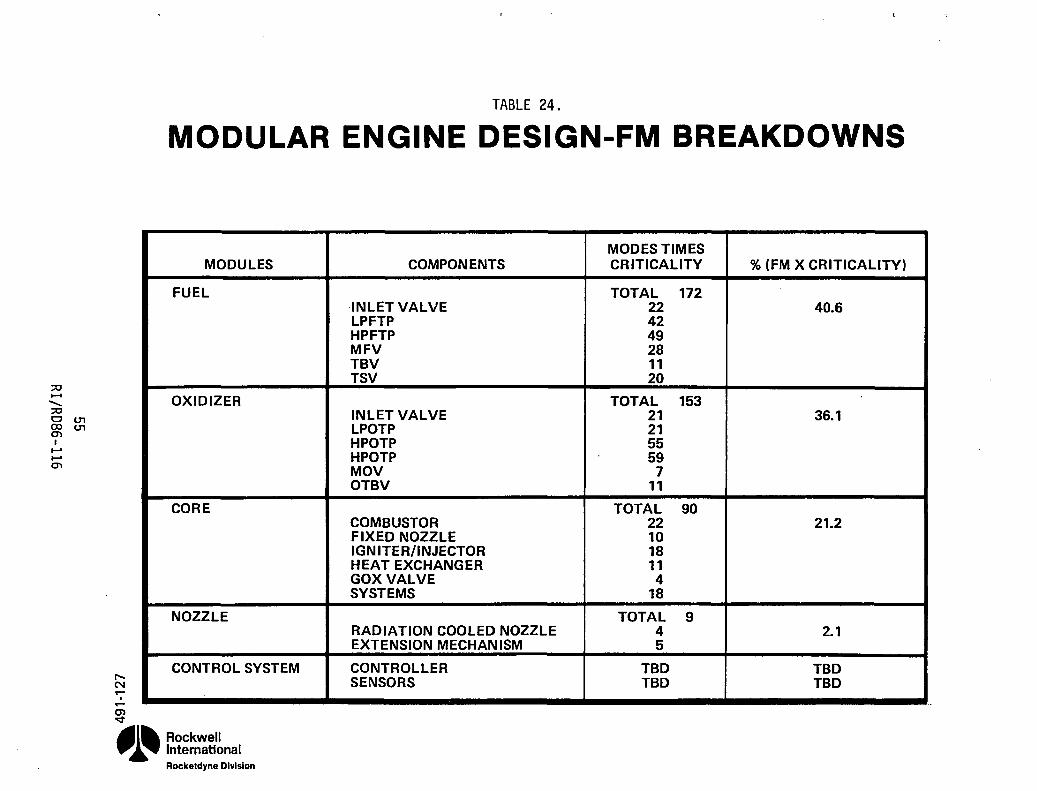
;::0 ...... ........ ;::0 c U1 ex> U1 en I I-' I-' en
TABLE 24.
MODULAR ENGINE DESIGN-FM BREAKDOWNS
r-N ....
o .... m ..;t
MODULES
FUEL
OXIDIZER
CORE
NOZZLE
CONTROL SYSTEM
~l~ Rockwell ".~ International
Rockeldyne Division
COMPONENTS
INLET VALVE LPFTP HPFTP MFV TBV TSV
INLET VALVE LPOTP HPOTP HPOTP MOV OTBV
COMBUSTOR FIXED NOZZLE IGN ITER/INJECTOR HEAT EXCHANGER GOX VALVE SYSTEMS
RADIATION COOLED NOZZLE EXTENSION MECHANISM
CONTROLLER SENSORS
MODES TIMES CRITICALITY % (FM X CRITICALITY)
TOTAL 172 22 40.6 42 49 28 11 20
TOTAL 153 21 36.1 21 55 59 7
11
TOTAL 90 22 21.2 10 18 11 4
18
TOTAL 9 4 2.1 5
TBD TBD TBD TBD

:::0 ...... '-:::0 001 co 0'1 0'1 I ..... .....
0'1
OXIDIZER MODULE
< M ...... (0
riJ co '<t
CONTAINS: OXIDIZER INLET VALVE ~ LOW PRESSURE OXIDIZER TURBOPUMP ~ HIGH PRESSURE OXIDIZER TURBOPUMY,;j/ OXIDIZER i MAIN OXIDIZER VALVE MODULE OXIDIZER TURBINE BYPASS VALVE,I REMOV~~ ICHMSENSORS //......... /' ~~~
/'
I
NOZZLE MODULE /\' CONTAINS: \
RADIATION-COOLED NOZZLE , EXTENSION MECHANISM , ICHM SENSORS '
OXIDIZER INLET
CONTROllER MODULE LOCATION
41~ Rockwell ". ~ International FIGURE 10. MODULAR ENGINE, TOP VIEW
Rockeld,ne Division
FUEL INLET
FUEL MODULE CONTAINS:
FUEL INLET VALVE LOW PRESSURE FUEL TURBOPUMP HIGH PRESSURE FUEL TURBOPUMP MAIN FUEL VALVE TURBINE BYPASS VALVE ICHM SENSORS
of engine start and shutdown characteristics, engine throttling capabilities, and component transient sensitivities including opened-loop control valve sequencing, closed-loop valve controller gain, and valve placements.
Several engine transient simulation runs were made for the baseline'7.5K engine in order to determine proper valve sequencing for stable engine operation and to predict engine dynamic characteristics during start and shutdown. Results indicated that:
1. The engine can be ramped from Tank Head Idle (THI) (engine conditioning and propellant tank settling completed) to Pumped-Idle (PI) mode in approximately 6 seconds without extreme mixture ratio overshoots. The engine operates stably during the transition to PI mode (12 percent of full thrust and 4:1 mixture ratio) and at steady state PI.
2. The engine can be ramped stably from PI mode to 90 percent of full thrust within 5 seconds. Stable engine operation is also achieved at mainstage (*7,500 lb thrust and 6:1 mixture ratio).
3. The engine can be shutdown stably in approximately 0.2 seconds from full thrust. The main fuel and oxidizer pump speeds, however, require 3
seconds to decay due to the inertia of the rotating components.
Table 25 summarizes the time requirements for the 7.5K engine start and shutdown. In the open-loop control valve sequencing employed for transition from THI to mainstage operation, the MOV opens to its PI position in 4 seconds while the MFV and TBV are left fully opened in the THI. Different MOV ramp rates were examined in order to obtain desired mixture ratio variations. Stable PI engine operation at 12 percent full thrust and 4:1 mixture ratio was achieved within 6 seconds from THI. A steady-state mixture ratio of 4:1 was selected for PI in order to avoid flow and instability induced by the low main fuel pump flow coefficients.
57 RI/RDB6-116

TABLE 25. 7.5K ENGINE STARTS AND SHUTDOWN TIME CAPABILITIES
ENGINE OPERATION
ENGINE RAMP THI TO PI: CHAMBER PRESSURE THRUST MIXTURE RATIO
ENGINE RAMP PI TO 90% RATED THRUST: CHAMBER PRESSURE THRUST MIXTURE RATIO
ENGINE SHUTDOWN FROM RATED THRUST: CHAMBER PRESSURE THRUST MIXTURE RATIO MAIN PUMP SPEEDS
\
TIME REQUIREMENTS (SECONDS)
6.0
6.0
6.0
5.0
5.0
5.0
0.2
0.2
0.2
3.0
Details of this study including valve sequencing and engine parameters such as chamber pressure. thrust. mixture ratio and pump speeds are presented in Appendix 5. This transient simulation model has subsequently been modified to include the near term controller for closed-loop control simulation. This additional effort was done under the ICHM subtask E.1/E.2.
5B RIIRDB6-116

-,
Turbine Shutoff Valve. As part of the engine design evolution, the effects of a turbine shutoff valve were determined. The primary function of the turbine shutoff valve (TSV) is to provide rapid turbine flow cutoff for quicker turbomachinery speed decay during engine shutdown to limit the time of operation at the fuel turbopump critical speeds. The TSV may also be necessary to prevent rotation of the turbomachinery during the tank-head idle mode of operation. The two locations being considered for the TSV are shown on the OTV engine schematic presented in Figure 11. The TSV can be located either downstream of the high pressure oxidizer turbine (HPOT) or upstream of the high pressure fuel turbine (HPFT) as indicated on the schematic at locations 8-a and 8-b, respectively.
The engine transient simUlation model described in the previous section was modified to include a TSV. Several engine shutdown transient simUlations from mainstage operation were then made. Results from the model indicate that chamber pressure, thrust, and mixture ratio are cutoff stably within 0.2 seconds from full thrust for the engine with a TSV. The main pump speeds decay to 10 percent of the nominal values within 2 seconds. This same engine without a TSV requires more than 3 seconds for the same reduction in pump speeds. location of the TSV had little effect on the transient shutdown trends in chamber pressure, thrust, mixture ratio, or pump speed decay.
Details of this study are presented in Appendix 6 in which valve sequencing and pertinent engine parameters are illustrated for both .locations of the TSV. The reduced time for pump speed decay could result in increased turbomachinery life and improved engine reliability.
Redundancy
FME mitigation and improvements in reliability are achievable through component redundancy in three areas. Redundant sensors for critical control and health monitoring parameters is one of these areas. Backup sensors not only provide fail operational capability during primary sensor failure, but also provide a means by which erroneous signals may be detected. The enhanced
59 RI/RD86-1l6

H2 --I:xJ--.t LOW PRESSURE
111 I'UMI'
104;< MAIN PUMP
131
" IAI " , RtF " .. -i><J--
121
(AI ~ HYDRAULIC
I TURSI~E r---- -, r - - i><1- _.l.. - --.J
"""'--~ 1'" L.-__ ~
HEAT EXCHANGER
(1) IFV (2) IOV (3) MFV (4) MOV (5) TBV (6) OTBV -(7) GOV (8) TSV
(A)
INLET FUEL VALVE INLET OXIDIZER VALVE MAIN FUEL VALVE MAIN OXIDIZER VALVE TURBINE BYPASS VALVE OXIDIZER TURBINE BYPASS VALVE GASEOUS OXIDIZER VALVE TURBINE SHUTOFF VALVE (LOCATED AT EITHER A OR B) FULL FLOW HYDRAULIC TURBINE FOR LOW PRESSURE LOX PUMP
Figure 11. OTV 7.5K Engine Flow Schematic with Turbine Shutoff Valve
60 RI/RD86-116

sensing capability realized in this manner improves overall engine reliability and also assists in failure effects mitigation by enabling corrective measures to be taken based on accurate information.
These same benefits may be achieved through the use of redundant electrical/optical harnesses. Backup cables for critical sensor and control signals would be routed through different paths. In this manner, damage to one harness caused by a localized incident such as fire or impact would not affect the backup system, thus providing a fail operational result.
The high pressure turbomachinery is another area in which redundancy would improve engine reliability. A reliability and life cycle cost analysis was performed for various engine system configurations involving redundant components. The baseline case to which these systems were compared was a single 15,000 pound thrust engine without any redundant subsystems. The five configurations incorporating varying degrees of redundancy which were analyzed are:
a) Single engine with boost and main pumps standby redundant; b) Single engine with standby redundant main pumps; c) Single engine with capability to switch out failed main pumps; d) Single engine with redundant power head (all components less thrust
chamber); and e) Parallel redundant (2) main engines with a non-independent failure of
3 percent.
A schematic of configuration c with redundant high pressure turbopumps is presented in Figure 12.
In order to evaluate overall engine systems reliability, the failure rate apportionment between major component groups was determined. The estimating procedure was based, primarily, on actual data from the SSME but included other rocket engine data as well. These component reliabilities, failure rates, and apportionments are presented in Table 26.
61 RI/RDB6-1l6

:;:c ....... ........ :;:c om roN m I
...... ...... m
N M ..--, ..--C) ~
REDUNDANT TURBOPUMP FUNCTIONS
• REDUNDANT LPTP AND HPTP V. REDUNDANT HPTP
• LPTP FOR FAILED HPTP
FUEL INJ .. I
~l~ Rockwell ".~ International
FIGURE 12.
Rocketdyne Division

;0 ...... ........ ;0 t::l 0'1 CO W 0'1 I ...... t-' 0'1
TABLE 26.
OTV ENGINE RELIABILITY DATA
COMPONENT
SYSTEMS, LINES, DUCTS
COMBUSTION DEVICES
TURBOMACHINERY
CONTROLS/VALVES
ELECTRICAL AND FLIGHT INSTRUMENTATION
CONTROLLER
(1) Rs = (Rs)n FOR MULTIPLE BURNS
(2) FAILURE RATE FOR 106 HRS
SINGLE START RELIABILITY Rs(1)
0.999964
0.99983
0.99966
0.999938
0.999965
0.999997
0.999354
(3) PERCENTAGE OF FAILURES FOR 12 MIN. BURN
M C") .-, .-0) o::t
41~ Rockwell .,.~ International
Rockeldyne Division
FAILURE RATE, ;>,.(2) APPORTIONMENT %(3) ,
543 9.64
849 22.65
1666 44.87
624 12.46
522 9.30
66 1.08 --4270 100.00
,
I

Overall engine system reliabilities and mean times to failure (MTTF) based upon the component data are summarized in Table 27. The parallel redundant configuration with two main engines achieves the highest reliability and MTTF, followed by a single engine with capability to switch out failed main pumps (operate on boost pumps only). Both configurations of standby pumps achieve modest increases in both reliability and MTTF. However, due to the added complexity, the configuration consisting of a single engine with a redundant power head achieves only a slight gain in reliability over the baseline engine.
These reliabilities were used to calculate the mission cost impact of the various engine configurations. The cost of engine/component redundancy is comprised of mission lost costs and the cost of the extra propellant required due to extra engine weight and reduction in Isp. These calculations were based on 412 missions, a lost mission cost of 184 M$, and a propellant cost of 1500 $/lb. The life cycle costs for the various configurations are presented in Figure 13. The lowest overall cost is that of the baseline 15K single engine but the configuration with the lowest mission lost cost (also safest for return of manned vehicle) is the two 7.SK engine with only one required for mission completion.
ICHM Evolution
The ICHM system is an area which can contribute significantly to FME mitigation and reliability improvement. The key feature of the advanced ICHM which will make these benefits possible is the use of advanced sensors for engine health monitoring. By having a continuous monitor of failure prone components, incipient failures can be detected and corrective actions taken before serious damage might occur. Several of the sensors will also eliminate the need for routine inspections thus streamlining engine maintenance.
Fiberoptic def1ectometers will be used to monitor the condition of ball bearings in the turbomachinery. By optically measuring the deformation of the outer race as each ball passes, bearing wear can be detected much earlier than
64 RI/R086-116

::0 ...... ........ ;0
~ 0"1 I ...... ......
0"1
'<:t M ,
.-(j) '<:t
TABLE 27.
FUNCTION REDUNDANCY-ENGINE AND TURBO.MACHINERY
(MEAN TIME TO FAILURE AND RELIABILITY)
CONFIGURATION MTTF = ~, HR. (2)
SINGLE ENGINE - 15K 233.3 (BASELINE)
SINGLE ENGINE WITH TIP FUNCTION REDUNDANCY
REDUNDANT LPP AND HPP PUMPS (8) 260.2 REDUNDANT HPP PUMPS (6) 257.8 BOOST PUMP FOR FAILED HPP 305.2
REDUNDANT POWERHEAD
TWO-7500 LB ENGINES (3) 349.9 116.6
NOTES: (1) R = R2
n e- At (N = 6, t = 0.5 HR, A = FAILURE RATE)
(2) MTTF = 106
A
(3) ONLY ONE ENGINE REQUIRED TO COMPLETE MISSION
(4) 0.03 NON-INDEPENDENT FAILURE CORRELATION FACTOR
(5) BOTH ENGINES NEEDED FOR MISSION
RELIABI LlTY (SINGLE MISSION)
0.99404
0.99464 0.99455 0.99513
0.99417
0.99987 (4) 0.99189 (5)
~l~ Rockwell ... ~ International
Rftl":lt-.tdvnA niviflinn
FAILURES PER 10,000
I
60
54 55 49
1.3 81

;;0 ...... ........ ;;0 Cl m ~m I ......
...... m
« LO M .... •
1.8
1.4
1.2
1.0 -III !! ~ 0.8 0 (J
0.8
0.4
0.2
0
REDUNDANCY, MISSION COST IMPACT $1500/LB. PROP., 412 MISSIONS·
1 ENG. BOOST PUMP (2) BACKUP
REDUNDANT MAIN PUMPS
REDUNDANCY OPTIONS
c:::J PROPELLANT COST DELTAS
VZl2I MISSION LOST COST
·"""IIII~
2 ENG. 1 ENG. REDUNDANT POWERHEAD
~ (1) 34 MANNED MISSIONS, MARTIN MARIETTA EXCHANGE FACTORS
,~, (2) EXTRA FUEL USED ONLY IN THE 34 MANNED MISSIONS
Rockwell International FIGURE 13. Rockeldyne Division

with accelerometers. This early detection provides a safety margin during which the controller can respond by engine throttling or shutdown. In this manner, major turbomachinery damage which could propagate to adjoining systems would be avoided. Use of fiberoptic deflectometers will also prevent false signals from spurious vibrations which would be picked up by accelerometers and would obviate routine visual inspections requiring disassembly.
Turbine blade condition may be monitored with fiberoptic pyrometers. By optically measuring the infra red radiation eminating from each blade, real time temperatures can be directly monitored. With their inherently fast response these sensors will be able to detect damaging over temps and excessive transient excursions quickly enough to allow corrective measures to be taken by the engine controller. In addition, fiberoptic pyrometers will eliminate the need for costly disassembly and visual inspection to assess turbine blade conditions.
Another advanced sensor to be included in the ICHM system is the isotope wear detector. In this approach the wear surfaces of critical components are doped with low level radioactive isotopes. As the surfaces wear the emissions are reduced. Thus, by externally monitoring the emissions with a Gieger-counter type sensor, the status of those components can be determined without disassembly and inspection. Hardware to be monitored by these sensors include ball bearings, valve seats, turbine blades, and the injector face. Isotopic wear detectors may be mounted on the engines for inflight sensing or more likely, used in preflight check outs in the space station bay.
Torquemeters will be used on turbopump shafts to detect bearing wear, seal rub, and blade/impell~r to housing rub. The current method for detecting rub is done manually, postflight, with a hand held unit requiring the opening of access ports. By installing magnetic strips on the turbopump shafts, sensors can provide continuous real time measurements of the torques during engine operation. Early detection of rubbing and incipient turbopump failures will enable controller initiated responses to prevent further damage.
67 RI/RDB6-1l6

Similar sensors will be used to measure turbopump shaft speeds. Shafts will incorporate colored striping and optical tachometers for measurement. These sensors may help to prevent the over spinning of the turbopumps.
An additional advanced sensor being considered for the ICHM is a spectrometer for exhaust gas analyses. Engine mixture ratio may be determined from the chemical composition of the exhaust gas in addition to component wear/failure as evidenced by traces of metal species.
A summary of the advanced sensors to be used in ICHM systems is presented in Table 28. Their location scan be identified on the engine schematic provided in Figure 14.
In order to take full advantage of the advanced sensors, the ICHM system must ut111ze a controller commensurate w1th the1r capab111ties. It must have the memory capacity to store the additional sensory data and the computational ab111ty to analyze and interpret that information. The logic programmed into the controller software will be a key element in FME mitigation and engine reliabjlity improvement. Based on numerous 1nput data from the advanced sensors, 1n addition to the standard instrumentation, the controller will continuously monitor the health of critical components while performing the normal functions of thrust and mixture ratio control. In the event of a failure or incipient failure as predicted through advanced sensor input analyses, the controller will direct corrective measures to prevent or m1nimize hardware damage. A few of the possible corrective actions would be a simple warning to the crew, off-design operation at reduced thrust level and/or mixture ratio, or a full engine shutdown. The decision as to what actions will be taken w1l1 be based not only on sensor data but mission status as well; i.e., the corrective actions taken during the early phases of a mission might be different from those taken after payload deployment during OTV return. Health monitoring data will also be used to determine when maintenance is required. Thus, the ICHM will allow an efficient maintenance plan based on servicing done on a "as needed" basis.
68 RI/RD8&-11&

ADVANCED TECHNOLOGY
FIBEROPTIC DEFL[CTOMETE~
FlBEROPTIC PYROMETER
ISOTOPE WEAR DETECTOI1
TORQUEMETER
OPTICAL TACHOMETER
SPECTROMETER
TABLE 28. ADVANCED ICH" SENSORS
MONITORED COMPONENTS
BALL BEARING
TURBINE BLADES
BALL BEARINGS VALVE SEATS INJECTOR FACF. TURBINE BLADES
TURBOPUMP ROTATING COMPONENTS
TURBOPUMP SHAFTS
EXHAUST GAS CHEMICAL COMPOSITION
DESCRIPTION OF OPERATION
BALL PASS FRFQ. AND AMPlITUDE
MEASURED by DEFOR-MATION OF OUTER RACE AS EACH BALL PASSES
IR RADIATION, ASSO-CIATED TO TEMPERATURE, MEASURED FOR EACH BLADE
WEAR SURFACE IS ISO-TOPED AT VERY LOW LEVEL, SO AS IT WEARS, THE EMISSTONS ARE REDUCED
MAGNETIC STRIPES ON TURBOPUMP SHAFTS SENSOR MEASURES ROTATIONAL RESISTANCE STRIPES ON SHAFT, OPTICAL SENSOR
SPECTROGRAPHIC SENSOR AND WAVE FORM ANALYZER FOR M.R. MEASUREMENT & METAllH~ C;PI=ClI=S
69 RIIRD86-116
EXISTING MONITOR
ACCELEROMETERS
VISUAL INSPECTION
VISUAL INSPECTION
GAS TEMPERATURE MONITOR
ACCELEROMETERS
VISUALINSPFCTION
MANUAL MEASUREMENT
VARIABLE RELUCTANCE MEASUREMENT NONE
BENEFITS OF ADVANCED MONITOR
DIRECT MONITOR OF BEARING
NO FALSE SIGNALS FROM SPURIOUS VIBRATION
REAL TIME MONITOR NO DISASSEMBLY REAL TIME MONITOR NO DISASSEMBLY DIRECT MONITOR OF
AFFECTED PART FAST RESPONSE NON-INTRUSIVE NO FALSE SIGNALS
FROM SPURIOUS VIBRATIONS
POSSIBLE REAL TIME MONITOR
DIRECT MONITORING OF MATERIAL LOSS
REAL TIME MONITOR NO DISASSEMBLY
LESS COMPLEX
MEASURE M.R. AND METALLIC SPECIES FOR FAILURE DETECTION

;t:I ..... ........ ;t:I CJ ex> 0'\
• ..... ..... 0'\
...... a
Q) M .... , ....
~l'
MODULAR ClV ENGINE WITH ADVANCED INSTRUMENTATION SCHEMATIC
FUEL INLET PNEU. INLET ®,
,..I I I I I I I IINL
-r~----r-----~--·~~~~~~~~~:~-f=~Ji~~~:=:=~::. ~-=l--:;r .1 --,- .• ~ 'U I • I C.( •· .. tJfl
~{J-,."",
~D_U§!J I I I I I I I I I I I I I 1----I I I I I I I I I I I I I I
I
• I I 1..-
FUEl TANK PRESS.
Rockwell International Rocketdyne Division
-@>
. .q
rl--F~I Iii i r········ .. ···.i
I I I
®' ®
'@) ''''~
OXIDIZER MODULE
@ L _______ ~--------,------------------,
® ., ..<.ffiX!!)
CORE MODULE
~ @.X!D, .bi~ I-l-~
@X!!D
CONTROLLER MODULE
-------T"---------o-----------------J------------------ .: I I I LI I
: ~ NOZZLE MODULE : I I OXID. TANK
PRESS . L _____________________________________________________ J
FIGURE 14.
LEGEND
lHTP • lOW 1'11(_' FUlL _IMUII'
"FTP • NIIIM PIIUSUII[ FUlL _IO'UII'
l'OTP • LOW PIIlSSUIt, OllOlna ruttl_'
"OTP • NUIH PIIllSUltt Ol,Dlna TUIII_'
ory • 11Il" Fun VAlVl 'OV • IHUT DIIDIZU VAlVl IIFV • IIAIN FUll VAlVE IIOY • IIAI. OI'Dln" VALVE TlY • _I,ll( I"'A" VALVI OTIV • OIIDIZU TUIII'Nt
.... ss VALW; IIOV • eAstOUS OllOlnl VALVE TSV • TUllIIN[ SHUTOFF VAL VI I!lFV • I8NIT[1 FUll VALVE 100V • 'ONI"I OllOlnl
VALVI lOI NU • l:::'~D '~~:!'~I . I[QtN • III'OIIOfI[N I[ Cl[NUATOI 'CA' 'NlUl!ATlC CONnoo.
.sstlllU
stNSOII COOtS : , . ,,,-, T • "1I'UAT\IIIt •• FlO.A" S • SHArr SPUD A • ACCllIIIA"ON I • IGNlrU ., .. a l • '051T10II .. V • VAL VI POIITION I • IUIiNe CONDITION a • TUlI,N[ IUO[ CONDITION F • FA"_ N • rDlOUl O. I["'HI ... II • OA' "'CIU

Servicing
Efforts completed in FME mitigation and reliability improvement through servicing w1ll be covered in the following section under the heading of Maintainability Studies.
71 RI/RD86-116

MAINTAINABILITY STUDIES & PLAN
The space-based operations and reusability goals for this engine will require novel and advanced maintenance techniques to be employed. To be truly effective, these servicing features must be incorporated at an early stage of engine development. Even though it is likely that this capability will not be utilized at initial deployment, consideration of space maintainability will permit smooth evolution to full space-based operations. One of the goals of the maintenance study was to determine the viability of engine space maintenance and configurations which maximize its overall benefit.
As currently envisioned, OTV servicing will be performed in a maintenance facility which is part of the Space Station. Although partially enclosed for debris protection, this facility will be a vacuum environment. Appropriate tools, parts storage, lighting, and spares will be contained in the servicing bay. Work will be performed by teleoperated or automated servicing devices and/or by EVA astronauts. Manipulator arms will transport tools, parts, and astronauts as needed.
An initial engine maintenance ph1losophy centering on a modular engine packaging design was adopted as a baseline approach. Should a component fail, the module containing it can be replaced without removing the engine from the vehicle. Once off the engine the module can be returned to earth (or brought into the space station) for repair with lower handling and transportation penalties than if an entire engine assembly was involved. In addition, once off the engine, access to the components in a module is eased. A lesser volume and weight of on-orbit spares is required because a complete engine is not needed for each failure encountered. Drawbacks to modular maintenance include possible long work times involved because modules may have more interface connections and may require more post-maintenance checkouts, additional logistical effort needed to coordinate the greater number of deliverable assemblies, and the additional weight resulting from the use of space-operable couplings.
12 RI/RD86-116

. ~ .
Besides the inclusion of modular maintenance capability, the initial philosophy is to provide a large amount of automation into engine maintainability. The goal is to minimize astronaut EVA effort required. Especially for relatively frequent inspections, servicing, and checkouts, automated equipment and remote manipulators should be capable of completing the tasks. EVA astronauts will be required as backup for failures in the remote equipment and for unusual tasks which are not automated.
An evaluation of this maintenance philosophy of performing removal and replacement (R&R) of components or component groups (modules) was made. This was done by comparing engine assembly versus module versus component R&R cost implications. In addition, ground versus space R&R of an engine component was compared. Although it must be noted that this assessment is first-order and applicable to one specific engine configuration, the cost differences are significant and should not be radically altered for similar designs.
The engine assembly versus module versus component R&R evaluation compared the cost of performing each operation in space with the cost of transporting the needed replacement part to the space station. Three specific cases were used, derived from the baseline 1.5K engine design:
1) Component - Fuel turbopump consisting of the T-mounted low pressure and high pressure fuel turbopumps.
2) Module - Fuel module consisting of the low and high pressure fuel turbopumps, main fuel valve, inlet fuel valve, and turbine bypass valve.
3) Engine Assembly - The entire engine assembly.
13 RI/RD86-116

Timelines detailing R&R tasks were developed to determine the work times for each case. It was assumed that maintenance is to be accomplished at a space station servicing facility (vacuum environment) containing: (1) work platforms to support EVA astronauts or servicing robots, (2) a parts storage area with remote storage capability, (3) required tools and a tool storage area with remote stowage capability, (4) test and checkout equipment with remote stowage capability, (5) teleoperated manipulator(s) to translate tools, parts, and checkout equipment between storage and the work station, and (6) sufficient electrical, pneumatics and illumination to support the task.
The engine design features required to perform the required maintenance were: guides for self-alignment of mating parts, fluid interfaces which permit tools to remotely mate and demate, electrical interfaces which mate and demate simultaneously with the fluid interfaces, and an Integrated Control and Health Monitoring (ICHM) system which provides a complete assessment of engine health without the need for routine inspections.
It was also assumed that a three-person crew is to be used for EVA, namely (1) one EVA astronaut who actually performs the work, (2) one astronaut as an EVA backup and task coordinator, and (3) one astronaut inside the station to operate remote equipment.
other assumptions made included: a 1990 technology level, EVA preparation times were not to be included, and the EVA astronaut is allowed ten minutes of rest per active work hour, but is considered at rest during remote operations.
The resulting timelines are depicted in Figures 15, 16, and 17. It should be noted that although these times were subjectively determined, they were influenced by space task time studies and the ground task times currently encountered with the Space Shuttle Main Engine.
74 RI/RD86-1l6

:;:0 ...... -:;:0 o --.J (X) (J"I en I --en
Lt) o '<:t m CX) '<:t
OTV ENGINE FUEL TURBOPUMP REMOVAL/INST ALLATION/CHECKOUT TIMELINE
I --- ELAPSED TIME (MINUTES) I o 60 120 180 240 300 360 420 480 540 600 • iii iii' iii' iii ii' iii ii' iii , ii' iii iii i i
. TRANSLATE PERSONNEL AND EQUIPMENT TO OTV ENGINE AREA
I I. I I I POSITION OTV AND MATE RMS TO TURBOPUMP
NOTE:
I I I INSTALL INTERFACE INSTALL/REMOVE TOOLS (4 JOINTS)
I I I I I • INITIATE INTERFACE DISCONNECT AND REMOVE TURBOPUMP
I I I I I _ REMOVE INTERFACE INSTALL/REMOVE TOOLS AND RETAIN AT OTV
I I I I I I • TRANSLATE TURBOPUMP INTO STORAGE AND DEMATE RMS
• I I I I
MATE RMS TO TURBOPUMP THEN REMOVE TURBOPUMP FROM STORAGE AND TRANSLATE TO OTV ENGINE AREA
• I I I I
•••• INSTALL INTERFACE INSTALL/REMOVE TOOLS (4 JOINTS) I I I •
• POSITION TURBOPUMP ON ENGINE GUIDE RAIL AND INITIATE INTERFACE CONNECT THEN DEMATE RMS
I I I I _ REMOVE INTERFACE INSTALL/REMOVE TOOLS
I I I CONNECT CHECKOUT EQUIPMENT TO ENGINE
I I I PERFORM REMOTE ELECTRICAL INTERFACE CHECKOUT
I I I I I _ PERFORM REMOTE LEAK CHECK OF TURBOPUMP FLUID JOINTS
I I I I _ REMOVE CHECKOUT EQUIPMENT I I
REST PERIODS DURING PASSIVE EVA OPERATIONS SHOWN AS 0
TRANSLATE PERSONNEL AND EQUIPMENT TO STORAGE AREA
... ELAPSED TIME 5 HOURS 5 MINUTES
~l~ Rockwell .,.~ International
Rocketdyne Division FIGURE 15.

:;:c .......
......... :;:c C -...J. 00 0"1, 0"1 I
...... ...... 0"1
co CO M m CO "It
OTV ENGINE FUEL MODULE REMOV AL/INST ALLATION/CHECKOU T TI MELINE
.- n ------ ELAPSED TIME (MINUTES) I o 60 120 180. 240 300 360 420 480 540 600 • , , , iiI , " 'i iii' i , , iii' iii ii' , , , , iii i •
EVA REST PERIODS (SEE NOTE)
TRANSLATE PERSONNEL AND EQUIPMENTTO OTV ENGINE AREA
I I I I I POSITION OTV AND MATERMS TO FUEL MODULE L- I I I ••• ,.... INSTALL INTERFACE INSTALL/REMOVE TOOLS (6 JOINTS)
I I I I I • INITIATE INTERFACE DISCONNECT AND REMOVE FUEL MODULE
..
I I I I I REMOVE INTERFACE INSTALL/REMOVE TOOLS AND RETAIN AT OTV
I I I I I • TR~NSLATE FU~L MODULE ,INTO STOR~GE AND DE~ATE RMS
• MATE RMS TO FUEL MODULE THEN REMOVE FUEL MODULE FROM STORAGE AND TRANSLATE TO OTV ENGINE AREA
I I I
INSTALL INTERFACE INSTALL/REMOVE TOOLS (6 JOINTS) I I I I
POSITION FUEL MODULE ON ENGINE GUIDE RAIL AND INITIATE INTERFACE CONNECT THEN DEMATE RMS
I I I I
••• REMOVE INTERFACE INSTALL/REMOVE TOOLS l... I I I ~ CONNECT CHECKOUT EQUIPMENT TO ENGINE
PERFORM REMOTE ELECTRICAL INTERFACE CHECKOUT. I I I I
PERFORM REMOTE LEAK CHECK OF FUEL MODULE
I NOTE:
REMOVE CHECKOUT EQUIPMENT AND SECURE
I I
REST PERIODS DURING PASSIVE EVA OPERATIONS SHOWN AS 0
• TRANSLATE PERSONNEL AND EQUIPMENT TO STORAGE AREA
I I
• ELAPSED TIME 6 HOURS 30 MINUTES
.41~ Rockwell ".~ International
Rocketdyne Division FIGURE 16.

;:0 ...... ";:0 o ......... CO ......... m I I-' I-' m
en 00 M c;j, 00 ~
OTV ENGINE ASSEMBLY REMOVAL/INSTALLATION/CHECKOUT TIMELINE
I ELAPSED TIME (MINUTES) ~ o 60 120 180 240 300 360 420 480 540 600 • iii , i , 'i ii' iii ii' iii ii' 'i i' ii' i 'ii' ii'
I
TRANSLATE PERSONNEL AND EQUIPMENT TO OTV ENGINE AREA
POSlTloJ OTV AND ~ATE RMS T~ ENGINE I I
NOTE:
INSTALL INTERFACE INSTALL/REMOVE TOOLS (4 JOINTS) I I I I I
_INITIATE INTERFACE DISCONNECT AND REMOVE ENGINE I I I I I
_ REMOVE INTERFACE INSTALL/REMOVE TOOLS AND RETAIN AT OTV I I I I I
• TRANSLATE ENGINE INTO STORAGE AND DEMATE RMS I I I I
MATE RMS TO ENGINE THEN REMOVE ENGINE FROM STORAGE AND TRANSLATE TO OTV ENGINE AREA
I I I . I •••• INSTALL INTERFACE INSTALL/REMOVE TOOLS (4 JOINTS)
• I I I I
• POSITION ENGINE ON ENGINE GUIDE RAIL AND INITIATE INTERFACE CONNECT THEN DEMATE RMS FROM ENGINE
_ REMOVE INTERFACE INSTALL/REMOVE TOOLS I I I I I . I I I
CONNECT ENGINE CHECKOUT EQUIPMENT TO ENGINE I I I I
PERFORM REMOTE ELECTRICAL INTERFACE CHECKOUT I I I I I
_ PERFORM REMOTE LEAK CHECK OF ENGINE INTERFACE JOINTS I I I
_ REMOVE CHECKOUT EQUIPMENT I I
TRANSLATE PERSONNEL AND REST PERIODS DURING PASSIVE EVA OPERATIONS SHOWN AS 0
EQUIPMENT TO STORAGE AREA I
ELAPSED TIME 5 HOURS 5 MINUTES
~l~ Rockwell ... ~ International
Rockeldyne Division FIGURE 17.

A cost of $118,000 per hour was applied to these maintenance tasks. This cost includes the three person astronaut crew for EVA operations, EVA preparation, and ground support. A concensus of several space station studies was the basis of this figure. Because of the great similarity between tasks, skills, and equipment required for the three cases, development, facility, and training costs were assumed to be equal.
Transportation costs were established based on space shuttle cargo costs for the particular part replaced in each case. In other words, for module R&R, the cost of transportation was determined from the size and weight of the module; for engine R&R, the cost was based on the size and weight of the engine assembly. The cost figures used were the greater of $1,631 per pound, or $10,712 per cubic foot volume.
Table 29 details the cost comparison. For each case, weight and volume of the replaced unit is given, with the STS charges applied to determine which fee to use. It can be seen that the transportation costs of the component and module cases are based on weight, but for the engine, it is based on volume and is a considerably higher amount. The EVA task costs, based on the timelines, are then added to determine total R&R costs. Whereas the difference between component and module R&R is relatively small, and hence could be affected by other factors not considered in this first-order analysis, both are much less costly than engine R&R. This shows a clear advantage to sub-engine assembly (either component or module) R&R capability.
To examine the consequences of performing R&R tasks at a ground facility, a timeline was prepared for the case of removing a component after R&R in space and return to earth of an engine assembly. The T-mounted fuel low and high pressure turbopump was selected as the component to permit comparison with the previous timelines. The analysis assumes the task is performed by a crew of two with the engine mounted on an engine handler. The assumptions regarding the engine design remain the same. The timeline is shown in Figure 6-4.
78 RI/RD86-116
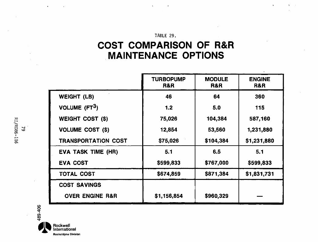
;;0 ..... ........ ;;0 Cl ....... 00 1.0 m I ...... ...... m
TABLE 29.
COST COMPARISON OF R&R MAINTENANCE OPTIONS
co Cl ~
I
en co ~
WEIGHT (LB)
VOLUME (FT3)
WEIGHT COST ($)
VOLUME COST ($)
TRANSPORTATION COST
EVA TASK TIME (HR)
EVA COST
TOTAL COST
COST SAVINGS
OVER ENGINE R&R
~l~ Rockwell p.~ International
Rocketdyne Division
TURBO PUMP MODULE R&R R&R
46 64
1.2 5.0
75,026 104,384
12,854 53,560
$75,026 $104,384
5.1 6.5
$599,833 $767,000
$674,859 $871,384
$1,156,854 $960,329
ENGINE R&R
360
115
587,160
1,231,880
$1,231,880
5.1
$599,833
$1,831,731
-

:::0 ...... ........ :::0 cOO 000 0'\ I
...... ...... 0'\
o ~ dl
OTV ENGINE FUEL TURBOPUMP REMOVAL/INSTALLATION/CHECKOUT TIMELINE
(ON GROUND) r· ------- ELAPSED TIME (MINUTES)
o 60 120 180 240 300 360 420 480 540 600 Iii I Iii iii i I I I I I I I I I I I I I I I I I I I I I I I I i I
POSITION ENGINE AND INSTALL INTERFACE INSTALL/REMOVE TOOLS (4 JOI NTS)
I I I I I • SUPPORT TURBOPUMP/INITIATE INTERFACE DISCONNECT
AND REMOVE TURBOPUMP I I I I
• REMOVE INTERFACE INSTALL/REMOVE TOOLS (4 JOINTS) AND PLACE TURBOPUMP IN CONTAINER
I I I I
,
REMOVE TURBOPUMP FROM CONTAINER AND INSTALL INTERFACE INSTALL/REMOVE TOOLS (4 JOI NTS)
. I I I • POSITION TURBOPUMP ON ENGINE TURBOPUMP . GUIDE RAIL AND INITIATE INTERFACE CONNECT iii I
• REMOVE INTERFACE INSTALL/REMOVE TOOLS (4 JOINTS)
I I I I • CONNECT CHECKOUT EQUIPMENT TO ENGINE
I I I I· I • PERFORM REMOTE ELECTRICAL INTERFACE CHECKOUT
I I I I _ PERFORM REMOTE LEAK CHECK OF
TURBOPUMP FLUID JOINTS I I I
• REMOVE CHECKOUT EQUIPMENT AND SECURE ENGINE CHECKOUT PORTS
I I I • ELAPSED TIME 2 HOURS 20 MINUTES
~' I ,
.... l~ Rockwell
.,.~ International Rockeldyne Division FIGURE 18.

The cost associated with the ground task time is $100 per manhour, or, with a two-person crew, $200 per task hour. This is added to the cost of R&R and transport of the engine (from the previous analysis) to determine the total cost of ground maintenance.
The cost of space R&R of the turbopump is taken from the earlier analysis for comparison. This. is shown in Table 30. It can be seen that the cost of ground tasks are trivial in light of EVA costs, even if it were to be much more extensive. However, EVA R&R is still required to return the engine to earth and the cost of transporting the engine back to the space station is very high. In-space R&R is therefore more economical for maintenance of a problem limited to one component (or module). Situations may arise (i.e., when several components are simultaneously approaching their predicted life limits) when ground R&R may be less costly, but with the capability for sub-engine space maintenance, this evaluation has shown that significant savings are possible for typical contingency maintenance needs.
A detailed list of engine maintenance requirements, based on the Space Shuttle Main Engine (SSME) needs, was defined for the engine life cycle under Task E.1. These 1983 state-of-the-art requirements were reviewed to determine applicability to the orv engine design, as it differs significantly with the SSME. For example, the orv expander cycle has no preburners and hence no requirement for their maintenance. There are other OTV engine maintenance requirements which can be eliminated by incorporating design changes, with respect to similar SSME components, based on different operating conditions and experience gained. For instance, with the drive fluid being a relatively cool hydrogen gas, rather than hot combustion gas as used with the SSME, some inspections can be simplified or reduced in frequency.
81 RI/R086-116

:;0 ....... ....... :;0 o co co N m I ..... ..... m
N o:t .... , .... C) o:t
TABLE 30
GROUND VS SPACE R&R MAINTENANCE TIME AND COST
GROUND R&R SPACE R&R
UNIT ENGINE TURBOPUMP TRANSPORTATION
COST $1,231,880 $75,026
TIME 5.1 hrs 5.1 hrs EVA
COST $599,833 $599,833 TASK-------------------o-------------------
. TIME 2.3 hrs 0 GROUND
COST $467 0
• TOTAL COST $1,832,180 $674,859
~l~ Rockwell p.~ International
Rocketd,.ne Division

By examining where advanced 1990 sensor and data analysis technologies can be used to reduce space maintenance, the instrumentation areas which are most beneficial (from a maintenance viewpoint) can be defined. So, using the 1983 state-of-the-art maintenance requirements as a basis, advanced technologies were identified which would either obviate or simplify each of the routine inspection needs. These advanced instrumentation areas, listed in Table 31, also provide other benefits to the engine, such as improved control and reduced life cycle costs.
A maintenance plan is being developed for the space-based and space-maintained advanced OTV engine. The plan encompasses definition of maintenance requirements, maintenance functions, and maintenance benefits. Its development has been started during this phase of the program (FY ' 85) and will continue during the follow-on phase (FY '86). Requirements, functions and benefits are further outlined in Figure 19.
Requirements
Requirements are used in a general sense. It encompasses engine requirements as well as component requirements. The starting point for these requirements is the vehicle and the mission. Included in these requirements affecting the maintenance plan are engine and component life, as required by the number of missions desired before maintenance actions are undertaken; engine and component reliability as required by vehicle reliability goals; and crew-safety requirements. The approach for each is discussed below.
Component life. As part of the maintenance plan, component life will be established. At this point in time, the calculated life is known for the key engine components from simple one-dimensional analyses. The approach has been to design the components for the desired near-term goal of 300 cycles and 10 hours of operating time before overhaul. The near-term 15K engine was designed
83 RI/R086-116

TABLE 31.
CONTROL AND HEALTH MONITORING INSTRUMENTATION
PARAMETER
FLOWRATE
IGNITER SPARK
VALVE POSITION
ACCELERATION
PRESSURE
TEMPERATURE
SHAFT SPEED
BEARING WEAR
BEARING CONDITION
PUMP TORQUE
LEAKS
MIXTURE RATIO
NOZZLE POSITION
NEAR TERM SENSOR
TURBINE
VOLTAGE, CURRENT
LVDT
ACCELEROMETER
STRAIN GAGE DIAPHRAGM
THERMOCOUPLE,RTD
VARIABLE RELUCTANCE
ISOTOPE DETECTOR
FIBEROPTIC DEFLECTOMETER
TORQUE W~ENCH (BETWEEN MISSION)
MASS SPECTROMETER (BETWEEN MISSION)
TURBINE FLOWMETER
OPTICAL DETECTOR
84 RI/RD86-116
FAR TERM SENSOR
ULTRASONIC
FIBEROPTIC PHOTOMETER
FIBEROPTIC POSITION
ACCELEROMETER
FIBEROPTIC DIAPHRAGM
ULTRASONIC
VARIABLE MAGNETIC
ISOTOPE· DETECTOR
FIBEROPTIC DEFLECTOMETER
MINIATURE TORQUEMETER
PULSED HOLOGRAPHIC (BETWEEN MISSION)
SPECTROMETRIC SPECIES
OPTICAL DETECTOR

;;0 • ...... ...... ;;0 • Cleo eo {jJ • . C'I I ...... ...... •
C'I
REQU I REMENTS I
LIFE (COMPONENT & ENGINE) • RELIABILITY • CREW SAFETY • INTEGRATED CONTROL & •
MONITORING • •
ENGINE MAINTENANCE PLAN
OUTLINE
I FUNCT! ONS AND ACT! ONS I
ENGINE REPLACEMENT ENGINE SERVICE LIMITED COMPONENT REPLACEMENT MODULE REPLACEMENT MAINTENANCE STATUS MONITORING REDLINES
FIGURE 19. MAINTENANCE PLAN OUTLINE
'.,
I RESULTING BENEFITS
• RELIABILITY GAINS .. CREW SAFETY GAINS • LIFE CYCLE COST GAINS

with this approach in mind. A point-design has been obtained (NAS8-33568) for that engine with component life based on simplified analysis anchored on a baseline finite element analysis for the thrust chamber and on simplified analysis for the turbopump bearings and seals. life for the components analyzed is indicated in Table 32 As indicated in the table, some component lives are yet to be determined.
For the current 7.SK engine concept, component life goals are far-term values of 500 cycles and 20 hr. before overhaul. No baseline detail analysis exists on which to base the simplified life analysis for this latter thrust level.
life and Reliability - Relationship. Reliability is a function of component service time at rated condition and number of starts and shutdown cycles. Each mission requires a number of starts and shutdowns and a certain length of time at rated conditions. The true engine life is established by the number of missions at which the engine reliability drops below the desired value from mission considerations.
The true life of a component is not known until sufficient testing has been performed and a statistical average value has been established. A maintenance schedule based on true life is the most cost effective. In the absence of true life values, calculated life is used for each component to determine maintenance frequency and component reliability. Because of the conservative nature of the analytical methods, component calculated life is believed to be many times lower than true life. It is one of the objectives of the maintenance plans to define actions required to (1) base component maintenance on cause (true life) rather than on routine schedule (calculated life), and (2) extend component life through changes in the operating environment.
life Extension. Component life can be extended through the use of a Health Monitoring System which by monitoring certain parameters, keeps track of and forecasts true life and can take actions to operate the component in a less demanding life-extending mode through adaptive control.
86 RI/RD86-116
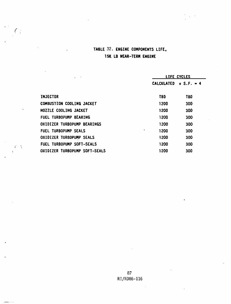
(.
I, ,
TABLE 32. ENGINE COMPONENTS LIFE, 15K LB NEAR-TERM ENGINE
LIFE CYCLES
INJECTOR COMBUSTION COOLING JACKET NOZZLE COOLING JACKET FUEL TURBO PUMP BEARING OXIDIZER TURBOPUMP BEARINGS FUEL TURBO PUMP SEALS OXIDIZER TURBOPUMP SEALS FUEL TURBOPUMP SOFT-SEALS OXIDIZER TURBOPUMP SOFT-SEALS
87 RI/RD86-116
CALCULATED + S.F. a: 4
TBD TBD 1200 300 1200 300 1200 300
1200 300 1200 300 1200 300 1200 300 1200 300

Mean Time t~ Failure. Random variation of component life in a statistical sample is caused by variation of life affecting factors not known or not easily characterized. The mean value of the remaining life is known as the mean-time-to-failure (MTTF). The MTTF can be used in calculating reliability and can be updated and improved as the statistical sample increases. A health monitoring system can provide the function of updating the MTTF.
Failure Rates. Failure rate (A) is the inverse of the MTTF which has the units of time in hours (hr). The units of ~ are l/hr. As MTTF, ~ is a statistical quantity and is used in reliability studies.
R~liability Requirements. The overall reliability of each component is defined as the product of start reliability (Rs) and the mainstage reliability (Rm) for one operational cycle. When "n" number of cycles is involved, the overall reliability is defined as:
n R = Rs Rm
Using the failure rates associated with mainstage (~m) conditions, component reliability can be defined as:
-~ t R = R n e m
s
Engine Reliability. The reliability of the engine is the product of "k" number of component reliabilities so that:
k -A t ~ ~
RENG =// i=l Rn
e
where)9Drepresents the product of component reliabilities from i=l to k. The engine reliability RENG is thus a measure of all component mean-time-tofailure values and represents in one parameter the readiness of the engine to perform the next mission. Because of the "adaptive control" features of the
B8 RI/R086-116

ICHM system and its monitoring capabilities, engine reliability can be changed
by the ICHH. Also the predicted life can be extended by the ICHH by reducing dependency on Safety Factors used in calculations, since MTTF is measured and monitored i~ and between flights.
Redundancy and Crew Safety. Redundancy is also an engine feature used to influence engine HTTF through switching from a component near to failure to a fresh or redundant component. In the same manner, the engine system overall reliability is influenced through use of redundant engines. Redundant engine reliability for two engines (RRENG) is defined as:
2 RR ENG = R + 2R (l-R) (without non-independent failure R)
Reliability Requirements. The budgeted reliability for the engine comes from knowing the minimum reliability desired for the vehicle for (1) mission accomplishment, and (2) crew safe return. Two values of reliability are thus required. For the ICHH to control engine actions, it needs to know the budgeted engine reliability to achieve vehicle required mission reliability and crew-safety reliability.
ICHM Requirements. ICHM requirements for extending engine life and reliability are discussed in this section.
Function Allocation and Logic Diagram. A preliminary first level function allocation and logic diagram for the ICHH is shown in Figure 20. It consists of a control system block, a trend analysis function block, and an on-line monitor function block. Sensors in the control system provide data for the trend analysis function system where MTTF is determined with historical statistical data banks from engine testing and previously accomplished missions. MTTF forecasting is used to (1) continue with the next mission with no other action, (2) to determine post-mission maintenance actions, or (3) exercise adaptive control for remainder of mission. For the latter, the on-line monitor system is exercised and component parameter modification is calculated and effected through the control system.
89 RI/RD86-116

;:c ...... ........ ;:c 01..0 000 0'\ I ...... ......
0'\
TYPICAL TREND ANALYSIS FUNCTIDN (FOR LIFE INDICATING SENSORS)
r STATISTICAL TEST DATA ~
r- NOMINAL & BEYOND TIME TO DURING PARAMETER MODIFICATION RANGE ~ NEXT MISSION FAILURE THIS TO AVOID FAILURE DURING THIS MISSION
NEXT MIISSION OR MISSION
INO ACTION I BEYOND NEXT MISiION BUT ABNORMAL
I POST-MISSION MAINTENANCE REQUIREMENTS J ON-LINE MONITOR FUNCTION
I MINIMUM PARAMETER MODIFICATIDN J t
I PREDICTED CONTROL SETTINGS & OPERATING CONDITIONS I
t ( OTHER COMPONENTS COMPATIBLE PERFORMANCE , WITH NEW OPERATING CONDITIONS? Y OF SYSTEM OK Y
Nt IN t
( ALL ALTERNATE CONTROL SETTINGS TRIED? J fN Y
I ALTERNATE CONTROL SETTINGS I
I NEW MODIFICATION I ( ALL PARAMETER MODIFICATIONS TRIED? J ·MISSION OF PARAMETER 11'1 Yt
ALTERNATIVES
I SORRY' 1 FIGURE 20. ICHM FUNCTION ALLOCATIONS AND LOGIC DIAGRAM
CONTROL SYSTEM
I 1 I, SENSOR 1 CONTROLERS ACCOMMODATION
i- f
I ACTUATORS I I SENSORS 1
I ENGINE I ...... » I (/)
...... ;:c U1 (X) I 0'\
(X) I 0'\ a
""-J w ...... -s

ICHM SYSTEM REVIEW
Effort completed in ICHM system review is covred in the previous section on FME mitigation and reliability improvement through ICHM evolution.
91 RI/R086-116

VEHICLE/SYSTEM INTEGRATION
To successfully implement space maintenance concepts, advanced interface jOints must be developed. They must permit coupling/decoupling on-orbit by astronauts in space suits and/or by robotic servicing devices. Whether they apply to component, module, or engine system interfaces, they must be easy to use and reliable during coupling tasks, highly reliable throughout engine operation, and not add significant penalties to weight, envelope, and reliability.
Propellant, pneumatic, structural, power, and data interface types are involved. They are enumerated for each module, as well as the overall engine system, in Table 33. The pneumatic joints were separated from the propellant interfaces because they form a clearly identifiable (pressure, temperature, fluid) class of joints for study. With the engine core used as a structural bus, the structural couplings provide primary mechanical support for each module, as well as the vehicle interfaces at the gimbal and gimbal actuator attach points. Electric power and data (electric or fiber-optic control and health monitoring signal) interfaces, although numerous, can be group led into larger connectors to significantly reduce the numbers of individual joints which must be separated. Most of these disconnects are located directly between the controller and modules or controller and vehicle without passing through the core module. These power and data interface needs are preliminary and may be altered as the ICHH system definition progresses.
This study focused on the propellant interface couplings. These components are major determining factors on the feasibility and level of space maintenance. However, no satisfactory concepts for flightweight, cryogenic, high pressure, space-operable fluid couplings which meet the needs of this engine have been previously developed. On the other hand, space-operable structural and electrical coupling devices have been used or proposed for other space applications.
92 RI/RD86-ll6

;0 ...... ......... ;0 a 1.0 (X) w en I I-' I-' en
C") ~ , ....
m ~
MODULES
FUEL
OXIDIZER
CORE
NOZZLE
TABLE 33.
ADVANCED INTERFACES ENABLE SPACE MAINTENANCE
NUMBER OF INTERFACES
PROPELLANT PNEUMATIC STRUCTURAL ELEC. POWER
6 MOD/MOD 2 MOD/MOD 1 MOD/MOD 2 MOD/MOD 1 ENG/VEH
5 MOD/MOD 2 MOD/MOD 1 MOD/MOD 7 MOD/MOD 1 ENG/VEH 1 ENG/VEH
8 MOD/MOD 0 5 MOD/MOD 7 MOD/MOD 2 ENG/VEH 3 ENG/VEH
1 MOD/MOD 0 2 MOD/MOD 1 MOD/MOD
CONTROLLER 0 0 1 MOD/MOD 17 MOD/MOD 1 ENG/VEH
SYSTEM 11 MOD/MOD 2 MOD/MOD 5 MOD/MOD 17 MOD/MOD 4 ENG/VEH 1 ENG/VEH 3 ENG/VEH 1 ENG/VEH
* MANY OF THESE ARE COMBINED TO REDUCE NUMBER OF ACTUAL CONNECTORS
~l~ Rockwell p.~ International
Rockeldyne Division
I I
DATA * I I
25 MOD/MOD
29 MOD/MOD I
21 MOD/MOD
2 MOD/MOD
75 MOD/MOD 5 ENG/VEH
75 MOD/MOD 5 ENG/VEH

Fluid joints must- satisfy both mechanical coupling and fluid containment tasks. Seal integrity and application of the required seal loading throughout the component life are of central importance. Rocketdyne's experience has shown that pressure actuated face seals offer superior performance over other designs for high pressure systems. Although detail design considerations govern the specific seal design for each joint, the seal is not considered a technology issue with respect to space-operable disconnect couplings. Figure 21 shows a seal design which was used as a baseline for the coupling concepts generated in this task. The primary seal points are pressure assisted, yet the seal heal has gasket points for redundant sealing capability. The teflon coating (gold for high temperature joints) gives a light interference fit at the outside diameter so as to retain the seal in the gland prior to assembly of the coupling. This minimizes potential seal damage and assembly operations.
The technology concern f~r space-operable disconnects is the mechanical coupling mechanism. It must carry the required seal loading and be easy to couple/decouple, yet must not impose large envelope or weight penalties. Literature searches and design studies were undertaken to identify concepts applicable to these needs. Most existing designs were intended for ground use where weight is of secondary concern. Others were designed solely for couple or decouple operation and were inherently not applicable to both space connect and disconnect requirements. The concepts judged of possible use are described below.
Although a state-of-the-art bolted joint could be coupled on orbit, the number of separate elements and assembly operations makes this an undesirable choice. A more acceptable design is a simple bolted flange joint which is limited to four fasteners to reduce the task time required to make a connection. As shown in Figure 22, captive fasteners are used to eliminate the need to assembly many loose parts in space. This concept benefits from a wealth of previous aerospace application but is not particularly fast to operate. It is relatively simple and low cost, but weight is significantly increased over an optimum 8-10 bolt configuration. Also, although the use of four fasteners speeds assembly, the redundancy against failed or incorrectly installed fasteners, which is an inherent feature of bolted joint, is severely compromised.
94 RI/RD86-116

;;0 ....... ....... ;;0 01.0 com 0'1 I I-' I-' 0'1
SELF-RETAINED, REDUNDANT SEALING. FACE SEAL CONCEPT
LIGHT PRESS FIT TFE COATING £
I
TI ~ GAP
~ ) ~r;////L 1 )V~ ( . 7"\
0') N CD
&il v
.41~ Rockwell p.~ International
Rockeldyne Division
GASKET POI NTS PRIMARY SEAL POINT
FIGURE 21.

;:0 ...... ....... 1;;r_~\11 ;:0
CJ lO co C'l C'l I \ \l '-/ )J J \\ I-' I-' C'l
\\/f/_~\ <
IJ \ \l ~ )J J \
FIXED
HALF
THREADS IN FLANGE TO RETAIN BOLTS
FIGURE 22. Captive-Bolt Disconnect Joint
,----LOCKING INSERTS
REMOVED
HALF
il ...... ~; .. : ..

A very different interface concept, shown in Figure 23, features a simple
fixed coupling half with the entire mechanism contained on the removable half. A rotating drive sleeve (which may be either manually actuated or powered) causes a carriage to axially translate fore or aft. Splines prevent rotation of the carriage. Hooks are mounted to the carriage with springs to normally hold them in the assembled, or closed, position. As shown in the upper view, the hooks are forced to rotate clear of the fixed flange as the coupling begins to connect. When the fixed flange nears seating, the hooks are free to snap back against their stops. Actuation of the drive sleeve causes the carriage to translate until the hooks contact and load the back of the fixed flange. Proper loading of the joint can be determined by torquing the drive sleeve or by measuring the strain on each of the easily accessible tension legs of the carriage. To disconnect, a split-sleeve tool (not shown) is slipped around the fixed half tube. As the drive sleeve moves the carriage to the open position, the tool forces the hooks to open until the coupling halves are separated. This concept is referenced as the "Carriage Hook" design.
This concept uses a moderately complex mechanism which is simple and fast to operate. Loads are applied close to the seal nearly continuously around the joint so that flange size is minimized. A negative feature is the close tolerances required to assure symmetrical loading on the hooks. This results in high fabrication costs compared with some of the other concepts. Another drawback is the need for a separate tool to open the hooks at disconnect. Although simple for an astronaut, this tool may be difficult to operate robotically. With acceptance of an attendant weight penalty, a hook-opening mechanism could be added to the carriage to simplify operation of the coupling.
The concept shown in Figure 24 utilizes 12 nun shaped spring elements, incorporated in a collar, to preload the flanges. The collar slides over the flanges and a tool applies the pre-load force. A locking ring with slots matching the slots in the collar is rotated 30 degrees, prior to removal of the tool, to lock the pre-load. Friction on the ring due to the pre-load between the collar and the flange is sufficient to prevent the ring from turning in high vibration environments. This design is known as the "Spring Collar" concept.
91 RI/R086-1l6

;:c ....... -;:c~ ~CX> 0"1 I ......
...... 0"1
CARRIAGE/HOOK COUPLING CONCEPT
v v .-. .-m v
.41~ Rockwell p.~ International
Rockeldyne Division
UPPER VIEWS SHOWN DURING CONNECT SEQUENCE
FIXED (; ---
CARRIAGE (TRANSLATES AXIALLY)
HALF
LOWER VIEWS SHOWN ASSEMBLED
FIGURE 23.
SPRING-LOADED HOOKS (NORMALLY CLOSED)
/
REMOVED
HALF
DRIVE SLEEVE (ROTATES ABOUT TUBE)
PATENT DISCLOSURE HAS BEEN SUBMITTED ON SUBJECT CONCEPT. NASA WAIVER BEING SOUGHT FOR FOREIGN AND DOMESTIC RIGHTS.

;:0 ....... .......... ;:0 eno co 1.0 CJ) I I-' I-' CJ)
SPRING-COLLAR INTERFACE COUPLING CONCEPT
ll) o:t .-, .-m o:t
~I~ Rockwell .,.~ International
Rocketdyne Division
LOCKING RING
TOOL LOADING SURFACE )P
TOOL LOADING GROOVE /
FIGURE 24.
COLLAR I
/SPRING FINGERS
/
PATENT DISCLOSURE HAS BEEN SUBMITTED ON SUBJECT CONCEPT. NASA WAIVER BEING SOUGHT FOR FOREIGN AND DOMESTIC RIGHTS.

The primary feature of this design is that joint preload is a function of joint configuration and not installation technique. The concept eliminates the need to torque individual fasteners to a close monitored value because the preload is provided by spring elements that apply an equal force (as a function of collar displacement) around the back side of the flange.
Other features include weight comparable to an optimum bolted joint, few required parts, and no loose parts when disconnected. No off-axis loading is applied which may tend to cock flanges during assembly. Effort and the , possibility of seal/gland damage during assembly is reduced. The design is tolerant to joint misalignment, both lateral and rotational.
A disadvantage of the Spring Collar concept is that since the preload is a function of joint configuration, the parts must be manufactured with close dimensional tolerances. To ensure a smooth finish and matching contact, the locking ring and the surfaces that it bears against must be ground. Also, damage to the spring elements may not be visually detected, but change joint preload.
The simplified coupling task is made possible by using one tool which can be remotely operated. One concept for this tool is shown in Figure 25. It consists of a scissor jack with a telescoping pivot. The load is applied between two split trunnions to allow the tool to fit over the tubing. After the trunnions are clamped around the joint, a jack screw closes the scissor which applies a load between the back side of the left flange, and the groove on the collar. This unloads the locking ring, so it is free to turn. The ring is turned 30 degrees by a lever that engages with a slot on the 10 of the ring. The jack screws could be driven by a hand crank, pneumatic wrench, or gear motor. This allows either hand or remote operation.
The "Segmented Thread ll concept, shown in Figure 26, uses a large coupling nut with buttress threads. The threads are axially segmented so that the mating halves may be inserted together until seal contact is made. The halves are indexed so that the threads begin to mesh and apply load as the nut is turned. less than 300 of nut rotation is required to produce the desired joint loading, after which locking tabs (not shown) are inserted between the segments to lock the joint.
100 RI/R086-ll6

;,::I ....... -;,::II-' 0 0 (X) I-' 0\ I I-' I-' 0\
SPRING-COLLAR COUPLING INSTALLATION TOOL
(,0 -=r ..... . ..... O'l -=r A1III\~ Rockwell ~ ... International
Rockeldyne Division
DRIVE COUPLING
TELESCOPING PIVOT
JACK SCREW -
FIGURE 25.
COLLAR TRUNNION
FLANGE TRUNNION AND LOCKING-RING ROTATOR

o. :a K: go. o ., 'P -w :a .. ~ CIt .:, UI
:;:0 ...... ....... :;:0 CJ~ coo CT'I N I ~ ~ CT'I
SEGMENTED-THREAD COUPLING CONCEPT
nnON I .. IIIGNATIO _AiliNG IIONDiO TO .LAN'GI
NUT HAL. ...nlll .. THlilAO
INU.XID TO CLOCK THlilADI 'Oil '"01'1"
1.21/. IACH COWLING HAL.
'~~~T~ INOAGE_NT
INGAGIO CLOCKING IHOWN THII VIEW
WRINGUNG ILOTI IPLI
1..00
FIGURE 26.
... NOMIO CLOCKING
"OWN TH .. VIIW
~ ~
'I f I:
'( g !!.

This design offers an advantage over other single-nut couplings in that very little nut rotation is needed before the loading is applied. It is therefore faster and easier to couple. However, it suffers from the inherent drawback of having t~e joint preload being sensitive to small nut rotation. Relatively high torque, which is difficult to apply as an EVA, is also required to set the proper preload.
Another concept is configured so as to preset the desired preload into the joint at the time of manufacture. The coupling nut has a relatively long thin section which is stretched by tooling attached to the flange abutment and nut threads in a manner similar to the tube end fittings. Compression members are installed between shoulders on the nut so that when the tool is removed, the thin sections remain stretched. When transported to and installed on the engine, the joint is lightly snugged up to obtain flange contact. The mechanism is then actuated, thereby causing the preload to be carried through the tube flanges and seal. Inasmuch as the preload is lost after each use, the joint portion of the joint is contained on the replaceable component half of the interface. The benefit of this type of coupling lies in the ability to preset the desired joint preload on the ground or as an IVA task, rather than as a less cost effective EVA effort. This design is referenced as the "Preset Preload" concept.
Four commercially available concepts were inclu~ed. The Conoseal V-Band coupling, Figure 27, uses a V-band clamp with an over-center latch and loading nut to join two flanges. A conical washer seal is contained between the two flanges. This concept is developed and relatively light weight, but the preloading characteristics of the clamp make it more suitable for low pressure, rather than high pressure, applications.
The Gamah Edge Seal Coupling consists of a B-nut style fitting which uses a washer type seal, Figure 2B. The washer deforms on its inner and outer edges to seal against the mating halves of the coupling. Multiple seals can be incorporated and the concept is rather tolerant of flange separation.
103 RI/RD86-116

0346/49
Figure 27. Conoseal V-Band Coupling
Figure 28. Gamah Edge Seal
104 RI/RD86-1l6
ASR85-0338P 4-25-85

The Dynatube Coupling is another B-nut design which incorporates an integral seal element. Figure 29. It is tolerant of flange separation but, should the seal be damaged. it is not replaceable.
The Parker Lo-Torque Coupling. Figure 30. is another B-nut style design. A conical/spherical meta1-to-meta1 contact between the two halves serves as the seal. Although low-cost. the seal is not replaceable and the joint has low tolerance for flange separation.
In order to simplify the evaluation of the concepts. the joint locations and environment requirements were determined and combined into three groups with similar requirements. Table 34 lists these locations and conditions. The three evaluation groups are summarized below:
Group I Joint Numbers 2. 3. 4. 6. 7. 10
Pressure 1830 - 6534 psi Temperature 153 - ll29°R Line size .750 - 1.250 inch
Group II Joint Numbers 1. 8. 13. 14
Pressure 16.3 - 18.8 psi Temperature 37.8 - 162.7°R Line Size 2.125 inch
Group III Joint Numbers 5. 9. 11. 12
Pressure 1830 - 4873 psi Temperature 179 - 1179°R Line Size .188 - .250 inch
The worst case application for each group was used to evaluate the coupling concepts. For example. in Group I. this is joint number 3 where. compared to joint number 2 the high temperature affects material properties more than loads are decreased by the lower pressure.
105 RI/RD86-116

0346/49
Figure 29. Dynatube Coup11ng
.-
F1 gure 30. Parker Lo-Torque Coupl ing
106 RI/RD86-1l6
ASR85-0338P 4-25-85

.lOHH
1- FUEL·tmJLE NO. If V Inlet "1 I1FV OlJtlel 2 HPF-I (nlet 3 HPfl Outlet 6 TBV Outlet 4 LPfl Outlet 5
OXIDIZER tmJLE IOV Inlet 8 I'DV Outlet 10 HPOT Inlet 6 HPOT Outlet I LOX HEX Inlet 9
CORE fmULE MfV Outlet 2 I'DV Outlet 10 HPOI Outlet 7 LPF-I Outlet 5 HPFT Outlet 3 TBY Outlet 4 LOX HEX Inlet 9 fuel Pressurization 11 Oxid Pressurization 12 Extendible Nozzle 15
NOZZLE RlOULE -! Nozzle Inlet 15
1 ENGINE SYSTEM ! fuel Inlet 13 ! Oxidizer Inlet 14 ! fuel Pressurization 11 ! Oxid Pressurization 12
0496s
LINE SIZE (IN.) PRESSURE ( PS 1) 7.125 18.8 1.000 6534 1.125 4877 1.750 2167 .IS0 1830 .250 1830
2.125 16.3 1.125 2174 1.250 21b1 1.750 1830 .250 2511
1.000 6534 1.125 2174 1.250 1830 .250 1830
I. 125 4817 .750 1830 .250 2511 .188 18.8 .250 16.3
-34.500 -1.0
-34.500 -1.0
2.125 18.8 2.125 16.3 .188 4872 .250 2576
TABLE 34
I'DDULAR ENGINE INTERfACE
LOCATIONS AND ENVIRONMENTS
107 RI/RD86-116
TEMPERATURE (OR) FLUID 37.8 Hydrogen
153 Hydrogen 1179 Hydrogen 989 Hydrogen
1120 Hydrogen 986 Hydrogen
162.7 Oxygen 182 Oxygen 989 Hydrogen 986 Hydrogen 179 Oxygen
153 Hydrogen 182 Oxygen 986 Hydrogen 986 Hydrogen
1129 Hydrogen 1120 Hydrogen
179 Oxygen 37.8 Hydrogen
162.7 Oxygen -2500 camustion Gas
~7500 Conbustion Gas
37.8 Hydrogen 162.7 Oxygen
1179 Hydrogen 644 Oxygen

Evaluation criteria to judge the concepts were defined. These criteria, given in Table 35, were divided into three main subject areas to help clarify the attributes of the various concepts. Short descriptions of each requirement and evaluation criteria are given below.
CouDlinQ ODeration. These criteria relate to assembly/disassembly of the joint on-orbit. These are important considerations with respect to minimizing maintenance costs.
Requirements:
Operable in EVA mode. The coupling must be capable of assembly and disassembly by a suited astronaut or a remotely controlled manipulator in a zero gravity environment.
Save in EVA mode. Assembly or disassembly of the coupling shall not create a hazard to the operator or equipment.
locking Mechanism. The coupling must have some form of locking mechanism to prevent thread backoff or other failure mode resulting in loss of joint pre-load.
Evaluation Criteria:
Mi~a1ignment accommodation. Coupling concepts were compared with each other, on their ability to handle flange misalignment without degrading coupling reliability.
Required motions for assembly/disassembly. Concepts requiring the least number of motions (i.e. translation, rotation, etc.) were awarded the most points.
Forces required for assembly/disassembly. Concepts requiring the lowest force or torque were awarded the most points.
108 RI/RD86-ll6

TABLE 35. ADVANCED INTERFACE COUPLING SELECTION
REQUIREMENTS EVALUATION CRITERIA
COUPLING OPERABLE AS' EVA MISALIGNMENT ACCOMMODATION OPERATION SAFE FOR EVA OPERATION ~1OTIONS
LOCKING MECHANISM OPERATION FORCE DAMAGE SENSITIVITY COUPLING VERIFICATION TOOL OPERATING ENVELOPE COUPLING/DECOUPLING TIME NUMBER OF STEPS
:::0 PERFORMANCE SEAL LEAK RATES SEALING REDUNDANCY ...... ....... AT ENGINE SEAL LIFE SEAL RELIABILITY :::0 t::J ...... OPERATION COUPLING LI FE PRELOAD MECHANISM RELIABILITY 000 'rID SEALING VERIFICATION VIBRATION/SHOCK SENSITIVITY ...... PRESSURE RATING WEIGHT ...... CJ) TEMPERATURE LIMITS ENVELOPE
FLUID COMPATIBILITY
FABRICATION LINE SIZE LIMITS FABRICATION COST AND MAINTENANCE NO ROUTINE SERVICING DEVELOPMENT COSTS
ADAPTABILITY LI FE CYCLE COST TOOL REQUIREMENTS SPARES INVENTORY
Verification of proper assembly. Concepts were evaluated on the ease of which proper assembly could be determined.
A~sembly/disassembly time. Concepts requiring the least amount of time for assembly/disassembly were awarded the most points.
Envelope requirements to operate tools. Concepts that required the smallest envelope to operate assembly/disassembly tools, were awarded the most points.
Damage sensitivity. Concepts were evaluated on the ability to resist damage to the seal, gland, threads, or other coupling elements during assembly/disassembly.
P~tformance During Engine Operation. This topic addresses the coupling's characteristics when the engine is in service. These criteria are reflected in engine reliability and life issues.
Requirements:
Seal leak rates. The concept must be shown to have leak rates lower than the requirements, at the pressure and temperature expected during use.
Seal Life. The seal element must have a life expectancy (in hours) greater than the requirements, in the working environment.
Coupling life. The coupling must have a life expectancy (in service cycles) greater than the requirements.
1e.~k detection capability. The concept must be capable of incorporating a leak detection port.
110 RI/RD86-116

Proof pressure rating. The concept must be capable of being proofed at a pressure 1.5 times the maimum pressure expected during use, without fai lure.
Temperature limits. The concept must be capable of withstanding the temperature limits expected during use, at the proof pressure.
Fluid compatibility. The materials in contact with the fluid must be compatible with the fluid at the proof pressure, and temperature.
Evaluation Criteria:
Sealing redundancy. If the concept had a backup sealing mechanism, it was awarded five points. Concepts without backup seals received zero points.
Seal reliability. Seal reliability was judged based on experience with the seal in similar applications.
Reliability of pre-load mechanism. An evaluation was made of the concept's loss of pre-load failure modes. Thread backoff, assembly errors, or other causes that could result in failure of the joint, were considered. The most reliable concepts were awarded the most points.
YJQration/shock sensitivity. Concepts were evaluated on their sensitivity to vibration and shock. Concepts that were the least sensitive received the most points.
W~ight. Concepts with the lowest overall weight were awarded the most points.
Envelope. Concepts with the smallest overall envelope were awarded the most points.
111 RIIR086-ll6

Fabrication/Development/Maintenance. This subject involves those factors relating to the costs of providing space-operable coupling benefits.
Requirements:
No maintenance required during service cycle. The concept must not require maintenance during the time it is in service.
Fabrication. The concept must be capable of being fabricated in the size required.
Evaluation criteria:
Fabrication or purchase cost. These costs must also include the fabrication or purchase costs of un1que-to-joint assembly/disassembly tools. The lowest cost joint concepts were awarded the most points.
Development costs. The development costs must also include the development costs of unique-to-joint assembly/disassembly tools. The lowest cost joint concepts were awarded the most points.
Too] inventory requirements. Concepts requiring the least number of tools for assembly/disassembly were awarded the most points.
Unique-to-joint tool requirements. Concepts that required tools that were not required to service any other component on the OTV received the least points.
Spare parts inventory. Concepts requiring the fewest spare parts, were awarded the most points.
Adaptability to other fluid joint requirements. Concepts that could satisfy the requirements of the greatest number of groups were awarded the most points.
Life cycle costs. Concepts with the lowest life cycle costs were awarded the most points.
112 RI/RD86-116

An evaluation was developed to assess the concepts applicable to each of the three joint groups. One to five points were awarded to each coupling for each evaluation criteria based on comparison with the competing concepts. Separately; each criteria was assigned a scaling factor to reflect its relative importance with respect to overall goals. The individual points awarded were multiplied by the scaling factors to give evaluation scores for each concept for each criteria. These scores were then summed to indicate overall concept results and relative rankings. The evaluation is shown in Tables 36, 37, and 38 for joint groups I, II, and III respectively.
The results of the evaluation are admittedly somewhat subjective, yet this is inevitable when assessing design concepts. The method used clearly breaks the comparison down to permit identification of subjective scaling factors and point awards and to help force a detailed sense of uniformity throughout. The individual factors or points may be easily changed as new information becomes available. This will arise as engine requirements develop, coupling concepts are further refined, or as additional designs may be identified.
For the high pressure joints, Group I, the spring collar and carriage hook concepts were highest ranking. Because both of these are undeveloped, the small score difference between them should be considered insignificant and they should be viewed with equal promise.
For the small diameter, Group III joints, the Gamah Edge Seal coupling was clearly superior, with the other two scoring low in performance during engine operation.
The study effort concentrated on the Group II joints which are at the vehicle interface locations. This is because, although serviceability benefits are predicted for engine component (modular) replacement features built into the engine design, vehicle contractor study results and initial operating capability require only engine system replacement. Examining the total scores for Group II, it can be seen that the "Carriage Hookl! is highest ranking,
113 RI/R086-116

TABLE 36.
INTERFACE COUPLING EVALUATION -1
Bracketed items represent scaled Points. --------------------------I-------I------INTERFACE COUPLING DESIGNS-------'
Evaluation Criteria
IScalingl Spring I Gamah I 4 Bolt ICarriage IFactor I Collar lEdge Seal I Flange IHook
--------------------------1-------1---------1---------1---------:---------COUPLING OPERATION
Misalignment Accommodation I 8 4 32) I 3 24) 2 16) 5 40) Required Motions 9 3 27) I 3 27) 2 18) 4 36)
,Required Forces 9 5 45)1 3 27) 2 18) 3 27) Required Steps 7 4 28) I 2 14) 1 7) 4 28) Assembly Verific:ation B 5 40) I 2 16) 1 8) 3 24) Assembly Time 10 3 30) I 2 20) 1 10) 4 40) Tool Envelope 5 3 15) I 3 15) 2 10) 3 15) Damage Sensitivity 6 4 24) I 2 12) 4 24) 4 24) ----------------------------------1---------1--------- .--------- ---------Subtotal [Perfect Score 40( 310)J , 31 (241) I 20 (155) I 15 <111 ) 30 (234) , ----------------------------------:---------:---------1--------- -----------------------------------------------------------------------------_._----. PERFORMANCE DURING ENGINE OPERATION
.------------------------------------------------------ --------- ---------, ISealing Redundancy 3 5 15) 5 15) 5 15) 5 15) ISealing Reliability 10 3 30) 4 40) 3 30) ..,.
~, 30) I Pre-Load Reliability 9 4 36) 3 27) 1 9) 3 27) IVibration Sensitivity 7 4 28) 2 14) 2 14) 2 14) IWeight 6 4 24) 2 12) 2 12) ..,.
~, 18) IEnvelope 4 4 16) 4 16) 2 8) 3 12) 1----------------------------------:--------- --------- --------- ------_ .. _-ISubtotal [Perfect Score 30( 195)J , 24 ( 149) 20 ( 124) 15 ( 88) 19 (116) , 1----------------------------------1--------- --------- --------- ---------:--------------------------------------------------------------------------I FABRICATION/DEVELOPMENT/MAINTENANCE :-------------------------------------------- -----------------------------; IFabrication/Purchase costsl 6 2 12) IDevelopment Costs 5 2 10) ITool Inventory 2 3 6) IAdaptability 3 2 6) lLife Cycle Costs 3 3 9) t----------------------------------f---------ISubtotal [Perfect Score 25( 95)J I 12 ( 43) :----------------------------------:---------1----------------------------------:---------ITotal [Perfect Score 95( 600)J I 67 (433)
114 RI/RD86-116
4 24) I ..;,. 18) : 3 18) I 4 20) , 4 20)1 2 10) I , 3 6) , 3 6) 4 8) , 4 12) I 3 9) 3 9) 4 12) , .,. 9) 3 9) , ~,
---------1--------- ---------19 ( 74) , 16 ( 62) 15 ( 54) ,
---------:--------- ------------------1--------- ---------59 (353) , 46 (261 ) 64 (404) ,

TABLE 37. INTERFACE COUPLI.~G EVALUATIONS -2
Brac~eted ite~s represent scaled Points. �----------------~---------I-------I--------------------------INTERFACE COUPLING DESIGNS---------------------------I
Evaluation Cr it eri a
IScaling:Conoseal :Samah I 4 Bolt ICarriage :Seglented: Bolted :Spring :Preset :Factor IV-Band :Edge Seal: Flange :Hook IThread I Flange :Collar IPreload :
:--------------------------1-------;---------;---------:---------:---------:---------:---------:---------:---------; :------------------------------------------------------------------------------------------------------------------: :COUPLING OPERATION :-------------------------~----------------------------------------------------------------------------------------: :"isalign~ent Accomlodation: B 4 ( 32): 3 ( 24) 2 ( 161: 5 ( 40) I 3 ( 241: 2 ( 161 I 4 ( 32): 3 ( 24) I :Required rtotions 9 3 ( 27): 3 ( 271 2 ( IBI: 4 ( 361: 3 ( 271 1 ( 91 : 3 ( 271: 3 ( 271: :Required Forces 9 1 1 91 3 1 27l 2 1 IBl: 3 1 271: 3 1 271 2 ( IBII 4 ( 361: 4 1 36): :Required Steps 7 3 1 211 2 1 14) 1 1 7l: 4 ( 2B): 3 1 211 0 1 OJ: 3 1 2ll: .. ( 211: oJ
:Assembly Verification B 2 ( 16) 2 ( 16) 1 ( BI: 3 ( 24): 2 ( 16) 1 ( a) : 5 ( 40): 5 ( 40): :Assel'!bly The 10 4 ( 401 2 ( 201 1 ( 1011 4 ( 40): 3 ( 30) 0 ( 01: 3 ( 30)1 3 ( 301: :Tool Envelope 5 4 ( 20) 3 ( 15) 2 ( 10) : 4 ( 20): 3 ( 15) 2 ( 10) : 3 ( 1511 3 ( 15)1 :Da.age Sensitivity 6 3 ( IB) 2 ( 12) I 4 ( 241: 4 ( 24): 2 ( 121 4 ( 24): 4 ( 241: 3 ( 181 : :----------------------------------:---------1---------:---------:---------;---------,---------;---------:---------; ISubtotal [Perfect Score 40( 3101] : 24 (1831: 20 (155): 15 11111: 31 (239): 22 (172): 12 (851: 29 12251: 27 (21tl: :----------------------------------:---------:---------;---------;---------;---------;---------:---------;---------: ;------------------------------------------------------------------------------------------------------------------: :PERFORMANCE DURING ENGINE OPERAnDlI ;-------------------------------------------------------------------------------------.----------------------------; :Sealing Redundancy :Sealing Reliability :Pre-Load Reliability :Vibration Sensitivity :Weight :Envelope
3 10 9 7 6 4
o ( 011 5 ( 15) 3 ( 30): 4 ( 401 2 liB): 3 ( 27) 2 ( 141: 2 ( 14) 4 ( 24): 2 1 12) 3 ( 12): 4 ( 16)
5 (1511 5 (15): 5 (151: 5 I 15)\ 5 I 15)1· 5(15)1 3 (301: 3 ( 30): 3 ( 30): 3 1 30): 3 ( 30): 3 I 301: 1 I 9): 3 I 271: 2 ( lBI: 3 I 271: 4 I 361: 3 ( 27): 2 ( 141: 2 ( 141: 2 ( 14): 2 ( 141: 4 ( 2B): 2 ( 14): 2 ( 12): 3 ( la): 2 I 12): 5 (301: 3 ( 18): 3 ( IBII 2 ( 81: 3 1 12): 4 ( 16): 3 ( 12): 3 ( 121: 4 I 16):
:----------------------------------1---------:---------I---------~---------:---------:---------:---------:---------: :Subtotal [Perfect Score 30( 195)] : 14 ( 9BJ: 20 (124): 15 1 8811 19 (116)\ la (105): 21 (12S): 22 (139)1 20 11201: :----------------------------------f---------f---------f---------:---------:---------:---------:---------:---------: :------------------------------------------------------------------------------------------------------------------; :F~BRICATION/DEVELOPMENT/MAINTENANCE
:------------------------------------------------------------------------------------------------------------------: :Fabrication/Purchase costs: 6 4 ( 24): 4 ( 241: 3 I 181: 3 ( 18): 3 I lall 4 ( 24): 2 ( 12): 2 1 12): :Develop'~nt Costs 5 4 1 20): 4 ( 20): 4 ( 20): 3 ( 15): 3 ( 15): 5 ( 2511 2 ( 10): 2 ( 10): lTool Inventory 2 4 I B)l 3 1 6) : 3 ( 6) : 4 ( BI: 3 ( 611 3 1 61: 3 ( 6) : 4 ( S) : :Adaptability 3 2 ( 6) : 4 ( 12): 3 ( 9) : 3 ( 9) : 3 ( 91 : 3 ( 9) : 2 ( 6) : 2 I 6) : :Life Cycle Costs 3 4 ( 12): 4 I 121: 3 ( 9) : 3 I 9) : 4 I 12): 2 ( 6) : 3 1 91 : 3 ( 9) : :----------------------------------:---------f---------:---------:---------:---------:---------;---------:---------: :Subtotal [Perfect Score 2S( 95)] : IB (701: 19 (7411 16 (62): 16 (59): 16 (601: 17 (70): 12 1431: 13 (451: J----------------------------------:---------:---------:---------1---------:---------1---------:---------:---------: :----------------------------------:---------:---------:---------:---------:---------:---------:---------;---------; :Total [Perfect Scarp 951 6001] : 56 135111 59 (3531: 46 (2611: 66 (414): 56 (3371: 50 (2831: 63 (4071: 60 (376):
115
RI/RD86-116

TABLE 38. INTERFACE COUPLING EVALUATIONS -3
Bracketed items represent scaled Points. I--------------------------I-------I------INTERFACE COUPLING DESIGNS-------'
Evaluation IScalinglDynatube IGamah IParker Criteria IFactor I lEdge Seal I Lo-Torque I
--------------------------1-------1---------1--------- ~---------:---------
COUPLING OPERATION -------------------------------------------- ------------------- ---------Misalignment Accommodation' 8 3 24) 3 24) I 3 24) 0 0) Required Motions 9 3 27) 3 27) I 3 27) (I 0) Required Forces 9 3 27) "7
~, 27) I 2 18) 0 0) Required Steps 7 2 14) 2 14) I 2 14) 0 0) Assembly Veri Hcati on 8 2 16) 2 16) I 2 16) (I 0) Assembly Time 10 2 20) 2 20) I 2 20) 0 0) Tool Envelope 5 3 15) 3 15) I 3 15) 0 0) Damage Sensitivity 6 1 6) 2 12) I 1 6) 0 0)
-------------------------- -------:--------- ---------;--------- ---------Subtotal [Perfect Score 40( 310)] , 19 (149) 20 (155) I 18 ( 14(1) 0 ( (I) , ----------------------------------1--------- ---------1--------- ---------PERFORMANCE DURING ENGINE OPERATION
Sealing Redundancy 3 0 0) 5 15) I 0 0) 0 0) Sealing Reliability 10 2 20) 4 40) .~ .... 20) 0 0)
,Pre-Load Reliability 9 2 18) 3 27) 2 18) (I 0) Vibration Sensitivity 7 2 14) 2 14) 2 14) 0 0) Weight 6 3 18) 2 12) 3 18) (I 0) Envelope 4 4 16) 4 16) 4 16) 0 0) ---------------------------------- --------- --------- --------- ---------Subtotal [Perfect Score 30( 195)] 13 ( 86) 20 ( 124) 13 ( 86) 0 ( 0) ---------------------------------- --------- --------- --------- ---------FABRICATION/DEVELOPMENT/MAINTENANCE
Fabrication/Purchase costsl 6 4 24) 4 24) I 4 24) I 0 0) Development Costs 5 4 20) 4 20) I 4 20) I 0 0) Tool Inventory 2 3 6) 3 6) I 3 6) , 0 0) Adaptability 3 2 6) 4 12) : 2 6) 0 0) Life Cycle Costs 3 3 9) 4 12) I 3 9) 0 0) ----------------------------------1--------- ---------1--------- ---------Subtotal [Perfect Score 25( 95)J I 16 (65) 19 ( 74) I 16 (65) 0 ( 0), ----------------------------------t--------- ---------1--------- ---------; ----------------------------------t--------- ---------:--------- ---------1 Total [Perfect Score 95( 600)J 148 (300) 59 (353)1 47 (291)
11& RI/RD86-116
o ( (I):
benefiting by providing better misalignment accommodation and simpler coupling operation. The "Spring Collar" design, with a nearly identical score, features better preload reliability and vibration sensitivity. Although both of these concepts require further design and analytical effort to confidently select one as superior, the "Carriage Hook" was chosen as the baseline configuration for the vehicle interface joints. The deciding factor was its advantage over the "Spring Collar" in the fabrication/development/maintenance criteria which were deemed particularly important for near-tenm program needs.
117 RI/R086-1l6

ENGINE AND COMPONENT DESIGN
Engine System and component designs were identified which depict the requirements and goals defined in the system analysis and maintainability tasks. How these varied and sometimes conflicting needs are resolved was the primary goal of this process. The resulting design concepts, which will continue to evolve as the system is developed, are an attempt to optimally combine the pertinent considerations so as to provide the best means of satisfying the requirements.
The components were resized from the advanced 15K thrust designs for use with the 1.5K thrust engine base1ined in this study. The configurations remain essentially unchanged from the 15K designs although some alterations to manifolding, inlets, etc. were necessary because of the scale or to fit the packaging arrangement. Short descriptions of the major components follow.
The High Pressure Fuel Turbopump (HPFTP), Figure 31, is a four-stage centrifugal pump driven by a two-stage partial admission turbine. Operating at just under 200,000 RPM, it supplies liquid hydrogen at 6559 psi outlet pressure.
The High Pressure Oxidizer Turbopump (HPOTP), Figure 32, is a single-stage centrifugal pump driven by a single partial admission turbine. Powered in series with the HPFTP, it supplies liquid oxygen at a 2105 psi outlet pressure.
low pressure boost pumps supply the needed NPSP to the main pump inlets. The fuel boost pump is powered by a gas turbine operating in parallel with the HPOTP turbine. The oxidizer boost turbine is a full-flow hydraulic type which is powered by the high pressure oxygen provided from the main oxidizer pump.
A 20-inch ribbed combustion chamber is used. The chamber length and contour were selected to obtain the thermal energy needed by the turbines. A fu1lflow series cooling circuit is used in which the combustor is cooled first in an uppass manner, then the nozzle is cooled in a 1-3/4 pass fashion. This provides the best cooling in the combustor where the heat flux is the
118 RI/RD86-116

;:c ..... .......... ;:c Cl I-' ex> I-' 0'\ ~ I I-' I-' 0'\
... ..-'-
OTV 4-STAGE HPFTP
12.3"
o FOUR STAGE CElITRIFUGAL PUMP PP.ECEDED BY n~DUCER WITH AXIAL FLOW INLET
o TWO STAGE PARTIAL ADMISSION" AXIAL" IMPULSE TURBINE WITH SHROUDED BLADES
o HIGH PERFORMANCE EXTENDED GRm/HI OTV ENG I NE
FIGURE 31.
.
-

;0 ...... -;0 o t-' CO N 0'1 a I t-' t-' 0'1
LOX VOLUTE ICASTING' TURBINE EXHAUST
HOUSING
MK 49-0 HPOTP
FIGURE 32.
SINGLE-STAGE PARTIAL ADMISSION TURBINE
TURBINE INLET HOUSING
highest. An extendible, radiation-cooled nozzle is mounted aft of the regeneratively-cooled fixed nozzle to provide an overall expansion ratio of 1080:1. The thrust chamber is shown in Figure 33.
The prototype design of the Main Oxidizer Valve (MOV), which is typical of the primary control valves, is shown in Figure 34. The unit, which is an electric ballscrew actuated sector valve, is compact and of relatively simple design. The entire ball, shaft, and actuator mechanism can be removed as a unit with the separation of one coupling. This leaves only the housing, which is welded to the duct, and the ball seal remaining on the installation. The ball seal can then be removed through the resulting open port.
These components were packaged into an arrangement which reflects the system analysis and maintainability task results. The system definition given by the systems trades was divided into modules as depicted schematically in Figure 35. The baseline grouping of components was based on general life and reliability data in conjunction with weight and maintenance task time considerations. This configuration places the turbopumps and primary valves into sub-engine, space-replaceable units. This results in a Fuel Module and Oxidizer Module which can be replaced. A third Core Module requires engine removal from the vehicle for replacement. The Controller Module and Nozzle Module are also space-replaceable without engine removal.
It should be noted that this engine division is not the only modular package possible. Other arrangements can group components to reflect the maintainability goals of the program. The major limit to possible options available is the weight and physical system arrangement problems involved when groups of components are to be removed as units.
Four modularity options were identified. These are listed in Table 39. Option A is similar to the baseline but incorporates the regenerator, lOX heat exchangers, GOV, and TSV into a larger fuel module. Option 8 is grouped to include these same components into the oxidizer module, rather than the fuel module. Option C uses a new Valve Module containing all of the electrically
121 RIIRD86-116

-
THRUST CHAMBER ASSEMBLY
FIGURE 33.
122 RI/RD86-1l6

~
I
~ rr ~l;
. I ~ r--- I
~ , rc .
L 'N II • ,.
....... po I
a
123 RI/RD86-116
f
•
! .
u.! • ,- "': .";: o".;!
.-: .. -,'.:."
. <:::t
. (V)
LLI ~ :::J C!) .... LL.

;0 ....... ........ ;0 0 ...... ex> N O'I~ , ...... ...... 0'1
re .I .-
~1'
MODULAR OTV ENGINE-SCHEMATIC
FUEL INLET PNEU. INLET OXIDIZER INLET
-, -----------------~------::::-~-~~~::T~~~i t i:::~-~ ----~-~~TJ-, 5€ aiil a
rI I I I I
:W .. f· ....
._, I I I I I I I
:INLETI ~'?.u.p.!J
IFV
YFV
1----
t L __ _
FUEL TANK PRESS.
Rockwell International Rocke'dyne Division
LPFTP
1
..I IGFV
.....
1'··=::;·· .. ·
I : '< i .. j··· .. ·••
,. I 'I f , .......... .1 , I I
I I: I!' I I! I
. ···.1 "1 .. :I .. : .... ~t· .. I
•••••• "~ •• R •••
i --'1'-- -, ! I
"
II f. 11 ..... ' .. j
YOV
"j j LPOTPU If i I
i 1.. ...
IOV I INLET I I DUCT I L.: ___ -'
OXIDIZER MOUULl I I I
IGOV I
I I L----------------.--~---------------l
COkt:: MODULE
I I
CONTROLLER MODULE.
--------r---------~-----::::::-~~~-:::---------------l I I OXID. TANK
PRESS . L _____________________________________________________ J
FIGURE 35.
LEGlND
LH" • LOW 'RlSWR( fUEL TUIIBDPu"P
""T' • HIGH ,IHWR( fUll TURBOPUIIP
L'OT' • LOW PRf~.( OXIOIZ[' lURBDPU"P
WOl' • HIGH P."SURE OXIOlzn lUIBDrllll'
IrY • INl(1 fUll VAl1/( lOY. IHL(1 DIIOlll. YALVL IIfV • "AIH fUll VALVE MOY • MAIN OXIOln. VAl VI. TIV • lURIINl ITPU. VALVL OTlY • DIIOIZU lUl111ll
• ., ... VAlYl GOV • QA5lOUS OXIOll(1I VALVl T5V • lUIIIIH( &MUTOU VAlVE KIf V • IIlHITU fUll VAlVE 1_ • IIlHITLR OXIOIU'
VAlYl LOX IIlI • LIQUID OXIDIZER
H(A T EXCHANGER '£11'. • HYD.OG(H IE'UIUA101 'CA • ,N[UIIA TIC CONTIOL
Asa".U

TABLE 39. ENGINE MODULARITY OPTIONS
Nunner of Interfaces Baseline Option A Option B Option C
Oxidizer Module 5 6 10 4
Fuel Module 6 12 6 5
ChanDer Module 9 6 6 6
Valve Module DNA DNA DNA 13
Pneumatics 7 6 5 3
TOTAL * 19 20 18 19
Approx. Wt. Baseline 1.5 1.0 3.5 Penal ty (1b)
*Tota1 is unique total rather than SUD of column.
125 RI/RD86-116
Option D
4
5
5
12
3
18
3.0

actuated valves, igniter valves, and the two heat exchangers. The fuel and oxidizer modules each contain their respective turbopumps and inlet valve. Option D is very similar to Option C, except that the igniter valves are included in the Chamber Module.
Although the weight penalties are relatively small for these options and each provides additional replacement capability, they share a number of disadvantages over the baseline case. Primarily, one module in each option requires a large number of joints to be disconnected/connected during replacement. Space task times would greatly increase. Also, although the total number of interfaces is essentially the same, Options C and D contain more propellant interfaces which are inherently less tolerant of joint failure.
Because of these disadvantages, it is felt that the baseline selection is best. It appears to be an optimum compromise between engine reliability and spa~e maintainability. The design of the GOV and TSV permits space replacement of the ball/actuator, should this be a space maintenance concern. Alternately, the GOV can be placed in the oxidizer module with one additional interconnect and the TSV can be placed upstream of the high pressure fuel turbine. These are small modifications of the baseline grouping which involves other issues, such as valve consolidation, which will be evaluated in the following tasks.
A layout of the baseline modular engine is shown in Figure 36. The overall length of the engine during operation is 117 inches, with a one-piece extendible radiation-cooled nozzle permitting a stowed engine length of 60
inches. A stowed length of 40 inches would be possible by using three extendible sections of 15, 2B, and 34 inches in length. Because the top 15 inch section must be regenerative1y cooled, the high pressure flexible lines required and added complexity of three moving nozzle sections makes this option very unattractive from an engine point of view. An engine weight breakdown is presented in Table 40.
126 RI/RD86-116


TABLE 40.
ADVANCED OTV ENGINE WEIGHTS
Thrust Chamber Pressure Nozzle Area Ratio
Turbopumps Fuel Oxid.
Gimbal Assembly
Thrust Chambers
Injector
(L.P.)
3.2 5.0
Combustion Chamber
Fixed Nozzle
Extendible Nozzle
Valves & Controls
Propellant Valves
Control Valves
Controller Assembly
Harnesses & Sensors
Engine Systems
Propellant Ducting
Extendible Nozzle Mechanism
Interface Lines
Pneumatic Control Lines
Ignition System
Heat Exchanger
H2 Regenerator
TOTAL
= 7500 lb = 1576 psi = 970:1
(H.P.) 25.1 17.1
128 RI/RD86-1l6
50.4 28.3 22.1
1.3
151.3
3.5
30.1
61.6
56.1
17.9
11.2
1.8
0
4.9
33.0
3.6
14.9
.8
0
3.1
10.6
0
253.9

The T-mounted pump configuration, with each boost pump attached directly to its associated high pressure pump, has been retained from the 15K engine design. These assemblies have been rotated so that the high pressure pumps are parall~l to the engine axis. The engine center of gravity is raised, thus lowering gimbal moments, while still providing a long, straight, uniform flow to the boost pump inlets for low NPSH capability.
As noted above, the components are arranged into three primary modules. The Fuel Module contains the fuel inlet valve, low pressure fuel turbopump, high pressure fuel turbopump, main fuel valve, and turbine bypass valve. The Oxidizer Module, placed on the opposite side of the engine, contains the oxidizer inlet valve, low pressure oxidizer turbopump, high pressure oxidizer turbopump, main oxidizer valve, and oxidizer turbine bypass valve. The interfaces between each of these modules and the rest of the engine are such that once disconnected, either module maybe removed in a single-direction motion. The thrust chamber, gimbal, regenerator, and oxygen heat exchanger from the third or Core Module. The extendible nozzle with its drive mechanism and the engine Control and Health Monitoring System (ICHM) constitutes the two additional space-replaceable modules.
It should be noted that the modularity which has been incorporated into this design has extracted very little penalty over an arrangement where this feature was not considered. Relative component placement is consistent with optimal system performance and system ducting is not unusually configured or contributing to abnormally high head losses. This result demonstrates the fact that, when considered early in the design process, system maintainability can be favorably tailored to meet desired goals without sacrificing system performance. Whether or not maintainability features are to be fully used initially, by applying these considerations to the initial design, future growth versions can take advantage of them with much less effort than would be needed if maintainability was de-emphasized at this stage of development.
One potential penalty of space maintainable design is the additional weight results from providing this capability. For the maintenance philosophy and packaging design initially baselined in this study, the weight penalty is
129 RI/RD86-116

primarily manifested in the number of space-separable interface joints required (which is influenced by how modules are selected) and the design of the interfaces themselves. It should be noted that separable joints are required on the engine to permit ground maintenance and, in some cases, to allow engine assembly where welding is not practical for material or precision tolerance considerations. Therefore, the weight penalty resulting from space maintenance is the additional weight above the required for these minimally required joints.
To determine this additional weight, the weight of the minimally required joints was first estimated. Because they need not be easily space-separable, these joints were assumed to be bolted flange designs optimally configured for low weight. This resulted 1n joints using B-10 bolts, depending on line size, pressure, and temperature.
Weights were then estimated, based on the same type of optimally designed joints, for the three additional interfaces required of the initial spacebased modular engine arrangements. The resulting 1.4 pound increase represents the penalty of providing an engine with modular maintenance capability at a ground base or when EVA astronauts could cope with the large number of fasteners. Grouping of components into other modular arrangements can either increase or decrease this result.
To ease the EVA effort required of bolted joints, a minimum number of fasteners is desired. To investigate the consequences of this, interface weights were estimated for the modular engine case with only four bolts per joint allowed. From a joint design viewpoint, this results in larger flange thicknesses (again depending on line size, pressure, and temperature) which increase the total joint weight 7.BS pounds. The weights discussed are summarized in Table 41. The higher ranking interface concepts evaluated for modular space maintenance are expected to possess slightly lower weight penalty effects compared to the four-bolt flange case presented.
1~ RI/RDS6-1l6

:;:0 ...... ........ :;:0 0 ...... (X) W 0"1 ...... I ...... ......
0"1
JOINT NO.
1
2
3
4
5
6
7
8
9
10
TOTAL
TABLE 41.
WEIGHT EFFECTS OF SPACE MAINTAINABLE INTERFACES
JOINT WEIGHTS (LB)
OPTIMUM (8-10) BOLTS MINIMUM MODULE
.65 .65
.87 .87
1.17 1.17
- .52
.06 .06
1.44 1.44
1.44 1.44
.65 .65
- .04
- .87
6.28 7.71
PENAL TV OVER 1.43
,.... q-. ....
MINIMUM
0) q-
~I~ Rockwell p.~ International
Rocketdyne Division
-
FOUR BOLTS MODULE
.94
1.73
2.23
.99 .
.06
2.75
2.75
.94
.04
1.73
14.16
7.88

ADVANCED ENGINE CONCEPTS
outputs from the various studies and reviews conducted (engine operation studies, FMEA/reliability review, maintainability studies, etc.) were then used to develop advanced engine concepts which are to be incorporated into the baseline engine. The approach taken was to first generate a comprehensive list of innovative concepts in which feasibility was not initially stressed. These ideas were then reviewed by the respective component groups to assess feasibility and potential for further development. A tabulation of these
.' concepts is provided in Table 42. The status of each concept (to be used, rejected, or yet to be evaluated) is indicated and additional comments delineating benefits, reasons for rejection, and technology issues are included. Several of the concepts, particularly in the advanced sensor category, have yet to be evaluated and will be addressed in the next phase of the ICHM task. Technology plan numbers were assigned to the promising concepts and correspond to the development plan summaries generated under the Technology Assessment and Planning task.
132 RI/RD86-ll6

;0 ...... ........ ;0 CI -m eN 0"\ eN I --0'1
CONCEPT
1. Turbine Shutoff Valve (TSV). This valve. 1f required. would be placed either upstream or downstream of the H2 high pressure turbine.
2. TSV/TBV. TSV and turbine bypass valve (fBY) combined - The TSV and TBV can be combined into one 2-way valve such that upon engine shutdown the valve diverts the H2 flow from the main fuel turbine to the combustion chamber •
TABLE 42. INNOVATIVE CONCEPTS LIST
STATUS lOBE -----.uHf USED REJECTED EVALUATED
x
X
3. TSV/TBV/MFV. TSV. TBV and main fuel valve X (MFV) combined - The TSV. TBV. and MFV can be combined into one valve. Similar to the case above but with an additional valve positioning for complete shutoff to turbine and combustion chamber.
4. MOV/GOV. Main oxidizer valve (MOV) and X gaseous oxidizer valve (GOV) combined -The MOV and GOV can be combined into one 3-way valve that would divert LOX between injector or heat exchanger (HEX) or shut 02 flow off completely. Ideally of very similar design to combined MFV/TBV/ TSV above.
5. Redundant Valve Actuators. For variable X position in addition to on/off for fai1-operational capability.
0485E
CO,."ENTS
TECHNOLOGY PLAN
NUMBER
Eliminates need for pump brakes (tank head) idle). q~ick pump speed
1
decay on shutdown minimizes time at damaging critical speeds. may be consolidated (see below).
Weight savings and reliability improvement. preliminary design and sketches generated.
Thermal management problem (LH2 & HOT GH2 in same vicinity). hermetic seal required for ~WV.
Weight savings and reliability improvement. design same as for TSV/TBV consolidation.
Complex planetary gear drive requiring extensive costly development.
2
DNA
3
DNA

TABLE 42. INNOVATIVE CONCEPTS LIST (CONTINUED)
;;0
CONCEPT
6. Cartridge Valves. Valve internal parts in modular cartridge.
-7. Igniter. Consolidated/modular package mounted for easy access (removal, servicing, replacement).
Zero or Minimum Purge
8. Advanced seals requiring no interpropellant purges.
~ 9. No purging of systems on engine shutdown. 0 ......
~~ 10. Use of GH2 -for pneumatics. ...... ...... 0\ 11. Composite Materials. Engine weight
reduction through extensive use of metal matrix composite (MMC) materials.
12. Multiplexed Control & Power. Combining of control and power harnesses.
Controller Packaging
13. Distributed Electronics near components/ sensors.
14. Single controller on vehicle for engine pair (2 x 7.5K).
Extendible Nozzle - retractable nozzle for shuttle bay storage and aerobrake maneuvering
15. Mechanical retraction/extension devices.
STATUS WBt:~--- -- --IU Bt.
USED REJECTED EVALUATED
x
x
X
x
x X
x
X
X
X
TECHNOLOGY PLAN
COMMENTS NUMBER
Weight savings withboqy welded 4 in line eliminating flanges. Quick replacement of cartridges.
For space based maintenance, preliminary design and sketches generated.
Elimination of helium tankage provides weight savings, and simplified plumbing.
24~ weight savings realizable.
Single simplified harness.
To be evaluated by ICHM group.
II II II
5
Not Assigned yet II
II
6
Not assigned yet
II
II
Several prelimina~ designs exist. 7

:::0 ..... -:::0 Cl ~ OJ W 0'\ (J"1 I ~ ~
0'\
TABLE 42. INNOVATIVE CONCEPTS LIST (CONTINUED)
CONCEPT
16. Coolant fluid interconnects.
17. .Nozzle segment interface seal s.
18. Space operable fluid disconnects.
19. Holographic leak detection. For quick leak detection post maintenance/preflight.
Sensor & Diagnostic System. Strategically placed lasers in space station bay with remote/robotic sensors (optical interferometers).
Installation requirements for component design: "Clear-view" of critical fluid interconnects and leak susceptible components.
20. Isotopic wear detection. For monitoring bearing, seal, components wear - replaces routine disassemblies/inspections.
0485E
Sensor & Diagnostic System: Remote/robotic geiger counter-type, radiation sensor and computer diagnostic system for recording of life histories and comparison to wear limits - space station bay.
SIAIUS TECHNOLOGY 10 BE 10 BE PLAN USED REJECTED EVALUATED COMMENTS NUMBER
x
X
X
X
X
Remote high pressure hermetic ~eal. 8
Interface between cooled and carbon 9 /carbon radiation nozzle segment.
Enables space based maintenance (quick simple component replacement).
No on-engine sensors, must establish viewing requirements.
Required engine components not yet established, access believed to be adequate with the current design. Will be checked using ground based sensor envelopes.
10
not assigned yet II
..

:;:0 ...... -:;:0 Cl ~ co W 0'1 0'1 I ~ ~ 0'\
TABLE 42. INNOVATIVE CONCEPTS LIST (CONTINUED)
CONCEPT
Installation requirements for component design: wear susceptible components (bearings, seals, etc.) surface doped with radioactive isotope tracer - component clearances must be considered to allow sensor access.
21. Exoelectron fatigue detection. For monitoring fatigue of critical components and life predictions for replacement/repair schedule. .
Sensor & Diagnostic System: UV light source and exoelectron detector on romote/robotics and computer diagnostics for data analysis. life history recording. and component life predictions - space station bay.
Installation requirements for component design: surfaces of fatigue susceptible components should be accessible to sensors.
SIA1US TECHNOLOGY TO BE 10 BE PLAN . USED REJECTED EVALUATED COMMENTS NUMBER
x Typically no inflight sensors are used. Because no requirements have been specified. it is not planned to be shown on the engine update.
not assigned yet
22. Optical Deflectometer. For detection of turbomachinery bearing wear and incipient failure.
x Design update will depict a conceptual installation of these
..
UlJB5E
Sensor & Diagnostic System: Fiber optic sensors relaying data to computer in flight for recording of life histories and comparison to allowable wear limits.
Installation requirements for component design: Ports for sensors and fiber optics required in turbopump housings.
sensors.

;;0 ...... -;;0 CJ 00 0"1 I I-' I-' 0"1
I-' W '-J
TABLE 42. INNOVATIVE CONCEPTS LIST (CONTINUED)
CONCEPT
23. Optic Pyrometer. Monitor turbine blade tip temperatures for overtemps and excessive heating rates during thermal transients.
24.
Sensor & Diagnostic Systems: Optical pyrometers relaying thermal data to computer diagnostics for recording life histories and comparison to allowable temp limits.
Installation requirements for component design: Ports in turbine housings for sensors and fiber optics required.
Spectrometer. For exhaust gas analysis.
Sensor & Diagnostic Systems: flame spectroscopy optical sensor(s), wave signal analyzer, and computer for data reduction, analysis, and comparison.
Installation requirements for component design: sensor penetration exhaust nozzle possibly cooled with regenerative coolant, signal transmission lines back
·up to processor.
25. Toriuemeter. To detect bearing wear, sea rub, and blade/impeller to housing rub on turbomachinery.
04Bs[
Sensor & Diagnostic Systems: magnetic strips on turbo pump shafts, sensors linked to computer diagnostics for recording of life histories and comparison to normal torque values.
SIAIUS --~EtHNOLCGY TO BE To BE PLAN USED REJECTED EVALUATED CO""'ENTS tlUMBER
x
x
x
Relatively low turbine blade temperatures in expander cycle reduce possibility of employing this device. Therefore, it will not be depicted on· engine update.
Conceptual installation will be depicted on engine deSign update.
Conceptual installation will be depicted on engine deSign update.
not assigned yet
II
II
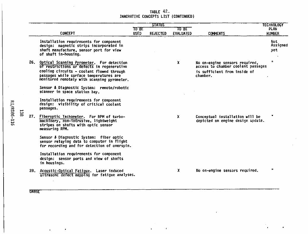
:;0 ...... .......... :;0 o ...... CO W 0'1 CO I
I+' ...... O'l
TABLE 42. INNOVATIVE CONCEPTS LIST (CONTINUED)
CONCEPT
Installation requirements for component design: magnetic strips incorporated in shaft manufacture, sensor port for view of shaft in-housing.
26. O~tical Scanning Pyrometer. For detection o restrictions or defects in regenerative cooling circuits - coolant flowed through passages while surface temperatures are monitored remotely with scanning pyrometer.
Sensor & Diagnostic System: remote/robotic scanner in space station bay.
Installation requirements for component design: visibility of critical coolant passages.
27. Fiberoptic Tachometer. For RPM of turbomachinery, non-intrusive, lightweight stripes on shafts with optic sensor measuring RPM.
Sensor & Diagnostic System: fiber optic sensor relaying data to computer in flight for recording and for detection of overspin.
Installation requirements for component design: sensor ports and view of shafts in housings.
SUTUS TIJB~ - - -- TO-lJ[ USED REJECTED EVALUATED
x
x
28. ACoustic-O~tical Fati~ue. Laser induced ultrasoncefect mapplng for fatigue analyses.
x
0IllJ5E
TECHNOLOGY PLAN .
COMMENTS
No on-engine sensors required, access to chamber coolant passages is sufficient from inside of chamber.
Conceptual installation will be depicted on engine design update.
tlo on-engine sensors required.
NUMBER
Not Assigned yet
"
"
"

;;0 ...... ";;0 o ...... CO w en 1.0 I ...... ......
en
0485E
TABLE 42. INNOVATIVE CONCEPTS LIST (CONTINUED)
CONCEPT
Sensor & Diagnostic System: remote/robotic laser source/sensor in space station bay coupled to computer to record component fatigue history for determination of servicing requirements.
Installation requirements for component design: visibility of critical fatigue susceptible components/access for laser source/sensors.
mTUS I U BE - - _ .. w-BE
USED REJECTED EVALUATED COMMENTS
TECHNOLOGY PLAN
NUt-IBEP.
Not Assigned yet
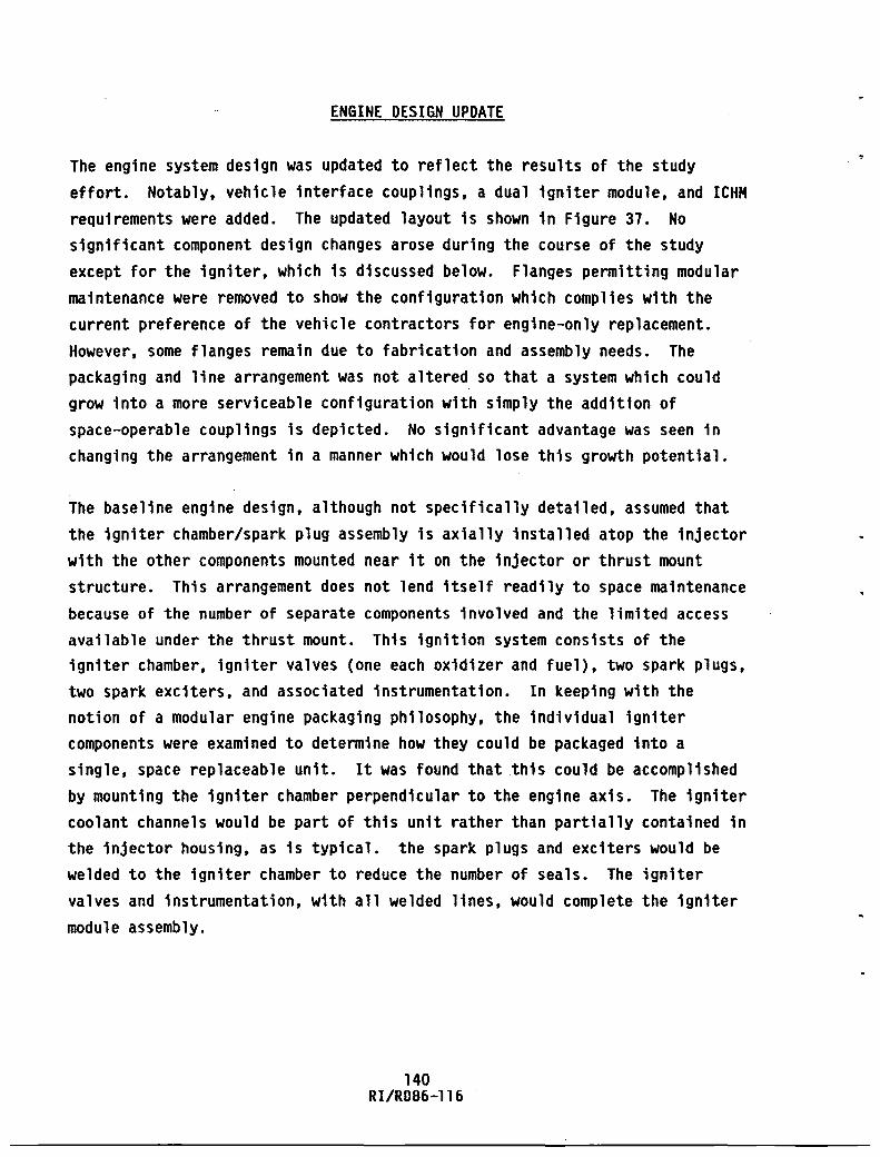
ENGINE DESIGN UPDATE
The engine system design was updated to reflect the results of the study effort. Notably, vehicle interface couplings, a dual igniter module, and ICHM requirements were added. The updated layout is shown in Figure 37. No significant component design changes arose during the course of the study except for the igniter, which is discussed below. Flanges permitting modular maintenance were removed to show the configuration which complies with the current preference of the vehicle contractors for engine-only replacement. However, some flanges remain due to fabrication and assembly needs. The packaging and line arrangement was not altered so that a system which could grow into a more serviceable configuration with simply the addition of space-operable couplings is depicted. No significant advantage was seen in changing the arrangement in a manner which would lose this growth potential.
The baseline engine design, although not specifically detailed, assumed that the igniter chamber/spark plug assembly is axially installed atop the injector with the other components mounted near it on the injector or thrust mount structure. This arrangement does not lend itself readily to space maintenance because of the number of separate components involved and the limited access available under the thrust mount. This ignition system consists of the igniter chamber, igniter valves (one each oxidizer and fuel), two spark plugs, two spark exciters. and associated instrumentation. In keeping with the notion of a modular engine packaging philosophy, the individual igniter components were examined to determine how they could be packaged into a single, space replaceable unit. It was found that this could be accomplished by mounting the igniter chamber perpendicular to the engine axis. The igniter coolant channels would be part of this unit rather than partially contained in the injector housing, as is typical. the spark plugs and exciters would be welded to the igniter chamber to reduce the number of seals. The igniter valves and instrumentation, with all welded lines, would complete the igniter module assembly.
140 RI/RD86-116


This modular igniter concept is shown in Figure 38. The unit is mounted perpendicular to the longitudinal axis of the engine so that it may be removed radially without disturbing the gimbal/thrust mount structure installation. For clarity, a disconnect coupling for this concept is not shown.
Replacement of this unit would first require disconnecting the igniter valve inlet lines and a multipin electrical coupling. A single fluid coupling would then be actuated to disconnect the assembly from the injector. This coupling would both serve as a fluid joint for the igniter combustion and coolant flows and as a structural attachment for the igniter module. Advanced fluid coupling concepts examined for use as duct joints would also be applicable for this module. A comparison of features between the modular and baseline igniter systems in shown in Table 43.
142 RI/R086-116


c::--'--
----'
I -
L --.
-
~ DUAL SPARK EXCITERS
, IGNITER FUEL VALVE
.---.-
-
~
'-....
--
v"--
IGNITER BODY
IGNITER OXIDIZER VALVE
I GN I TER/ INJECTOR --, INTERFACE /
'.1 I l' ~ I -I
,/
/ /
/ --i __ , ~ I
:?'\
(' ;< 1/ I
II I
~I Figure 38. Modular Igniter Concept
143 RI/RD86-116
TO INJECTOR FACE

Fluid Joints
Fluid Seals
Electrical Joints
Weight
Cost
TABLE 43. IGNITER COMPARISON
Baseline
6
7
(2 Valve Inlets 2 Valve Outlets 1 Igniter Body 2 Spark Plugs
5
(2 Exciters 2 Valves
• 1 Instrumentation
Modular
3
4
(2 Valve Inlets 2 Igniter Body)
2
(2 Exciters; Valves & Instrumentation Integrated into Exciter Couplings)
Negligible Difference
Baseline
144 RI/RD86-116
Initial cost higher
UniL repair cost higher Space service cost
lower

TECHNOLOGY PLANS
Technology development plans were generated for several of the innovative concepts evaluated as being technologically feasible with fruition expected within the time frames of interest. These technology development summaries are presented in this section for the selected concepts using a uniform format. A two-page summary is provided for each technology task. The first page describes the recommended technology by its objectives, current development status, and benefits. The technology type (focused or generic), development timeframe, and the components affected are also identified. A
brief Statement of Work is included to define the basic efforts to be performed. The second page of each summary discusses the impact of not developing the technology. Potential alternative technologies and the technical risks involved are provided. Finally, a technology advancement schedule identifies the technology subtasks with their schedule, and the test facilities required. The number at the top of each technology summary sheet is cross-referenced with the technology plan number in the concepts list.
145 RI/R086-ll6

OTV ENGINE TECHNOLOGY TASK NO.1
1.
TECHNOLOGY TASK TITLE: Turbine Shutoff Valve (TSV)
2. MAJOR TECHNOLOGY GROUP TITLE: Valves
3.
TECHNOLOGY TYPE: OTV FOCUSED -L GENERIC
4.
PROPULSION COMPONENT(S) AFFECTED: Turbopumps, actuators, electronic controller
5.
OBJECTIVE OF TECHNOLOGY ADVANCEMENT: Incorporate a turbine drive gas shut off valve into the engine
6.
TECHNOLOGY TIME FRAME: NEAR TERM _X__ INTERMEDIATE LONG RANGE
1.
STATE-OF-THE-ART LEVEL: Technology developed, requires design, fabrication, and testing
8.
BRIEF WORK STATEMENT: Design, fabrication, and testing of flightweight hot hydrogen (1100oR) shut off valve. Testing would be conducted on integrated components evaluator (ICE) engine.
9.
BENEFITS: 1). Reduces pump speed decay by - 33% resulting in shorter periods at
damaging critical speeds, increases pump life.
2). Eliminates need for pump brakes in tank head idle mode, simplifies
turbopump designs. 146
RIIRD86-116

OTV ENGINE TECHNOLOGY TASK NO.1
TECHNOLOGY TASK TITLE: Turbine Shutoff Valve (TSV)
10. IMPACT IF TECHNOLOGY NOT DEVELOPED: (Performance, Reliability, Cost,
Potential Alternatives): 1). Shorter turbopump lives
2). Pump brakes required
11. TECHNICAL RISKS: Risks are low . .
12. TECHNOLOGY ADVANCEMENT SCHEDULE AND COST:
FISCAL YEAR SCHEDULE 86 : 87 88 89 90 I 91 ! 92 93 94 95 96 I 97 I 98
SUBTASKS
1. DESIGN 2. FABRICAT ION 3. VALIDATION TESTS
1. ENGINEERING LAB 2. ICE AT SSFL
~-! I !-I
147 RI/RD86-116

OTV ENGINE TECHNOLOGY TASK NO.2
1. TECHNOLOGY TASK TITLE: Consolidated turbine shutoff (TSV) and turbine bypass valve (TBV).
2. MAJOR TECHNOLOGY GROUP TITLE: Valves
3. TECHNOLOGY TYPE: OTV FOCUSED ~ GENERIC
4. PROPULSION COMPONENT(S) AFFECTED: Turbopumps, main fuel throttling valve, actuators, electronic controller
5. OBJECTIVE OF TECHNOLOGY ADVANCEMENT: Combine the TBV and TSV into a single unit with one actuator.
6. TECHNOLOGY TIME FRAME: NEAR TERM INTERMEDIATE ~ LONG RANGE
7. STATE-OF-THE-ART LEVEL: Most sub-elements have been proven, but the combination of these elements in an actuator/valve assembly is a new development. Preliminary design sketch generated.
8. BRIEF WORK STATEMENT: Design, fabrication, and testing of a prototype and flightweight consolidated main fuel throttling valve and turbine shutoff valve (electric motor actuator, low noise, low torque valve)
9. BENEFITS:
1). Weight Savings
2). Reliability improvement with single unit
148 RI/RD86-116

OTV ENGINE TECHNOLOGY TASK NO.2
TECHNOLOGY TASK TITLE: Consolidated TSV and TBV
10. IMPACT IF TECHNOLOGY NOT DEVELOPED (Performance, Reliability, Cost,
Potential Alternatives): Separate TBV and TSV (see technology
Task No.1) resulting in increased weight and lower overall reliability
11. TECHNICAL RISKS:
1). Hot H2 leak across metal/metal seals
2). Precision clutch for pneumatic override
12. TECHNOLOGY ADVANCEMENT SCHEDULE AND COST:
FISCAL YEAR SCHEDULE IB6 87 i 88 89 i 90 I 91 : 92 ' 93 94
SUBTASKS I . I
1. PROTOTYPE UNIT ! I ; I
2. FLIGHTWEIGHT I \
1. ENGINEERING LAB 2. ICE AT SSFL
!
I I i
1 ! I
I I ,
-----I , I
!
149
RI/RD86-116
, !
! I I i i
--' i i I
I !
95 I 96 97 : 98
I I
I ! :
I
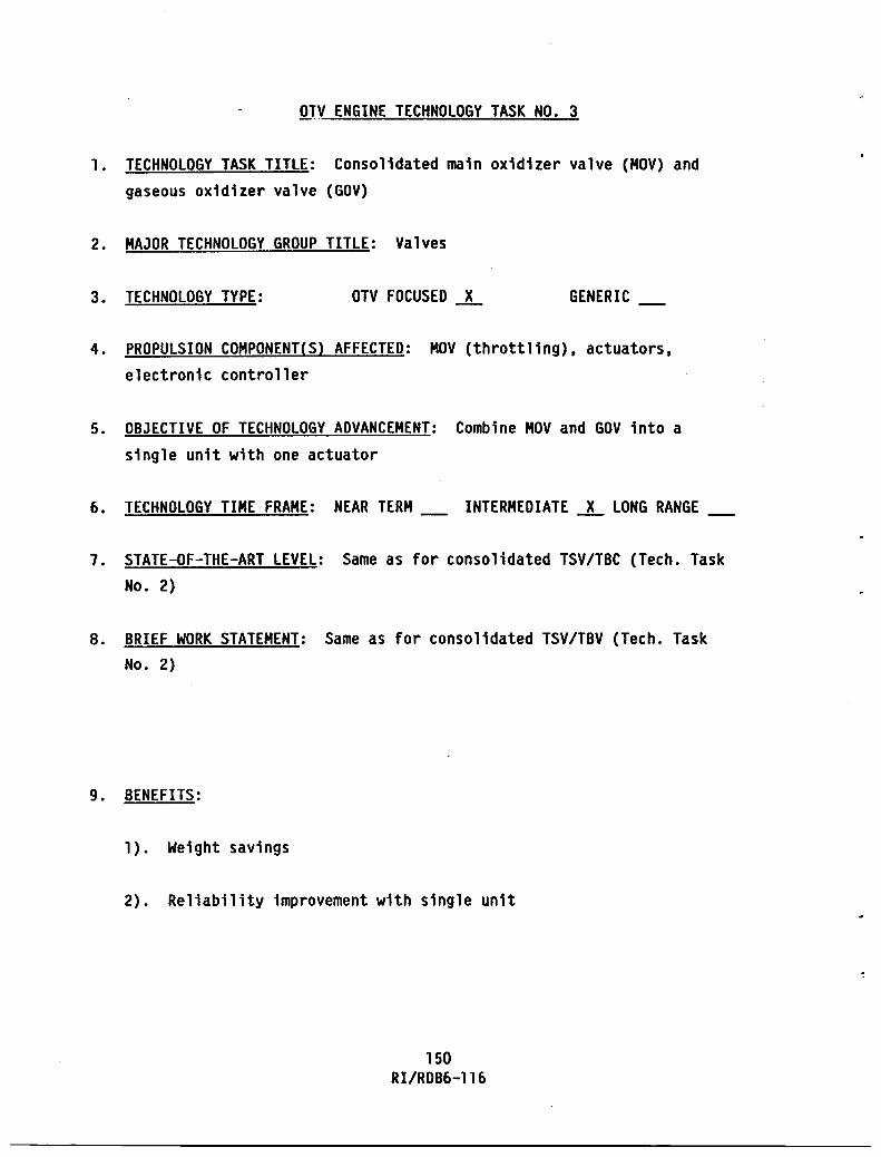
OrV ENGINE TECHNOLOGY TASK NO.3
1. TECHNOLOGY TASK TITLE: Consolidated main oxidizer valve (MOV) and gaseous oxidizer valve (GOV)
2. MAJOR TECHNOLOGY GROUP TITLE: Valves
3. TECHNOLOGY TYPE: OTV FOCUSED --L GENERIC
4. PROPULSION COMPONENT'S) AFFECTED: MOV (throttling), actuators, electronic controller
5. OBJECTIVE OF TECHNOLOGY ADVANCEMENT: Combine MOV and GOV into a single unit with one actuator
6. TECHNOLOGY TIME FRAME: NEAR TERM INTERMEDIATE --L LONG RANGE
1. STATE-OF-THE-ART LEVEL: Same as for consolidated TSV/TBC (Tech. Task No.2)
8. BRIEF WORK STATEMENT: Same as for consolidated TSV/TBV (Tech. Task No.2)
9. BENEFITS:
1). Weight savings
2). Reliability improvement with single unit
150 RIIRD86-116

OTV ENGINE TECHNOLOGY TASK NO. 3
TECHNOLOGY TASK TITLE: Consolidated MOV and GOV
10. IMPACT IF TECHNOLOGY NOT DEVELOPED: (Performance, Reliability, Cost, Potential Alternatives): Separate MOV and GOV would be required
resulting in increased weight and lower overall reliability
11. TEC_HNICAL RISKS:
1). Precision clutch for pneumatic override
12. TECHNOLOGY ADVANCEMENT SCHEDULE AND COST:
FISCAL YEAR SCHEDULE 86 87 88 89 90 91192 93 j 94 95 96 ; 97 I 98
SUBTASKS
1. PROTOTYPE UNIT 2. FLIGHTWEIGHT I
I
i I
I I I 1. ENGINEERING LAB
2. ICE AT SSFL
, : ! i
I I : ~t-;- I I
i ! I , i i
-, I
151
RI/RD86-116
:
i i ,
i i
i I
! I
I -~-
! 1 1 q= ! :0 , I I I I !
: I
I , I I
I , ,
I I I i I I , I
I , I !
: :
: ! i
i i I I
I
I
I i I
! !
I ,

OTV ENGINE TECHNOLOGY TASK NO.4
1. TECHNOLOGY TASK TITLE: Electric Actuated Cartridge Valves
2. MAJOR TECHNOLOGY GROUP TITLE: Valves, Space Maintenance
3. TECHNOLOGY TYPE: OTV FOCUSED GENERIC ~
4. PROPULSION COMPONENT(S) AFFEcTED: Valves, Duct1ng, and Flanges
5. OBJECTIVE OF TECHNOLOGY ADVANCEMENT: Develop cartridge coupling and seat seal replacement capability to enhance space-based servicing.
6. TECHNOLOGY TIME FRAME: NEAR TERM ~ INTERMEDIATE LONG RANGE
7. STATE-OF-THE-ART LEVEL: Prototype of cartridge valve fabricated.
8. BRIEF WORK STATEMENT:
1. Identify coupling and seal replacement methods. 2. Perform operational analysis. 3. Fabricate servicing tools. 4. Perform operational space servicing tests.
9. BENEFITS:
Enhanced space-based maintainability. Improved servicing reliability. Lower servicing costs.
152 RI/R086-l16

OTV ENGINE TECHNOLOGY TASK NO.4
TECHNOLOGY-TASK TITLE: Electric Actuated Cartridge Valves
10. IMPACT IF TECHNOLOGY NOT DEVELOPED: Space-based repairs and replacements
more difficult. Higher risk of seal damage during space installation.
11. 1ECHNICAL RISKS: Low risk - seal damage upon space servicing.
12. lECHNOLOGY ADVANCEMENT SCHEDULE AND COST:
SCHEDULE I 86 i 87
I SUBTASKS !
1.
2.
3.
4.
IDENTIFY COUPLING REPLACEMENT METHODS PERFORM OPERATIONAL ANALYSIS FABRICATl SERVICING TOOLS
i I
!
PERFORM OPERATIONAL SPACE SERVICING TESTS!
1. ENGINllRING LAB
01 , I r [] I
i i !
88 89 90
, i ,
153
RI/RD86-116
FISCAL YEAR 91 ; 92 93 94 ' 95 ; 96
I , I I I
i ! i i , I I ,
I
97 98 1

OTV ENGINE TECHNOLOGY TASK NO.5
1. TECHNOLOGY TASK TITLE: Modular Igniter
2. MAJOR TECHNOLOGY GROUP TITLE: Space Maintainability
3. TECHNOLOGY TYPE: OTV FOCUSED ~ GENERIC
4. PROPULSION COMPONENT(S) AFFECTED: Ignition system components: Igniter body, spark plugs, spark exciters, igniter valves, and igniter instrumentation as well as igniter interface of the main injector.
5. OBJECTIVE OF TECHNOLOGY ADVANCEMENT: Improve maintainability of the ignition system.
6. TECHNOLOGY TIME FRAME: NEAR TERM ~ INTERMEDIATE LONG RANGE
7. STATE-OF-THE-ART LEVEL: Module elements well defined; integrated unit requires development.
B. BRIEF WORK STATEMENT: Prepare preliminary design of igniter module and compatible injector interface. Perform thermal and structural analysis to verify performance and life goals. Prepare preliminary design of test configuration for use with the Integrated Components Evaluator.
9. BENEFITS: Reduced number of fluid joints and seals. Reduced number of electrical interconnects. Enhanced space replacement capability. Increased engine reliability. Faster engine turnaround. Reduced life-cycle costs.
154 RI/RDB6-1l6

OTV ENGINE TECHNOLOGY TASK NO.5
TECHNOLOGY TASK TITLE: Modular Igniter
10. I~PACT IF TECHNOLOGY NOT DEVELOPED: (Performance, Reliability, Cost, Potential Alternatives): Space servicing costs associated with the ignition system higher due to longer replacement task times as
requirements to remove engine for igniter maintenance. Engine reliability
lower because of additional interconnects in non-modular system. Component cost lower than modular design.
11. lECHNICAL RISKS: Low
12. TECHNOLOGY ADVANCEMENT SCHEDULE AND COST:
FISCAL YEAR SCHEDULE I 86 j 87 ; 88: 89 '90 91 192 93 94 95 96 97 I 98
I I I I I
SUBTASKS 1 I ! I I I : I !CJ I I
1. PRllIMINARY DESIGN ! I
I 1
2. DESIGN ANALYSIS Ie i I i
I i ~-
I , 3. TEST CONFIGURATiON i I ,
~! I I i ! i ;
DESIGN
I
! i ! I
I i
I I '/
---------------------+--~--r_~------r_~--~---------~~--------
NONE
155
RI/RD86-116

OTV ENGINE TECHNOLOGY TASK NO.6
1. TECHNOLOGY TASK TITLE: Lightweight, high strength composite materials (for non-rotating OTV engine components)
2. MAJOR TECHNOLOGY GROUP TITLE:
3. TECHNOLOGY TYPE: OTV FOCUSED GENERIC ~
4. PROPULSION COMPONENT(S) AFFECTED: Non-rotating OTV engine components, i.e., housings, ductings
5. OBJECTIVE OF TECHNOLOGY ADVANCEMENT: Reduce engine weight, increase performance
6. TECHNOLOGY TIME FRAME: NEAR TERM INTERMEDIATE ~ LONG RANGE
7. STATE-OF-THE-ART LEVEL: Developmental
8. BRIEF WORK STATEMENT: To develop low pressure propellant ducts including: ducting (including elbows) articulated bellow joints and flanges, using different kinds of SiC reinforced composite materials.
9. BENEFITS: The composite propellant ducts will save 24% of the weight. Using the superplastic forming and diffusion bonding technique will save significant amount of fabrication cost.
156 RI/RD86-116

OTV ENGINE TECHNOLOGY TASK NO. 6
TECHNOLOGY TASK TITLE: Lightweight, high strength composite materials
(for non-rotating OTV engine components)
10. IMPACT IF TECHNOLOGY NOT DEVELOPED: (Performance, Reliability, Cost,
Potential Alternatives): A potential 24% total engine weight saving cannot be realized.
11. TECHNICAL RISKS: Medium: (1) The DB processing of SiC/Al may not be practical for hardware fabrication (2) The bellow may not be formed superplastically
12. TECHNOLOGY ADVANCEMENT SCHEDULE AND COST:
FISCAL YEAR SCHEDULE 86 i 87 ' 88 89 : 90 91 92 93 : 94 ~ 95 96 97
1.
! , I i
I "ll\SKS I
r-1 ! :
I i I I I I , : I
I i I SPF/DB OF SiC/Al r-b !
I "
COMPOSITE I ! j I I , , i
SUBCOMPONENT FABRICATION I ! I
I I ; i , , I ! i , , !
SUB
2. 3. DUCTING ASSEMBLY 4. TESTING
' 98 I I , I I
1 i i
! , ; I
! , I I
-------------------------------+-~---~I-----~--~--~-----+ ~~ ~--l i I
1. __ S_S_F_L ____________________ ~ ______ ~~~---.--------------------____ ~
157 RI/RD86-116

OTV ENGINE TECHNOLOGY TASK NO.7
1. TECHNOLOGY TASK TITLE: High expansion ratio nozzle mechanical retraction/ extension devices
2. MAJOR TECHNOLOGY GROUP TITLE: Nozzle
3. TECHNOLOGY TYPE: OTV FOCUSED GENERIC -L
4. PROPULSION COMPONENT(S) AFFECTED: Extendable Nozzle
5. OBJECTIVE OF TECHNOLOGY ADVANCEMENT: Develop mechanical retraction/ extension devices for nozzle
6. TECHNOLOGY TIME FRAME: NEAR TERM INTERMEDIATE -L LONG RANGE
7. STATE-OF-THE-ART LEVEL: Four preliminary designs currently exist. Demonstration tests of deployment on solid rocket boosters.
8. BRIEF WORK STATEMENT: 1). Design studies
2). Fabrication studies 3). Structural verification tests
9. BENEFITS: Performance increase from higher expansion nozzle. Smaller stored engine envelope for shuttle bay transport.
158 RIIRD86-l16

OTV ENGINE TECHNOLOGY TASK NO.7
TECHNOLOGY TASK TITLE: High expansion ratio nozzle mechanical retraction/
extension devices
10. IMPACT IF TECHNOLOGY NOT DEVELOPED: (Performance, Reliability, Cost,
Potential Alternatives): Fixed nozzle (limited performance). Longer engine package while stored in shuttle bay, or need to utilize complex
geometric means to provide high expansion ratio in a short length.
11. TECHNICAL RISKS: Mechanical complexity, reliability, weight, and structural integrity
12. TECHNOLOGY ADVANCEMENT SCHEDULE AND COST:
FISCAL YEAR SCHEDULE B6 87 88 89 ' 90 : 91 • 92 93 ! 94 95 96 I 97 198
I I SU8TASKS , i
1. DESIGN :[ 2. FABRICATION !
STRUCTURAL VERIFICATIO~ 3. TESTS
1. ENGINEERING LAB 2. ICE AT SSFL
i ,
1 f--I i i I
r-. i I I
i I _1 ,
I ! , H I .
159 RI/RD86-116
I
I i
I , i i
! I I I I I !
I I
I
I

OTV ENGINE TECHNOLOGY TASK NO.8
1. TECHNOLOGY TASK TITLE: Extendable nozzle high pressure coolant fluid
interconnects
2. MAJOR TECHNOLOGY GROUP TITLE: Nozzle
3. TECHNOLOGY TYPE: OTV FOCUSED GENERIC ~
4. PROPULSION COMPONENT(S) AFFECTED: Extendable nozzle
5. OBJECTIVE OF TECHNOLOGY ADVANCEMENT: Develop high pressure remote coolant seals capable of hermetic operation over numerous cycles
6. TECHNOLOGY TIME FRAME: NEAR TERM INTERMEDIATE ~ LONG RANGE
1. STATE-OF-THE-ART LEVEL: Limited experience with supply of coolant to movable sections
8. BRIEF WORK STATEMENT:
1). Design studies 2). Fabrication studies 3). Structural verification tests
9. BENEFITS: Performance increase from higher expansion nozzle. Performance increase from added nozzle heat load for turbine drive.
160 RI/RD86-l16

OTV ENGINE TECHNOLOGY TASK NO.8
TECHNOLOGY TASK TITLE: Extendable nozzle high pressure coolant fluid
interconnects
10. IMPACT IF TECHNOLOGY NOT DEVELOPED: (Performance. Reliability. Cost.
Potenlial Alternatives): Fixed nozzle (limited performance). Longer engine package while stored in shuttle bay. or need to utilize complex geometric means to provide high expansion ratio in a short length.
11. TECHNICAL RISKS: Reliability of seal integrity. Leakage could cause disabling engine performance degradation
12. TECHNOLOGY ADVANCEMENT SCHEDULE AND COST:
FISCAL YEAR SCHEDULE 86 87 88 89 ! 90 ; 91 l 92 93· 94 95 96 97 I 98 I
SU8TASKS
1. 2. 3.
1. 2.
DE.SIGN FAB~ICATION I VE.~I~ICATION TFSTING
ENGINEERING LAB I Cf:. AI SSF L
I
! I , I i
!=b i t ,-+--i l ~ -----.
I ! I i
I, ! I ! I
I i Ii i I iii
.~:~J ; I i j--, Ii I :-
~I !
161
RI/RD86-116
I

OTV ENGINE TECHNOLOGY TASK NO.9
1. TECHNOLOGY TASK TITLE: Nozzle segmentation and interface seals
2. MAJOR TECHNOLOGY GROUP TITLE: Nozzle
3. TECHNOLOGY TYPE: OTV FOCUSED GENERIC ~
4. PROPULSION COMPONENT(S) AFFECTED: Extendable Nozzle
5. OBJECTIVE OF TECHNOLOGY ADVANCEMENT: Develop nozzle segment interface technology to provide smooth. leak-free and reliable seals between,H2 cooled and radiation cooled segments
6. TECHNOLOGY TIME FRAME: NEAR TERM INTERMEDIATE ~ LONG RANGE
7. STATE-OF-THE-ART LEVEL: Some related experience on solid rocket
boosters
8. BRIEF WORK STATEMENT: Design, fabrication, and testing of segment interface seals integrated with overall retractable nozzle development.
9. BENEFITS: Performance increase from higher expansion nozzle. Smooth interface seals minimize added nozzle boundary layer drag losses.
162 RI/RD86-ll6

OTV ENGINE TECHNOLOGY TASK NO.9
TECHNOLOGY TASK TITLE: Nozzle segmentation and interface seals
10. IMPACT IF TECHNOLOGY NOT DEVELOPED: (Performance, Reliability, Cost, Potential Alternatives): Fixed nozzle (limited performance) longer engine package
11. l~CHNICAL RISKS: Reliability of seal integrity. Leakage could cause nozzle damage and performance degradation
12. TECHNOLOGY ADVANCEMENT SCHEDULE AND COST:
FISCAL YEAR -. SCHEDULE 86 I 87 ' 88 J 89 90 91 i 92 93 94 i95 96 : 97
I j I i I I SUBTASKS i I I i I i i
-h ! i I I j
1. DE,SlGN 2. FABRICATION 3. VERIFICATION TESTING ',9~--·~j~ . ,
I I --, , I I
;
1. ENGINEERING LAB 2. ICE AT SSFL
163
RI/RD86-116
98
!

OTV ENGINE TECHNOLOGY TASK NO. 10
1. TECHNOLOGY TASK TITLE: Space Operable Fluid Disconnects
2. MAJOR TECHNOLOGY GROUP TITLE: Space Maintainability
3. TECHNOLOGY TYPE: OTV FOCUSED GENERIC ~
4. PROPULSION COMPONENT(S) AFFECTED: Engine/Vehicle interface joints and all fluid components requiring space replacement capability
5. OBJECTIVE OF TECHNOLOGY ADVANCEMENT: Provide a demonstrated space operable disconnect technology with which engine space maintenance plans can be confidently made
6. TECHNOLOGY TIME FRAME: NEAR TERM INTERMEDIATE ~ LONG RANGE
1. STATE-OF-THE-ART LEVEL: Many devices have been identified at conceptual level. No current devices exist which meet the needs of cryogenic space engine systems.
8. BRIEF WORK STATEMENT: Prepare conceptual designs of disconnect devices. Assess concepts and rank for OTV applicability. Perform structural, thermal operational, or other analysis as needed to evaluate the better candidates. Prepare preliminary flight design of selected concepts. Establish verification test goals and plan. Prepare detail design of breadboard version of concept. Fabricate test unit. Conduct operational and performance testing.
9. BENEFITS: Reduced life cycle costs. Faster engine turnaround
164 RI/RD86-ll6

[T~ ENGINE TECHNOLOGY TASK NO. 10
TECHNOLOGY TASK TITLE: Space Operable Fluid Disconnects
10. IMPACT IF TECHNOLOGY NOT DEVELOPED (Performance, Reliability, Cost,
Potential Alternatives): Space servicing costs higher due to longer task times required to replace engine or components.
11. TECHNICAL RISKS: Medium
12. IlCHNOLOGY ADVANCEMENT SCHEDULE AND COST:
-. SCHEDULE
SUBTASKS
l. CONClPTUAL DESIGN I 2. ASSlSS CONCEPTS I 3. ANALYSIS i 4. PRELIMINARY DESIGN 5. TEST PLAN 6. DETAIL DESIGN 7. FABRICATION 8. TEST
ENGINEERING LAB
86 i 87 88 89 90 91
0 0 0 I o cj . ell .-.J 10 ~ P
I I I
l I
165
RI/RD86-116
FISCAL YEAR 92 93 94 95 96 : 97 98
! , i I ! I I
I I I
i i I I I I
! I I I , i I I I
! !
I , , I I
! , ;
I I
I


." o :0 ~ 0-o 0> . til . -w :0 m :::. U'I ~ U'I
;c ...... -..... ;c 0 CO C'\ I ...... ......
C'\
...... I ......
TABLE 1-1. VEHICLE DERIVED REQUIREMENTS FOR ICHM SYSTEM
PAGE 1-1
+-----------------------------------------------------------------------------------------------------+-+' I SOURCE - > I MARTI N I GENERAL I BOE I NG G. E. I ROCKET DYNE I it I ' I I MARIETTA I DYNAMICS AEROSPACE GRUMMAN I ASSUMPTIONS I I, ~--------------------------~--------------~--------------~--------------+--------------~--------------~-+, +--------------------------+--------------~--------------~--------------+--------------+--------------+-~ I I I I I I I. GENERAL INFORMATION I I
I-LAST REVIEW BRIEFING I I I I-RECEIVE MONTHLY REPORTS? I I-STUDY FOCUS I I-SPONSORING AGENCY I I-PRIME CONTRACTOR
I-SUBCONTRACTOR
I-CONTRACT NUMBER I I-OTHER RELATED CONTRACTS I
I I 'PHASE I REVIEWIMIDTERM REVIEWIPHASE II FIR5TIPHA5E II FIRST:
BRIEFING BRIEFING REVIEW I REVIEW (J,UNE 84) (6/26/84) (JULY 84) I (7/17/84)
Y, (6TH) Y. (3RD) N N
PROPULSION PROPULSION AEROAS5IST AEROAS5IST (LOW LID) (MID LID)
NASA-LERC NASA-LERC NASA-MSFC NASA-MSFC
PWA ALRC
EAGLE ENGRG GOODYEAR . GRUMMAN
127985 L-B14740 NAS 8-35095 NAS 8-35096
OTV CONCEPT OTV CONCEPT DEFINITION t. DEFINITION t.
ISYST. ANALYSIS. ISYST. ANALYSIS I (NASA-MSFC) (NASA-MSFC) I
~--------------------------+--------------~--------------~--------------+--------------+--------------+-+
it ITEMS RELEVANT TO THE ICHM SYSTEM
~ D c:: ...... ;C 1'T'Ie:: 3:1'T'1 I'T'I ::z::: z ...... ::t:> --I ("") -U (/) r- -u
I'T'II'T'I "T1 Z 000 ;C I'T'I ......
;C X ............ ("")e:: ...... ::z::: I'T'I 3:0
(/)
-< (/) --I I'T'I 3:
.I
~ ~ :II :D g 0 ~ (') !!. 7'!:' a. ~ ~ (1) ID _
D -3: :; . -o (1) :I 3
a o :J !!.

'TI o ;:Q
~ 0-o Q) . DI . -W ;:Q
m ~ U1 .!.. U1
;0 .......
......... ;0 0 CO 0'\ I ~
~
0'\
~
I N
Table 1-1 (Cont'd)
PAGE Il-l VEHICLE DERIVED REQUIREMENTS FOR ICHM SYSTEM 21-Aug-84
+-----------------------------------------------------------------------------------------------------+-+ SOURCE -> MARTIN I GENERAL BOEING G.E. I ROCKETDYNE 1*1
MARIETTA I DYNAMICS AEROSPACE GRUMMAN I ASSUMPTIONS , , +--------------------------+--------------+--------------+--------------+--------------+--------------+-+ +--------------------------+--------------+--------------+--------------+--------------+--------------+-+ I I I I I I I I 1 I. I1ISSION REQUIREI1ENTS I I I I
I I I I I I-TARGET ORBITS IGEOSYNCHRONOUSIGEOSYNCHRONOUSI-GEOSYNCHR. I-GEOSVNCHR. I GEOSYNCHRONOUS I I I l-bHR POLAR l-bHR POLAR I (PRIMARY) I
I -BASELINE I1ISSIONIS'
(I1OSTLY I1SFC 1100. REV.b'·
I-MPS DELTA-Va LEO-GEO GEO-LEO
:-DELTA-V LOSSES I I I-NUMBER OF PERIGEE BURNS I
~
I I-MOLNIVA I-MOLNIVA I I I I -5 x GE.O I -5 Ie GEO I I I I I I
I)DEL. lb KLB,ll)DEL. 10 TO 11)DEL. 20 KLB,ll)DELlVERY 11)DELIVER UP IX RETURN EMPTVI Ib KLB,(GEO I RETURN EMPTVI UP TO 55KLB I TO 16 KLB TOI AEROASSISTEDI PLATFORM ANDI AEROASSISTEDI I GEO AND I UNMANNED I LSSCDS) I UNMANNED I I RETURN I
2)DEL. 13 KLB,12)DEL. 13 KLB,12)DEL. 14 KLB,12'MANNED ROUNDI2)MANNED ROUND I ROUNDTRIP, I ROUNDTRIP, I ROUNDTRIP, I TRIP TRIP TO GEO I AEROASSISTEDI AEROASSISTED' AEROASSISTEDI CREW OF 5-6 WITH 13 KLB I I1ANNED I I1ANNED I1ANNED I PAVLOAD I
13'GEO SATELL. 3)DEL. b I(LB, 13)SERVICING 3'UNI1ANNED SATI NASA,DOD,ETC RETURN 2 t<Li:l1 SERVICING- I +UNMANNED AEROASSISTEDI DELIVER 6K, , SERVICING UNMANNED I RETURN 3K ,
4'MANIFESTED IB'LOW THRUST COMMERCIAL DELIVERV SATELLITES MISSIONS
I 13985 FPS .... 14000 FPS "14000 FPS "'14000 FPS I bbOO FPS ..... bbOO FPS "'700(' FPS "'7000 FPS I AlB RETURN AlB RETURN AlB RETURN AlB RETURN I I .... 325 FPS .... 100 FPS I FUNCTION IF IW, I I .BURNS,ETC) I I SINGLE BURN POSSIBLY BASELINE I SMALL NR OF IX I NOMINAL MULTI-BURNS 12 PERIGEE (:jURNI IBURNS POSSIBLE'
* ITEMS RELEVANT TO THE ICHM SYSTEM
~ .. ::D :::0 g 0 f () f i . ~ CI = s: :;
. 5- c.r ~ 3
& g e.

." o ;:0 3: 0-o CO . C3 . -Co)
;:0 m ::: U1 ~ U1
;:0 ....... "-;;0 ~
o I CO <..oJ 0'\ I ~
~ 0'\
t- ~
Table 1-1 ~cont'd)
PAGE 11-2 VEHICLE DERIVED REQUIREMENTS FOR ICHM SYSTEM 21-Aug-B4
~+----------------------------------------------------------~------------------------------------------+-+ SOURCE - > MARTI N I GENERAL BOE I NG G. E. I ROCKET DYNE I * I
MARIETTA I DYNAMICS AEROSPACE GRUMMAN I ASSUMPTIONS I I +--------------------------+--------------+--------------+--------------+--------------+--------------+-+ +--------------------------+--------------+---------~----+--------------+--------------+--------------+-+ I I I I I I I I-AEROASSIST MANEUVER I UP TO 3 PASS 1 OR 2 PASS I SINGLE PASS I SINGLE PASS I SINGLE PASS IXI I I 1 NOMINAL 2 NOMINAL I I I NOMINAL I I I I I I I I I :-AEROASSIST DELTA-V I 7800 FPS A7000 FPS I ~7S00 FPS I A7000 FPS I ~7000 FPS I I I I I I I
• I-SPACE STATION ORBIT: I I I I ALTITUDE I 250 N.M. 220 N.M. 220 N.M. 220 N.M. 220 N.M. I I I INCLINATION I 2B.S DEG 26.5 DEG 26.S DEG 2B.S DEG I I I I I I +--------------------------+--------------+--------------+--------------+--------------+--------------+-+
* ITEMS RELEVANT TO THE lCHM SYSTEM
~ • ::a :0 o 0
=- ~ of ~ • = o _ - ::J ~ -!!. CD o ~ :::. ::J
~ o ::J CD

." o ~ ~ 0-o CD . ~ -Co>
~ m :: U1 .:.. U1
::0 ...... ...... ::0 ...... C I CO ~ C"I I ...... ......
C"I
',able 1-1 (cont'd)
PAGE 111-1 VEHICLE DERIVED REOUIREMENTS FOR ICHM SYSTEM 21-Au~-84
+-----------------------------------------------------------------------------------------------------+-+ I SOURCE -) I MARTIN GENERAL I BOEING \ G.E. \ ROCKET DYNE 1*\
I MARIETTA DYNAMICS I AEROSPACE \ GRUMMAN I ASSUMPTIONS I I +--------------------------+--------------+--------------+--------------+--------------+--------------+-+ +--------------------------+--------------+--------------+--------------+--------------+--------------+-+
Ill. OTV OPERATIONS
-DELIVERY TO SPACE STATION
DISASSEMBLED \ II EMPTY, I IN STS PL BAY I
-LAUNCH II RECOVERY FROM 551 RMS, GRAPPLE \
-MANEUVERS AROUND STATION I UNDEFINED I ACS,MMU.OMV I \
I-TYPICAL MISSION I
TIMELINESI SEE ATTACHED
I-TVPICAL MAINTENANCE OPS
I-CONTINGENCY RETURN
I I SEE ATTACHED \ IT ANK HEAD IDLE I OR ACS I
DISASSEMBLED II EMPTY,
IN STS PL BAY
SEE ATTACHED
SEE ATTACHED
OMV, RMS
MPS I NACTI VE WIIN 3 MILES
OF STATION
DISASSEMBLED IN STS CARGO
BAY
I I I
DISASSEMBLED IX II EMPTV. I
IN STS PL BAY I
RMS
RMS.ACS.OMV
SEE ATTACHED
SEE ATTACHED
THIM OR ACS • MAYBE RESCUE
VEHICLE
I IX I IX I I I IX I IX I IX I I I
t--------------------------+--------------+--------------+--------------+--------------+--------------+-+
* ITEMS RELEVANT TO THE ICHM SYSTEM
~ ~
-a ~ f ::JJ C't 0 ~ ()
i i ~ CD . -o -3: 5" 50 S' :I 3 ~ o :J e.

"11 o ;0 :r: 0-o ~ ~ -w ;0 m :: U'I .:., U'I
;;0 ....... --;;0 ......
°1 COOl 0'\ 1 ......
...... 0'\
., , '"
Table 1-1 (cont1d)
PAGE IV-l VEHICLE DERIVED REOUIREMENTS ~OR lCHM SYSTEM 22-Aug-B4
+-----------------------------------------------------------------------------------------------------+-+ I SOURCE -> I MARTIN I GENERAL I &OEING I G.E. I ROCKETDVNE 11t1' I I MARIETTA I DVNAMICS I AEROSPACE I GRUMMAN I ASSUMPTIONS I I +--------------------------+--------------+--------------+--------------+--------------+--------------+-+ +--------------------------+--------------+--------------+--------------+--------------+--------------+-+ I I I I I IV. VEHICLE DESCRIPTION I I I I
I-BASELINE VEHICLE
I I I I-MASS FRACTION I I-NOMINAL PROPELLANT I
I-H2 TANKS I 1-02 TANKS
'-BASING MODE
-BASELINE AEROASSIST DEVICE
-LIFT-TO-DRAG RANGE
LOAD
i-ENGINE DIRECTION WHEN I AEROBRAKING
I-ENGINE PROTECTION DURING
MODULAR, REUSAI:ILE
0.B64
42 KLB
2 ,SPHERICAL
2,SPHERICAL
MODULAR. REUSABLE
0.893
I I I CONVENTIONAL, IREUSABLE CORE,I MODULAR, IX
REUSABLE IWI DROP TANKS, I REUSABLE, IMAV BE STAGED POSSIBLY I STAGED OR
I I I
.... 0.9
WITH DROP TANKS
..... 0.86-0.90
153 I<LB,4 TANKS: 55 I,LB IUP TO 130 KLB I
VARIABLE 12b I<LB,2 TANKS I I 2/4,SPHER.
2/4,SPHER.
11,SPHER./CVL. I
1 ,SPHER I CAL
I I 1 ,ELLIPSOIDAL I I 1 ,ELLIPSOIDAL
SPHERICAL
SPHERICAL
SPACE STATION ISPACE STATION STS/SPACE STS/SPACE SPACE STATION IX
LIFTING LIFTING BRAKE ElRAKE
BUT CONSIDER BALLUTE
AND BI-CONIC
FORWARD FORWARD
I LIKELV TO IFAVOR BALLUTE
BUT LOOKING AT LIFTING
BRAI:E f.t SLED
O(L/D(O.75
AFT, SOME FORWARD
BICONIC WITH BODY FL.AP
O.75<L/D<1.5
AFT
-FAVOR COOLED I-HEAT SHIEL.DS I-I:IODV FL.AP
1t ITEMS RELEVANT TO THE ICHM SYSTEM
I PROBABLV I X LIFTING
BRAKE
LOW LID
FORWARD
DOORS OR IX
.!
---• :II :::D g 0 ~ (') !!. ~ .t ~ :I CD . -C -3: 5" ~ S' :I 3
l!1: o ::s e!.

"11 o ;a ~ 0-o CD . Cl . -Co)
;a m :< C1t ~ C1t
;0 ...... "-;0 0 co en I ..... .....
en
..... I
en
Table 1-1 (cont'd)
PAGE IV-2 VEHICLE DERIVED REQUIREMENTS FOR ICHM SYSTEM 22-Aug-B4
+-----------------------------------------------------------------------------------------------------+-+ I SOURCE -) I MARTIN I GENERAL I BOEING I G.E. I ROCKETDVNE 1*1 I I MARIETTA I DYNAMICS I AEROSPACE I GRUMMAN I ASSUMPTIONS I I +--------------------------+--------------+--------------+--------------+--------------+--------------+-+ +--------------------------+--------------+--------------+--------------+--------------+--------------+-+ I AEROPASS I I DOORS I-JETT. NOZZLESI-RETRACTABLE I RUN ENGINE I I I-BLEED COOLINGI-WATER SPRAY NOZZLES I
I-RUN ENGINE I I-RADIATION I I I
-OTHER VEHICLE TYPES I-CONVENTIONAL I-TOROID. ACC I-MODULAR ACC I-38FT INTERNALI-ACC OTV
-STORAGE AND SHELTER
, I I-BASELINE AVIONICS
I I I-ELECTRICAL POWER SYSTEM I I I
I-MANRATlNG
I I I I-SAFETY REQUIREMENTS I I
~
TYPE I-TOROID STS I-CONVENTIONAL: TANI( VEHICLE I-BICoNIC OTY I BASED I STS BASED I-H-l,H-1M, I-VARIOUS
ISPACE STATION I SERVICE I BERTH I
I-MAIN, FUl:":L I CELLS I-BACI~UP I SMALL I I BATTERIES
FO/FS
NHB 1700.7A NEAR S/S,STS
-CENTAUR I OH-2M,oH-3SB I STAGING DERIVATIVES I CONCEPTS
55 SHELTER I SPACE HANGAR POSSIBLY
PARTIALLY PRESSURIZED
HI-SPEED SERIAL DATA
£IUS
ITRIPLE REDUND. I FUEL CELL I 2 I-:W NUM.
3.5 I(W PEAK I
MUTIPLE l )O.99a,F/S ENGINES
DR SINGLE WITH BACKUP
FS/FS
SPACE HANGAR 'X -BOTH EVA OR I
IVA TO BE I CONS I DERED I ,
I I ADEQUATE IXI
REDUNDANCY t " . ADV. ELECTR. I I , ,
, FUEL CELL, IX' IBATTERY BACKUP I , I I I , I I
I : FO/FS? IX:
I I I I I I I I
NHB 1700.7A IXI t' NEAR SS,STS I I I I I
* ITEMS RELEVANT TO THE ICHM SYSTEM
). ~
-a • :D :::a g 0 ~ (')
it ~ ~ ~ . -o -c 5" - .... II. ~ o ... ~ ::J
~ o ::J e.

'TI o ::u ~ 0-o 0> . 01 . -"" ::u m :: U1 .:... U1
:;:0 0--< -:;:0 CJ I--' 00 I C'l -.J I
I--' I--' C'l
Table 1-1 (cont'd)
PAGE IV-3 VEHICLE DERIVEU REOUIF<EMEN"rS FOR ICHM SYSTEM 22-AuQ-B4
+----------------------------------------------------------------------~------------------------------+-+ SOURCE - > I MART 1 N I GENERAL f.lDE 1 NG I G. E. I RDCKETDYNE I * I
I MARIETTA I DYNAMICS AEROSPACE I GRUMMAN I ASSUMPTIONS 1'1
+--------------------------+--------------+--------------+--------------+--------------+--------------+-+ +--------------------------+--------------+--------------+--------------+--------------+--------------+-+ I-OT" DESIGN LIFE I 30 MISSIONS I. I 30 MISSIONS I X I I I WITH 2 OTVS I I WITH 2 OTVS I I
:-FEED I I-ACS I I I I I
SYSTEM SCHEMATIC
-FILL/DRAIN/DUMP
-VENTING
.-PU SYSTEM
I-THERMAL CONTROL
I I I I I SEE ATT. I SEE ATT. I SEE ATTACHED I X I I I I I I I-GH2/G02 I-IUS HARDWARE I-NTO/MMH -FAVOR H2/02 IXI I -POS IT ION J NG, I-MONOPROP. I-F--l0(l LBF -I:IACKUP MPS I I I AL 1 GNME.NT , I HYDRA Z I NE 1-1 SP":SOO SEC -MANEUVERS I I 1 MIDCOURSE :-N~ PRESS. I NEAR SS, AND I I 1 CORRECTIONS 1-25 LB THRUST TRAJECTORY I I I-SAFE MANEUVER CORRECTIONS I NEAR SS '-BACKUP MPS
COMPA TI BLE WITH SIS
NOT NEAR SIS ACTIVE TVS
I-FLIGHT: POINT : SENSORS :-551 O-G GAGE
OR FLOWMETER
1/2 IN. MLI
1250 SEC ABORT DUMP
ICOMPATIBILITY IX I WITH SS,STS I ICOMPATIBILITY IX I WITH 6S,STS I IPOINT SENSORS, I MAYBE SCREENS
~--------------------------+--------------+--------------+--------------+--------------+--------------+-+
* ITEMS RELEVANT TO THE ICHM SYSTEM
-a ~
::a :tI g 0 IIr' 0 !. ~
of ~ II _
o -3: S" !!. S' o ., ::» ::J
a o ::J et

"'11 o ::0 ~ 0-o 'l' til . -w ::0 m :' U'I ..:., U'I
;:0 ...... "';:0_ 01 CX>cx> 0'1 1 --0'1
Table 1-1 (cont1d)
PAGE .... -1 VEHICLE DERI .... ED REOUIREMENTS FOR ICHM SYSTEM 22-Aug-B4
~-----------------------------------------------------------------------------------------------------+-+ SOURCE -) MARTIN I GENERAL (:tOEING G.E. ROCI(ETDYNE 1*1
MARIETTA DYNAMICS AEROSPACE GRUMMAN: ASSUMPTIONS I
~--------------------------+--------------~--------------+--------------~--------------+--------------+-+ ~--------------------------+--------------~--------------+--------------+--------------+--------------+-+
V. MAIN PROPULSION SYSTEM:
-PROPELLANTS
-AREA RATIO
-NR OF ENGINES
-TOTAL TRHUST
.-THRUST PER ENGINE I I
:-PERFORMANCE I I-INITIAL THRUST/WEIGHT I :-MAX ACCELERATION LOAD
-NR OF BURNS PER MISSION
-BURN TIME
-ENGINE FIRING DURING A/B? (COOLING,DRAG MODULATION) 1
-THROTTLING
I I I ,
LH2/L02
2 TO 4, OR 1 WITH ACS
BACt~UP
15 KLB
>4bO SEC
0.22 G
3.2 G (STS)
b BURNS NOMINAL
21 MIN. NOM.
PROBABLY
Y
LH2/L02
1 TO 4, IPREFER 2 WITH
BACKUP
IHI:B TO 12 I(LB ILO:500-1500 LB
1500 LB-15 I<LB OPT 3K-bK
PROBABLY NOT (ODORS)
y
LH2/L02
1501): 1
2~
15 KLB
5 TO 7 teLB
POSSIBLY «(:tALLUTE?)
F'ROBA(:tLY
* ITEMS RELEVANT TO THE ICHM SYSTEM
"
LH2/L02
1000:1
1 TO b
15 KLB
LH2/L02
"'1000:1
2, DR 1 WITH ACS
BACKUP
15 KLB
.3 teLB BASELINEI7.5 TO 15 KLB '&.500 LB LSSCDS
AS BAC~:UP
>480 SEC )480 SEC
0.22 .6
3.2 6
b BURNS NOMINAL
21 MIN. NOtt.
PROBABLY NOT POSsiBLY
PROl:lA(:tLV Y
I I
X I I
XI I
X I I I I
XI , I I I IXI , I , • I • I · • I I IX: · I · :XI , I I X: I I I I IX: I · · IXI I I I I IX'
~ ~ ::D ::D g 0 =- n a: ~ ~ (I) CD _
C -3: :r ;. ED ~ 3
m !l: o ::J e.

" o ::0 ~ 0-o cr til . -Co>
::0 m :' U'I ~ U'I
;;:0 ...... ...... ;;:0 0_ 0:> I 0"1 1.0 I --0"1
Table 1-1 (cont1d)
PAGE V-2 VEHICLE DERIVED REQUIREMENTS FOR lCHM SYSTEM 22-Aug-B4
+-----------------------------------------------------------------------------------------------------+-+ SOURCE -) 1 MARTIN I GENERAL I BOEING I G.E. I ROCKETDYNE :*1
I MARIETTA I DYNAMICS I AEROSPACE I GRUMMAN I ASSUMPTIONS I I +--------------------------+--------------+--------------+--------------+--------------+--------------+-+, +--------------------------+--------------+--------------+--------------+--------------+--------------+-+
I I I I I -THROTTLING RANGE 1100 TO 800 LB I CONTINUOUS 1 3011 GOAL IXI
ICONTINUOUS OR 1 CTHI,PHI,MSTG) I I I STEPWISE .1 1 I I I I
-DIFFERENTIAL THROTTLING? .1 MAYBE MAYBE MAYBE MAYBE PROBABLY NOT I X I I
-GIMBAL ENGINES? I PROBABLY PROBABLY PROBABLY 5 TO ~2 DEG I 6 DEGREE IX I 12 AXES.19 DEG IHINGEDC4 DEG) ISQUARE PATTERN I
I I :-GIMBAL ACTUATORS ELECTRIC I I
I-MIXTURE RATIO 6.0 NOMINAL
I-MR RANGE 5.0 TO 7.0
:-RELIABILITY I )0.9925/BURN
I-REDUNDANCY FOIFS
I-MAX TIME ON ORBIT 2 WEEKS NOM.
I-ENG LIFE 8ETWEEN OVERHAUL: 10 HRS
I-ENG LIFE BETWEEN SERVICE
I-PRESSURIZATION AUTOGENOUS 0.18 LBM/S @2000 PSIA
ElS40R
:-PNEUMATIC SUPPLY GH2/G02 1 ACCUMULATOR
4 TO 7? UP TO 7.0
0.99573 MPS
AT LEAST F5 FS/FS
NOM: 107.5 HRS ILONG:S33.9 HRS
AUTOGENOUS
* ITEMS RELEVANT TO THE ICHM SYSTEM
6.0 NOMINAL IX I
5.0 TO 7.0 IX I
1.0 GOAL IX I I
FO/FS IX I
2 WEEKS NOM. IX I
500 5T/20 HRS IX I
100 STI 4 HRS IX I
AUTOGENOUS I X I I I I
ACCUMULATOR I X IN VEHICLE? I
"
-a ~ :II :D o 0 ~ () ~ ';11:' :- ~ :I CD CD _
o -3: 5" !!. S" g 3 ~ o ::s !!.

" o ::0 ~ 0-o 0> . c:J . -w ::0 m ::: tTl ~ tTl
;:0 ...... -;:0 o CO ...... 0"11 I ......
...... a ...... 0"1
Table 1-1 (contld)
PAGE V-3 VEHICLE DERIVED REOUIREMENTS FOR ICHM SYSTEM 22-AuQ-B4
+-----------------------------------------------------------------------------------------------------+-+ SOURCE -) I MARTIN GENERAL I BOEING G.E. I ROCI(ETDYNE litl
I MARIETTA DYNAMICS AEROSPACE GRUMMAN I ASSUMPTIONS I I
+--------------------------+--------------+--------------+--------------+--------------+--------------+-+ +--------------------------+--------------+--------------+--------------+--------------+--------------+-+ I WILL SUPPLY I ACS,EPS, I PNEUMATICS, I CONTINGENCY" I APU I
-ENGINE LENGTH (RETRACTED) I 60 INCHES I
-NOZZLE DESIGN IUP TO 2 SEGM.
-SPACE BETWEEN NOZZLES
-FAILURE INTERACTION
-FUEL INLET CONDITIONS
IFOR 2 ENGINES I
112 FT
6%
"'3 PSIA V.P.
I-OXIDIZER INLET CONDITIONSI I I-ENGINE WEIGHT
I-IOC
-SYSTEM SHUTDOWN
-VALVE ACTUATION
-IN-FLIGHT HEALTH MONITORING CAPABILITY
.-SPACE INSPECTABILITY
1994-1997
SAFELY W/IN 10-20 MI OF
SPACE STATION
Y
Y
PROBAEILY RETRACTABLE
NEED MINIMIZE
~'1-2 PSIA
"1-6 PSIA
Y
Y
I I I I I I I I F'OSS. J ETTI SON I NOZ. EXTENSION I
I I
AROUND 1990
ELECTRICAL
Y
Y
* ITEMS RELEVANT TO THE ICHM SYSTEM
RETRACTABLE, TEMP)2000 F
Y
Y
WOULD LIKE I TO REPLACE I
•
HELl UM W lTH H21 I I I
40 INCH GOAL IX I
PROBABLY IX RETRACTABL.E I
I >112 FT IX . •
57. ? IX
o FT NPSH lXl I I
o FT NPSH IXI I · · 360 L.B GOAL IX: I · •
1990-2000 IX I I I
SAFELY W/IN IXI 10-20 MI OF I I
SPACE STATION : I I I
ELECTRICAL : XI I I
Y IX: I I I I
Y IXI
~ , :II :0 o 0 : ~ & ~ ~ " CD = o _ - ::J :s. _
!!. " o .., ::I ::J
a o ::J e.

"fI o ;0 ~ 0-o CO . 01 • w ;0 m :' U'I ~ U'I
;;0 ...... '-;;0 0 00 0'1 , ...... ...... 0'1
...... ,
...... ......
Table 1-1 (cont'd)
PAGE V-4 VEHICLE DERIVED REOUIREMENTS FOR ICHM SYSTEM 22-Aug-B4
+-----------------------------------------------------------------------------------------------------+-+ SOURCE -) MARTIN GENERAL BOI:::ING G.E. ROCKETDYNE 1*1
MARIETTA DYNAMICS AEROSPACE GRUMMAN: ASSUMPTIONS 1 I
+--------------------------+--------------+--------------+--------------+--------------+--------------+-+ +--------------------------+--------------+--------------+--------------+--------------+--------------+-+ 1 1 1
-SPACE MAINTAINABILITY I Y Y Y Y Y I X: I I I
-THRUST MODULATION CONTROL: Y Y Y Y Y 1 X I (STARTUP AND SHUTDOWN I 1 I RAMPS, THROTTLING) I I I
I I -MIXTURE RATIO CONTROL Y Y Y Y Y 1 X I
I I -MUL TIPLE RESTARTS Y Y Y Y Y I X I
I I 1 1
+--------------------------+--------------+--------------+--------------+--------------+--------------+-+
* ITEMS RELEVANT TO THE ICHM SYSTEM
-a ~ :II :::D o 0 n (')
=- ';t:' C£ ~ ~ CD .. = o _
3: a !!. CD 8 3 ~ o :;, !!!.


APPENDIX 2
COMBUSTOR. AND NOZZLE POINT-DESIGN CONFIGURATION
The combustor and nozzle coolant jacket design obtained from parametric engine studies of the 1.SK engine were updated through a point-design study. As a first step. the combustor and nozzle contours to be used were generated. Figure 9 presents both contours. The combustor chamber is 20 inches in length. It has a lS inch straight cylindrical section with a converging length of S inches to the throat. The wall radius of the converging section is chosen to avoid sharp flow turning angles (20-degree or more) which might cause flow separation. The ribs are placed on the hot-gas surface of the straight combustor section in order to provide the heat load required for high engine performance. The nozzle contour is of parabolic type with expansion and exit angles optimized at the given envelope for optimum performance. The nozzle is 89.S inch long with an expansion area ratio of 910:1. It is regenerative1y cooled from the throat to an area ratio of 398:1. and radiation cooled in the remaining length. The radiation cooled section of the nozzle may be retracted over the fixed nozzle section for an overall system length of 60 inches.
This combustor geometry was then subjected to a boundary layer analysis to determine hot-gas heat transfer coefficient profiles and to a thermal analysis to determine coolant-channel geometry heat loads and coolant pressure drop for the required life of 1200 cycles. Results of the pointdesign analysis are presented in Table 15 with a summary of pertinent channel geometry. Some of the more pertinent parameters are shown plotted in Figures 10 through 12 as a function of chamber length. Heat load extracted was slightly higher than previously estimated from parametric engine optimization studies. while the pressure drop was slightly lower. The full heat transfer coefficient was assumed to be in effect from rib tip to rib trough.
86/0738r .,
2-1
RI/RD86-116

• ~ · • • • • • • • •
... : I ~ ~ • - • " _ • • N • • . . ~ . - " .
• ••• N N ••.• ... . . . ...... • - • ! • , • • ~
• • • • • • • • • • ~ ~ J ~ - i . = fi ! i s ~ i I 3 I ~ I ~ • i ~ i
----- _._._._._. __ ._ ....... ----------
-AN __ ' I'
2-2 RI/RD86-1l6
s.. ::J o ...., c: o u
C1J rN N o :z "0 t: ta
s..o ...., 11'1 ::J ..c E o u
C1J t: .... 0"1 c:
I.IJ
~ LO
,.....
.-i I
N C1J s.. ::J 0"1 . ...
U.

86/0738r
TABLE 2-1 1.5K COMBUSTOR THERMAL ANALYSIS
RESULTS: COOLANT ap, PSIA EXIT COOLANT BULK TEMPERATURE, R TOTAL HEAT LOAD, BTU/SEC MINIMUM WALL TEMP. of
MAXIMUM RIB TIP TEMP, of
MINIMUM LIFE, CYCLES
CHANNEL RIB, AND FIN GEOMETRY NUMBER OF CHANNELS CHANNEL WIDTH, IN CHANNEL HEIGHT, IN FIN WIDTH, IN FIN HEIGHT, IN LAND WIDTH, IN WALL THICKNESS, IN RIB HEIGHT, IN RIB WIDTH, IN
2-3
RI/RD86-116
1354
1118
7907
1043
1591
1200
60/120
0.040-0.060
0.055-0.240
0.02
0.08
0.045-0.261
0.028-0.038
0.054
0.020-0.040

r
G A· S
S I D E·
F I L
" C o E F F
B T
• 0120
.011 0
.010 0
.0090
.0080
.0070
.0060
U .0050 I I N It It 2 .0040
S E C
D E o R
L
.00aD
.0020
.0010
• 0
.,.,...
j
OTV COr1BUSTtR. F-? 6ki.BF. PC-18S1PSIA.LCZ-20 IN. EC-4. RIB&tf=INS
~ ---v
-15 -10 AXIAL DISTANCE FROt1 TtRlAT. X UtD£S)
Figure 2-2 Combustor Hot-Gas Heat Transfer Coefficient 7.SK Engine
2-4 RIIRD86-116
I
I)
j
I 7
1/
o
J. YQA5?90 .
\ , r\
" ~ .
s· -,
....
.J

r ltonO
~ .-1500
1'"'0
1800
1200
T C 1100 0
.. T
1000 '"--u G
900
. T U SOO '-.. C ......
* 700 it
* 0 E
ton 0
G
SOO F A R E 400 N H E SOO I T
200
, 100
0
-100
-eoo
L
148
- "01V anrusTOR. F'"'7.5IQ..BF.PCaI831PSIA.LCZ-20IN.EC-4.RIBS+FINS
"'""
~ ~
~ ~
~ool Wall
-IS
r-----~
""-, Ri b-Ti P Te rnp.
~ ~
......... ~
'" .......
1\ \
Rit Tr ~ugt Ten p. .......... \
~
" \ ~ ~ '\
'" " \
"/ '" "- ~
ant Side "'" ~ ~ 1\ / ~"
Ten p.
" ""'- -Y / "-............
"- 1/ .""" V V
-10 -5
~I~ DISTANCE FR01 TlIROAT. X CINCt£S)
Figure 2-3 Combustor Wall Temperature ProfiJes, 7.SK Engine
2-5
RI/RD86-116
J. YQAS?'90
2-,
H
lI..
\ ,
~~ ~ ~ ~ ~~
It"
~
o .J

r
c o o L A N T
B U L K
T E
" P I T o T A L I
D E o
R
L
1100
100 0 \
'" 0
80 0
10 0
600
soo
400
soo
£00
1 " ?
1-,
'" 1'\
'" 1\ I\.
" " f\. " ~ " ~ '\
i\.
'\ r..... '\
I'.
" ~ '" """ ~
f' ~
-1S -10 o AXI~ OISTAta: FROM THROAT, X UNQ£S) .J
Figure 2-4 Combustor Coolant Bulk Temperature Profile
2-6 .
R I/RD86-116

APPENDIX 3
HYDROGEN REGENERATOR STUDY
An engine operation study was conducted to reinvestigate the possible benefits of a hydrogen regenerator. In review, the regenerator is used to preheat the hydrogen prior to entering the combustor coolant jacket. The energy for the preheat is supplied by the hot turbine exhaust hydrogen before injection. A hydrogen regenerator can be seen in the engine schematic of Figure 21. With this configuration a hotter, more energetic drive gas is supplied to the turbin~s. The drawback is that with hotter and less dense hydrogen flowing through the combustor and nozzle cooling circuits, the pressure drop increases. This increase in pressure drop offsets the increase in pump exit pressures provided by the turbines being driven by the more energetic hydrogen. If the pressure drop in the combustor coolant jacket could be reduced by a design modification, use of a hydrogen regenerator would become more favorable. Thus for this study, the combustor coolant jacket 6P was reduced by 20 and 40 percent and the net effects evaluated. To perform these evaluations, the steady-state engine design optimization computer program was used. For this study, the heat load of the regenerator was included as one of the several independent variables in the optimization of performance (specific impulse). All cases included soft wear ring seals and advanced turbomachinery limits. For the baseline case in which no decreases in coolant jacket 6P were made, the optimum engine configuration did not include a recuperator (heat load = 0
BTU/sec). Thus without combustor coolant circuit modifications, there is no benefit from a recuperator. By decreasing the coolant jacket pressure drop 20 and 40 percent very slight performance improvements of +0.2 sec Isp and increases in chamber pressure of 50 and 60 psi, respectively. were realized. These results are summarized in Table 21. The conclusion drawn from this study is that with the added complexity and engine weight the minimal increases in performance do not warrant the use of a hydrogen recuperator even if major reductions in the combustor coolant jacket pressure drop were possible.
B6/013Br 3-1
RI/RD86-116

;0 ...... "-;0 OW CO, ~I\) , to-' to-' ~
i
i;" ~ urs:·
•
•
I I ,
-1 i
•
•
FUEL INLET
WFY
FUEl TANK PRESS.
=-.~~:.:. •.•
TBY
REGEN
TSY
OXID. TANK PRESS.
j IGFY
IGOY
.------ .... - I ) -j --I ! !
PNEU. INLET
·1 i--I I
WOV
OXIDIZER INLET
-.... -..
---........ ':.:.~~=::~I
LEGEND
LPnp • LOW pa[""", FUlL TUIIIO'UIiP
HPFTP • '''COH pa[UUI[ FUlL TUIIIOPUII'
LPOTP • LOW PI"SUR[ OI'O"U 1\I .. 0'UIIP
"OTP • 14'''' PI"sua[ 01'011[1 1l.Ie10PUII'
IFV • IIIllT rUlL VALV[ 10V • , .... " 01'01111 VALV[ IIFv • IIAlII FULl VAlv[ "0., • ."", OllDllll .'"VI TaV • 1\11"'" .... SS YAl,V[ OTlY • OJIDln' TUlltIINt
.... ss VALY( QOY • ;AS[OUS OIIDII£I VALY( TSV • TU.IIN( SHUTOFF V'LV[ IGF'Y • I'MIT,I 'UlL VALV( IGOY • "IUTU 0I10lni
YALV[ LOI Hll • LlOUIO GlIDln.
HUT llCH.",,'. RUlli. H'I!)IIOCilll ",[",UTO. ,tA • PNEuIIATIC CONTROL
AS""IL'
•
•
',I
i ,
I i
'I .1
" " Figure 3-1 7.SK OTV ENGINE SCHEMATIC WITH HYDROGEN REGENERATOR ~i;: I·
"
_._-- .=-~-=-
- =-~;= ... -- .... -.... , .. .=.5:==
....... ~ ---=r::;: ;;: .'" . frvH[1~,;No[. CYCLl
[~-S ,Ylny uuoi!
I i s : z i i S !
--...... ____ ~~.r

TABLE 3-1
1.5K HYDROGEN REGENERATOR STUDY
BASELINE hP CASE= 100%
COMB. hPCOMB • = 80% hPCOMB • = 60%
QREGEN. BTU 0 91.9 1187 SEC
ISp SEC 490.4 490.6 490.6
Pc PSIA 1831 1881 1890
hPCOMB . PSI 1202 1133 . 1789
MAIN FUEL TURBINE INLET 1119 1127 1265 TEMP. oR
"MAIN FUEL % 61.9 63.0 63.0 TURBINE
FUEL PUMP EXIT 7733 7726 8293 PRESSURE PSIA
3-3
RI/RD86-116

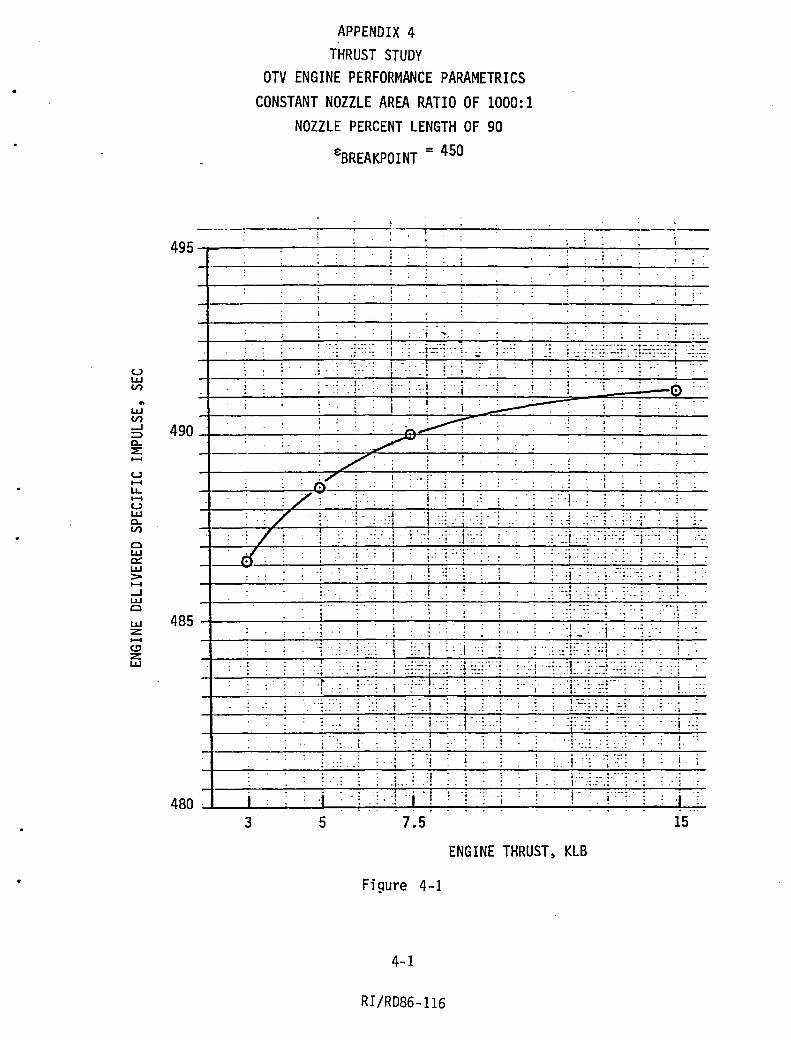
•
U I.JJ V) .. I.JJ V) ...J => c... ::E: .... u .... I.L. .... U I.JJ c... V)
C I.JJ c:: I.JJ :> .... ...J I.JJ C
I.JJ Z .... C.!' Z I.JJ
APPENDIX 4 THRUST STUDY
OTV ENGINE PERFORMANCE PARAMETRICS CONSTANT NOZZLE AREA RATIO OF 1000:1
NOZZLE PERCENT LENGTH OF 90
€BREAKPOINT = 450
49S~~----~~--~~~~-------------r~~~~~~ . I
: i
, ... .:": :j .. j''::'.:. '1. _ • ,.
. . ., . i . ,;:. j- .. : .:.j .: .;j. ..~ .1
I : ~ , i :~
... - . . . ,
490~----------~--~:~8~' =~~~;~~~--~--~~--_.~ ~;
-----------~~~--.~:~--~---.·l--~------~--~~.~.--~---
., J
! .:: '! i·: J .• , . ' ,/,'
:1 : ., '-:'.:.::- .:
i ". ,
.1 . i
:." . i I·
. • • .. .•. •. - :. - ~ .• 1
. -!"::: .. ~ . _ .:. 1 .. : ..
;. :! : :, :. '.:.:; .. : :::.1-.: ,!.
'1 .. :.".: ,. . .. I·
...... ! . 485 ~ ______ ~~~l' __ ~~~ __ ~' ~~~~~~'~·7::~·:~:-·!~~~-r--
. ! .: .! I . . -: .~! .. -: -i'
. ·:·i .
. 1' !
•• ··4 .- t· •
: ..
. i
:
j ·1
, ,.
: :.::·1 .. : .: .: : .. , . : .. i _.: :.: 'j
. ~ ! : :. .: ·1 .: .: : ,.1
.. ... .. t,·· • . . :! '1 ~ ... ~:
:', I
... -. -... . T ::: . :
.. ," -. '........ -.
: !
! ...
. I
480 ~ __ j~'~~ __ ·Li·~~.·~:,~:j_":~··I:_:~i ~·_'~l~~~i_.~~(~~I_. ~'~~'i~' ~ 3 5 7.5 15
ENGINE THRUST, KLB
Figure 4-1
4-1
RI/RD86-116

a::I -' .. I-:I: ~ 10--4 lLI :3
lLI Z 10--4 ~ Z lLI
OTV ENGINE WEIGHT PARAMETRICS CONSTANT 'NOZZLE AREA RATIO OF 1000: 1
NOZZLE PERCENT LENGTH OF 90
, €BREAKPOINT = 450
400~----~----------~~--7-~----~--~~~~.~
300
200
, . ;
". ../ : j',
, .. /. ; L· .. ·
;L /
,., •.• ~/ .. :_: 'J
'iV·: .. .. /':
: L:: • : 1
: ':. '1 .. ... ... . · .. .... ..... ... . .. .- ._. .... . · -: '-. '~;J :-; .... ~::: t. ~ . ':
., . ....a .... _ • · . --t. • .-. . J .. .
4 .
: . : .. ~ : .: .! . . : ' ....
','J .. : J .: : : "
L: :,1 ; '.:: '.j ::.:' , .. ~ .. :-:i':~:- i '~_:.:.! . , :'L
. 'v
! 1 :: 1,: 'L::~:· i .. ~-::",; ~.:
Figure 4-2
4-2 RI/RD86-116
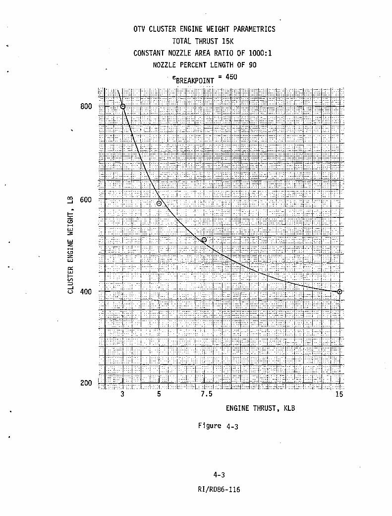
800
~ 600 ..
I:I: <.!J ...... LJJ 3:
LJJ Z ...... <.!J Z LJJ
c:: LJJ lV) :::::l
d 400
200
OTV CLUSTER ENGINE WEIGHT PARAMETRICS TOTAL THRUST 15K
CONSTANT NOZZLE AREA RATIO OF 1000:1 NOZZLE PERCENT LENGTH OF 90
£BREAKPOINT = 450 :~: :::E\- ~::T: f::::d ~:~c·>~ ~~=-X:~::::~~- ~::~ ~~::; ~fj" ~~~ :~~ i~~F~-d~;~ ~n~:~t~: :~~~2:: ::: :~-:::1~) :~}:::i~:: ::~i::':::::~ :::J.;'-: ~-:q;:-.: :.:~: ~-~- ~:~ ~~~~ ~~: ~;kJ:~:: ~~~j~:J~~: ~::~::: __ _ ~:: -~~:~;- j\:~:l~:: -::-:j L:e: ~:~ ~:~~ ~::~~~ :-:=T~ ~ ~:::~~:~ :~-::~== ~;:=-:f:.:-:::r~: ;::T< ~i?~:~ ~:=-~:~~: ~: :~: :~:~F: Xr-:: : ::~rJ:~:~:~::~ ::J:~::;.:~q::-::: :~T~ :::::: :~ :-:~~ ~~:: ~~~ ~~~J:~t::V,-;- ::~: J~~ :~i: :::~; -: ~:: ::::j:~J:::~:~::t:J:_:: ;;:::;:: ::~l~::~;::~f':-:: ~~: :;:~ ~:: ~i: :::~·~~Jc:~;j::~:;~J::~l~:~-:P::~:: ::::: ~: :-:J~;~~1\;:L~:-J:-::::::l::::: >r-::j:::l::: :i._ ::::~ ::tfj:: ::i~1:~:: ::::1:::: -:J~~r:::-: :::: ::': -:~:::~i:::: :-,:j:\ j=';: :~: ,: J:~:~ ::ji;::t:~:]~.=.: :::: :i~ ~~~:::~~~:~= ::;;: ~~::::t~+:::::!:~~: 7::: ::,:J~:-: :: ~ ~3":::': ~!::c.,:~::':1=-=~ ;~:: k:: d-=:¥== ~ : __ ~;;;g; ;;:: :~~E.--=t':.:: ~=r~~~_ ~=:= ::::::h~:-: :. ~i ~,:t~,: j,-'::::~I\Y~ :::;1~~ ::=:~!~-~::=~~t~ ~~ ~~ ~~~~: ~;::t::::: ::~f~~ =~~i~::~:-: :~~ :::q~::-~ :~ :~ :::=L>:d:::~\(;: ::;~C:-: -::::lLt~~-J:~; :::~~ :~~~ :~-r-=2: :i-~==j:::c:~~c::;;T:: :~~~ =~.: :'::i[:_: ~:: .~:y:;,:==~;~:: ::::~V :~~r~::~~:!:::~!:~j':L=::~~:~~ :;~~.~:::~ ::::-:t::~:=~~;:~:i:~: :~::f~:~~ ::~:k .. ~ ::~7::::::·-:~:i:'4;~~;:X~:j~:: :~:- :::: ::'r::bA~~~C: ~~~ .•. :~:r:-J::T'::~~:L~{":,T:~CT:: ,.
::.: .:--: ,~~+-::;, -;t-~'~):.:·. t~ 1: _ .:'-:' -l.---r;:-'I-;~~:-D;l:_:;;J--~~ -f-~~-1-----j ~~:-;~~-1n:i:_~~~:Ti;.li:--,I •. ': I • :::~:~'::i-':::k-l:~ J::~t:c':~ .--'~K.::.' :~:~:r.~:+:,:;r~~~ ::~l:C :~:~f~~t-=:'::~:J::;::l:~:::~:~:r:<;,j:··:
" :::::::c:1:~:;:::::k~:W:: -: .. ::::+:-K->~:l:-~:J~=-!~:i =~~T~:: ~~:~:~:~VC!::::I::~::r~~r~::j::::-: ~~:,:1:::: . :~: ::~~r:r:T~ir:::::: ::::j~[::~-=~-::'-l:~::':C:: :.::::j:::::J'::'~:~:T~~~:~:~L:~L:~ :.:~+:: . ::-: :~_~C~,:~:;~:: :::,!=: 1 ~~J:::, :~:~~' ::+:~X>K'= :~:: ~~:~- :~':-:::~~:::l~:~T:: ~=:~"~:1::J::::-i~:=;IC;d::':J :~: -:-=!::~f~:j~:L::~i:: :r:::j::::~.:.: ::~;::~~t::: ~~j~~:~,:~: '-=B~r:"::;:~:~.t :::l:~~I:~: [~~-; ::'1~: , .. ';':1' ,:f': ::""!. ,., .:::-::::". :;:--:n~:::i:::r::,::=:::0':t)-~--:L:::r:t·:Cf·~>~ :;:'1:::] .
'., :;-:j:~'- I: ::: ~._:::: __ t_:F:;· -._~ ~;_ :;' '::: _::; ,:,-l:-~J':- _~- \~:L.:-~~,:-,I20D-' '~1-;~ ~ ;,: -1. ::: :.:: ~;j::;:1::.1;': Y::l::L ::!:=:X:::l::::;::;: :.::; ~:.~ :::~F= :.~ :::;~~:~:,~::,: ~>n-::0:::~ : ;A<r > ::;::~::,:~~:'J'T:,: :;:~r>·.uALkI:::::::+~::.:. :;:~t> :~-~.: L::-Y:-:\;~TJ:::J:~::b-: ::~~L~:l' :~: ~j:~:--k:T:l:J:: cd: :j::;T~,i~:=J.:::: ~:::I':-= :::::;1:::i: ~::: c:~ ~:::-1-:,:ct~+:~:l:~~r~, ::::::-::t: :'.::1:::: :::I:l-":~' :let ::l:::'-:C:Y:~ :i::f:: ~:=.-:~r::~ ~::: ~::-: ~:::!~::J~:tH::;:r.:~: ::: :-,:: :,: ::i::j::-::;::_i_:;-; :1-· !:~i,: [':T, :,:T' • :~:~':.:Tf:T~l:::~::'~ <1::~F:L:~r<:::' ,. : -:::::::::-:' (:! : I::j::::i::.!:r:t_::t~~:~~~~: ~::~:~::l:::+:::::i~I-'~[~:J~r,: ::~::.:~~: :-
': ,:_;;~-: ::,-:-:;;:J8<;:;:':~-;~i<,;,,:-w--r-,'ki; ':~~; _-;~ t':~ :id:-;t-:: -;;~;~i:~Tm~/1-Wf~ -:::-:].-' ':;r":Li_: ::-:;';.+':1::;:1::: ~:":.: ~:~~~~::,~i: ~::~ ,,::;r:;-::(l::':--l::: ::;:1"::'1 ' j::~~r:: :;~T>' :·'.r:::::}: ::A~~: :::T::r:)~~~:::~::~::::;-~ :-:~-~ ::~:Ll:)~~: :::~ ;~~ ,::1":; .. L: :~:+:, ·:::L,-.l.:::L:; ,J::+::!:::L:+:::I::~J:=: ::l: :;:. ::::1::> ::=L~-:I:::0-:L::I::;: ::::;::T:
3 5 7.5 15
ENGINE THRUST, KLB
Fi gure 4-3
4-3
RI/RD86-116

co ....J .. z: .... ~ CI c::c o ....J >c::c 0...
o L1J t!J
I o l-
I o L1J ....J
OTV PAYLOAD GAIN PARAMETRICS CONSTANT NOZZLE AREA RATIO OF 1000:1
NOZZLE PERCENT LENGTH OF 90
e BREAKPOINT = 450 400~'~"--------~--~~--~--~--------~-7--~--~
- --'--"--"-~-------'--~------
-----.-----~-----.~~~~---------------'----I 3001-~--------~~~~~~1~-7~------------~--~---
.: i:":,/;. ; ... ; .. 1 .. :. ::: :':: . ... ,.., ,., '. 'I .... -_ .... ~ "
,- .... · .. . 1 .•
'.~/: /; ;: l.:~:~l·::. i' I· ~~~.~fr-/~'· ~~~~.~.:~. ~.~.~.~.~. ~ .• ~.~.--~~~--~~~~-----
: .' .~: i" ;': ':! : 1 . ... . ... -200 ~--~~~~~~~~~~~~~~~~~.~------~~ :1/: :/. ;'!.' i : ·1 :.! ..... ' ;:: .: . . , ... . - . . .. . -~, . . . . . . , ", ... . :. :-:.. . .: ::.:
. "" ...... -~. . ..
-300 :~. ~·_-=··t1.=-_·...;.;·.l~·~~;.:...:-;·:;_:"",,:·"~....,.·:~::l_·':~:~·:-+·l...;.,'-::~';-:;<-+T_;:.;.;.:i·....,.'--:+·!·~::';';"·~ _ . ...:...1 __ .......:...: _":...' _:::....._::.... . ...;.;:.::.;.. .. ...;.; .. ::.......;.;:.......;.;--.;_ '. '.l" '. .;. :.' .1,. I. :"; '::!., .. ::.' .. :l· '.:_.',.:.': .. ' : ."; . .: ".' ·r·! . ~ ~:::::'-.'~ : .. : : . ~~ .. " .• '.1 l
' " .. · -0- •.. · .. -.. " . . ... - .
-400 . . . ~: , GAIN DUE TO ENGINE PERFORMANCE
~ I :.1 :; ':';H~'::l ~ .. :-t~LJ.· GAIN DUE TO ENGINE WEIGHT , . - , ..... ·1 .. '1 '" .. '"1'''
I· ---'-~; I~-'~' '~:--:-':-7T-=:-"<+-; ~:-:-,'~ ::-:-,-' : .~: ;1-"-;' -:-' ~ .7.. ::E~-:-:::~1.=;~-+T.::....;.' ': NE~. ~A ~ N . :1·:'·: .j .:.: :1· .. :; .... 1 .• : .:
-500 :1 ....
i. 'j ..
f i "j ~. l . 1 : .:~ .:';:; :\ -600 ~I '---..... I"-~~~'. :_.·...:..l_·...:..l·....,j···il....· ..... l_ .. ·:_' ·...;..1.-;....: _~_....;....---.....;.. __ ~i'::--
3 5 7.5 15
Figure 4-4
4-4 RI/RD86-116
ENGINE THRUST, KLB

2500
2000 <C ...... V) a... .. LLI 0:: ::> V) V) LLI 0:: a... 0:: LLI co :::E: <C :I: 1500 u
.! .. j ..
OTV CHAMBER PRESSURE PARAMETRICS FIXED NOZZLE AREA RATIO OF 1000:1
NOZZLE PERCENT LENGTH OF 90
: .1
1 I '!. ... ,.
! .
= 450 EBREAKPOINT
i i
I. I , 1 ...
j I ,
.; i ! ,. J 1 ..
1 ,
: ..
i"
, :
~ .;. ,) 'j i~::i . -, 1:;
::l . 1 .::< :~;':: ::::j:::: ::'~~: ~. ·::j·::l.::~~::l:::~··i :'y::):=::X- :<·;:].:::1.:1.I . : : .! .. ., :':j:;::: .. L .. ::J':~:~J-~ :·:jU;(> "! .;' :1: ~ .. -" .. ,
: . :1 . ! j ::;: -i····!. "1'::;:.:1 :: y.! ., i
I ! :
.1 I ..
I. :'. l "I' I : .. / .'. t •. • ,.
:! .. ·:!.l I' ,. .:,::':. ,. ;"/. , .
.:: ::;:::; :: ':_:1"-:: .>/-: ;:T·: l:<-i:j·:::~::~:L:~·~:.:r::T =J:~;:: : ~-::i::::T')': j :! . l' : : .. '~:::V->,1 l::;,/i\<:': i:::~:Y~~i~:"l:::c~·:-:J:::i: :X:;:;' :::}:J ::=!:".:: : '::1·. 'c'·::c.'j- :i .:01 :r7~:.:j::::;:·I·:·'i.·Y::~;:~:;·:::X~:t ,::l' ::1 ::~:,:::::::l::Y·T::C.J ··c.:: .:i:::Y;:i ,:: :">:7'::]'::1 ::~ ·r::::::~:::::~:-::j:;':;::T·:::::-L:i::, ·:;::c:~r::;···:-i ~;;::; :;. :'h::l:::!:;::l!::~: :::): 1::,; .: :~::F-~l::::~:~:~·:~~~::y~:!q;,:~::~c :~-·J:~:l~::;-::l':;~~ ::;-:r: ::>:l.+~ ~.J:C: :::l:~: ::.~>- ·::T;:~F~~:==T~:i'~:~r::~1:~;l::;1:-::.~::T~T~:~r:;'~i:::~::· r-:;; :' .; <\ :::~Ji-' r~: ~:oj ::: :::~ :.I:::~:::T:·:~~:':±:::T:.J::::!< i:"~: ,::::;:::.\ ;:ci .. 1 :.::j "1.
__ :. k::/:: :-,fJ .:T::::::~ .:. ·;:·:;:'4~:~::~1:~~~_:::J:~:i~U:::~,:J::J~<:!:::~:~·! :':;:JJ: -':i',:Cj:]:'::'t:: '::;.':: :-:.'1 :·:L:l:~~~:~[~:;i:T::X::i :: ;.: 'I :'~:~:T;j . : _c'; ::lc-:: -'. : ... ' Ii:":' ::1-':": 1::: :,i :J:::~~<L_~i::::::i::! ':1 :: -:IJ::.l:::i !;·r
, .t:\ -;" ... : .... :. :::.;- :. '::::::.:1' :::':'::j-:_-;:::J.-::.::.J" ,. :-j.:::;-.:., .... '.'-.1': · .. ·.1 .~: .. : \;I.::~~::-: :~~.;:_~_ ,::",1. :. -. :- ':-.:~:=::' ...:-:-~:.~-:J·~-:.L··- :~:: -:": • .. :'::: .. ~.:-; . :-,. :;
ENGINE THRUST, KLB
Figure 4-5
4-5
R I /RD86 -116

Vl LLJ :I: U Z -.. :I: l-t!) Z LLJ -I
LLJ z: -t!) z: LLJ
OTV ENGINE LENGTH PARAMETRICS CONSTANT NOZZLE AREA RATIO OF 1000:1
NOZZLE PERCENT LENGTH OF 90
tBREAKPOINT = 450
200~------~----~------~------------~~~-.--~~,:
150
100
~ :
! -::- ~J 7::--~"~: ... -. I" : . ,.
0' • ! , !
. , , . ..J •.• _;
-. -- ... -.. . -. . . - --. -
.. 4 ':", " ••
i ..• . . . :: -:':... ... . !' . ~ . , :1
: i
. 1 ... - -:~:- --: . • 1 -~ -:;~' __ .: .. j- . ~ _... - -: ··1- ~:.j. ; ',·:L ~:.'.
+---'--+--:..~~-7---7.-_.:....:. ..:.r, j-::: ,~.:4, .::-:-': ,-:----:---~_:___....;..;...~....:.- , :~.. ...... _, . . '} ... . ..: 1:":. • ,,: .. ;"':' :~ :::~: ::':::i"',:,1' ':,
-
:(!)~ ,I
-
'j
..
!:l':'!~;~· ';': :~:
" : ~ :~ .:
• - - -t • • - • • -,. t _ .•• : .. :' ': ": 1 : :
I· ·i· - ... '0- - -': " .. - ' , ' .. ' , . ' '.-
~ .' :-.:' . t" - : . : - : ~
'. ' . _.' ..... . _. - ...
! . ,
~' ': ,i '''j ' ..
"
-, -. -.
I,
: !: i "~':~ ~::j ",! ,'! .. :" • '. • t_·
:. .. ~ : ::~ -: - :; ". .~ .. :
. .. . . -,
~ ':', : : 1 . : - . ~ .
... -... --_ .. .. :! :::: .. :: . --:: ,'.f ... ' ~ ...
! "': - ~ --; .'. .; . •• • -. 't' -.-. • .... , .' .
• -t' e_
: .. I , .. , , i
I
I .. I ·i
i ! 50~~~~~:i~' ~'_I'~'-_'~i_"~:~"~' __ ~ __ ~~~'~~~:~l~ 3 5 7.5 15
ENGINE THRUST, KLB
Figure 4-6
4-6
RI/RD86-116
,>-

V) I.LJ :I: U z: -.. 0::: I.LJ II.LJ ::E c::( -C
I--X I.LJ
I.LJ ....J N N o z:
60
40 ':"
I
OTV ENGINE DIAMETER PARAMETRICS CONSTANT NOZZLE AREA RATIO OF 1000:1
NOZZLE PERCENT LENGTH OF 90
EBREAKPOINT = 450
': . 1 .' .~. "i .':1. ' .. •••• 0- j":".:' !
J'
..... l'
i . : L j ! " , . ,
: ! i .,
'j '" y: .
: 'Z , , ,
! : " ;
/' , ; ;' , '!
:/
:",
.. ~ "I ...... "0 •••••• -.
J. /,.. :,' i : :,,' ,:: .. ~:, '~, 'J,::::'::: '
" ... . , i ': '!":', ~ ,,',:' "
t " : ,., : : i 'I : ,: :1 " .. ........ , ;-,j :J ,. t··· ' , . ,
' '\ 1····
: 1. \ 1 i .!: ... !: "
3 5 7 . 5
,I'
,1: : /~ , "V :/ y:
j "
··f ,,, i.
-., .. , ,
, " : J --':" '"
,': "I . . . ~.. . _ i : .. t
,'::1 "
! '
; ,
q :,~,:,
.: ',,:,' '. ' ','" .. --:' I :,,'" : :j,: , 1 .. c: . "
, '\' ,; : " I, ',_
i ': __ '"j ':
,I __ , 0-1 ..
15
ENGINE THRUST, KLB
Figure 4-7
4-7
RI/RD86-116

.. >u z UJ ...... U ...... I..L. I..L. UJ
0.. ::E: :::> 0.. o co a:: :::> t-
OTV TURBOPUMP EFFICIENCY PARAMETRICS AT CONSTANT NOZZLE AREA RATIO OF 1000:1
AND NOZZLE PERCENT LENGTH OF 90
EBREAKPOINT =450
70-r~~-7~~~~~--~~--~~~~~~~~-:~··~·i j .1:. l·" to
'j I
J "i I
, , i'
• \ . ~ ! ; i. i . , . i j
50
:. :. i .: 'j-:,; _. i ! -:::J: .. - -I· -. ._, i :-'.! .. : ..
• ,. _l.
--0- : .. -:- .: .. _. I .. .. ,. . ':: :::.J '. :.:_;
':i' ~::l<:l :: "1' :-:' : ;"i-::;:::' '.+::: -j • .., l:-'C .:J ... 'ceo ; -t:7+~+7+~+:-:-~~'~-=---+~~~~~~-;"'~'='~":-~" .:-.j:- I 40 .1':.:::. j .::J. . '.:::1::::":- .. . ... :.:_ .. • .·1; -_ l_.t . : .. I~
3 5 7.5 ENGINE THRUST, KLB
Figure 4-8
4-8
RI/RD86-116
15

..
OTY FHEA
SYSTEM: Turbine and Turbine 105 ITEM NO.--..QL NAME: High Pressure PIN REVISION_O_ ANALYSIS DATE: 12/84 PAGE_l_ fF_l_ Drfve Systems Oxfdizer Turbine
REF. ICHM OR OTHER RESPONSE CRIT. Cil NO. PHASE FAilURE MODE FAilURE EFFECTS FAilURE CAUSE MEANS OF DETECTION TIME NO. ITEM
050301 PI, MS, Performance Controller will fncrease Increased tfp seal clear- Chamber pressure and Adequate 3 TH, AB degradation f nl et pressure and gas ance, gas seal wear. flows mixture ratio
flow rate. (algol, torque-meter.
050302 Same Same Devradatlon exceeds avall- Same HPOP discharge pressure Adequate 2/B ab e power reserve. below minimum redline.
050303 PI, HS Excessive vibra- Progressfon may lead to Turbine wheel rubbing Accelerometers, ffber- Adequate l/A TH, AB tfon fragmentation. or Imbalance, bearing optic deflectometer,
::0 wear, prolonged operation torquemeter; Vl
....... at critical speed. - redline exceeded. ~ ....... 3: ::0 050304 Same Same Reduced power level Same Same except redline not Adequate lIC "'l:I CI r- ::t» 00 01 operation alleviates exceeded. ~"'l:I 0'1 I problem. "'l:I I ...... '"T1 ~ ...... 3:3 ...... 050305 PI, MS, Turbine blade or Progressfon may lead to High cycle fatigue, sur- None Inadequate 1 X ~ CI
0'1 ~ ...... TH, AB, wheel fanure, uncontained damage and face cracks, contamfna- >< SO fan ure of sta- fragmenta tf on. tfon. a
c::: (,11 tfonary part -I Interfering with "'l:I
turbfne, housfng c::: fanure. :-l
050306 ES, THI, lOX from pump and Ffre - major uncontafned Excessfve seal leakage, Seal purye pressure Inadequate lH X PI, MS, turbfne drive gas damage. and failure of fnter- failure s mandatory TH, AB, mix. mediate seal purge. engi ne shutdown. SB
0026d(14)/emh

OTY FMEA SYSTEM: Oxtdtzer Feed Syste. /06 ITEM MO. --.!L NAME: Low Pressure
IIxJilher PuIIP PIN REVISION_O_ ANAlYSIS DATE: 12/84 PAGE_l OF-L-
REF. ICHM OR OTtER RESPONSE CRIT. CIL NO. PHASE FAILURE MODE FAILURE EFFECTS FAILURE CAUSE MEANS OF DETECTION TIME NO. ITEN
060201 PI, MS, Perfol'lllnce Controller wtll tncrease Excesstve clearances or ChUlber pressure, flows Adequate 3 TH,AB degradaU on. turbtne power for .tnor seal leakage, blocked and .txture ratto.
degradaUon. tnternal passages. wear, (Algo) eroston. cavttatton, low NPSH.
060202 Same SlIIe Degradatton exceeds avatl- SlIDe Dtscharge pressure below Adequate 2/B able power reserve. redltne.
:;0 ...... .......... 060203 PI. MS • Excesstve vtbra- Progression IUY lead to Rotatiny group rubbtng Acceleroaeters. fiber- Adequate 2/B :;0 TH.AB tton. significant contained or imba ance. bearing opttc deflectometer. OU1 co I dUIIge. wear, loss of bearing torque-meter, redline en N coolant flow. prolonged exceeded. I ...... operatton at crtttcal ...... speed. en
060204 Sallie Suae Reduced power level opera- Same Sa .. except redline not Adequate 2/C tton allevtates proble •• exceeded.
060205 Pl. MS, Excesshe speed. Progression IUY lead to Cavttation. abrubt Tachometer redline Adequate 7-/B TH, AB, stgnificant contained reduction in load. exceeded.
dalllge.
060206 PI, MS Piece part fatl- M~ result in signtftcant Htgh cycle fatigue or None Inadequate· 2 X TH. AB, ure of rotaUng contatned damage. surface t.perfectton + SO group. beartng fattgue. conta.tnatton.
fat lure. fatlure of piece part resulting tn tnterference wtth rotattng group, houstng fltlure.
060207 PI, MS, Internal ft reo M~ result tn uncontatned Rubbtng. fretttng. or None Inadequate 1 X TH. AB. dalllge. structural fatlure of SO tnternal parts (t.pact).
0026d/bJm
t-•

THI Transition to PI
APPENDIX 6 TRANSIENT ENGINE SIMULATION
PI I Mainstage Transition
to ~1a i nstage ~-'~~I~E--~~f~-~~~+~--~~~IE--~~~~
r
L
2-,
MA I N F1..EL VAl.. V£ POSI T I Q'>I {PERCENT! IOO.OO~ ____ ~ __ ~ __ ~ __ ~ __ ~ __ ~ __ ~ ______ ~ ______ ~ __ ~ __ ~ __ ~~ ______________ ~
OO.OO~~~~---4---+---+---+---r---r--~ __ ~ __ +-__ +-__ +-__ +-__ ~~ __ -+ __ -+ __ -+ __ ~ ~.OO~--~~---4---4---+---+---r---r--~--~--+---+---+---+---~~---+---+---+--~ ~.00~~~~ __ -4 __ -+ __ -+ __ -+ __ -r __ ~ __ ~ __ 4-__ +-__ +-__ +-__ +-__ ~~ __ -+ __ ~ __ -+ __ ~ ~.00~~~~---4---+---+---+---r---r--~--~ __ +-__ +-__ +-__ +-__ ~~ __ -+ __ -+ __ -+ __ ~
100.00
00.00
60.00 '+0.00 ~.OO
100.00 00.00
60.00
'+0.00 20.00
100.00 00.00
~.OO
'+0.00 ~.OO
o
o
I
I
o
---/1 , ;
.I
o
5.0 10.0 15.0
i , --.. ~
I ~
, ~ I
I
I
I 5.0 10.0 15.0
MAIN OXIDIZER TLRBI'I£ BYPASS VALVE f'U'.;17!CN (PERCENT!
I
I I
I 5.0 10.0 15.0
MA 1 N ox 1 0 1 ZER VALVE POSI TI Q'>I (POlCENTl
---5.0 10.0 I!I.O
TIt'£: (SEC)
Figure 6-1 Valve Sequences - 7.5K Engine Start
6-1 RI/RD86-116
I 20.0
; ;
1 ,
r I
I I I
I I I 20.0
1 I
; I I
I I I I I I I
I I !
20.0
I
,
I I 20.0

r 2000.0
I~. 0
1000. 0
~o.o
.I V J
V o
L
I I
r v
: . : .
• I • • . · I • ·
. . · · · . · · · ; . · · · ·
. I . · · · • I · • : · · ·
J i I
)1 ../
~ V'"
5.0 10.0 15.0 Tlt£ (SEC)
Fi gure 6-2 Chamber Pressure - 7. SK Engine Start
6-2 RI/RD86-116
85103101 OlV75<O
I 3-,
20.0
-1

r 1IlOO.0
6000.0
'+000.0
2000.0
/ .-• ~--o
L
~ ------
-
----
--r -------I
~
5.0 10.0 15.0 TlI'E (SEC I
Figure 6-3 Engine Thrust - 7.5K Engine Start
. "
6 ... :3
RI/RD86-116
85/03/01 OTV79<O
i I
I I
I I I
I 8....,
20.0
..J

r 8.0000
6.0000
'+.0000
2.0000
•
• . . . If···
'.-.i Q
L
~ 111X1"~ RATIO (~l
I I I ~ V'~ I I ~V
. . ~
,
~ · · · I ""-~ I
1/ 1.1 . . . . · · · • .
- V I ........ """"--l
/ . . . . . . I · · •
# . . .
I !I.O 10.0 1!1.0
T1I£ (SEC)
Figure 6-4 Chamber Mixture Ratio - 7.SK Engine Start
6-4
RI/RD86-116
as/03/0t OTV75<O
,
I 9-,
20.0
-1
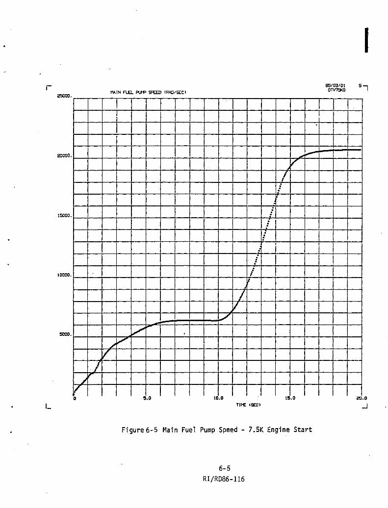
r 25000
I
20000
15000
10000.
5000.
,/
V 7
~" v o
L
I
~:.--
V-/ . . .-
f . . .
I : · · · · I . .
: I 0
I 0 . I . · · · · . . i
I
/ V
./
'/ Ii"'" .
V I
:i.0 10.0 15.0 TII'E (SEC)
Fi gure 6-5 Main Fuel Pump Speed - 7.5K Engine Start
6-5 RI/RD86-116
! .
,
I I
I
95/03/01 OTV75<O
I
i
I 0
I 5-,
20.0
...J

r
L
t-1ainstage
-1 =+=
100.00
so. 00
60.00
'to.oo
20.00
20.0
100.00
BO.OO
60.00
'to.oo
20.00
....
20.0
100.00
80.00
60.00
'to.oo
20.00
20.0
100.00
90.00
60.00
Ito. 00
20.00
20.0
" ....
Shutdown
PV.IN F"l£L Vo\LVE: POSITION (PERC(NT!
t . I .
• " 0
"
". 20.5 21.0 21.5
MAIN T~I~ BYPASS VALVE: POSITION (P(RC(NTl
0" "" 0
0
0
I
, I
20.5 21.0 21.5
MAIN OXIDizeR T~BINE: BYPASS VALVE: POSITI~ (P(RCENTl
20.5 21.0 21.5
PV.IN OXIOlztR VALVE: POSITION (PERC£NT)
" -. .
• 20.5 21.0 21.5
TI~ (SEC)
Figure 6-6 Valve Sequences - 7.SK Engine Shutdown
6-6
RI/RD86-116
I ...
1 0
I
J J I <2.0
I
I ! i I
I J 22.0
!
I
22.0
I I
22.0

r 2000.0
•
1500.0
I I
I , 1000.0
I
500.0
20.0
L
'. '!
OW1BER PRESSURE (PSI.)
I
I
. I . I I
I i I
I • T
I I
•
I •
•
I
I
! i I
I I
I I
, I
! I
I
I
85/03/08 OTV7SK1
I 3-,
.... .... ····f····l ...... .. .... .... I •••• •••• •••• •••• •••• • ••• .... ... 20.5 21.0
111'£ (SEC)
. Figure 6-7 Chamber Pressure - 7.5K Engine Start
6-7 RI/RD86-116
22.0
.J

r 8000.0
•••• .... ...
6000. 0
'tODD. 0
2000.0
20.0
L
ENGINE THRUST IL8F'1
i
I I i . I
I
I
.... ! I I I
I I
I I I
I I I
I I
I
....
. .... .... .... .... ... . .... .... .... 20.5 21.0
I I
I
!
I I
I , I
I I
I
. ... .... ... . 21.5
I
I
85/03/08 OTV7SK1
I
I I
I
I
.... .... .... ... 22.0
..J
Figure 6-8 Engine Thrust ~ 7.SK Engine Shutdown
6-8 RI/RD86-116
A

r 7.0000
6.000 o •••• ....
s.oooo .
•
'1.0000
3.0000
2.0000
1.0000
20.0
L
CHAMBrR MIXTURE RATIO I NONE I
I
I i
T I
I
I
•
. . ... . .. . . ... .... .... . ... . ...
20.5 21.0
I
j
.... . ... . ........ . ... 21.5
TII£ ISECI
I
....
85/03/09 OTV75K1
I I
I
I
I
.... • •••
Figure 6-9 Chamber Mixture Ratio - 7.SK Engine Shutdown
6-9 RI/RD86-116
I
I
I
,
I
I
. .. 22.0
..J

r 200000
••••
150000
100000
50000
20.0
L
PIA I N ~~L PUMP SP£ED (RPt11
••••• . I···. • I
• . • . .
I .
I . . . . I . • I
I • • . ." I . " . I
.. . .... .. • I . . .
• . . . . I . I I I
. . • •
I I I
. ···l I , ,
I I I . I I .
I
20.5 21.D 21.5 TIl'£: (SECI
Figure 6-10 Main Fuel Pump Speed - 7.SK Engine Shutdown
6-10
RI/RD86-116
I . •
85/03/08 OTV75K1
I
I
I
I 1
I I I
I
I I I
I I I I . . I . . .
I 5-,
l·· I I
I
I
I 22.0
-'

r 70000.
.... .... 60000.
I I
50000. I
I
I "0000.
I
I J 30000. : I
I
20000.
10000.
20.0
L
1141N OXIDIZER P\.tP SPEED (RPMI
I I I
"t I i I
, I I I I , , ,
, ' . I I " , , , , , , , . ,
" , I
I , , I ,
I , ;
, I
, I I ,
! I ! , I I
, • ,
1 I ,', I
, "1 i . ..
• • I ,
" I
..
, I
.. .- -
I I 20.5 21.0 21.5
TIP£ (SEC)
Figure 6-11 Main Oxidizer Pump Speed - 7.5K Engine Shutdown
6-11
RI/RD86-116
"
95/03/09 OTV75K1
I I I
i i
I
I 1 I I I I
i I
I !
; I
I , . , ,
I I
I 6-,
I I !
i ! ! I i
I i I , i i I
I , I --! I I
I , I
I I
! I
I i .. . . i !
I I
I I
I

'.

r
APPENDIX 7 TRANSIENT ENGINE SIMULATION WITH TSV
MAINSTAGE SHUTDOWN
~~f~---------------~,
100.00
80.00
60.00
-ro.oo
eo.O&
20.0
100.00
80.00
60.00
..a.oo 20.00
~.* ...
20.0,
I I
••••
nHIN FlF..l Vu....VE POSlTlON (PERC£NT)
1 ... I ••
I itt" I ~. .. I , tt .. f ..
" .. .. 2&.S 21.0 *. 21.S
MAIN TURBINE EYPASS VA:"ve: POSITION (PERCENT)
.. " ... .. " .. It
2O.S 21.0 21.S
MAIN OXIDIZER TURBINE BYPASS VALVE (OTBV) AND TURBINE SHUTOFF VALVE (TSV) 100.00 POSITION (PERCENT) 80.00
60.00
-ro.OO
20.00
--- ~ ,..,., ~
"' ,
.... .... ....
e-,
I
I
I . 1 f
I 22.0
i I
22.0
IOTR
.0 20.£0 " __ 1._ ~_. __ ~_.~_'--__ ~ _ 1-_. ___ .J..I~
21.0 21. 22. o
100.00
eo.OO
60.00
40.00
20.00
eo.O
MIN OXIDIZER VALVE POSITI~ (PERCENT I
1*. • I·.
" . . -" .
• *. 20.6 21.0 , 21.£0
TIrE: (SEC)
Figure 7-1 Valve Sequences - 7.SK Engine Shutdown with TSV Located Demonstration of HPOT
0346/49
7-1 RI/RD86-1l6
22.0

r
L
2000.0
I.
i
Js.oo. 0
100(1. 0
500.0
• 0
I
! 't: I I , , I i I .
.. I ., I
I
I I
I I I
I ! •
•
•
•
IT ...... f4... ~~ • ........... f+... •••• ..... r+< .5 .............. 21.0 21.S
TIrE (SEC)
Figure 7~2 Chamber Pressure - 7.SK Engine Shutdown with TSV Located Downstream of HPOT
0346/49 7-2
RI/RD86-116
i
........
I
• •• t2.0 .J

r
• L
EHGnlE THRUST (LBFJ 8-,
BOOO.O
I ~···t·-t't····1 , I
, i
I I I
I j I ! I I I ! i i ! I I I I I i I ;
i I
6000.0 I I I I i I
I I
I I I I
I
-, I ~ ..... , I I
I ! ! .! -4000.0 I I I
2000.0
1-* •••
.... f. ........ f. ....... ftt ....... ftt ... 20.5 21.0
.... ~ ...................... 21.S l2.0
.J 20.0
TIrE: (llECI
Figure 7-3 Engine Thrust - 7.SK Engine Shutdown with TSY Located Downstream of HPOT
0346/49
7-3 RI/RD86-116

r
L
1. 'I'),') r--,---"l---;--y----.---,---r--.,-----,r---,---t--...,..--..-----.--.--.......--.... ---- I I, ! I ,! ,. ! ( I ,. I I '-I I
~~~-1 I I ; ! I ! Ii: 1 '. I-I~~II' --I--,-I,--!:--j--;--ill Ii. l -l-----J-----·il--.J:~· --!~-~. "''''f .. ''' .. ·· ; : I I : ; 1--t--1 ; : ; ill ! I
L I I I ! ~ : : ! i ~ ; ! ; t: l.!; i : I I I ! ! : : ; I I , I : f l i l i I iT! I ! 1 I I I r I ! ! .1 i '--U---l ! * I I \ I • I Ii' : . . , i : ( , t
s.::lGO OI -,----{--.J--l; 1--:~--l~_.-! __ l~~_-1--'_~--! I : t ~ ! f ! : ~ ! ~ ; !-, -~ t , ;
---·--f---!1·-·..J1~.---,-,--1--1-!~-1-----r~--·'=l--l--;-~· --1 '----J . ! i ! ! '---1 1--1 I I . t f ;~ ! ; l f ~ I ~ :~ i ----,--1 ----"1
I---.~----J-~--l I ,. -l-:~-----l i ,i :--J----{--L-+-J I . I ! I I Ii! , , !! . i I I / I ~-_l-_.J : : . , : ! ' ,_ ! : i : , . ! , : I
4.(,(tri(t~ ! I!, ! i r---' ~ i II I ~i I 1 ! r I I r I til I ' " r-:--r-, , r I I I •
3.'~0('; ; i
fES 'R I ( ! I I f ! ,
I I i i !
i I I ! I ,
i ! i . ;
i I I i
r I ! I I i
~ I
2.000(1
I
1.GG'l0
20 .0
0346/49
~ I : ,
i f
* , I I I
I , I , I I I
,
.. I I I
*
.. **10.\*** **** *H* **** ***11. *H **** f**W **** f**Yl.\It** .,*W H*1t ........
TIME (SEC)
Figure 7-4 Chamber Mixture Ratio - 7.5K Engine Shutdown with TSV Located Downstream of HPOT
7-4 RI/RD86-116
I i ! I
I I . .-
....... 22.

("
•
L
MHiN FUEL PUl1P SPEED (RPM) 2C'JOO;) ~ I rH .. t*Hl"~*<,l I I I I I l : j 1 i \ 1* I I LJ I l '.':'. --if---+ ,--1---+-,---1
;,-M--'l--t:-1 I I 1---; I I: !I I I ]' :-i j I ~ i to i 1--1 I 'I' I I . ! 1----1 I '-:10' : ! , i 1--1----1 I I
,
: ! ! I !~* ~ .. I: ¥ Ii I I !i I II I, j~ !-il.-JII ! lS000C! : i !, ¥., I I '.: i "-1 I --.J r---l--'-'-' ---;---!--I~---j '--J . ~
; i ! ; i I ~. I I : i i '1 II I' I j i ' i - i ! j j. : i ! iii i ! Iii .l
',' Ii· Ii i ; I I i 't ! I II' iii , i, i ' ! ! ; • j I, I
:1 I I r--i I j i ,-,--;-r-T'" I I , i j . 'I .. ~ ! '. ~ I : I' 'I i I
[ l ; [ ii-' '-1 I t~-1~ii!:','--iI:-!-I!---1-r--I,-"li-l 10t'(;('11 ': I iIi I ~ i ! i I I I
1r-ll--I!1~i--T!~Ir-~I--r-~-+--~4--+-~~+I--!~4-~,~!--~!~I
! i !: iii! I ' I I !
iii I I I ! I
EMIlO I~~ -i~-· .. ··t . I r-1 I .. -.....;---1._.....;---1-.....;---1 ~-~~ .. -:-i'* --+---I-~---I--I---JI-I I I ** ••
: * • Itlttl •
·"It. ** .. ~ ... "***
eo.S 21.0 21.S £2.0
0346/49
TIrE (SEC)
Figure 7-5 Main Fuel Pump Speed - 7.SK Engine Shutdown with TSV Located Downstream of HPOT
7-5
RI/RD86-1l6
.J

r '70000 ·
~ .. ---- ... 60000 ·
611000 ·
40000 ·
80000 ·
211000.
11000.
eo.o L
n .... ,.' • .,...
MAIN OXIDIZER PlH' SPEED (RPM) TS't7~
-- -- .. I
-.. --
• • .. •
I
--"<
-- • .. Itt •
• I" •
•• ..... ... ... -. ... ...
•••• 'M
' .... • ••• 20.5 21.0 21.6
Figure 7-6 Main Oxidizer Pump Speed - 7.5 K Engine Shutdown with TSV Located Downstream of HPOT
7-6 RI/RD86-1l6
!
I
I i I
!
••••
22.0
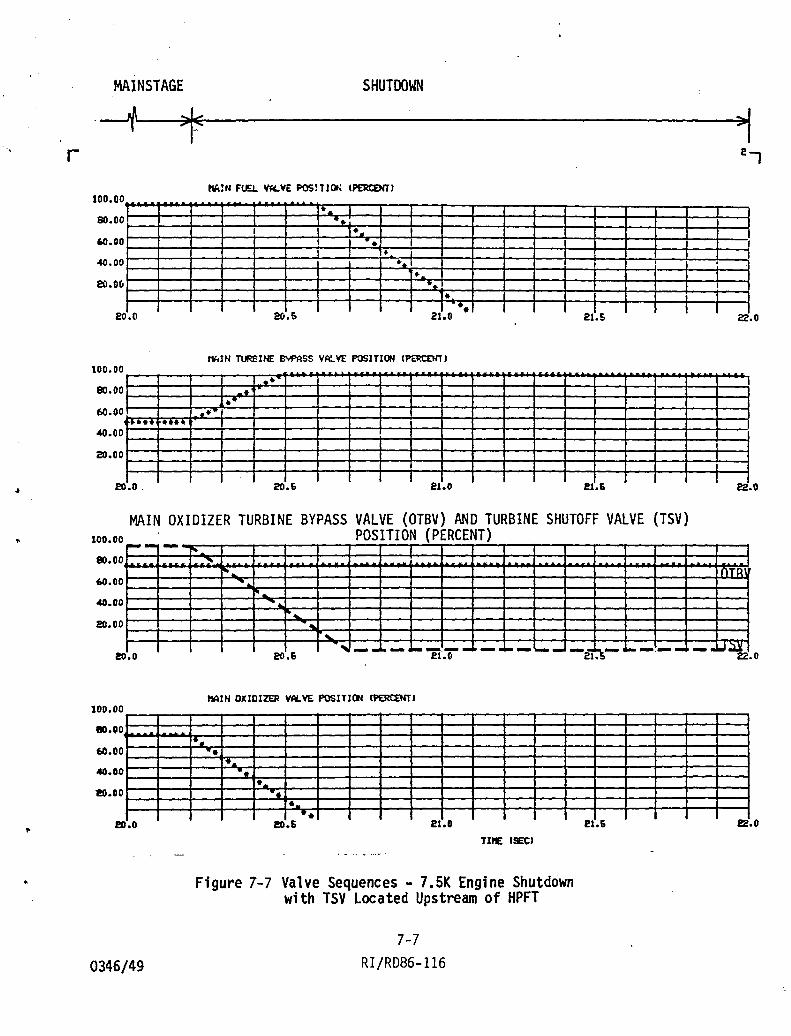
-. r
..
..
MAINSTAGE SHUTDOWN
·~~t--------------~,
100.00
80.00
60.00
40.00
eo.OCl
20.0
100.00
80.00
60.00
<40.00
20.00
r···· eo.O.
••••
ht.:N FtF.J.. Vf(.VE POSlTIOt\ (f'ERtEHT)
.. I -. I I *. 1
• I .. , ".1 , ,
.. .~;
• •• 21.0 21.S
I'IkIN TlIRSlNE BYPASS VA'~VE pOSJTION (P£RC£I(T)
". .. . -.,,+
I
J 20.& 21.0
MAIN OXIDIZER TURBINE BYPASS VALVE (OTBV) AND TURBINE SHUTOFF VALVE (TSV) 100.00 POSITION (PERCENT) eo.oo
60.00
<40.00
eo.oo
--- I' ,~
i"' ,
' ... ' ... .....
....
e-,
I
• I , I
22.0
22.0
nTR
• 0 20.6 '",- - .... ----.--21.0 ----'--- ---21 • _"-_. ___ .U~
220
100.00
80.00
60.00
40.00
20.00
eo.o
0346/49
~IN OXIDIZER VALVE POSITION lPERCENTJ
1*.
• 1-. " .
• -. • -. eo.5 21.0
TIrE: (SEC)
Figure 7-7 Valve Sequences - 7.SK Engine Shutdown with TSV Located Upstream of HPFT
7-7 RI/RD86-116
.
21.5 22.0

r 2000.0
•
•
1600. 0 1
1000.0
600.0
20.0
L
0346/49
CHMBER PRESSlRE (F'S IA)
•
..
I
! l I I
..
•
•
..
• •• ,. ... f.... !*j
• ........... r* ..................... ~ • * .............. 81.5 21.0 21.5
TIftE (SEC'
Fi gure 7 -8 Chamber Pressure - 7. 5K Eng1 ne Shutdown wi th TSV Located Upstream of HPFT
7-8 R I /RD86 -116
I
••••
I I
H. Ii.o .J

r '. .
L
'.
EJ«)U£ neJST (LBF) 8-,
8000.0
~ ... •••• f. •••
6000. 0
i
I I .... !
.fOoo.o
2000.0 I
f4t •••
.... ..... .... f*... '*, I~ .................... f4!.- •••• eo.5 21.0 21.5 eo.o .... .... .... ... 12.0
.J TU£ (SE)
Figure 7-9 Engine Thrust - 7.5K Engine Shutdown with TSV Located Upstream of HPFT
7-9 0346/49 RI/RD86-116

r '1.0000
6.000 0 .. •••
*H*
•
• s.oooo
•• 0000
8.0000
2.0000
1.0000
• 0
0346/49
CHAI'IlER rtlXTlRE RATIO (NOt£)
•
•
I
I I I
•
"
" • •• J!).''' ... -. ~ ... Ht ... • -zI .11~ .............. ~ ., ••• *.** ........ ***12 •
TII£ (SEC)
Figure 7-10 Chamber Mixture Ratio - 7.5K Engine Shutdown with TSV located Upstream of HPFT
7-10 RI/RD86-116
o

r 200000 ..... . ... ••
15000 0
10000 0
60000
20.0
L
0346/49
MIN F\JEI.. P\.W SPEED (RPI'I)
•• • • - i
- -.- • • - I -•
• • I I
•
-• • I'
• • ..
• • •• •• -. • •••
•• •• •••• r· •••
• ••• •••• ••
20.5 21.0 21.5
TIrE (SEt)
Figure 7-11 Main Fuel Pump Speed - 7.SK Engine Shutdown with TSV Located Upstream of HPFT
7-11 RI/RD86-116
.. J, TSVi'Sl~fo
I
,
.... .... .. ..
22.0
-'

r TOOOO ·
f+ •••••••
· :~ .
60000
. 60000 ·
40000 ·
80000 ·
20000 ·
10000.
20.0
L
0346/49
MAIN OXIDIZER PlJ1P SPEED (RPM)
• •
It
It
* .. It
•
• It
It • I •
• It
• . • •
-. .. -F •
•• -. • ••• .... •••• ~ .. ~~ .. * •••
20.5 21.0 21.5 TIrE (SEC)
Figure 7-12 Main Oxidizer Pump Speed - 7.SK Engine Shutdown with TSV Located Upstream of HPFT
7-12 R I /RD86 -116
~.1 '-
TSV7&K6
I
. I
I I I
I
..... •••• ' .... &.0
-'

End of Document