ntnu 26. mars 2012 sverre corneliussen senior system … · sverre corneliussen senior system...
TRANSCRIPT
Havbunnsproduksjon
NTNU 26. mars 2012
Sverre Corneliussen
Senior System Enginer, FMC Studies & Tenders
Contents• Subsea field layout & equipment
– Subsea structures & X-mas trees
– Subsea Wells
– Subsea Control Systems
– Safety systems
– Well flow
• Subsea Instrumentation, Vega example– Pressure protection
– Pressure & temperature sensors
– Sand sensors
– Multiphase meters
• Subsea separation

Subsea Applications

Topside ControlsTopsideProcess
Umbilical/Flowline
Production Vessel
Floating production ship
ManifoldXT
Bijupira Saleema

Snorre Tension Leg Platform (TLP)
Snorre UPA
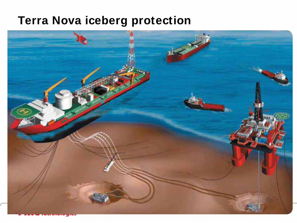
Terra Nova iceberg protection
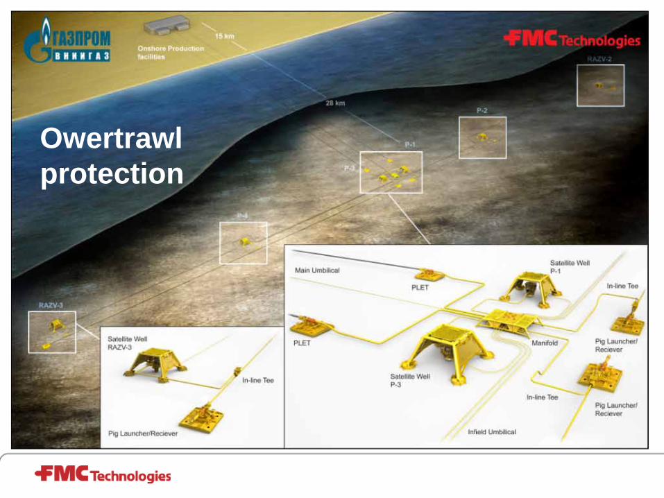
Owertrawl protection

Subsea to beach (Ormen Lange)

8 Slot Template System. Ormen Lange1100 ton
Suction anchor

Basic reservoar and drilling

Horisontal Well completion

Fishhook well

Wellhead system
13 3/8” CasingHanger
18 3/4” WellheadHousing
13 3/8” Production
tubingHanger

14
•Smaller production bore (5”-7”)•Production tubing installed brfore XT•XT can be removed without removing production tubing
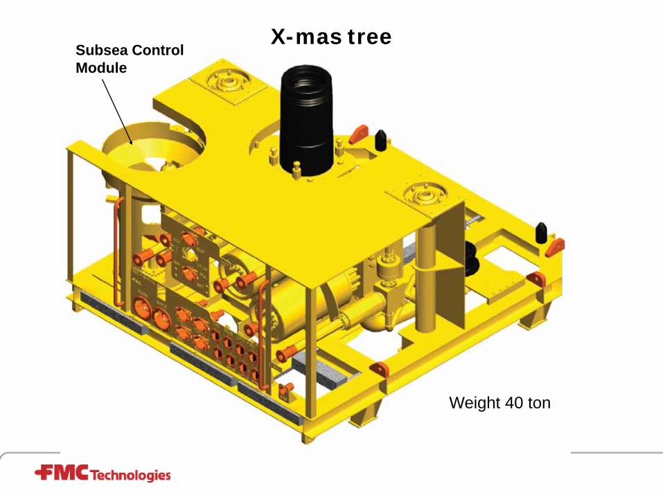
X-mas tree
Weight 40 ton
Subsea Control Module

X-mas tree
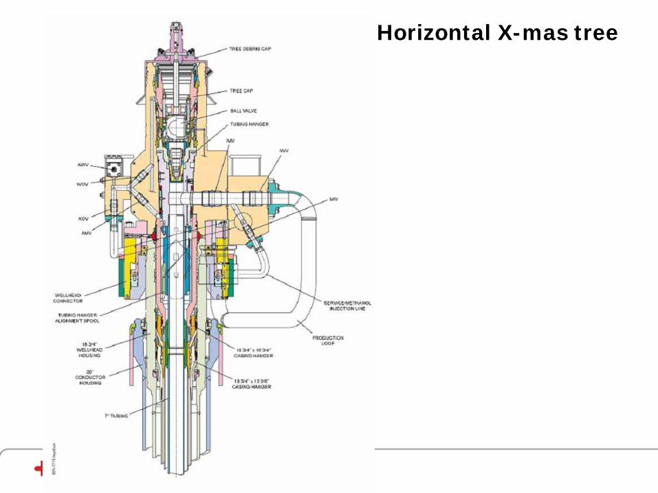
Horizontal X-mas tree
Subsea Production Control

Functions – Production Control System
19
1. Safety - Shuts in the subsea system in critical situations
2. Operator Interface during Daily Operation- Operation of subsea valves and chokes
- Monitoring of production parameters and system integrity
20
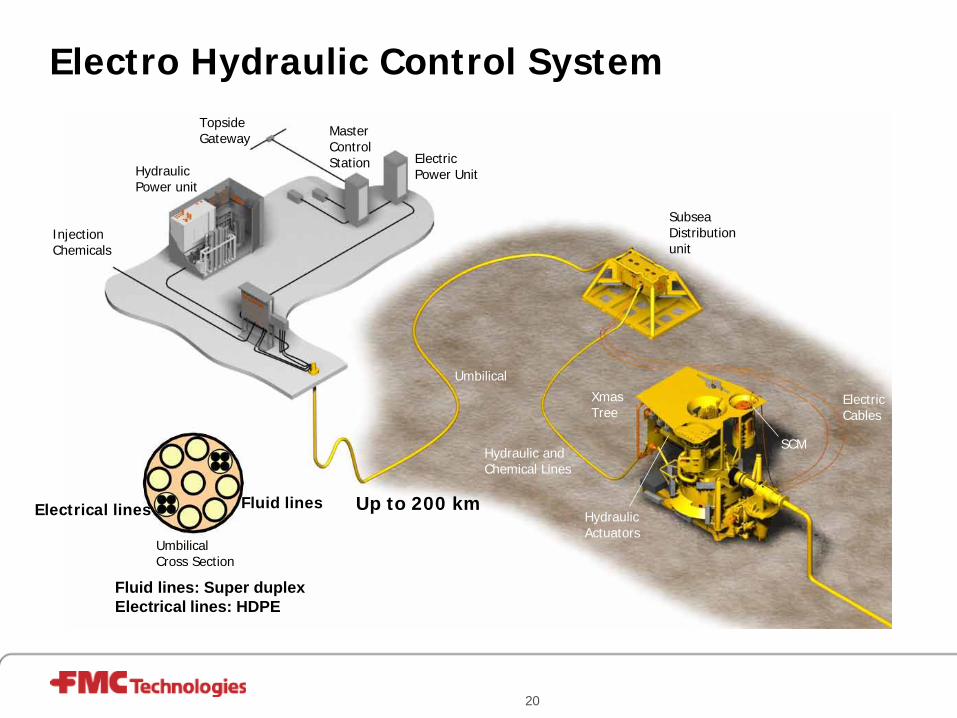
Electro Hydraulic Control System
HydraulicActuators
InjectionChemicals
HydraulicPower unit
XmasTree
SubseaDistributionunit
Umbilical Cross Section
ElectricCables
Umbilical
MasterControlStation Electric
Power Unit
TopsideGateway
Hydraulic and Chemical Lines
SCM
Up to 200 kmFluid linesElectrical lines
Fluid lines: Super duplexElectrical lines: HDPE

21
Subsea Control Umbilical - Typical
Topsides Termination Subsea Termination
§ Connects topsides control equipment to subsea field equipment
§ Routes hydraulic and electric power and chemicals to subsea field
§ Routes signals between topside and subsea equipment
Cross Section

22
Subsea Control Module (SCM)
Lifting Adapter
Anti-Rotation Guide Pin
Locking Mechanism
Hyd. Couplers
Elec. Connectors
Elec. Connectors
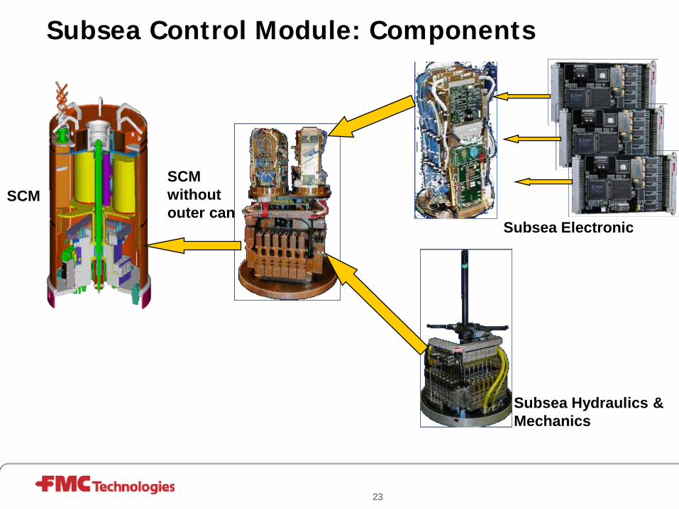
23
Subsea Electronic
Subsea Hydraulics &Mechanics
Subsea Control Module: Components
SCM withoutouter can
SCM

Typical operator display picture

DHSV
PMV PWV
Choke
Manifold HIPPSFlowline
Production Riser
Riser EV
Utility Riser
CIV
EUC 1
EUC 2
Isolation of well from environment (OLF 070)
Subsea Control Safety Requirement
• ESD of single well to SIL 3
• PSD of single well to SIL 1
• HIPPS to SIL 3
• Workover to SIL 2
Flow assurance
• Natural flow
– Pressure balancing using chokes
– Flow optimization in flow lines
– Well testing
• Flow boost
– Gas lift, in riser, in well
– Booster pumps
Flow assurance
• Hydrates
– “ice” created of gas, water and oil
– Stable in cold, deep water
– Methanol or MEG anti frost
• Wax, asphalt, corrosion
– Injection of wax, asphalt and corrosion inhibitor
• Pigging
– Scraping plug pumped through flowline

Conductor interface
Hydrate formation in 1200 m water depth

Subsea Instrumentation
Vega as example
Vega is a gas & codensate field in the North Sea
Sofisticated instrumentation due to high pressure and split of production between different owners
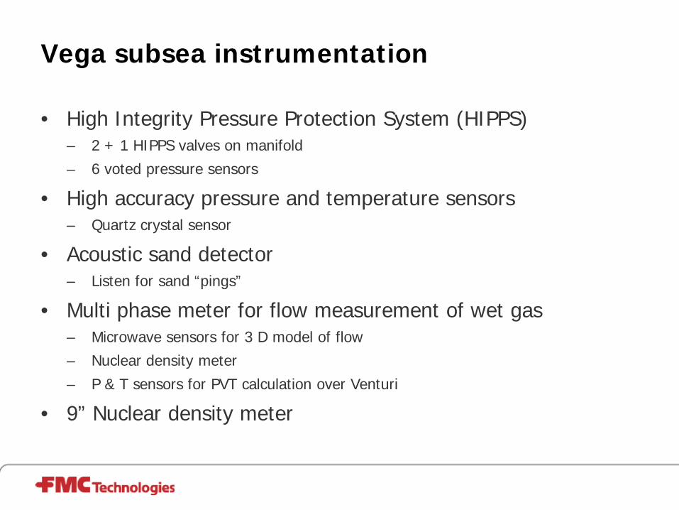
Vega subsea instrumentation
• High Integrity Pressure Protection System (HIPPS)– 2 + 1 HIPPS valves on manifold
– 6 voted pressure sensors
• High accuracy pressure and temperature sensors– Quartz crystal sensor
• Acoustic sand detector – Listen for sand “pings”
• Multi phase meter for flow measurement of wet gas– Microwave sensors for 3 D model of flow
– Nuclear density meter
– P & T sensors for PVT calculation over Venturi
• 9” Nuclear density meter

Vega field
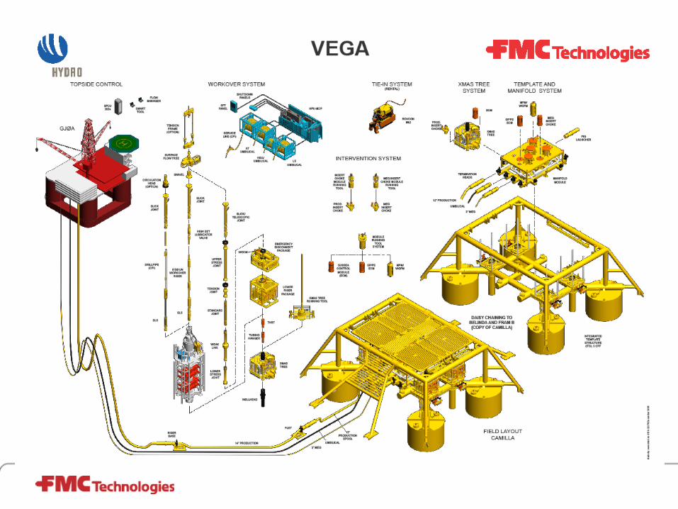

Vega template & manifold
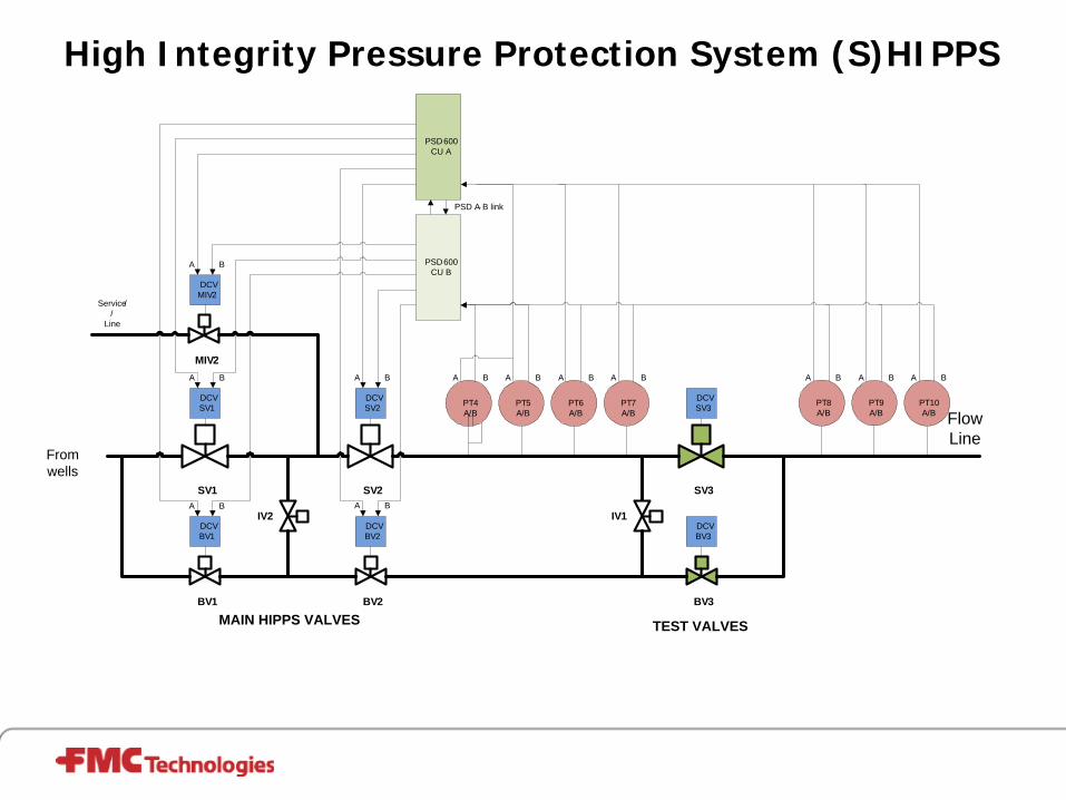
High Integrity Pressure Protection System (S)HIPPS
PSD600 CU A
PSD A- B link
SV1
SV2
SV3
Flow Line
BV1
BV2
BV3
MIV2
DCV BV1
DCV SV1
DCV MIV2
DCV SV2
DCV BV2
DCV SV3
DCV BV3
PT6A/B
PT7A/B
PT4A/B
PT5A/B
PT10A/B
PT8A/B
PT9A/B
PSD600 CU B
A B A B A B A BA B
A B
A B
A B
A B
Service//
Line
IV2 IV1
A B A B A B
From wells
MAIN HIPPS VALVES TEST VALVES

SIL 3 controller hardware architecture
PSD SYSTEM SIDE A PSD SYSTEM SIDE B
PSD600 Control Unit
Sensors Output to final elements
Top Side
Sub Sea
SC1
SC2
ETH
PSD600 Control Unit
SensorsOutput to final elements
SC1
SC2
ETH
Umbil
ical
PSD600 Control Unit
Switches Output
SC1
SC2
ETH
PSD600 Control Unit
SwitchesOutput
SC1
SC2
ETHCANFrom CAN
sensors
CAN CANFrom CAN Sensors
CAN
From CAN sensors
From CAN SensorsComm.
Power
Comm.
Power
Direct link
Direct link
Direct link
Direct link
SCUA
SCUB
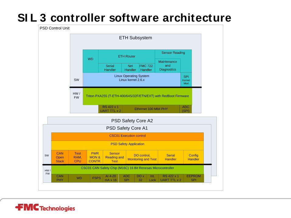
SIL 3 controller software architecture
PSD Safety Core A2
ETH Subsystem
PSD Safety Core A1CSC01 Execution control
PSD Safety Application
PSD Control Unit
Triton PXA255 (T-ETH-400/64S/32F/ETN/EXT) with RedBoot Firmware
Sensor Reading
Linux Operating SystemLinux kernel 2.6.x
FMC 722 Handler
Serial Handler
Net Handler
Maintenance and
Diagnostics
ETH Router
RS 422 x 1UART TTL x 2 Ethernet 100 Mbit PHY
SW
HW /FW
RS 422 x 1UART TTL x 2
DO x 32
AI 4-20 mA x 16
CAN PHY
CSC01 CAN Safety Chip (M16C) 16 Bit Renesas Microcontroller
CAN Open Stack
TestRAM, CPU
Serial Handler
DO control, Monitoring and Test
Sensor Reading and
Test
ADCSPI
EEPROMSPI
Config Handler
SW
HW /FW
ADC(SPI)
WD
SPIKernel Mod
WD Int. LockFSPS
PWR MON &
CONTR.

PT/TT FUNCTIONAL COMPONENTS
FLOW LINE
HARNESSADAPTER
PENETRATOR
ADC BOARD
CONTROLBOARD
ELECTRONICS
PROBE
TRANSDUCER

PT/TT FUNCTIONAL COMPONENTS
HOUSING MODULE:
• The module is consisting of an flange with a probe for process interface and cylindrical housing for the containment of the electronic boards.
• The electronics is contained in atmospheric pressure sealed with glass-metal penetrator towards the ambient pressure.
• The jumper connection is done via an adapter module.
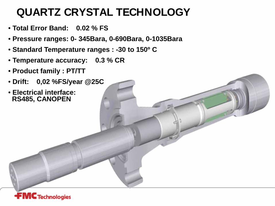
QUARTZ CRYSTAL TECHNOLOGY• Total Error Band: 0.02 % FS• Pressure ranges: 0- 345Bara, 0-690Bara, 0-1035Bara• Standard Temperature ranges : -30 to 150º C• Temperature accuracy: 0.3 % CR• Product family : PT/TT• Drift: 0,02 %FS/year @25C• Electrical interface: RS485, CANOPEN

Sand detector Working principle
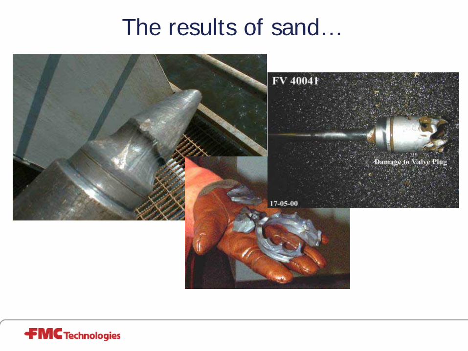
The results of sand…

ClampOn DSP Particle Monitor Subsea
DEEPWATERØ Weight 18 kgØ 4500 Meter Water DepthØ Intelligent DSP Processing = improved S/N ratioØ ROV installable sensor
COMPACT SUBSEAØ Weight 8 kgØ 3000 Meter Water DepthØ Intelligent processing = improved S/N ratioØ ROV installable sensor & clamp
ALL SYSTEMS•Fast economical installation•No drilling, welding or pressure drop•Digital communication between field and computer

ClampOn’s Subsea Philosophy!
Titanium body
Jumper interface
High pressure chamber with silicon oil
Glass-metal penetrator
Atmospheric chamber
Electronic beam weldings
No o-rings, gaskets or mechanical seals!

Subsea multiphase meters on each well
Allows for accurate and continuous online well allocation
– Multi-rate testing to be performed whenever desired
Reduced need for well testing by using topside test separator; only needed for verification:
– Represents redundant solution
– Yearly or when indication of anomalies
– Reduces host platform ”deferred production”
Results in substantial well regularity improvement
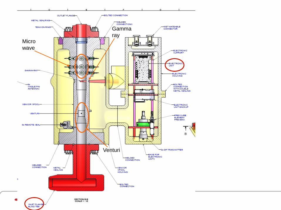
Micro wave
Gamma ray
Venturi

Subsea seabed separation
• Separate water and sand from oil – Produced fluid may contain 90 % water from old wells
– Remove and re-inject water and sand close to well
– Avoid transport of water long distance for separation on surface
• Separate heavy oil from gas on deep fields– Pump heavy oil to surface, natural well pressure will not lift oil
– Gas to surface by natural flow

Subsea Separation
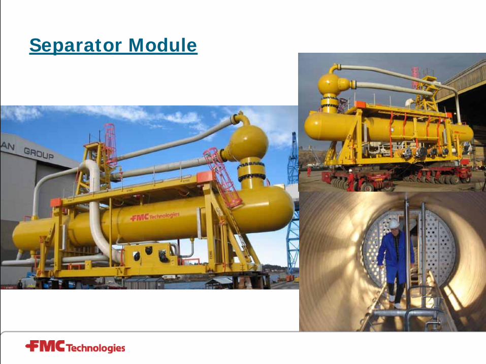
Separator Module
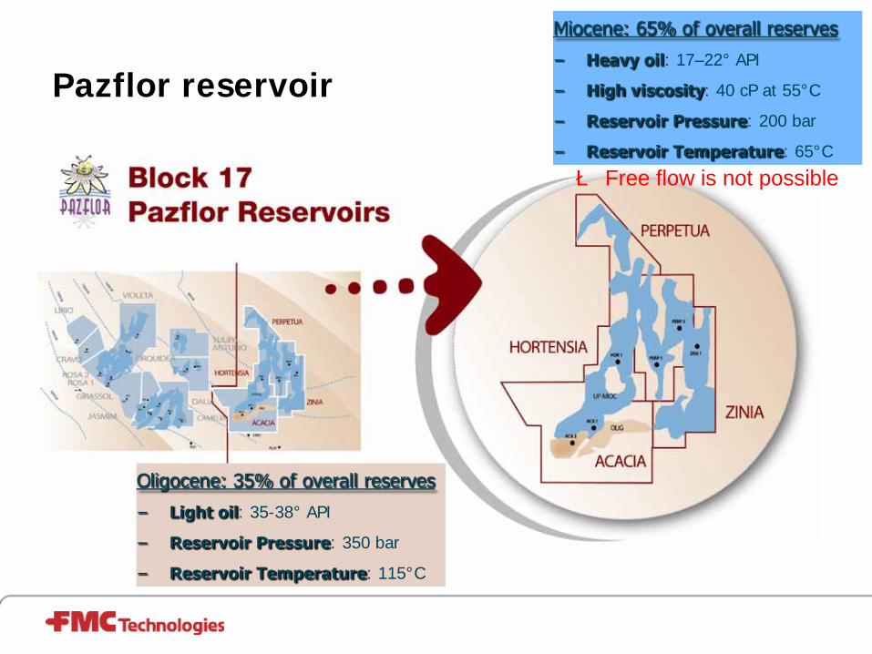
Pazflor reservoir
Miocene: 65% of overall reserves
− Heavy oil: 17–22° API
− High viscosity: 40 cP at 55°C
− Reservoir Pressure: 200 bar
− Reservoir Temperature: 65°C
Oligocene: 35% of overall reserves
− Light oil: 35-38° API
− Reservoir Pressure: 350 bar
− Reservoir Temperature: 115°C
è Free flow is not possible

Solution - Subsea Processing
• Gas / Liquid Separation and Liquid Boosting:– Gas flows freely to the FPSO
• Hydrate preventions of flow lines by means of depressurization is possible
• Reduced cost due to elimination of circular flow line
– Liquid out of separator with relative low gas fracttion
• Efficient pumps with high ∆P can be used → Increased recovery & less power
consumption
– Boosting of liquid• Stabilized flow regime in risers reduces
slugging

LC
Pumps
Sep gasXV
SepinletXV
Separatorliquid XV
Sepinlet
bypassXV
Risertop XV
Pumpoutlet XV
Chokevalve
PMV
PWV
Risertop XV
ROV
LAH
RO
PC
23bar 60°C
LAL
SSU Process Principle
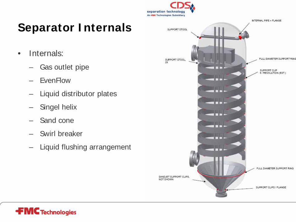
Separator Internals
• Internals:
– Gas outlet pipe
– EvenFlow
– Liquid distributor plates
– Singel helix
– Sand cone
– Swirl breaker
– Liquid flushing arrangement

Level Measurement
• Subsea Nucleonic Density Profiler:
– Nucleonic source array (Cesium 137-50mCi)
– Two detector arrays with Geiger Müller tubes
– Topside PLC
• Source and detectors installed in dip pipes
• Detectors are retrievable, whereas nucleonic source is permanently installed
• Primary function is to measure liquid level, but provides also information about density distribution between HH and LL

Test Overview
• EFAT of:– Control System
– Pump Systems
• Interchangeability of modules
• System Integration Test of all SSU
• Shallow Water Test of SSU#2
• Function Test of SSU#1

Snøhvit
Ormen Lange
Longest & deepest fields
Tormore-Laggan
Shell Perdido
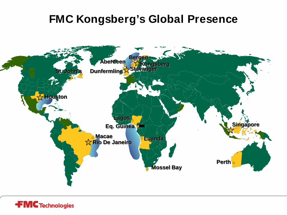
FMC Kongsberg’s Global Presence
Houston
Kongsberg
Singapore
Dunfermline
Rio De Janeiro
St. John’s
Macae
LagosEq. Guinea
Luanda
AberdeenBergen
Stavanger
PerthMossel Bay
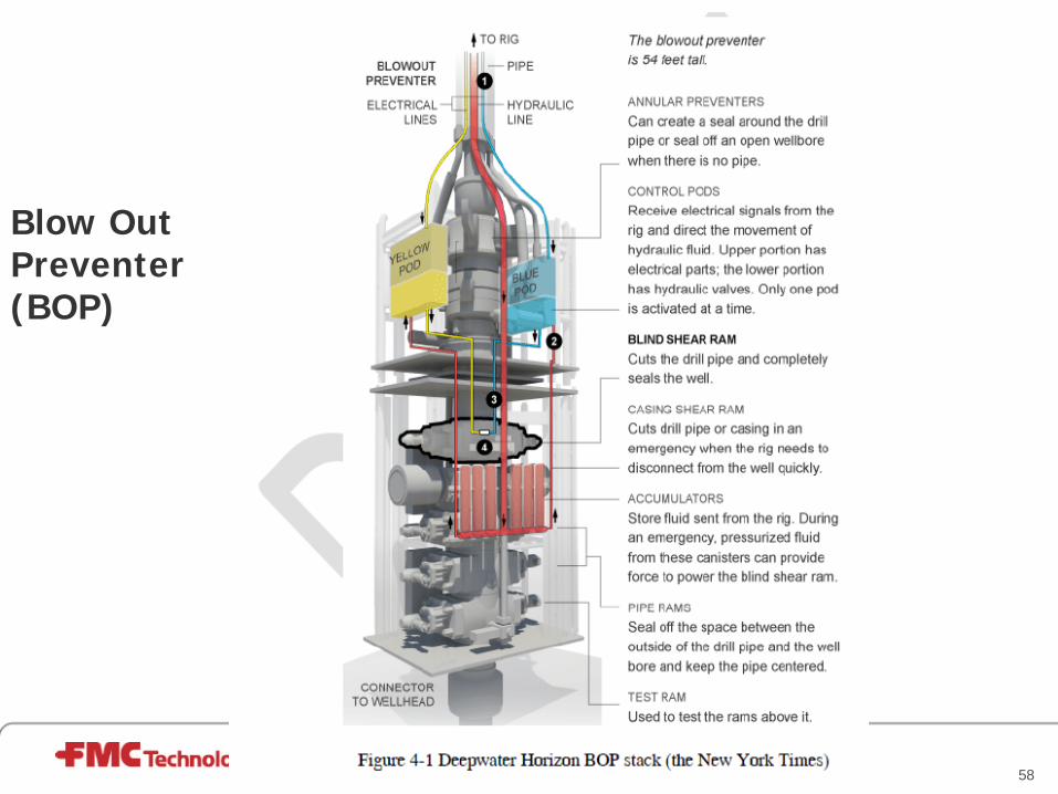
Blow Out Preventer (BOP)
58

BP Macondo Shear ram failure
59

BOP shear RAM
60
Thank You for Your Attention!