nt® high-temperature electronic flowmeter, model 4401 …
TRANSCRIPT

NT® HIGH-TEMPERATURE ELECTRONIC FLOWMETER, MODEL 4401
User Guide
P/N 1400 (Rev. A 08/12)

ENTEGRIs, INC. Customer Service Tel. +1 952 556 4181 Customer Service Fax +1 952 556 8022 1
NT HIGH-TEMPERATURE ELECTRONIC FLOWMETER, MODEL 4401
Table of ContentsIntroduction ............................. 2
Dimensions ........................... 3
Installation .......................... 5
Provided Equipment ................ 5
Operating Environment ............ 5
Mounting Requirements ........... 5
Bleed Ports ............................ 6
Mechanical Installation ........... 6
Electrical Installation ............. 7
Power Supply Requirements ...... 7
Circuit Protection ................... 7
Input Power ........................... 7
Output Signals ........................ 7
Electrical Connections ............. 8
Wiring Diagram ...................... 9
Load Resistance ..................... 10
Unit Operation ..................... 10
Sensor Module ....................... 10
Operating Pressure Requirements ........................ 10
Flow Accuracy ....................... 11
Pressure Accuracy .................. 11
Pressure Drop Charts .............. 11
Determining the Flowmeter CV ........................ 12
Diagnostics .......................... 12
Maintenance ........................ 15
Normal Operation .................. 15
Flowmeter Re-zero Function .... 15
Flushing Impulse Tubes and Internal Areas ....................... 16
Reference ............................ 17
Physical Specifications ............ 17
Electrical Specifications .......... 17
Performance Specifications ...... 18
Ordering Information ............. 19
Certifications ....................... 20
CE Certification ..................... 20
UL Certification ..................... 20
Repair and Warranty Service ... 21
Technical Support ................. 21
For More Information ............ 21
Terms and Conditions ............ 21
Product Warranties ............... 21

2 Customer Service Tel. +1 952 556 4181 Customer Service Fax +1 952 556 8022 ENTEGRIs, INC.
NT HIGH-TEMPERATURE ELECTRONIC FLOWMETER, MODEL 4401
IntroductionThis user guide is for use with the NT® high-temperature electronic flowmeter, model 4401.
The flowmeter is designed for use in high-temperature, high-purity applications, primarily in the semi-conductor industry and is compatible with highly corrosive processes.
The instrument measures flow rate without using moving parts or fill fluids, reducing the possibility of a contaminated process.
The flowmeter utilizes a remote orifice module which the high tem-perature media passes through.
This maintains cooler and relative constant temperatures in the flowmeter sensor module.
The flowmeter calculates fluid flow from the differential pressure measured by two sensors separated by a venturi style integral orifice. The unit provides two electrical output signals, each 4 – 20 mA, one for flow rate and another for pres-sure measurement. The pressure measurement is taken from the outlet of the flowmeter.
Top View
Bleed ports
Upstream bleed port
Inlet pressure
Downstream bleed port
Outlet pressure
Inlet pressure
Outlet pressure
Impulse tubes
Sensor module
Orifice module
Inlet portconnection
(hot fluid in)
Outlet portconnection(hot fluid out)

ENTEGRIs, INC. Customer Service Tel. +1 952 556 4181 Customer Service Fax +1 952 556 8022 3
NT HIGH-TEMPERATURE ELECTRONIC FLOWMETER, MODEL 4401
DimensionsFlareLock® II
2 × A
19.6 mm (0.77”)
82.0 mm(3.23”)
23.9 mm (0.94”)
16.0 mm(0.63”)
127.0 mm(5.0”)
114.0 mm(4.49”)
53.3 mm (2.10”)
40.1 mm (1.58”)
Outlet port connection
Inlet port connection
B
152.4 mm (6.00”) standard 304.8 mm (12.00”) optional 914.4 mm (36.00”) optional
50.8 mm(2.00”)
Top View
Side View
Inlet/Outlet Port Connection
Dimensions
A B
R02 22.9 mm (0.90”) 151.9 mm (5.98”)
R03 22.9 mm (0.90”) 158.0 mm (6.22”)
R04 30.5 mm (1.20”) 162.0 mm (6.38”)
R06 38.6 mm (1.52”) 165.6 mm (6.52”)
R08 48.3 mm (1.90”) 180.3 mm (7.10”)

4 Customer Service Tel. +1 952 556 4181 Customer Service Fax +1 952 556 8022 ENTEGRIs, INC.
NT HIGH-TEMPERATURE ELECTRONIC FLOWMETER, MODEL 4401
Super 300 Type Pillar® Fitting
2 × A
19.6 mm (0.77”)
82.0 mm(3.23”)
9.7 mm (0.38”)
127.0 mm(5.0”)
114.0 mm(4.49”)
50.8 mm(2.00”)
53.3 mm (2.10”)
40.1 mm (1.58”)
Outlet port connection
Inlet port connection
B
152.4 mm (6.00”) standard304.8 mm (12.00”) optional914.4 mm (36.00”) optional
Top View
Side View
Inlet/Outlet Port Connection
Dimensions
A B
W02 22.9 mm (0.90”) 140.0 mm (5.51”)
W03 22.9 mm (0.90”) 153.0 mm (6.02”)
W04 30.5 mm (1.20”) 157.0 mm (6.18”)
W06 41.6 mm (1.64”) 171.0 mm (6.73”)
W08 59.4 mm (2.34”) 187.6 mm (7.39")

ENTEGRIs, INC. Customer Service Tel. +1 952 556 4181 Customer Service Fax +1 952 556 8022 5
NT HIGH-TEMPERATURE ELECTRONIC FLOWMETER, MODEL 4401
Installation
Provided EquipmentThe product ships complete with the orifice module, sensor module and associated impulse tubes and fitting components. For units with FlareLock II connections, two nuts are included. For units with PrimeLock® connections, two nuts and two inserts are included. For units with Pillar connections, two nuts, two sleeves and two gauge rings are included.
NOTE: This unit has been assembled and double-bagged under cleanroom conditions. To maintain purity, only open in cleanroom environment.
! CAUTION: Do not tighten the nuts that protect the tube connections during shipment unless the proper tubing has been installed. Tight-ening these nuts may result in damage to the PFA and PTFE flowmeter tube connections.
Operating EnvironmentThe flowmeter sensor module is to be mounted in an indoor, climate controlled environment. Refer to Reference section on page 17 for specifications.
Mounting RequirementsThe flowmeter may be mounted in any orientation. The orifice module can be oriented vertically or horizon-tally or any angle in between. The orifice module can be above or below the sensor module. However, during normal operation, orienting the flow-meter with the orifice module higher in elevation than the sensor module may allow for any possible bubble accumulation in the impulse tubes to rise up and be dispersed into the main media flow stream (see Figure 1).
The flowmeter does not require straight lengths of tubing at the inlet or the outlet port connection.
For best performance, mount the flowmeter orifice module at relative elevation lower than the point of dispense and maintain positive of at least 6.9 kPa (1 psig) of internal pressure on the sensors at all times.
Figure 1. Mounting options

6 Customer Service Tel. +1 952 556 4181 Customer Service Fax +1 952 556 8022 ENTEGRIs, INC.
NT HIGH-TEMPERATURE ELECTRONIC FLOWMETER, MODEL 4401
The flow direction of both the orifice module and the sensor module must match (see Figure 2). If disassembly is required, ensure that the unit is reassembled properly, matching the serial numbers of the orifice module to sensor module.
NOTE: When connecting the flow-meter to the process tubing, verify the direction of flow corresponds to the inlet and outlet port connections of the flowmeter orifice module (the process fluid must enter at the inlet and exit at the outlet). A flowmeter installed backwards will output an erroneous flow and pressure signal (see Figure 2).
Bleed PortsBleed ports are provided on the sensor module to remove air bubbles or flush liquids from the impulse tubes and sensor module internal areas.
Tubing can be installed permanently with with manual valves or other types of valves for repeated bleed-ing, if needed. Tubing may also be temporarily attached for bleeding and then removed and the connec-tions capped.
Mechanical InstallationDo not subject the flowmeter sensor module to high heat during installa-tion. The sensor module base bracket must be mounted to a solid surface to ensure stability. Verify all fitting connections and the signal cable are free from mechanical stress from the surrounding equipment. Use #10 or M4 pan head screws with flat washers for mounting (see Figure 3).
Care should be taken when install-ing the flowmeter to avoid leaks. Do not use excessive torque when tightening the tubing connections. The flowmeter must be used with the proper tubing size and fittings.
Install a two-way valve downstream from the flowmeter. The valve is required to perform the flowmeter re-zero function. Please refer to Maintenance section on pages 15–16 for more information concerning the re-zero function.
Figure 2. Flow direction
Figure 3. Recommended hardware
#10 (M4)Pan head
#10 (M4)Flat washer

ENTEGRIs, INC. Customer Service Tel. +1 952 556 4181 Customer Service Fax +1 952 556 8022 7
NT HIGH-TEMPERATURE ELECTRONIC FLOWMETER, MODEL 4401
Electrical Installation
Power Supply RequirementsThe power supply for the flowmeter must provide clean power and must be used only to power similar mea-
surement-type devices. The power supply must not be used to power inductive loads, such as motors, relays or solenoids. These devices may produce transients that may affect the flowmeter measurements when such an inductive device is powered up or powered down.
In addition to providing clean power, the instrumentation signals and power return lines must not be run within the same conduit or cable. Heavy current demands from motors, charging capacitors or other induc-tive loads may cause a voltage change within the instrumentation signal line, causing erroneous output readings from the flowmeter.
Circuit ProtectionUse a 1 Amp rated, time lag fuse. A single fuse can be used for all three input power lines combined, or indi-vidually, as preferred.
Input PowerThe flowmeter requires a nominal 24 VDC (12–28 VDC input voltage) to operate. The Electrical Specifications section on page 17 describes the unit input power requirements.
Output SignalsThe flowmeter provides two optically isolated analog 4 – 20 mA output signals, one signal for flow and one signal for pressure. Each analog output signal uses a standard two-wire system that requires a 24 VDC (12–28 VDC) power supply with less than 2% ripple at 100 or 120 hertz. The required power supply voltage (VPS) for the output signal(s) varies with the maximum load resistance, RLoad (see Figure 9 on page 10). Flowmeter output signals are described in Figures 11 and 12 on page 11. Input and output signals to the flowmeter are supplied through an 8-wire FEP-jacketed pigtail cable or 8-wire removable PVC-jacketed electrical connector (D-Series connector), located on the cover of the flowmeter.
Sensor module
2-way valve (required for
re-zero function)
Orifice module
Inlet port connection
Outlet port connection
Figure 4. Flowmeter with 2-way valve

8 Customer Service Tel. +1 952 556 4181 Customer Service Fax +1 952 556 8022 ENTEGRIs, INC.
NT HIGH-TEMPERATURE ELECTRONIC FLOWMETER, MODEL 4401
Electrical ConnectionsRefer to Figure 6 on page 8 for the
pigtail and 8-pin connector wiring diagram.
8-wire Pigtail
D-series Connector Function
Black Pin 1/Black Ground (+24 VDC common)
Red Pin 2/Red +24 VDC
Brown Pin 3/Brown Pressure output, 4 – 20 mA output
Yellow Pin 4/Yellow Pressure output, +24 VDC supply
Orange Pin 5/Orange Flow output, +24 VDC supply
Blue Pin 6/Blue Flow output, 4 – 20 mA output
Violet Pin 7/Violet Re-zero input
White Pin 8/White Factory use only – do not connect
Shield Shield Earth ground or chassis ground
Figure 6. Wiring diagram
Figure 5. 8-wire connector (D series connector)
1
2
34
5
6
78
A
A+-
+-
Red
Black
Orange
Blue
Yellow
Brown
Power loop
+24 VDC Supply (VPS)
-
+24 VDC Supply (VPS)
-
+24 VDC Supply (VPS)
-
Vm=IxRm RLoad(optional)
Vm=IxRm RLoad(optional)
Flow outputloop
Pressure outputloop RLoad = Optional load resistor (ohms)
Vm = Maximum voltage drop across meter at 20 mA
Rm = Internal resistance of meter (ohms)

ENTEGRIs, INC. Customer Service Tel. +1 952 556 4181 Customer Service Fax +1 952 556 8022 9
NT HIGH-TEMPERATURE ELECTRONIC FLOWMETER, MODEL 4401
03-Brown
06-Blue
07-Violet
Factory use only08-White
Electrical cable
01-Black (-)
02-Red (+)
Normally open switch
i
INFORMATION NOTICE
+
-
+
-
+
-
+
-
05-OrangeFlow loop
04-YellowPressure loop
For re-zeroing(recommended)
Power supply24 VDC ±10%
Power supply24 VDC ±10%
Flow display or other monitoring device
Pressure display or other monitoring device
The unit requires instrumentgrade “regulated” power forproper functioning.
Electrical cable
Figure 7. Power and re-zero wiring
Figure 8. flow and pressure signal wires
Wiring Diagram

10 Customer Service Tel. +1 952 556 4181 Customer Service Fax +1 952 556 8022 ENTEGRIs, INC.
NT HIGH-TEMPERATURE ELECTRONIC FLOWMETER, MODEL 4401
Load ResistanceIf a load resistor, RLoad, is used in series with the current output (flow and pressure outputs), the value of RLoad is dependent on the supply voltage and the meter resistance and is calculated from the following formula:
where:
RLoad = maximum load resistance
VPS = power supply voltage
Rmeter = meter resistance (theoretically = 0)
If RLoad is calculated using a voltage drop across the meter (Vm), the following equation is used:
Figure 9 shows the power required for a 4–20 mA loop.
Unit Operation
Sensor ModuleThe sensor module is factory sealed and should not be tampered with.
NOTE: Any attempt to remove or tamper with the sensor module or any other parts of the unit will void the warranty.
Operating Pressure RequirementsThe flowmeter calculates fluid flow from the difference in pressure (measured by two sensors) across a venturi style orifice. For the flowme-ter to perform within specification, a minimum of 7 kPa (1.0 psig) must be present at the outlet of the orifice module. Maximum pressure is 414 kPa (60 psig).
Follow fitting design maximum pres-sure capability for the maximum temperature of your fluid media.
! CAUTION: The flowmeter may be damaged if it is subjected to any level of vacuum pressure (less than atmospheric pressure).
RLoad = VPs - 12
- Rmeter 0.02
RLoad = 50 * (VPs - 12 - Vm)
800
600
0
12Power Supply Voltage
(VPS)
R Loa
d (O
hms)
24 28
Operating region
Figure 9. Power required for a 4 – 20 mA loop.
ENTEGRIs, INC. Customer Service Tel. +1 952 556 4181 Customer Service Fax +1 952 556 8022 11
NT HIGH-TEMPERATURE ELECTRONIC FLOWMETER, MODEL 4401
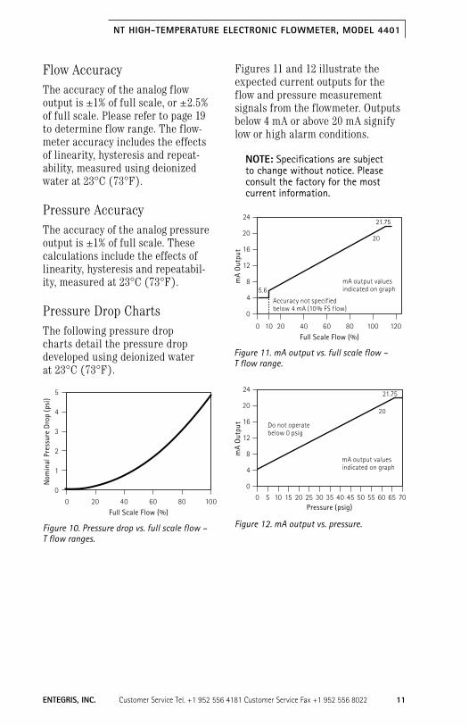
Flow AccuracyThe accuracy of the analog flow output is ±1% of full scale, or ±2.5% of full scale. Please refer to page 19 to determine flow range. The flow-meter accuracy includes the effects of linearity, hysteresis and repeat-ability, measured using deionized water at 23°C (73°F).
Pressure AccuracyThe accuracy of the analog pressure output is ±1% of full scale. These calculations include the effects of linearity, hysteresis and repeatabil-ity, measured at 23°C (73°F).
Pressure Drop ChartsThe following pressure drop charts detail the pressure drop developed using deionized water at 23°C (73°F).
Figures 11 and 12 illustrate the expected current outputs for the flow and pressure measurement signals from the flowmeter. Outputs below 4 mA or above 20 mA signify low or high alarm conditions.
NOTE: Specifications are subject to change without notice. Please consult the factory for the most current information.
Figure 10. Pressure drop vs. full scale flow – T flow ranges.
20
Nom
inal
Pre
ssur
e D
rop
(psi
)
Full Scale Flow (%)60 800 40 100
5
4
3
2
1
0
Figure 11. mA output vs. full scale flow – T flow range.
2010
mA
Out
put
Full Scale Flow (%)60 800 40 100 120
24
20
16
12
8
4
0
20
21.75
5.6
Accuracy not specifiedbelow 4 mA (10% FS flow)
mA output valuesindicated on graph
Figure 12. mA output vs. pressure.
mA
Out
put
Pressure (psig)0 5 10 15 20 25 30 35 40 45 50 55 60 65 70
24
20
16
12
8
4
0
20
21.75
Do not operate below 0 psig
mA output valuesindicated on graph

12 Customer Service Tel. +1 952 556 4181 Customer Service Fax +1 952 556 8022 ENTEGRIs, INC.
NT HIGH-TEMPERATURE ELECTRONIC FLOWMETER, MODEL 4401
Determining the Flowmeter CV The CV of the flowmeter using deion-ized water at 23°C (73°F) is listed in Table 1. CV coefficient is the number of gallons of water that will pass through the orifice in one minute at a pressure drop of 7 kPa (1.0 psig).
Diagnostics Troubleshooting the flowmeter may be accomplished by measuring the current (4 – 20 mA) output signal of the flowmeter with a battery powered current/voltage meter. The meter may be placed in series with a flowmeter output to measure the current output or it may be used to directly measure the voltage from a load resistor. Using the battery powered current/volt meter is an effective method to determine whether the Entegris device or the on-site data acquisition system is not functioning properly.
TABLE 1. Cv COEFFICIENTs OF FLOW RANGEs
Flow Range CV
T0 0.006
T1 0.015
T2 0.031
T3 0.061
T4 0.15
T5 0.31
T6 0.61
T7 1.2
T8 2.4
T9 4.9
T10 7.3
T11 11.0
T12 14.6

ENTEGRIs, INC. Customer Service Tel. +1 952 556 4181 Customer Service Fax +1 952 556 8022 13
NT HIGH-TEMPERATURE ELECTRONIC FLOWMETER, MODEL 4401
Diagnostic Guide*
symptom Possible Causes suggestions
1. Current output reads 4 mA or less when fluid flow is present.
The flowmeter is installed backwards.
Install the flowmeter so the direction of flow is from inlet port connection towards outlet port connection.
The flowmeter was accidentally re-zeroed while flow was present.
Make sure the flow is stopped and that there is a minimum of 7 kPa (1 psig) static line pressure present; then re-zero the flowmeter. See Re-zero Function, page 15.
Insufficient back pressure.
If the back pressure is being created by a column of liquid, the column height must be greater than 28 inches of water 7 kPa (1 psig). Some liquid may require greater height due to lower density.
The actual flow is lower than the specified flow range for the flowmeter.
A flowmeter configured to a different flow range is required. For example, if the flow-meter is a T7 0 –101 L/min. unit, any flow less than 1.0 L/min. will read 4 mA. Please contact Entegris for additional product information.
Impulse tubes are crossed.
Reinstall impulse tubes with proper orientation.
Bubbles in impulse tube(s).
Purge the bubbles.
2. Output reads above 4 mA when there is zero flow.
The flowmeter needs to be re-zeroed.
Perform the re-zeroing procedure. Make sure the flow is stopped and a minimum of 7 kPa (1 psig) static line pres-sure is present; then re-zero the flowmeter.
Verify the re-zero pressure using the flowmeter’s pressure output.
See Re-zero Function, page 15.
3. Current output does not vary with changes in flow.
The pressure output is being monitored instead of the flow output.
Check the wiring to ensure the flow output is wired correctly.
Insufficient back pressure.
If the back pressure is being created by a column of liquid, the column height must be greater than 28 inches of water 7 kPa (1 psig). Some liquid may require greater height due to lower density.
* Please contact Entegris for further diagnostic assistance.

14 Customer Service Tel. +1 952 556 4181 Customer Service Fax +1 952 556 8022 ENTEGRIs, INC.
NT HIGH-TEMPERATURE ELECTRONIC FLOWMETER, MODEL 4401
Diagnostic Guide (continued)
symptom Possible Causes suggestions
Impulse tubes are crossed.
Reinstall impulse tubes with proper orientation.
Bubbles in impulse tube(s).
Purge the bubbles.
The 4–20 mA loop signal is shorted to the power (+24 V) of the flowmeter.
Examine all electrical connections. Note that. if wires are stripped back too far before insertion in a terminal block, they may cross and short together.
4. Current output is extremely high (>25 mA).
The actual fluid flow or pressure conditions are excessive.
Lower the flow rate or applied fluid pressure
Select higher range flowmeter.
5. Output is extremely noisy (spiking above and below 20 and 4 mA)
The supply power (+24 V) is noisy.
If the power supply is shared with other systems, components such as solenoids, DC motors, valves, etc., the flowmeter may be receiving “dirty” power. The noise spikes on the power supply will cause the flowmeter output to be noisy. See page 7 (Electrical Installation).
The actual fluid flow or pressure conditions are noisy.
Flow turbulence may be caused by “noisy” pumps used in a system. Examples of noisy pumps are diaphragm pumps without pulsation dampeners and peristaltic pumps operating at low flow rates.
6. Flow inaccuracy at low operating flow rates.
The flowmeter needs to be re-zeroed.
Perform the re-zeroing procedure. Make sure the flow is stopped, and a minimum of 7 kPa (1.0 psig) static line pressure is present, then re-zero the flowmeter.
Verify the re-zero pressure using the flowmeter’s pressure output.
See Re-zero Function, page 15.
Insufficient back pressure (< 7 kPa (1.0 psig).
Check pressure output value. If below 4.26 mA (1.0 psig) at all operational flow rates (including zero flow), move flowmeter or increase back pressure.
Heat loss due to low flow.
Increase flow. With low flow, heat can escape the chemical media affecting of the viscosity of the media. The unstable viscosity will diminish the flow measurement.

ENTEGRIs, INC. Customer Service Tel. +1 952 556 4181 Customer Service Fax +1 952 556 8022 15
NT HIGH-TEMPERATURE ELECTRONIC FLOWMETER, MODEL 4401
Maintenance
Normal Operation During normal operation, the flow-meter requires little maintenance, other than a periodic re-zero of the flowmeter and possible periodic flushing of bubbles in the impulse tubes between the flowmeter orifice module and the sensor module.
Flowmeter Re-zero Function The calibration of the flowmeter can be re-zeroed, meaning that the analog output that corresponds to zero flow may be reset.
WARNING! When executing the re-zero function, there must be 7– 414 kPa (1– 60 psig) of static pressure. Best results when re-zero is performed at the operating pressure.
NOTE: The following procedure must be followed precisely to ensure proper flowmeter re-zero.
1. The flowmeter re-zero function requires the same power supply of 24 VDC (±12 – 28 VDC) as is used to power the unit.
2. Stop the process fluid flow and verify that the flowmeter is experiencing absolutely no flow (typically requires a fully closed process valve in the fluid stream located on the outlet side of the orifice module).
3. Using the pressure output signal of the flowmeter, verify that there is at least 7 kPa (1.0 psig) [414 kPa (60 psig)] maximum of stable static line pressure.
4. Apply 24 VDC (12 – 28 VDC) to the violet wire for a minimum of three seconds. This voltage supply must use the same ground as the power supply for the flowmeter.
5. Release the 24 VDC (12 – 28 VDC) from the violet wire. Re-zero sequence is now complete.
!
Diagnostic Guide (continued)
symptom Possible Causes suggestions
7. Flow inaccuracy such as hysteresis, linearity, repeat-ability and no output.
Damage by heat. Sensor module can be damaged by excessive heat from the impulse tube during setup or purging air bubbles. Do not purge bubbles with heat or allow the sensors to be heated by the media. See page 15 (Maintenance) for details.
Sensor module serial number does not match orifice module serial number.
Match sensor module to orifice module.
Bubbles in impulse tube(s).
Purge the bubbles.

16 Customer Service Tel. +1 952 556 4181 Customer Service Fax +1 952 556 8022 ENTEGRIs, INC.
NT HIGH-TEMPERATURE ELECTRONIC FLOWMETER, MODEL 4401
In most applications, the re-zero procedure may be automated using switches, a PLC or other logic con-troller devices. In order to obtain best performance, the re-zero function should be performed, if possible, every day of service when operating at ambient temperature conditions. The re-zero function should be performed more often if operating at higher temperature. It is also recommended to perform a re-zero after start-up and after fluid temperature changes of greater than 5°C (9°F). Best performance will be achieved by re-zeroing between each dispense cycle.
Flushing Impulse Tubes and Internal AreasThe impulse tubes and sensor module internal areas can be fully flushed of all liquids or purged of all air bubbles.
1. Allow fluid media to fill the tubing of your system.
2. Open the upstream bleed port line valve to purge all air bubbles or flush existing liquid. Limit time to 25 seconds maximum with media exceeding 40°C. Close the bleed port line valve.
3. Open the downstream bleed port line valve to drain all air bubbles or flush existing liquid. Limit time to 25 seconds maximum with media exceeding 40°C. Close the bleed port line valve.
4. Monitor any air bubble accumula-tion in the impulse tubes and repeat purge as necessary.
5. Do not run for extended periods of time with bleed ports open. Short bleed durations keep the flow meter sensor module tem-perature as close to ambient as possible.
6. Bleed ports must be closed to properly measure flow during system operation.

ENTEGRIs, INC. Customer Service Tel. +1 952 556 4181 Customer Service Fax +1 952 556 8022 17
NT HIGH-TEMPERATURE ELECTRONIC FLOWMETER, MODEL 4401
Reference
* If CTFE is chosen for chemical capability, the sensor module temperature must be maintained below 40°C during purging.
Electrical Specifications
Electrical input: 24 VDC (12–28 VDC)
Electrical current (signal): 50 mA device current (+20 mA +20 mA for each analog output)
Signal output range: 4–20 mA (externally powered with 24 VDC; output varies proportionately with flow or pressure measured)
Maximum load resistance: 0 Ω @ 12 VDC
800 Ω @ 28 VDC
Maximum output current: 22 mA for flow signal, 22 mA for pressure signal
Electrical enclosure: NEMA 5/IP54
Physical Specifications
Materials of construction:
Wetted parts
Sensor module body PTFE
Orifice module body PFA
Sensor interface PFA or CTFE (CTFE is temperature limited)*
Impulse tubes PFA
Primary seal Kalrez® 6375 UP
Nonwetted parts
Polypropylene, polyethylene, PVDF and PVC or FEP-jacketed cable (in addition to materials listed above)
Inlet/outlet connection:
FlareLock II tube fitting, PrimeLock tube fitting, Super 300 Type Pillar tube fitting
Bleed port connection:
Flaretek® tube fitting, PrimeLock tube fitting, Super 300 Type Pillar tube fitting – 1⁄4”
Impulse tube connection:
FlareLock II tube fitting, PrimeLock tube fitting, Super 300 Type Pillar tube fitting – 1⁄4”

18 Customer Service Tel. +1 952 556 4181 Customer Service Fax +1 952 556 8022 ENTEGRIs, INC.
NT HIGH-TEMPERATURE ELECTRONIC FLOWMETER, MODEL 4401
Performance Specifications
Process temperature: 10°C – 180°C (20°F– 356°F) with PFA interface*
Storage temperature: 10°C – 65°C (20°F – 149°F)*
Operating pressure: 0 – 414 kPa (0 – 60 psig)
Minimum outlet pressure: 7 kPa (1.0 psig)
Non operating maximum pressure:
0 – 690 kPa (0 – 100 psig)**
Response time: 50 msec update rate
Flow measurement accuracy:
20 –100% of range ±1.0% of full scale
10 –20% of range ±2.5% of full scale
Accuracy stated as % of full scale using deionized water at 23°C (70°F) and includes the combined effects of linearity hysteresis and repeatability
Flow measurement repeatability:
20 –100% of range ±0.5% of full scale
10–20% of range ±1.0% of full scale
Pressure output range: 0–414 kPa (0 – 60 psig)*
Pressure measurement accuracy:
±1.0% of full scale, includes the combined effects of linearity, hysteresis and repeatability
Pressure measurement repeatability:
±1.0% of full scale
* Contact Entegris for specific application support and expanded capabilities. ** Follow fitting design maximum pressure capability for the maximum
temperature of your fluid media.

ENTEGRIs, INC. Customer Service Tel. +1 952 556 4181 Customer Service Fax +1 952 556 8022 19
NT HIGH-TEMPERATURE ELECTRONIC FLOWMETER, MODEL 4401
Ordering Information The model number can be established using the following chart.
NT High-temperature Electronic Flowmeter
4401 High-temperature electronic flowmeter
Flow Range
T0 0–50 mL/min
T1 0–125 mL/min
T2 0–250 mL/min
T3 0–500 mL/min
T4 0–1250 mL/min
T5 0–2.5 L/min
T6 0–5 L/min
T7 0–10 L/min
T8 0–20 L/min
T9 0–40 L/min
T10 0–60 L/min
T11 0–90 L/min
T12 0–120 L/min
Inlet/Outlet Connection
R02 1⁄4” FlareLock II tube fitting
R03 3⁄8” FlareLock II tube fitting
R04 1⁄2” FlareLock II tube fitting
R06 3⁄4” FlareLock II tube fitting
R08 1” FlareLock II tube fitting
K02 1⁄4” PrimeLock tube fitting
K03 3⁄8” PrimeLock tube fitting
K04 1⁄2” PrimeLock tube fitting
K06 3⁄4” PrimeLock tube fitting
K08 1” PrimeLock tube fitting
W02 1⁄4” Super 300 Type Pillar tube fitting
W03 3⁄8” Super 300 Type Pillar tube fitting
W04 1⁄2” Super 300 Type Pillar tube fitting
W06 3⁄4” Super 300 Type Pillar tube fitting
W08 1” Super 300 Type Pillar tube fitting

20 Customer Service Tel. +1 952 556 4181 Customer Service Fax +1 952 556 8022 ENTEGRIs, INC.
NT HIGH-TEMPERATURE ELECTRONIC FLOWMETER, MODEL 4401
Ordering Information (continued)Electrical Connector Type
B06 FEP-jacketed 6 ’ pigtail electrical cable
B12 FEP-jacketed 12 ’ pigtail electrical cable
B30 FEP-jacketed 30 ’ pigtail electrical cable
D00 8-pin polypropylene connector (mating cable not included)
D06 8-pin polypropylene connector with 6 ’ PVC-jacketed mating cable
D12 8-pin polypropylene connector with 12 ’ PVC-jacketed mating cable
D30 8-pin polypropylene connector with 30 ’ PVC-jacketed mating cable
Electrical Outputs
A 4–20 mA (12–28 VDC input)
sensor Interface
P1 CTFE sensor interface
P2 PFA sensor interface (default)
Primary/secondary seal
U3 Kalrez 6375 UP/ Viton® (default)
S3 Kalrez 6375 UP/ Kalrez 6375 UP
Orifice Module to sensor Module stance
6 6” (default)
12 12”
36 36”
Certifications
CE Certification
Please visit www.entegrisfluidhandling.com for the most current information.
UL Certification
Please visit www.entegrisfluidhandling.com for the most current information.

ENTEGRIs, INC. Customer Service Tel. +1 952 556 4181 Customer Service Fax +1 952 556 8022 21
NT HIGH-TEMPERATURE ELECTRONIC FLOWMETER, MODEL 4401
Repair and Warranty ServiceRepair and warranty service is available at the Entegris factory. To expedite the return and repair of the product, contact Entegris at +1 800-394-4084. A Return Materials Authorization (RMA) number, MSDS requirements and a product packag-ing and return procedure will be provided at that time. If the product being returned was exposed to a hazardous substance, a copy of the Material Safety Data Sheet (MSDS) for each hazardous substance identi-fied must be included with the returned product.
WARNING! Mishandling products exposed to a hazardous substance may result in death or serious injury.
Technical SupportFor technical support, contact the factory at +1 800-394-4084. Please have the complete model number, chemical and application information ready when calling.
For More InformationPlease call your Regional Customer Service Center today to learn what Entegris can do for you. Visit www.entegris.com and select the Customer Service link for the center nearest you.
Terms and Conditions of SaleAll purchases are subject to Entegris’ Terms and Conditions of Sale. To view and print this information, visit www.entegris.com and select the Legal Notices link from the footer.
Product WarrantiesFor Product Warranties, visit www.entegris.com and select the Legal Notices link from the footer.
!

ENTEGRIs, INC. Corporate Headquarters | 129 Concord Road | Billerica, MA 01821 USA Customer Service Tel. +1 952 556 4181 Customer Service Fax +1 952 556 8022 In North America 800 394 4083 | www.entegris.com
©2012 Entegris, Inc. All rights reserved Printed in USA P/N 1400 (Rev. A 08/12) 3962-7226ENT-0812
Entegris,® NT,® Flaretek,® FlareLock® and PrimeLock® are registered trademarks of Entegris, Inc. Kalrez® and Viton® are registered trademarks of DuPont Dow Elastomers, L.L.C. Pillar® is a trademark of Nippon Pillar Packaging Company, Ltd.