nstallation peration manual - rockfordfosgate.com · please refer to the basic connections section...
TRANSCRIPT

INSTALLATION & OPERATION
MANUAL
™
® ®

Dear Customer,
Congratulations on your purchase of America’s finest brand of car audio compo-nents. At Rockford Fosgate we are committed to musical reproduction at its best,and we are pleased you chose our product. Through years of engineering expertise,hand craftsmanship and critical testing procedures we have created a wide rangeof products that reproduce music with all the clarity and richness you deserve.
For maximum performance we recommend you have your new Rockford Fosgateproduct installed by an Authorized Rockford Fosgate Dealer, as we providespecialized training through Rockford Technical Training Institute (RTTI). Pleaseread your warranty and retain your receipt and original carton for possible futureuse.
To add the finishing touch to your new Rockford Fosgate image order your Rockfordaccessories, which include everything from T-shirts and jackets to hats andsunglasses.
To get a free brochure on Rockford Fosgate products and Rockford accessories,please call 1-800-669-9899 or FAX 1-602-966-3983 in the U.S. For Canada, callKorbon Trading at 905-567-1920. For international orders FAX 001-1-602-967-8132 or call 001-1-602-967-3565.
If, after reading your manual, you still have questions regarding this prod-uct, we recommend that you see your Rockford Fosgate dealer. If you needfuther assistance, you can call us direct at 1-800-795-2385. Be sure to haveyour serial number, model number and date of purchase available whenyou call.
The serial number can be found on the outside of the box. Please be sureto record it in the space provided below as your permanent record. This willserve as verification of your factory warranty and could become useful inrecovering your product if ever stolen.
Serial Number: _________________________________________
Model Number: ___________________________________
PRACTICE SAFE SOUND™CONTINUOUS EXPOSURE TO SOUND PRESSURE LEVELS OVER
100dB MAY CAUSE PERMANENT HEARING LOSS. HIGH POW-
ERED AUTO SOUND SYSTEMS MAY PRODUCE SOUND PRES-
SURE LEVELS WELL OVER 130dB. USE COMMON SENSE AND
PRACTICE SAFE SOUND.

TABLE OF CONTENTS
Getting Started .................................................................................. 1
EPX2 Accessory Pack ......................................................................... 1
Introduction ...................................................................................... 2
EPX2 Block Diagram .................................................................... 2
Technical Design Features ................................................................ 3
Power Supply .............................................................................. 3
Preamplifier ................................................................................. 4
Equalizer (optional) ..................................................................... 5
Electronic Crossover .................................................................... 6
Remote Data Access Terminal (RDAT) ........................................ 7
Communications Interface ........................................................... 8
Global & VDISC Features ............................................................ 8
EPX2 Design Features ........................................................................ 9
Installation Considerations .............................................................. 11
Mounting Locations ........................................................................ 12
Wiring the System ........................................................................... 12
EPX2 Basic Connections .................................................................. 14
Basic Operation .............................................................................. 17
Preamp Operation........................................................................... 18
Equalizer Operation (optional accessory) ........................................ 20
Crossover Operation ....................................................................... 23
Global Operation ............................................................................ 26
Lock Operation ............................................................................... 30
Setup Operation .............................................................................. 31
About Operation ............................................................................. 36
Rockford Fosgate Accessories .......................................................... 37
Installing the Optional SYM-E14 ..................................................... 38
Installing the Optional SYM-E28 ..................................................... 39
Installing the Optional FG-BLT ........................................................ 41
System Diagrams............................................................................. 42
Troubleshooting .............................................................................. 47
Specifications .................................................................................. 50
Warranty Information ...................................................................... 52

G E T T I N G S TA R T E D
Welcome to Rockford Fosgate! This manual is designed to provide
information for the owner, salesperson and installer. For those of
you who want quick information on how to install this product,
please refer to the Basic Connections section of the manual. Other
information can be located by using the Table of Contents. We, at
Rockford Fosgate, have worked very hard to make sure all the
information in this manual is current. But, as we are constantly
finding new ways to improve our product, this information is subject
to change without notice.
– 1 –
EPX2 AC C E S S O R Y PA C K
(1) Power Connector
(1) 18' Modular Cable
(1) Velcro Fastener
(4) Mounting Screws
(1) Allen Wrench 3/32"

The Symmetry EPX2 is a technological derivative of Rockford Fosgate'sSymmetry system. It offers you a product that is both rich in featuresand affordable.
The EPX2 has many features including a 4-way Preamplifier, fadable3-way Crossover, and connections for an optional 14-band or 28-band Equalizer. To fully appreciate the benefits offered by the EPX2,it is necessary to examine each of its key components in detail.
SYMMETRY EPX2 BLOCK DIAGRAM
– 2 –
INTRODUCTION
EQUALIZER(optional)
PREAMP
CROSSOVER OUT
POWER SUPPLY AND COMMUNICATIONS
RDAT
IN
OUT

– 3 –
TECHNICAL DESIGN FEATURES
In a self-oscillating power supply, power ground andaudio ground are completely isolated.
RAIL +
RAIL –
B+ IN
RAIL +
RAIL –
B+ IN
ISOLATED SWITCHING SUPPLY
CONVENTIONAL SWITCHING SUPPLY
Reduced Radio Frequency Interference (RFI) radiation is anotherbenefit provided by self-oscillating power supplies. RFI “desensi-tizes” the tuner section of your radio resulting in poor radio reception.Self-oscillating power supplies generate significantly less RFI thanother switching power supply designs.
In addition to performance, reliability was another objective duringthe design process. The EPX2 also incorporates Electrostatic Dis-charge Protection and Reverse-Polarity Protection.
◆ Power Supply
The power supply provides the fundamental voltages required forcircuit operation. In simplest terms, a power supply converts thestandard automotive 12 volts DC into the bipolar voltages required foraudio applications.
What makes the EPX2 Power Supply unique is that it utilizes a Self-Oscillating High Voltage Switching topology. This type of designprovides a full 1,000,000 ohms of “Power Ground / Signal Ground”isolation. Input ground isolation is the single most effective way toprevent alternator whine from entering an autosound installation.

◆ Preamplifier
The preamplifier section is the heart of all EPX2 signal processingactivity. It provides source selection from one of two separate inputsources, volume control covering an 80dB range, independent bassand treble controls with ±12dB of boost or cut, and balance and fadecapabilities.
The EPX2 preamplifier has “differential inputs” to help prevent noiseproblems from creeping into the audio system. A circuit that incorpo-rates differential inputs will only amplify the difference between twoconductors or wires. In car audio, most components are connectedtogether with RCA patch cables. Under ideal circumstances, thedifference between the hot center conductor and the outer shields isthe musical signal. Cars are anything but ideal, however. Electricalnoise is generated by the alternator, fan motors, windshield wipers,brake lights, etc. These noises can be inductively coupled into theRCA patch cables. When this occurs, the noise spikes appear on boththe center conductor and its outer shield. Since differential inputcircuitry amplifies only the difference between the two conductors,the noise spikes are NOT amplified, and they are consequentlyeliminated from the system.
– 4 –
CENTERCONDUCTOR
OUTERSHIELD
To further reduce the possibility of noise, each set of RCA inputs hasits own independent audio ground. This is critically important whendealing with systems that contain multiple source units. In everysystem there should be one, and only one, point where audio ground
Differential inputs only amplify the difference between two conductors.Note: the noise spikes appear on both the center conductor and the outershield and therefore are not amplified.
RCA INPUT DIFFERENTIALOUTPUT

and power ground are common. This point should be established bythe source unit. When multiple source units are used, each willestablish its own common ground point, with the result being thedreaded “ground loop.” (Ground loops are the primary cause ofengine noise in a system.) By utilizing independent input grounds, theEPX2 preamplifier avoids ground loops.
– 5 –
COMMONGROUNDS
INDEPENDENTGROUNDS
The preamp also has individual solid-state input sensitivity controlson the input circuitry. This, in conjunction with our unique on-linelevel setting procedure, allows the installer to perfectly integrate theEPX2 with the rest of the sound system. This on-line level settingprocess is an industry first. The EPX2 system actually steps the installerthrough the level setting procedure via the RDAT (Remote DataAccess Terminal). This process is more than just a series of instruc-tions. The EPX2 actually adjusts itself during this maneuver to ensurethe best possible signal-to-noise ratio, while still maintaining ad-equate signal headroom. Finally, the EPX2 is capable of producing 10Volts RMS of output signal. This results in reduced system noise (hiss)and maximum dynamic range.
Equalizers (EQs) are signal processors that are used to correct orcompensate for the acoustical deficiencies inherent in most autosound installations. EQs are also commonly used to “tailor” thesound of a system to the listener's own personal listening preference.The EPX2 has the ability to integrate a 14-band or 28-band equalizerthrough the use of a plug-in module.
◆ Equalizer (optional)
Equalizer operation is exceptionally user-friendly. All adjustments aremade from the multi-function RDAT in real-time. This means that theuser can actually hear changes as they are being made. Also, allequalizer settings are displayed both graphically and numerically onthe system's large, easy to read RDAT display. This allows the user toinstantly see exactly how much boost or cut is being applied to anyparticular band.
In the past, potentiometers have been used as the control elements forequalizers. Being the electro-mechanical devices they are, it was onlya matter of time before they became dirty or just wore out. The EPX'sequalizer utilizes state-of-the-art solid state devices as the controlelements. They don't wear out, they don't get dirty, and they'll be justas accurate tomorrow as they are today.
The optional EQ modules feature 14 or 28 bands of adjustments tosatisfy even the most discriminating of listeners. The 14-band equal-izer module adjusts 1/2 octave centers in the region below 1kHz, andoctave centers at 1kHz and above. The 28-band equalizer module,commonly used in competition, allows for adjustment at 1/3 octavecenters. Left and Right channels may be calibrated independently orsimultaneously. Additionally, each band may be adjusted over a±12dB range in exact 1dB increments.
– 6 –
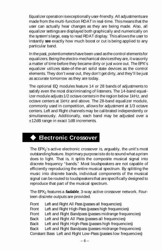
◆ Electronic Crossover
The EPX2's active electronic crossover is, arguably, the unit's mostoutstanding feature. Its primary purpose is to do to sound what a prismdoes to light. That is, it splits the composite musical signal intodiscrete frequency “bands.” Most loudspeakers are not capable ofefficiently reproducing the entire musical spectrum. By splitting themusic into discrete bands, individual components of the musicalsignal can be routed to loudspeakers that are specifically designed toreproduce that part of the musical spectrum.
The EPX2 features a fadable, 3-way active crossover network. Four-teen discrete outputs are provided.
Front Left and Right All Pass (passes all frequencies)Front Left and Right High-Pass (passes high frequencies)Front Left and Right Bandpass (passes midrange frequencies)Back Left and Right All Pass (passes all frequencies)Back Left and Right High-Pass (passes high frequencies)Back Left and Right Bandpass (passes midrange frequencies)Constant Bass Left and Right Low-Pass (passes low frequencies)

– 7 –
◆ Remote Data Access Terminal (RDAT)
The crossover points for high-pass, bandpass, and low-pass may beadjusted independently. (All pass outputs do not have crossoverpoints.) The most flexible feature is that crossover point adjustmentsmay be made in real time. With the EPX2, crossover points can bedynamically adjusted while listening. In addition, the user is notlimited to the handful of crossover points offered by most crossovermanufacturers. Each filter in the EPX2 can be set to 1 of 256 possiblefrequencies, for a total of 72,057,594,000,000,000 (72 quadrillion)unique crossover combinations.
All crossover points are represented both graphically and numericallyon the LCD display of the RDAT. High-Pass, Bandpass, and Low-Passtransfer functions are realistically simulated on a calibrated logarith-mic frequency scale. The exact crossover frequency is displayednumerically.
The EPX2 features a fadable crossover with constant bass low-passoutputs. It has outputs for both the Front and Rear of the system. Frontand Rear crossover settings for these outputs can be adjusted indepen-dently. A fadable crossover allows the user to fade the system fromfront to back for just the right amount of front stage / rear fill. Theconstant bass low-pass outputs provide low-pass information regard-less of the position of the fader.
The RDAT makes the EPX2 a unique and powerful signal processor.The RDAT is, in reality, a very powerful computer. It coordinates theoperation of the power supply, preamp, equalizer, and crossoversections of the EPX2, so that they all work together in perfect harmony.
The RDAT also provides the all-important link with the user. Toensure ease of operation, a menu driven software architecture wasselected for the user interface. In this type of system, options arepresented to the user on the RDAT's large 40 character by 2 linedisplay. To select a particular option, the user simply presses thefunction key that corresponds to the desired menu selection.
The RDAT contains a 16 bit microcontroller that runs at 20mHz. It hasa program capacity of 32k bytes and an 8k byte bank of nonvolatilestorage (saves settings when disconnected from the battery). Since allsoftware is written in assembly language, program coding is tight andperformance is optimal.

– 8 –
The communications interface provides the communications linkbetween the RDAT and the EPX2 unit. It accomplishes this task byusing RS-232 serial interface circuitry on all lines carrying data.Furthermore, to maintain ground isolation, all data lines are opticallyisolated from the EPX2's audio circuitry.
The first goal of Symmetry EPX2 was to offer a great equalizer,crossover and preamplifier all contained in one unit controlled by theRDAT. With that goal achieved, the second goal was to make the unitsoftware driven allowing each of those components to interact withone another.
After achieving the second goal the Rockford Fosgate design teamgave the EPX2 Global and VDISC features. These features worktogether and are very simple to operate. The global feature allows youto save all equalizer-crossover-preamp settings to one preset. Thereare four global presets. The VDISC feature, which stands for VolumeDependent Interactive System Control, allows you to toggle betweendifferent global presets based on the user specified volume thresh-olds.
◆ Communications Interface
◆ Global and VDISC Features

< <
<
< <
1 2 3 ESC
4 5 6 ➥
7 8 9 0<
MUTE
*SYMMETRY*PREAMP EQ GLOBAL LOCKXOVER
EPX2 DESIGN FEATURES
Remote Data Access Terminal
- 9 -
MultipurposeKeys
Numeric Keys
LCD Display: Menu selections and other vital system information aredisplayed in this area.
Function Keys: The function keys are used to select options displayedon the LCD display.
Escape Key: The ESC key is used to cancel a function or return to theprevious menu.
Volume Keys: These keys are used to control the system volume leveland mute.
Numeric Keys: These keys are used for entering numeric data.
Multipurpose These keys are used for various operations. See BasicOperation for additional information.
Enter Key: This key is reserved for future applications.
Escape KeyFunction KeysLCD Display
Enter KeyVolume Keys
Keys:

EPX2 Input Section
- 10 -
Power LED: The LED gives a visual indication of the status of theEPX2, lighting when the unit is turned on.
RCA Input Jacks: The industry standard RCA jack provides an easyconnection for signal level input. They are gold-platedto resist the signal degradation caused by corrosion.
Balanced Line This input will allow the optional Balanced Line Trans-mitter to be used in conjunction with the EPX2 toprovide better noise rejection. The Balanced LineTransmitter converts standard RCA signals to balancedline inputs.
RDAT Interface: The RJ11 connector is used to provide an easy 1 cablehook-up for the Remote Data Access Terminals.
Connector:
EPX2 Output Section
BP Output: The crossover signals from these outputs are Bandpassfrequencies. The crossover frequency is adjustablethrough the RDAT.
HP Output: The crossover signals from these outputs are High-Passfrequencies. The crossover frequency is adjustablethrough the RDAT.
AP Output: The signals from these outputs bypass the internalcrossover and are All-Pass (Full Range) frequencies.
LP Output: The crossover signals from these outputs are constantLow-Pass frequencies. The crossover frequency is ad-justable through the RDAT.
POWER Balanced RDAT
GNDB+REM
INPUT A INPUT B
Balanced
BACK FRONT
LEFT
RIGHT
BP HP AP LP BP HP AP
LEFT
RIGHT

INSTALLATION CONSIDERATIONS
Tools NeededThe following is a list of tools you will need for installing the EPX2.
Allen wrench 3/32" (included) VoltmeterWire strippers Battery post wrenchElectric hand drill w/assorted bits Wire cutters1kHz tone recorded at “all bits high” (opt.)
This section focuses on some of the vehicle considerations forinstalling your new EPX2. Checking your battery and present soundsystem, as well as pre-planning your system layout and best wiringroutes will save installation time. When deciding how to lay out yournew system, be sure that each component will be easily accessible formaking adjustments.
Before beginning any installation, be sure to follow these simple rules:
1. Be sure to carefully read and understand the instructions beforeattempting to install the EPX2.
2. For safety, disconnect the negative lead from the battery prior tobeginning the installation.
3. For easier assembly, we suggest you run all wires prior tomounting your EPX2 in place.
4. Route all of the RCA cables close together and away from anyhigh current wires.
5. Use high quality connectors for a reliable installation and tominimize signal or power loss.
6. Think before you drill! Be careful not to cut or drill into gas tanks,fuel lines, brake or hydraulic lines, vacuum lines or electricalwiring when working on any vehicle.
7. Never run wires underneath the vehicle. Running the wiresinside the vehicle provides the best protection.
8. Avoid running wires over or through sharp edges. Use rubber orplastic grommets to protect any wires routed through metal,especially the firewall.
9. ALWAYS protect the battery and electrical system from damagewith proper fusing. Install a fuseholder and fuse on the +12Vpower wire within 18” (45.7 cm) of the battery terminal.
10. When grounding to the chassis of the vehicle, scrape all paintfrom the metal to ensure a good, clean ground connection.Grounding connections should be as short as possible and alwaysbe connected to metal that is welded to the main body, or chassis,of the vehicle.
-11 -
MOUNTING LOCATIONS
The mounting location of your EPX2 main housing and RDAT willhave a great effect on the performance of your system. To provideproper ventilation the EPX2 should be mounted vertically wheneverpossible.
Trunk MountingMounting the EPX2 main housing in the trunk is sufficient. Leaveadequate room for the connection of cables and be careful not tomount the unit near any vehicle computers or sources of high voltage.Mounting the RDAT in the trunk does not allow for convenient accessand is not recommended.
Passenger Compartment MountingMounting the EPX2 main housing in the passenger compartment is anadequate location. Leave sufficient room for the connection of cablesand be careful not to mount the unit near any vehicle computers orsources of high voltage. Mount the RDAT in a location that providesthe user with easy access. Do not expose the RDAT to water, extremeheat, or direct sunlight.
Engine Compartment MountingThe Rockford Fosgate EPX2 main housing and RDAT should never bemounted in the engine compartment. Not only will this void yourwarranty but could create an embarrassing situation caused by theridicule from your friends.
-12 -
WIRING THE SYSTEM
1. Connect the EPX2 power cableThe B+ lead should be connected to a source of non-switched 12volts DC. Prepare the length of cable from the constant +12V bystripping 3/8" of insulation from the end of the wire. Insert thebared wire into the B+ terminal of the power connector and fastenthe screw. The total current consumption through this lead isapproximately 2 amps.
NOTE: The B+ cable MUST be fused 18" or less from the vehicle'sbattery. Install a fuse holder, along with a 3 amp fuse, under thehood and prepare the cable ends as stated above. Connectionsshould be water tight.

-13 -
The REM input lead should be connected to the remote turn-onor power antenna output from the source unit. Prepare the lengthof cable from the source of switched voltage by stripping 3/8" ofinsulation from the end of the wire. Insert the bared wire into theREM terminal of the power connector and fasten the screw. Totalcurrent consumption through this lead is negligible.
The GND lead should be connected to the chassis ground of thevehicle. Prepare a length of cable (approximately 12" long) to beused for the ground lead by stripping 3/8" of insulation from eachend. Insert one end of bared wire into the GND terminal of thepower connector and fasten the screw. Prepare the chassis groundby scraping any paint from the metal surface and thoroughly cleanthe area of all dirt and grease. Strip the other end of the wire andattach a ring connector. Fasten the cable to the chassis using ascrew.
After all three wires are securely fastened, insert the powerconnector into the EPX2 power socket.
2. Connect the RDAT to the EPX2 with the modular cableImportant! The modular cable is NOT a standard phone cable. Itis a 6 conductor non-flipped cable as opposed to the 4 conductorflipped cable used for telephone applications. Using a standardphone cable with the EPX2 will damage the unit and void yourwarranty.
3. Connect the source inputsConnect the front RCA outputs from the source unit to the desiredsource input on the EPX2. Since fade functions take place in theEPX2, only front outputs from the source unit are required.
If using the optional Balanced Line Transmitter, remove the coverfrom the main housing with the supplied Allen wrench. Locateand configure the signal input jumpers (J1, J2, J4, J5) to accept abalanced line input. Replace the cover on the main housing andconnect the RCAs from the source unit to the BLT input. Attach themini-DIN cable to the BLT and to the desired source input on theEPX2. For more detailed instructions refer to Page 41 of thismanual.
4. Connect the outputsConnect the appropriate outputs from the EPX2 to the appropriateinputs on the amplifiers.

-14 -
5. Verify operationPower the system up by turning on the source unit. After a fewseconds, the RDAT should display the Main Menu. Keep thevolume low until the correct crossover points are set.
6. Adjust EPX2 crossover settingsAdjust the EPX2 crossover points to the desired crossover frequen-cies. To access the crossover functions, select XOVER from theMain Menu. Then select the crossover section you wish to set up.
7. Adjust system levelsGo through the EPX2 level setting procedure. Select Setup fromthe Main Menu and then select Levels. Follow the instructionsgiven on the screen.
POWERBALANCED
BA
RDAT
GNDB+REM
BALANCEDINPUT A INPUT B
ModularCable
< <
<
< <
1 2 3 ESC
4 5 6 ➥
7 8 9 0<
MUTE
*SYMMETRY*PREAMP EQ GLOBAL LOCKXOVER
+ –
EPX2 BASIC CONNECTIONS
Connect to B+of battery with a
3 Amp fuse.
Connect to chassisground of vehicle.
Connect to remoteturn-on lead of
source unit.
Less than 18"
Power Connections

-15 -
RCA & RDAT Connections
• RCAs from source 1 are connected to “INPUT A.”• RCAs from source 2 are connected to “INPUT B.”• RDAT with cable is connected to “RDAT” input.• Gain is adjustable in SETUP / LEVELS menu.
POWER
BA
RDAT
GNDB+REM
BALANCEDINPUT B
< <
<
< <
1 2 3 ESC
4 5 6 ➥
7 8 9 0<
MUTE
*SYMMETRY*PREAMP EQ GLOBAL LOCKXOVER
INPUT ABALANCED
AUD SEL
1 2 3 4 5 6
RDMRPTSCAN PAUSED.SCN DIM
AMFMCh
RPTLD RDMDISC
ST P.SCN LOUDDSPL
R
CLOCK ILLUM
PWR
AUTO
® ®
VOL TUNE
-16 -
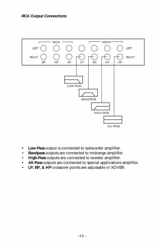
RCA Output Connections
BACK FRONT
LEFT
RIGHT
BP HP AP LP BP HP AP
LEFT
RIGHT
LOW-PASS
BANDPASS
HIGH-PASS
ALL-PASS
• Low-Pass output is connected to subwoofer amplifier.• Bandpass outputs are connected to midrange amplifier.• High-Pass outputs are connected to tweeter amplifier.• All-Pass outputs are connected to special applications amplifier.• LP, BP, & HP crossover points are adjustable in XOVER.

-17 -
B A S I C O P E R AT I O N
The RDAT provides the link with the user. To ensure ease of operation,a menu driven software architecture was selected for the user inter-face. In this type of system, options are presented to the user on theRDAT's large 40 character by 2 line display. To select a particularoption, the user presses the function key that corresponds to thedesired menu selection.
Main Menu
The display shown above is a representation of the EPX2 main menu.The “>” symbol located in the upper right corner of the LCD displayindicates that there are additional menu commands available. Toaccess these commands, press the right “>” multipurpose key. Thedisplay will change as follows.
* SYMMETRY *
PREAMP EQ XOVER GLOBAL LOCK
* SYMMETRY *
SETUP ABOUT
<
To return to the previous selections, press the left “<” multipurposekey or the ESC key.
>
-18 -
PREAMP OPERATION
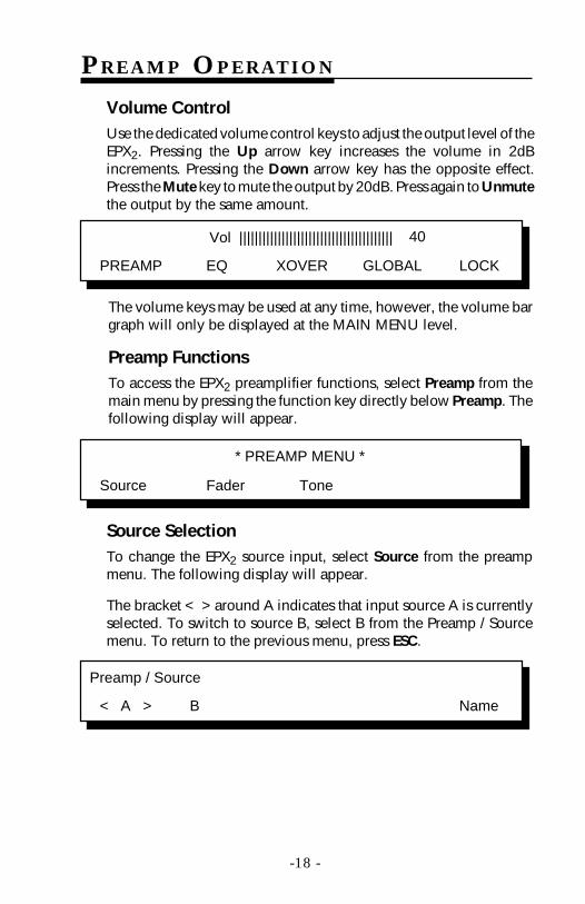
Volume ControlUse the dedicated volume control keys to adjust the output level of theEPX2. Pressing the Up arrow key increases the volume in 2dBincrements. Pressing the Down arrow key has the opposite effect.Press the Mute key to mute the output by 20dB. Press again to Unmutethe output by the same amount.
PREAMP EQ XOVER GLOBAL LOCK
Vol |||||||||||||||||||||||||||||||||||||||| 40
The volume keys may be used at any time, however, the volume bargraph will only be displayed at the MAIN MENU level.
Preamp FunctionsTo access the EPX2 preamplifier functions, select Preamp from themain menu by pressing the function key directly below Preamp. Thefollowing display will appear.
Preamp / Source
< A > B Name
Source SelectionTo change the EPX2 source input, select Source from the preampmenu. The following display will appear.
The bracket < > around A indicates that input source A is currentlyselected. To switch to source B, select B from the Preamp / Sourcemenu. To return to the previous menu, press ESC.
* PREAMP MENU *
Source Fader Tone

-19 -
PREAMP OPERATION
Source NameTo name the source, first select which Source is to be named (A or B),then select Name. The following will be displayed.
Use arrow keys to change source name.
[ A ] B
Use the left/right multipurpose keys to select cursor position and theup/down multipurpose keys to select characters. Upon completion,press the corresponding function key.
Fader Control
To adjust the EPX2 fader control, select Fader from the preamp menu.The following display will appear.
Balance Fader
To adjust the Left/Right Balance, use the left/right multipurpose keys.To adjust the Front/Back Fader, use the up/down multipurpose keys.To reset Balance and Fader to their default positions, press the centermultipurpose key. To return to the previous menu, press ESC.
Tone Control
To adjust the EPX2 tone controls, select Tone from the preamp menu.The following display will appear.
The bracket < > around 45Hz indicates that the 45Hz tone controlis currently selected. Use the left/right multipurpose keys to switchbetween the two tone controls.
Use the up/down multipurpose keys to boost or cut the currentlyselected tone control. Press the center multipurpose key to set bothtone controls to their neutral (flat) positions. To return to the previousmenu, press ESC.
F |||||||||||||||||||||||||||||||||||||||| B
< 45 Hz > 15 kHz
– |||||||||||||||||||||||||||||||||||||||| + – |||||||||||||||||||||||||||||||||||||||| +
L |||||||||||||||||||||||||||||||||||||||| R

- 20 -
EQUALIZER OPERATION (optional accessory)
Eq / Load
BANK A BANK B BANK C BANK D Adjust
Load EQ Preset
To load a previously saved equalizer preset, simply select whichBANK of presets to be recalled by pressing its corresponding functionkey. After selecting which Bank of presets to load, the followingoptions will be displayed.
Eq / Load
< A > B C D Adjust
To select the Preset to be loaded, press the corresponding functionkey. For example, to load preset “A” under “BANK A”, press thefunction key directly below “BANK A” and then press the functionkey directly below “A.”
The bracket < > around a Bank or Preset indicates that selection iscurrently selected. To load another preset, press the desired preset'scorresponding function key. To return to the previous menu, pressESC.
To access the EPX2 equalizer functions, select EQ from the mainmenu. The following display will appear.
NOTE: One of the optional equalizers (SYM-E14 or SYM-E28) mustbe installed prior to equalizer operation. Refer to pages 38 and 39 forhardware installation and page 36 for software installation.

- 21 -
EQUALIZER OPERATION (optional accessory)
250 Hz L=R
0 dB | | | | | | | | | | | | | | Save
NOTE: The display shown above represents the SYM-E14 equalizergraph.
Use the left/right multipurpose keys to select the desired band. Thecurrently selected band is indicated with an underscore character“_”. The frequency of the currently selected band is displayednumerically in the top left of the LCD display.
Use the up/down multipurpose keys to boost or cut the selectedband. The exact amount of boost or cut for the currently selected bandis displayed numerically in the lower left of the LCD display.
To set the currently selected band to “Flat”, momentarily press thecenter multipurpose key. To set all equalizer bands to “Flat,” pressand hold the center multipurpose key. To return to the previousmenu, press the ESC key.
EQ AdjustTo manually adjust the EPX2 equalizer, select EQ from the main menuand then select Adjust from the Eq/Load menu. The following displaywill appear.
Select Left to adjust the equalizer's left channel or Right to adjust theequalizer's right channel. (Left and Right equalizer settings can be setindependently.) Selecting Both will allow the left and right equalizerchannels to be adjusted simultaneously. The following screen will bedisplayed.
Select channel to Adjust …
Left Right Both

Save Curve / Change Name
To save the previously set EQ curve, select Save. The followingoptions will be displayed.
- 22 -
EQUALIZER OPERATION (optional accessory)
Eq / Adjust / Save
BANK A BANK B BANK C BANK D
Press the corresponding function key under the desired Bank. Afterselecting which Bank will store the curve, the name of the selectedBank can now be changed.
The underscore “–” shows cursor position. Use the left/right multi-purpose keys to position the cursor and the up/down multipurposekeys to select characters. After changing the name, press the corre-sponding function key and the following will display.
Eq / Adjust / Save
A B C D
Now select the Preset that the curve is to be saved at. After selectingwhich Preset will store the curve, the name of the selected Preset canbe changed. Similar to naming the Bank, use the left /right multipur-pose keys to select cursor position and the up/down multipurpose keyto select characters.
EQ1
BANK A BANK B BANK C BANK D
PRESET APRESET BPRESET CPRESET D
PRESET APRESET BPRESET CPRESET D
PRESET APRESET BPRESET CPRESET D
PRESET APRESET BPRESET CPRESET D
EQUALIZER PRESET FLOW CHART
EQ

- 23 -
To adjust the EPX2 active electronic crossover, select XOVER from themain menu. The following options will be displayed.
Low-Pass Adjustment
To access the crossover's low-pass section, select LP from thecrossover menu. The following screen will be displayed.
* CROSSOVER MENU *
LP BP HP
F3 = 200 20 200 2K 20K
CROSSOVER OPERATION
In the display above, F3 indicates the currently selected low-passcrossover frequency in Hz. The crossover frequency is also repre-sented graphically on a 20Hz-20kHz log scale.
To adjust the low-pass crossover point, use the left/right multipur-pose keys. Press ESC to return to the previous menu. Changes will besaved automatically.

- 24 -
Bandpass Adjustment
To access the crossover's bandpass section, select BP from thecrossover menu. The following options will be displayed.
Xover / BP
Back Front
F3 = 200 20 200 2K 20K
Select Back to adjust the crossover's back bandpass section or Frontto adjust the front bandpass section. (Front and Back crossoversettings are totally independent.) The following screen will be dis-played.
The bandpass section has two separate crossover frequency settings.The first determines the low-side cutoff frequency and the seconddetermines the high-side cutoff frequency. The EPX2 allows the userto adjust each of these crossover frequencies independently.
To adjust the low-side frequency, press the Far Left function key. Thecurrent low-side crossover frequency will be displayed numericallyas F3 in the top left corner of the LCD display. Use the left/rightmultipurpose keys to adjust the low-side crossover frequency.
To adjust the high-side frequency, press the Far Right function key.The current high-side crossover frequency will be displayed numeri-cally as F3 in the top left corner of the LCD display. Use the left/rightmultipurpose keys to adjust the high-side crossover frequency.
CROSSOVER OPERATION
Lo Side

- 25 -
CROSSOVER OPERATION
Xover / HP
Back Front
F3 = 200 20 200 2K 20K
Select Back to adjust the crossover's back high-pass section or Frontto adjust the front high-pass section. (Front and Back crossoversettings are totally independent.) The following screen will be dis-played.
In the display above, F3 indicates the currently selected high-passcrossover frequency in Hz. The crossover frequency is also repre-sented graphically on a 20Hz-20kHz log scale.
To adjust the high-pass crossover point, use the left/right multipur-pose keys. Press ESC to return to the previous menu. Changes will besaved automatically.
High-Pass Adjustment
To access the crossover's high-pass section, select HP from thecrossover menu. The following screen will be displayed.

- 26 -
GLOBAL OPERATION
Global Preset / Load
< A > B C D
The bracket < > around A indicates that global preset A is currentlyselected. To load another preset, press the corresponding functionkey. To return to the previous menu, press ESC.
* GLOBAL PRESET MENU *
Load Save VDISC
Global Load
To load a previously saved global preset, select Load from the globalpreset menu. The following options will be displayed. Next, press thefunction key that corresponds to the preset you would like to load. Forexample, if you would like to load global preset “A”, you would pressthe function key directly below “A”.
The EPX2 Global Preset functions allow the user to…
• Save all Source-EQ-Preamp-Crossover settings toone global preset.
• Recall all system settings from one of four presets
• Automatically toggle between presets A & B withvolume control (VDISC)
• Automatically toggle between presets B & C withvolume control (VDISC)
• Automatically toggle between presets C & D withvolume control (VDISC)
To access the global preset functions, select Global from the mainmenu. The following options will be displayed.

GLOBAL OPERATION
- 27 -
Global Save / Change Name
To save all system settings to a global preset:1. Select desired Source input to be used from the Preamp/Source
menu.
2. Select desired EQ curve from the EQ Bank of Presets (RTA curve,SPL curve).
3. Select desired Tone/Fader settings from the Preamp menu.
4. Select desired Crossover settings from the XOVER menu.
Once all system settings are adjusted, select Save from the globalpreset menu. The following options will be displayed.
Global Preset / Save
< A > B C D
Use arrow keys to change global name
[ A ] B C D
Select the preset of the desired settings to be saved and press thecorresponding function key. The following will be displayed.
The name of the global preset can now be changed. Use the left/rightmultipurpose keys to select cursor position and the up/down multi-purpose keys to select characters. To return to the previous menupress ESC.
GLOBAL OPERATION
- 28 -
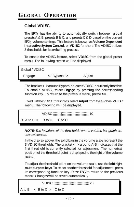
Global VDISC
The EPX2 has the ability to automatically switch between globalpresets A & B, presets B & C, and presets C & D based on the currentEPX2 volume settings. This feature is known as Volume DependentInteractive System Control, or VDISC for short. The VDISC utilizes3 thresholds for its switching process.
To enable the VDISC feature, select VDISC from the global presetmenu. The following screen will be displayed.
Global / VDISC
Engage < Bypass > Adjust
The bracket < >around Bypass indicates VDISC is currently inactive.To enable VDISC, select Engage by pressing the correspondingfunction key. To return to the previous menu, press ESC.
To adjust the VDISC thresholds, select Adjust from the Global / VDISCmenu. The following will be displayed.
< A to B > B to C C to D
NOTE: The locations of the thresholds on the volume bar graph areuser selectable.
In the display above, the solid bars in the volume scale represent the3 VDISC thresholds. The bracket < > around A-B indicates that thefirst threshold is currently selected for adjustment. The numericalposition of the threshold point is displayed to the right of the volumescale.
To adjust the threshold point on the volume scale, use the left/rightmultipurpose keys. To select another threshold for adjustment, pressits corresponding function key. Press ESC to return to the previousmenu. Changes will be saved automatically.
A to B < B to C > C to D
VDISC |||||||||||||||||||||||||||||||||||||||| 10
VDISC |||||||||||||||||||||||||||||||||||||||| 20
GLOBAL OPERATION
- 29 -
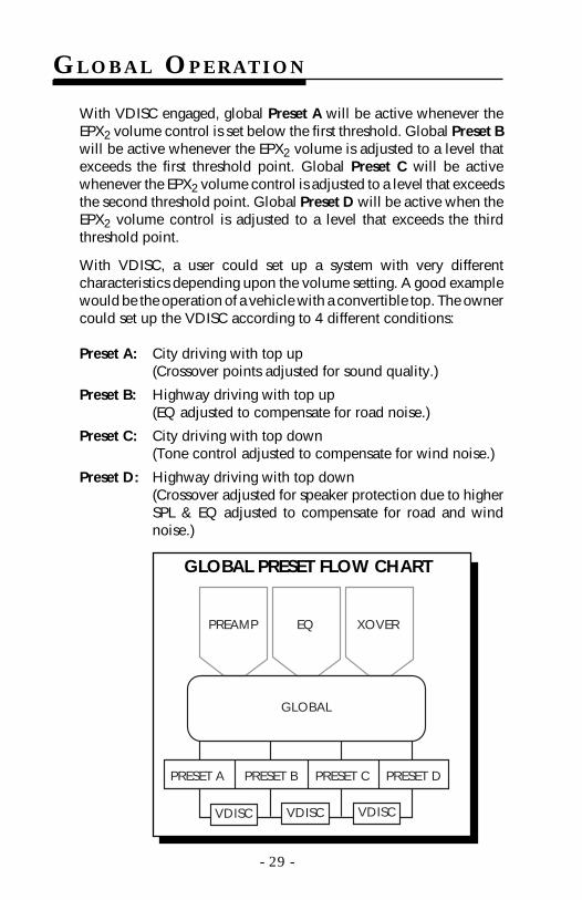
With VDISC engaged, global Preset A will be active whenever theEPX2 volume control is set below the first threshold. Global Preset Bwill be active whenever the EPX2 volume is adjusted to a level thatexceeds the first threshold point. Global Preset C will be activewhenever the EPX2 volume control is adjusted to a level that exceedsthe second threshold point. Global Preset D will be active when theEPX2 volume control is adjusted to a level that exceeds the thirdthreshold point.
With VDISC, a user could set up a system with very differentcharacteristics depending upon the volume setting. A good examplewould be the operation of a vehicle with a convertible top. The ownercould set up the VDISC according to 4 different conditions:
Preset A: City driving with top up(Crossover points adjusted for sound quality.)
Preset B: Highway driving with top up(EQ adjusted to compensate for road noise.)
Preset C: City driving with top down(Tone control adjusted to compensate for wind noise.)
Preset D: Highway driving with top down(Crossover adjusted for speaker protection due to higherSPL & EQ adjusted to compensate for road and windnoise.)
GLOBAL
PRESET A PRESET B PRESET C PRESET D
PREAMP EQ XOVER
VDISC VDISC VDISC
GLOBAL PRESET FLOW CHART
LOCK OPERATION
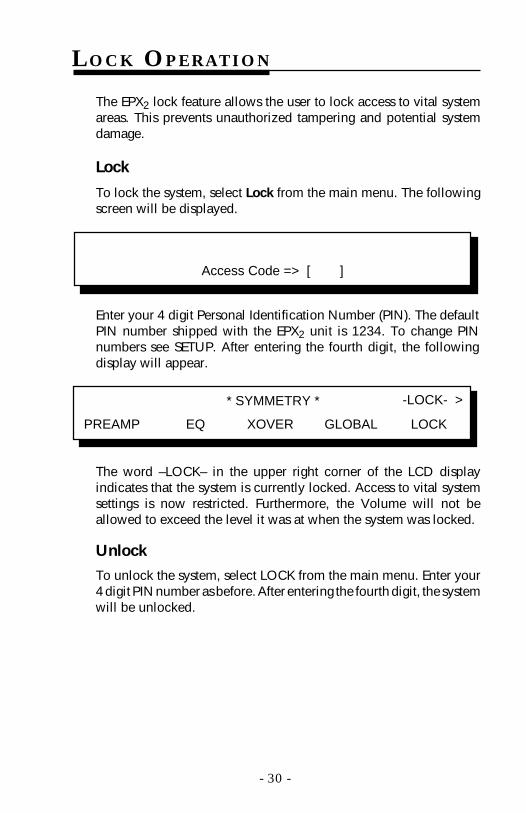
The EPX2 lock feature allows the user to lock access to vital systemareas. This prevents unauthorized tampering and potential systemdamage.
Lock
To lock the system, select Lock from the main menu. The followingscreen will be displayed.
Access Code => [ ]
- 30 -
Enter your 4 digit Personal Identification Number (PIN). The defaultPIN number shipped with the EPX2 unit is 1234. To change PINnumbers see SETUP. After entering the fourth digit, the followingdisplay will appear.
The word –LOCK– in the upper right corner of the LCD displayindicates that the system is currently locked. Access to vital systemsettings is now restricted. Furthermore, the Volume will not beallowed to exceed the level it was at when the system was locked.
Unlock
To unlock the system, select LOCK from the main menu. Enter your4 digit PIN number as before. After entering the fourth digit, the systemwill be unlocked.
* SYMMETRY *
PREAMP EQ XOVER GLOBAL LOCK
-LOCK- >

To access the Setup Menu, select Setup from the Main Menu. Thefollowing options will be displayed.
* SETUP MENU *
Chirp Code Language Levels Light
SETUP OPERATION
- 31 -
>
* SETUP MENU *
Memory D-Card
The bracket < > around Yes indicates that the chirp feature is cur-rently active. To disable this feature, select No. The display will thenrevert back to the Setup Menu.
To re-enable the chirp feature, or to change the pitch of the chirp,select Chirp from the Setup Menu. The following options will bedisplayed.
<
Chirp
The Chirp option allows the user to enable or disable the soundsgenerated by the RDAT. To access this function, select Chirp from theSetup Menu. The following options will be displayed.
Setup / Chirp - Enable keyboard chirp?
< Yes > No
Setup / Chirp - Enable keyboard chirp?
Yes < No >
To access the next menu of commands, press the right “>” multipur-pose key. The display will change as follows.

SETUP OPERATION
- 32 -
Setup / Chirp / Pitch Control
Press UP/DN arrow keys to adjust pitch.
Press the up/down multipurpose keys to adjust the pitch of the chirp.Pressing the center multipurpose key will reset the chirp pitch to itsfactory default position. Press ESC to return to the Setup Menu.
Enter your 4 digit Personal Identification Number (PIN). The defaultPIN number shipped with the EPX2 unit is 1234. The display willchange to show the following.
This indicates that your new PIN number was accepted. Do not forgetyour code.
Setup / Change Access Code
NEW ACCESS CODE ACCEPTED
Select Yes. The screen will then display the following.
Code
The code option allows the user to define his/her Personal Identifica-tion Number (PIN). To access this feature, select Code from the SetupMenu. The following screen will be displayed.
Setup / Change Access Code
Enter New Access Code => [ ]
Setup / Change Access Code
Enter Old Access Code => [ ]
Enter your personalized 4 digit PIN number. (You choose the code.)After entering the fourth digit, you will be asked to re-enter your newPIN number for verification purposes. After successfully entering thesame number twice, the display will change to show the following.

SETUP OPERATION
- 33 -
Language
This option is used to select the default language that will be displayedon the RDAT LCD. To access this function, select Language from theSetup Menu. The following options will be displayed.
Setup / Language - Select default
< Englsh > French German Itlian Spnish
The bracket < > around English indicates that the English languageis currently selected. To select another language to be displayed,press the corresponding function key. To return to the previous menu,press ESC.
Levels
This feature is used during the initial installation of your EPX2 forproper input gain settings, maximizing noise floor, and prevent signalclipping. To access this function, select Levels from the Setup menu.The following screen will be displayed.
Select Source To Setup
< A > B
The EPX2 has the ability to step the user through the level settingprocedures during the initial installation of the unit. To access thisfunction, select Assist from the LEVELS menu and follow the direc-tions on the screen.
To adjust the level setting manually, select Manual. The followingscreen will be displayed.
Setup / Levels - Please select method.
Assist Manual Track
The bracket < > around A indicates that input source A is currentlyselected. To adjust source B, select B from the Levels / Manual menu.After selecting the source, the following screen will appear.

SETUP OPERATION
- 34 -
The bracket > next to L & R indicates that the left and right channelsare currently selected for simultaneous adjustment. To increase theleft and right channel gain, use the right multipurpose key.Todecrease the left and right channel gain, use the left multipurposekey.
The left and right Gain control may be adjusted individually by usingthe up/down multipurpose keys. To adjust the Left channel gain, pressthe up “^” multipurpose key.
The bracket > next to L indicates that the left channel is currentlyselected for adjustment. To increase the left channel gain, use theright multipurpose key. To decrease the left channel gain, use the leftmultipurpose key. To adjust the Right channel gain, press the down“v” multipurpose key.
The bracket > next to R indicates that the right channel is currentlyselected for adjustment. To increase the right channel gain, use theright multipurpose key. To decrease the right channel gain use theleft multipurpose key.
After the Gain has been properly adjusted for both the left and rightchannels, press ESC to return to the previous menu.
> L |||||||||||||||||||||||||||||||||||||||||||||||||||||||||||||||||||||||||||||||||||| 128> R |||||||||||||||||||||||||||||||||||||||||||||||||||||||||||||||||||||||||||||||||||| 128
> L |||||||||||||||||||||||||||||||||||||||||||||||||||||||||||||||||||||||||||||||||||| 141 R |||||||||||||||||||||||||||||||||||||||||||||||||||||||||||||||||||||||||||||||||||| 128
L |||||||||||||||||||||||||||||||||||||||||||||||||||||||||||||||||||||||||||||||||||| 128> R |||||||||||||||||||||||||||||||||||||||||||||||||||||||||||||||||||||||||||||||||||| 135

SETUP OPERATION
- 35 -
To access the EQ Tracking feature select Track from the Setup/Levelsmenu. The following screen will be displayed.
Setup / Levels / EQ Tracking
Engage < Bypass >
The bracket < > around Bypass indicates the EQ Tracking feature iscurrently inactive. To enable EQ Tracking, select Engage by pressingthe corresponding function key.
The EQ tracking feature monitors the optional E14/E28 DCard equal-izer to prevent signal clipping or distortion. When any frequency onthe equalizer is boosted, the overall input gain of the EPX2 automati-cally re-adjusts itself just under clipping level.
NOTE: The levels must be adjusted prior to engaging the EQ Trackingusing Assist or Manual from The levels menu. EQ Tracking is onlybeneficial when using an optional E14 or E28 DCard.
Light
This option is used to select the backlit status of the RDAT.
The bracket < > around “On” indicates that the illumination featureis currently active. To disable this feature, select “Off”. Temporaryillumination can be enabled by selecting “Auto”. Within a 1 minutetime frame, if no keys are touched, the illumination will turn off.
Setup / Light: Select backlight status.
< On > Off Auto
Memory
This option is used to reset all system presets to their default factorysettings. To access this function, select Memory from the Setup Menu.The following options will be displayed.
Restore presets to factory defaults?
Yes < No >
Select Yes to reset all system presets. Select No or ESC to cancel andreturn to the Setup Menu.

- 36 -
DCard
This option is used to adapt the software when installing or un-installing optional DCard modules into the EPX2 main housing. Toadapt DCard software, select D-Card from the Setup menu. Thefollowing will be displayed.
Setup / D-Card: Select options.
E14 [ * ] E28 [ ]
The asterisk * inside the E14 brackets [ ] indicates that the E14software is currently installed and adapted. If installing an E28equalization module, select E28 by pressing the correspondingfunction key.
When un-installing optional modules in the EPX2 main housing, theDCard software may be disabled by pressing the correspondingfunction key again. The asterisk will then be removed from thebrackets. To return to the previous menu, press ESC.
*SYMMETRY*was created by WAYNE HARRIS
*SYMMETRY*EPX BIOS: __•_____
A few moments later the screen will automatically change to thefollowing.
ABOUT OPERATION
The About function displays the software version currently installedin the RDAT. Since the EPX2 is software controlled, the program caneasily be updated as new features are developed. To access thisfunction, select About from the Main Menu. The following will bedisplayed.
ROCKFORD FOSGATE ACCESSORIES
The following accessories were designed to enhance the perfor-mance of the EPX2 and are available from your Authorized RockfordFosgate Dealer.
• 14-Band Graphic Equalizer (SYM-E14)The SYM-E14 is a 14-band graphic equalizer. This analog proces-sor adjusts frequencies centered at 30Hz, 45Hz, 60Hz, 90Hz,125Hz, 180Hz, 250Hz, 375Hz, 500Hz, 1kHz, 2kHz, 4kHz, 8kHz,and 16kHz with ±12dB of boost or cut. Equalization curves can beadjusted independently between left and right channels and can besaved to one of 16 namable presets.
• 28-Band Graphic Equalizer (SYM-E28)The SYM-E28 is a 28-band (1/3 octave) graphic equalizer. Thisanalog processor adjusts frequencies centered at 32Hz, 40Hz,50Hz, 63Hz, 80Hz, 100Hz, 125Hz, 160Hz, 200Hz, 250Hz,320Hz, 400Hz, 500Hz, 630Hz, 800Hz, 1kHz, 1.25kHz, 1.6kHz,2kHz, 2.5kHz, 3.25kHz, 4kHz, 5kHz, 6.3kHz, 8kHz, 10kHz,12.5kHz, and 16kHz with ±12dB of boost or cut. Equalizationcurves can be adjusted independently between left and rightchannels and can be saved to one of 16 namable presets. Addi-tional features include dual LED level meters. The E28 is availablefor the EPX2 signal processing system.
• Balanced Line Transmitter (FG-BLT)The Balanced Line Transmitter converts signal RCA cables from thesource unit to balanced signals. The BLT improves sound qualityin the system by eliminating noises generated by vehicle electricalsystems. The BLT is available for Rockford Fosgate products thatoffer a balanced input.
- 37 -

Installing the Optional SYM-E14
- 38 -
ATTENTION: To maintain your EPX2 warranty, we recommend yourAuthorized Rockford Fosgate Dealer install your new accessory.
E. Install E14 carefully into header connections P3, P4 and P5.F. Replace 2 Top Standoffs, with screws intact, carefully by hand.
(Do Not Overtighten.)G. Replace Cover on the main unit with the six hex head screws.H. Reconnect RDAT & Power to main unit.I. Adapt E14 Software by selecting DCard from the Setup menu and
select E14 or refer to page 36 of your EPX2 Manual.J. Congratulations! You have successfully installed your optional
Equalizer Module.
A. Disconnect RDAT & Power from the main unit.B. Remove Cover from main unit by unscrewing the six hex head
screws with the 3/32" Allen wrench supplied with the EPX2.C. Remove 2 Jumpers on connector P5 corresponding to LOL, LRL,
LOR & LRR.D. Remove the Top Half of the 2 Standoffs carefully by hand from
the main unit. It is not necessary to remove the top screws whenseparating the standoff into its two segments.
® ®
P4
P5
P3
B B
B
B
A
B
D C
D
™
P4
P5
P3
F
E
FEE
EE
E

- 39 -
Installing the Optional SYM-E28
® ®
P4
P5
P3
B B
B
B
A
B
D C
D
™
A. Disconnect RDAT & Power from the EPX2.
B. Remove Cover from main unit by unscrewing the six hex headscrews with the 3/32" Allen wrench supplied with the EPX2.
C. Remove 2 Jumpers on connector P5 corresponding to LOL, LRL,LOR & LRR.
D. Remove 2 Nylon Screws carefully from standoffs with a slottedscrewdriver.
E. Install 3 Header Extensions supplied with EQ carefully into P3,P4 and P5.
F. Install E28 carefully into header extensions P3, P4 and P5.
G. Replace 2 Nylon Screws carefully through EQ and secure intostandoffs with a slotted screwdriver. (Do Not Overtighten.)
H. Replace Cover on the main unit with the six hex head screws.
P4
P5
P3
G
F
G
HeaderExtension
HeaderExtension
HeaderExtension
E
EEF F

- 40 -
ATTENTION: To maintain your EPX2 warranty, we recommend yourAuthorized Rockford Fosgate Dealer install your new accessory.
I. Reconnect RDAT & Power to main unit.
J. Adapt E28 Software by selecting DCard from the Setup menu andselect E28 or refer to page 36 of your EPX2 Manual.
K. Congratulations! You have successfully installed your optionalEqualizer Module.

Installing the Optional Balanced Line Transmitter
- 41 -
POWER
GNDB+REM
INPUT A INPUT B
Balanced
A: Balanced Line InputB: RCA Input
Internal JumperConfiguration
Balanced
BLT(Optional)
RDAT
A
B GN
DG
ND
J3
J6
J1 J2
J4 J5
BAL
RCA
RCA
BAL
< <
<
< <
1 2 3 ESC
4 5 6 ➥
7 8 9 0<
MUTE
*SYMMETRY*PREAMP EQ GLOBAL LOCKXOVER
AUD SEL
1 2 3 4 5 6
RDMRPTSCAN PAUSED.SCN DIM
AMFMCh
RPTLD RDMDISC
ST P.SCN LOUDDSPL
R
CLOCK ILLUM
PWR
AUTO
® ®
VOL TUNE
• Remove Cover from main unit by unscrewing the six hex head screwswith the 3/32" Allen wrench supplied with the EPX2.
• Reconfigure Jumpers J1 & J2 (Input A) or J4 & J5 (Input B) to acceptbalanced line inputs (refer to drawing).
• RCAs from Source connected to Balanced Line Transmitter withminimal cable.
• Balanced Line Cable from BLT connected to “Balanced” input.
ATTENTION: To maintain your EPX2 warranty, we recommend your AuthorizedRockford Fosgate Dealer install your new accessory.

- 42 -
SYSTEM DIAGRAMS
BA
CK
FRO
NT
LEFT
RIG
HT
BP
HP
AP
AP
LEFT
RIG
HT
LPB
PH
P
Bac
kLo
w-P
ass
20H
z -1
00H
z
Twee
ter
100H
z-4k
Hz
Woo
fer
Woo
fer
Mid
rang
e
2-C
hann
elA
mpl
ifier
4-C
hann
elA
mpl
ifier
4kH
z-20
kHz
Fron
tH
igh-
Pass
Fron
tB
andp
ass
3-W
ay S
yste
m

- 43 -
BA
CK
FRO
NT
LEFT
RIG
HT
BP
HP
AP
LPB
PH
PA
P
LEFT
RIG
HT
Bac
kH
igh-
Pass
4kH
z-20
kHz
Twee
ter
100H
z-4k
Hz
Mid
rang
eM
idra
nge
4-C
hann
elA
mpl
ifier
4-C
hann
elA
mpl
ifier
4kH
z-20
kHz
Fron
tH
igh-
Pass
Fron
tB
andp
ass
Twee
ter
2-C
hann
elA
mpl
ifier
Woo
fer
Woo
fer
Bac
kB
andp
ass
100H
z-4k
Hz
Low
-Pas
s
20H
z-10
0Hz
Fada
ble
3-W
ay S
yste
m

- 44 -
4-W
ay S
yste
mB
AC
KFR
ON
T
LEFT
RIG
HT
BP
HP
AP
LPB
PH
PA
P
LEFT
RIG
HT
100H
z-65
0Hz
Fron
tH
igh-
Pass
Mid
-Bas
s
Twee
ters
Woo
fers
4kH
z-20
kHz
Bac
kB
andp
ass
Bac
kH
igh-
Pass
Fron
tB
andp
ass
Mid
rang
e
2-C
hann
elA
mpl
ifier
2-C
hann
elA
mpl
ifier
Twee
ters
4kH
z-20
kHz
650H
z-4k
Hz
20H
z-10
0Hz
Low
-Pas
s
2-C
hann
elA
mpl
ifier
2-C
hann
elA
mpl
ifier
2-C
hann
elA
mpl
ifier

- 45 -
Fada
ble
4-W
ay S
yste
mB
AC
KFR
ON
T
LEFT
RIG
HT
BP
HP
AP
LPB
PH
PA
P
LEFT
RIG
HT
4kH
z-2
0kH
z
Fro
nt
Hig
h-P
ass
Mid
-Bas
s
Twee
ter
and
Mid
ran
ge
Wo
ofe
r
27
5H
z-4
kHz
Bac
kH
igh
-Pas
s
Bac
kB
and
pas
sFr
on
tB
and
pas
s
2-C
han
nel
Am
pli
fier
*
4-C
han
nel
Am
pli
fier
2-C
han
nel
Am
pli
fier
4kH
z-2
0kH
z
27
5H
z-4
kHz
20
Hz-
10
0H
z
AP
4-C
han
nel
Am
pli
fier
2-C
han
nel
Am
pli
fier
Wo
ofe
r
2-C
han
nel
Am
pli
fier
*
*Uti
lize
in
tern
al a
mp
lifi
er c
ross
ove
r
20
Hz-
10
0H
z
AP
Twee
ter
and
Mid
ran
ge
Mid
-Bas
s
10
0H
z-2
75
Hz
LP*
10
0H
z-2
75
Hz
LP*
- 46 -
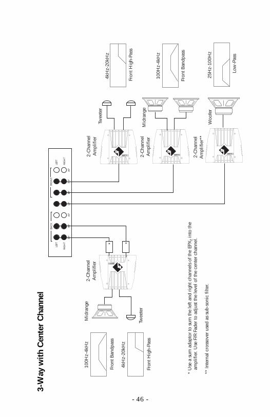
3-W
ay w
ith
Cen
ter
Cha
nnel
BA
CK
FRO
NT
LEFT
RIG
HT
BP
HP
AP
LPB
PH
PA
P
LEFT
RIG
HT
Fron
t Ban
dpas
s
100H
z-4k
Hz
Twee
ter
100H
z-4k
Hz
Mid
rang
e
Woo
fer
2-C
hann
elA
mpl
ifier
2-C
hann
elA
mpl
ifier
4kH
z-20
kHz
Fron
t Hig
h-Pa
ss
Fron
t Ban
dpas
s
Twee
ter
Fron
t Hig
h-Pa
ss
4kH
z-20
kHz
* U
se a
sum
ada
ptor
to s
um th
e le
ft an
d ri
ght c
hann
els
of th
e EP
X2
into
the
am
plifi
er. U
se F
/R F
ader
to a
djus
t the
leve
l of t
he c
ente
r ch
anne
l.
** In
tern
al c
ross
over
use
d as
sub
-son
ic fi
lter.
* *
Mid
rang
e2-
Cha
nnel
Am
plifi
er
2-C
hann
elA
mpl
ifier
**
25H
z-10
0Hz
Low
-Pas
s

TROUBLESHOOTING
Symptom Diagnosis Remedy
Voltage applied to theREM terminal is not be-tween 10.5 and 15.5volts or there is no volt-age present.
Voltage to the B+ termi-nal is not between 10.5and 15.5 volts or thereis no voltage present.
EPX2 is not properlygrounded.
Source is not properlyselected.
Signal from source is notconnected or function-ing properly.
When using the BLT,Balanced Line Inputfrom BLT is not con-nected or not function-ing properly.
RDAT is not processinginformation correctly.
RDAT cable is not fullyconnected.
Microprocessor isscrambled.
Check the alternator, bat-tery, fuse, and wiring andrepair as necessary. If thevoltage is above 15.5 volts,have the electrical systeminspected by an authorizedcar service center.
Check the alternator, bat-tery, fuse, and wiring andrepair as necessary. If thevoltage is above 15.5 volts,have the electrical systeminspected by an authorizedcar service center.
Check wiring and repair asnecessary.
EPX2 has no sound(Power LED is on)
Check Preamp Source andselect the correspondingsource input.
Check connections, substi-tute with known workingsource and cables and repairor replace as necessary.
Check connections, substi-tute with known working BLTand cables and repair or re-place as necessary.
Make sure no keys aredepressed on the RDAT.
Check cable connection andcorrect if necessary.
Disconnct power to the EPX2,then reconnect.
- 47 -
Keyboard doesn'trespond properly
Unit does notturn on(Power LED is off)
TROUBLESHOOTING
Symptom Diagnosis Remedy
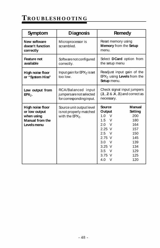
- 48 -
New softwaredoesn't functioncorrectly
Microprocessor isscrambled.
Software not configuredcorrectly.
Input gain for EPX2 is settoo low.
RCA/Balanced inputjumpers are not selectedfor corresponding input.
Source unit output levelis not properly matchedwith the EPX2.
Reset memory usingMemory from the Setupmenu.
Select DCard option fromthe setup menu
Readjust input gain of theEPX2 using Levels from theSetup menu.
Check signal input jumpers(J1, J2 & J4, J5) and correct asnecessary.
Source ManualOutput Setting1.0 V 2001.5 V 1802.0 V 1642.25 V 1572.5 V 1502.75 V 1453.0 V 1393.25 V 1343.5 V 1293.75 V 1254.0 V 120
Feature notavailable
High noise flooror “System Hiss”
Low output fromEPX2.
High noise flooror low outputwhen usingManual from theLevels menu
TROUBLESHOOTING
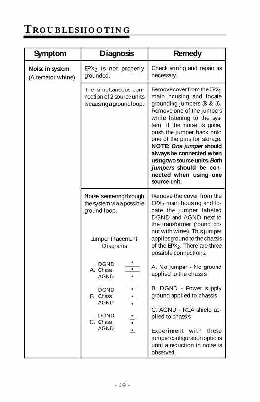
Symptom Diagnosis Remedy
- 49 -
Noise in system(Alternator whine)
Check wiring and repair asnecessary.
Remove cover from the EPX2main housing and locategrounding jumpers J3 & J6.Remove one of the jumperswhile listening to the sys-tem. If the noise is gone,push the jumper back ontoone of the pins for storage.NOTE: One jumper shouldalways be connected whenusing two source units. Bothjumpers should be con-nected when using onesource unit.
Remove the cover from theEPX2 main housing and lo-cate the jumper labeledDGND and AGND next tothe transformer (round do-nut with wires). This jumperapplies ground to the chassisof the EPX2. There are threepossible connections.
A. No jumper - No groundapplied to the chassis
B. DGND - Power supplyground applied to chassis
C. AGND - RCA shield ap-plied to chassis
Experiment with thesejumper configuration optionsuntil a reduction in noise isobserved.
•••
•••
•••
A.DGNDChassAGND
DGNDChassAGND
DGNDChassAGND
C.
B.
EPX2 is not properlygrounded.
The simultaneous con-nection of 2 source unitsis causing a ground loop.
Noise is entering throughthe system via a possibleground loop.
Jumper PlacementDiagrams

SPECIF ICATIONS
Power SupplyInput Voltage 10-16 Volts DCInput Current <2.5 ampsGround Isolation 1 Meg OhmSwitching Frequency 30kHzRail Voltages ±5 VDC, ±15 VDCFuse Internal - AGC 3 amp
PreamplifierFrequency Response 20Hz-20kHz ±0.5dBSignal-to-Noise Ratio 94dB @ 1kHz ref. 1 VoltTHD + Noise <0.05% @ 1kHz ref. 1 VoltInput Voltage Adjustable 500 mV - 4 V RMSOutput Voltage (AP) 10 Volts RMS maximumSources 2 (RCA or Balanced)Volume Control Range 80dB in 2dB incrementsMute 20dB fixedBalance Control Range 40dB in 2dB incrementsFader Control Range 40dB in 2dB incrementsBass Control ±12dB at 45HzTreble Control ±12dB at 15kHz
E14 Equalizer (Optional)Number of Bands 14Half Octave Centers 30, 45, 60, 90, 125, 180, 250, 375, 500HzOctave Center 1k, 2k, 4k, 8k, 16kHzAdjustment Range ±12dB in 1dB incrementsPresets 20 total (16 normal, 4 VDISC)
E28 Equalizer (Optional)Number of Bands 281/3 Octave Centers 32, 40, 50, 63, 80, 100, 125, 160, 200, 250,
320, 400, 500, 630, 800Hz, 1.0k, 1.25k, 1.6k,2.0k, 2.5k, 3.25k, 4.0k, 5.0k, 6.3k, 8.0k, 10.0k,12.5k, 16.0k
Adjustment Range ±12dB in 1dB incrementsPresets 20 total (16 normal, 4 VDISC)
- 50 -

SPECIF ICATIONS
CrossoverType Fadable 3-way
Number of Outputs 10
Pass Band Information
Front L/R High-Pass 182Hz to >20,000Hz
Front L/R Bandpass
Low Side 58Hz to 7,500Hz
High Side 182Hz to >20,000Hz
L/R Low-Pass 58Hz to 7,500Hz
Rear L/R High-Pass 182Hz to >20,000Hz
Rear L/R Bandpass
Low Side 58Hz to 7,500Hz
High Side 182Hz to >20,000Hz
Crossover Points per Filter 256
Unique Crossover Settings 72,057,594,000,000,000
Output Voltage (HP, BP, LP) 10 Volts RMS maximum
Filter Topology Equal Component Sallen Key
Filter Type Butterworth
Rolloff Rate 12dB/octave
Remote Data Access Terminal
Microcontroller 16 bit High Performance
Clock Speed 19.66mHz
Program Memory 32k bytes
Non Volatile Retention >10 years
Non Volatile Endurance >10,000 write operations
Display 40 character x 2 line LCD
DimensionsEPX Housing 6.88"W x 2.25"H x 8.14"D
RDAT 7.00"W x 2.88"H x .88"D
- 51 -

WARRANTY INFORMATION
Ship to:ElectronicsRockford CorporationWarranty Repair Department2055 E. 5th StreetTempe, AZ 85281RA#:_________________
Rockford Corporation offers a limited warranty on Rockford Fosgate products on thefollowing terms:
• Length of Warranty3 years on electronics 90 days on electronic B-stock (receipt required)2 years on source units 30 days on speaker B-stock (receipt required)
• What is CoveredThis warranty applies only to Rockford Fosgate products sold to consumers byAuthorized Rockford Fosgate Dealers in the United States of America or itspossessions. Product purchased by consumers from an Authorized RockfordFosgate Dealer in another country are covered only by that country’s Distributorand not by Rockford Corporation.
• Who is CoveredThis warranty covers only the original purchaser of Rockford product purchasedfrom an Authorized Rockford Fosgate Dealer in the United States. In order toreceive service, the purchaser must provide Rockford with a copy of the receiptstating the customer name, dealer name, product purchased and date of purchase.
• Products found to be defective during the warranty period will be repaired orreplaced (with a product deemed to be equivalent) at Rockford's discretion.
• What is Not Covered1. Damage caused by accident, abuse, improper operations, water, theft2. Any cost or expense related to the removal or reinstallation of product3. Service performed by anyone other than Rockford or an Authorized Rockford
Fosgate Service Center4. Any product which has had the serial number defaced, altered, or removed5. Subsequent damage to other components6. Any product purchased outside the U.S.7. Any product not purchased from an Authorized Rockford Fosgate Dealer
• Limit on Implied WarrantiesAny implied warranties including warranties of fitness for use and merchantabilityare limited in duration to the period of the express warranty set forth above. Somestates do not allow limitations on the length of an implied warranty, so thislimitation may not apply. No person is authorized to assume for Rockford Fosgateany other liability in connection with the sale of the product.
• How to Obtain ServicePlease call 1-800-669-9899 for Rockford Customer Service. You must obtain anRA# (Return Authorization number) to return any product to Rockford Fosgate. Youare responsible for shipment of product to Rockford.

Rockford Corporation546 South Rockford Drive
Tempe, Arizona 85281 U.S.A.In U.S.A., (602) 967-3565
In Europe, Fax (49) 4207-801250In Japan, Fax (81) 559-79-1265
MAN-0882-C© 5/97