ns brochure
TRANSCRIPT

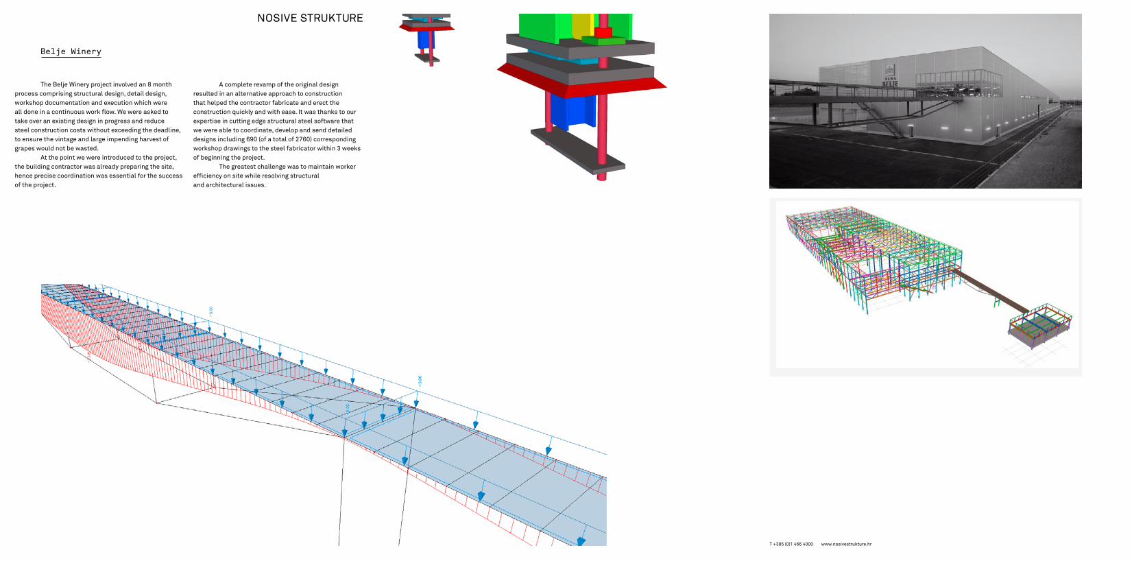
Belje Winery
The Belje Winery project involved an 8 month process comprising structural design, detail design, workshop documentation and execution which wereall done in a continuous work flow. We were asked to take over an existing design in progress and reduce steel construction costs without exceeding the deadline, to ensure the vintage and large impending harvest of grapes would not be wasted.
At the point we were introduced to the project, the building contractor was already preparing the site, hence precise coordination was essential for the success of the project.
A complete revamp of the original design resulted in an alternative approach to construction that helped the contractor fabricate and erect the construction quickly and with ease. It was thanks to our expertise in cutting edge structural steel software that we were able to coordinate, develop and send detailed designs including 690 (of a total of 2760) corresponding workshop drawings to the steel fabricator within 3 weeks of beginning the project.
The greatest challenge was to maintain worker efficiency on site while resolving structural and architectural issues.
T +385 (0)1 466 4000 www.nosivestrukture.hr
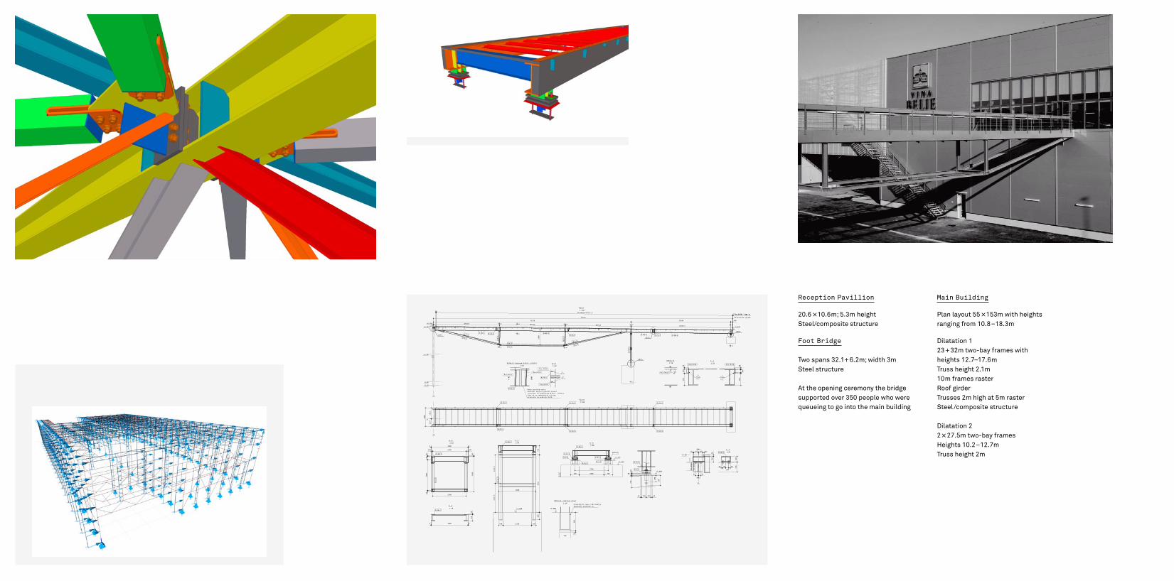
Reception Pavillion
20.6 × 10.6m; 5.3m heightSteel/composite structure Foot Bridge
Two spans 32.1+ 6.2m; width 3mSteel structure
At the opening ceremony the bridge supported over 350 people who werequeueing to go into the main building
Main Building
Plan layout 55 × 153m with heights ranging from 10.8 – 18.3m
Dilatation 123 + 32m two-bay frames withheights 12.7–17.6mTruss height 2.1m10m frames raster Roof girderTrusses 2m high at 5m rasterSteel/composite structure
Dilatation 2 2 × 27.5m two-bay frames Heights 10.2 – 12.7m Truss height 2m
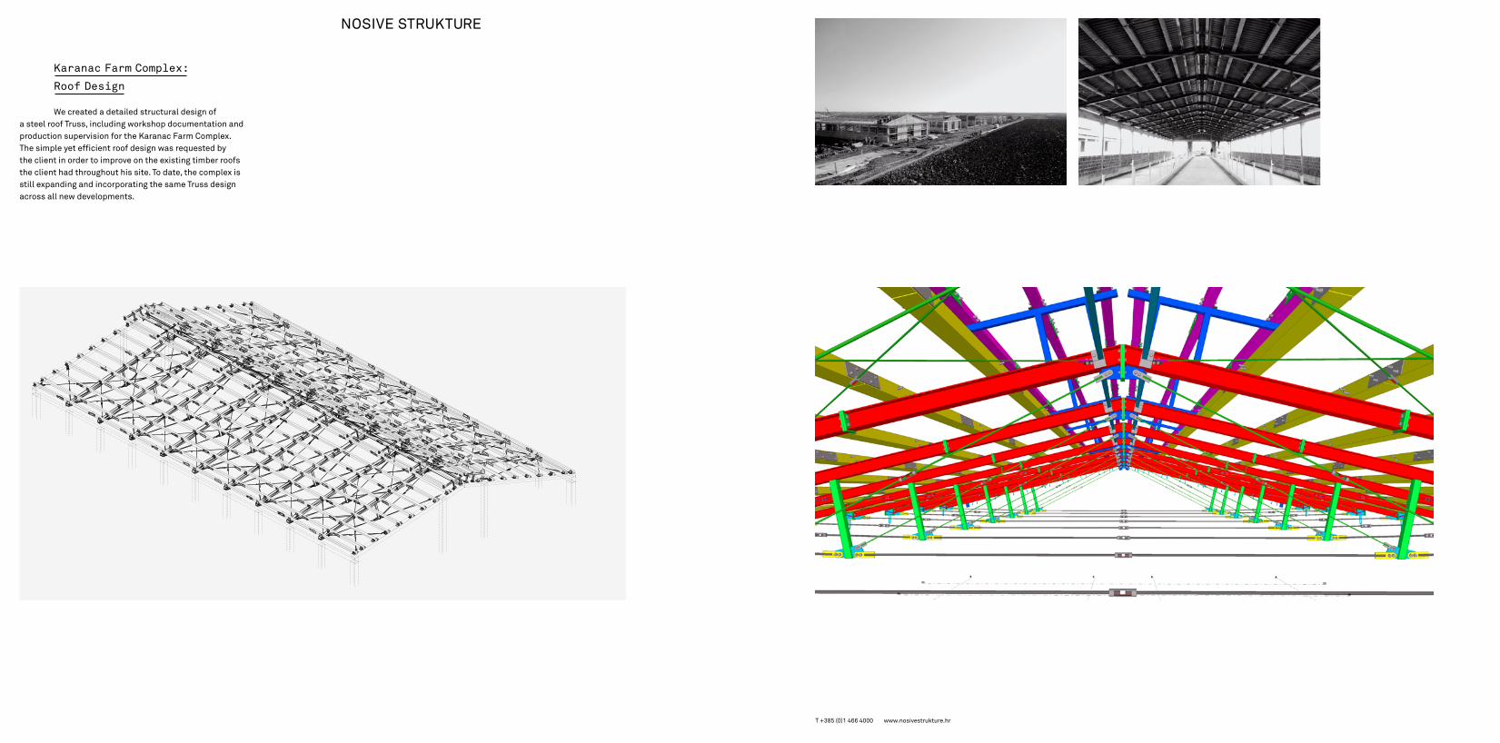
Karanac Farm Complex:
Roof Design
We created a detailed structural design ofa steel roof Truss, including workshop documentation and production supervision for the Karanac Farm Complex. The simple yet efficient roof design was requested by the client in order to improve on the existing timber roofs the client had throughout his site. To date, the complex is still expanding and incorporating the same Truss design across all new developments.
T +385 (0)1 466 4000 www.nosivestrukture.hr

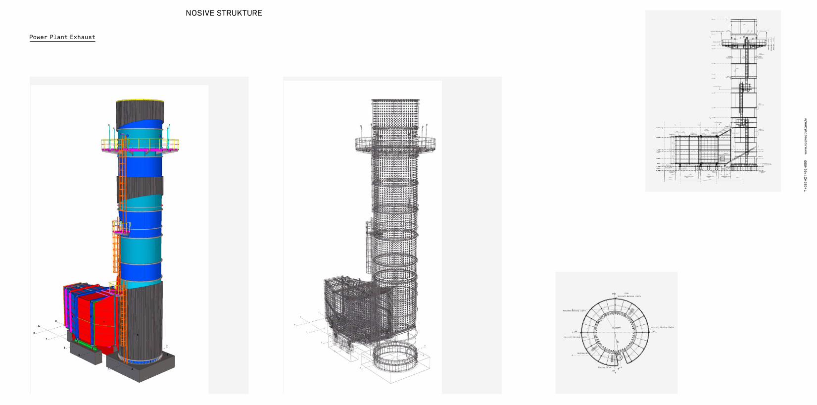
Power Plant Exhaust
T +
385
(0)1
466
400
0 w
ww
.nos
ives
truk
ture
.hr
7
-0.500
0.0000.300
1.00
2.000
3.300
6.300
3.713
8.300
10.300
12.300
15.300
18.300
19.133
21.300
24.300
25.000
27.300
30.300
0.300
6.300
2.000
3.300
6.300
3.7133.713
0.000
2.000
0.300
-0.500
6.300
0.0000.300
2.000
3.713
3.300
1.00
0.000
1.00
-0.500
1.00
3.300
-0.500
1 3 5
D=4794Gas PathGas Path
4998
DETJ
JJ
FlangeL200*100*10
G
16162.514029
2661.1
H
F
E
D
BC
A
DETCInsulation
4200
FlangePL10*150FlangePL10*150
4829
cc
bb
aa
2752
5504
5520
Foundation C20/25
DETFInsulation
3162.5
T.O.C.+0.300
B.O.S.+0.330
2133.5
2133.6
2752
8
Transition piece
DETFInsulation
DETDInsulation
8
FlangePL15*113
DETGInsulation
DETEInsulation
3200
4000 2538.9
30°
Silencer Duct
1736 289
Transition piece
Drainage
Manhole
FlangePL10*150FlangePL10*150
DETEInsulation
DETGInsulation
DETDInsulation
T.O.G.+8.800
FlangePL10*150
FlangeL150*100*10
FlangePL10*150
T.O.G.+16.000
T.O.G.+25.000
100InsideInsulation
InsideInsulation
2
DETHField joint
DETHField jointAircraft Warning Lights
8
B.O.S.+0.340T.O.C.+0.300
Foundation C20/25
Manhole
DETHField joint
DETBInsulation
DETAInsulation
2 100 InsideInsulationInsideInsulation
Monitoring Ports231
1300
Sample Port
Sample Port
1500
EPA Test Port
EPA Test Port
1700
Opacity Port
Opacity Port
132
8
77
A
C
EAircraft Warning Lights
2507
2750
PL2990*8
90°
270°
0°180°
10°
Grating 30 mm
Aircraft Warning Lights
Grating 30 mm
440770
Aircraft Warning Lights
Aircraft Warning Lights
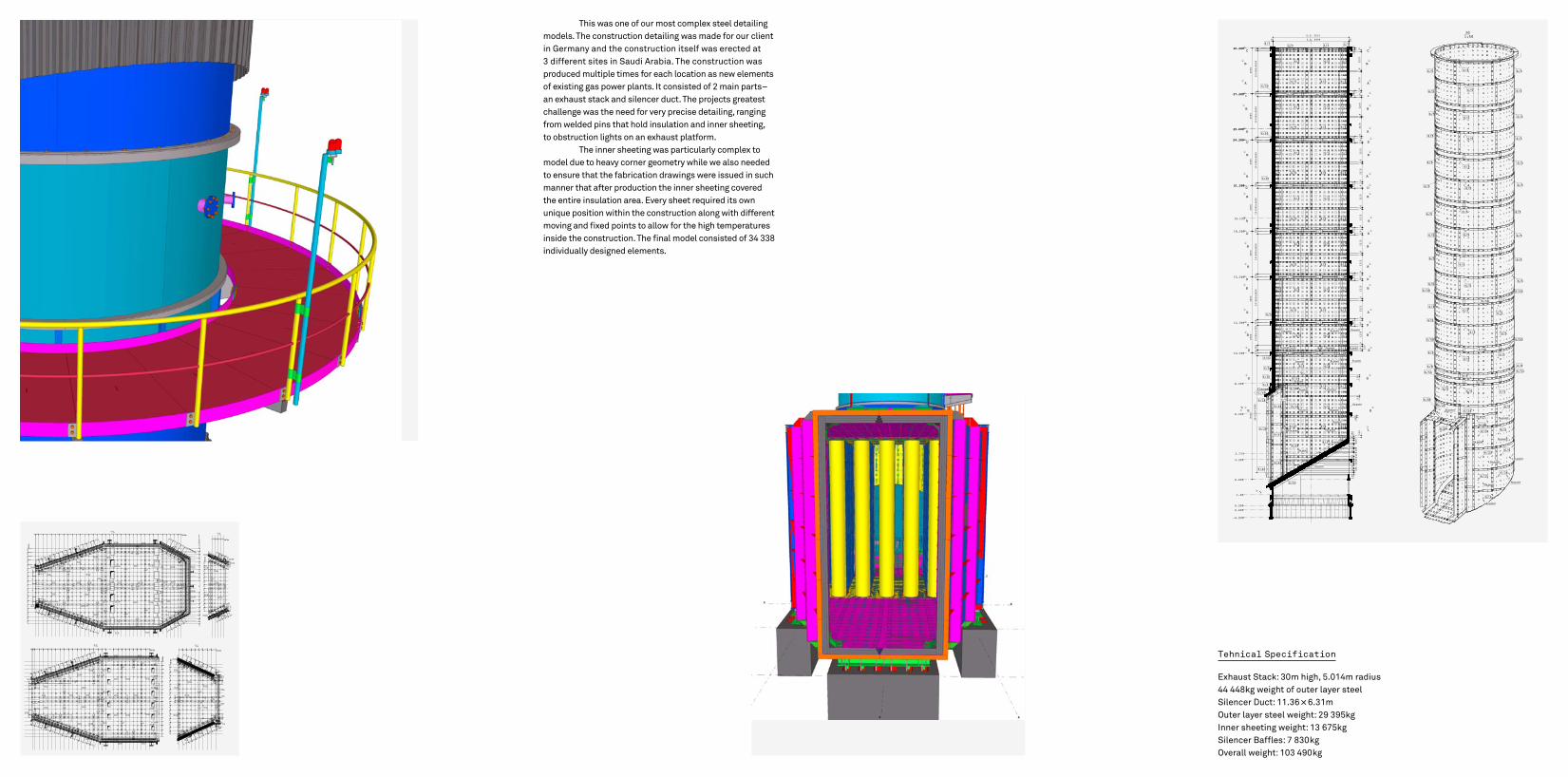
This was one of our most complex steel detailing models. The construction detailing was made for our client in Germany and the construction itself was erected at 3 different sites in Saudi Arabia. The construction was produced multiple times for each location as new elements of existing gas power plants. It consisted of 2 main parts–an exhaust stack and silencer duct. The projects greatest challenge was the need for very precise detailing, ranging from welded pins that hold insulation and inner sheeting,to obstruction lights on an exhaust platform.
The inner sheeting was particularly complex to model due to heavy corner geometry while we also needed to ensure that the fabrication drawings were issued in such manner that after production the inner sheeting coveredthe entire insulation area. Every sheet required its ownunique position within the construction along with different moving and fixed points to allow for the high temperatures inside the construction. The final model consisted of 34 338 individually designed elements.
Tehnical Specification
Exhaust Stack: 30m high, 5.014m radius44 448kg weight of outer layer steelSilencer Duct: 11.36 × 6.31mOuter layer steel weight: 29 395kgInner sheeting weight: 13 675kgSilencer Baffles: 7 830kgOverall weight: 103 490kg
6/21
6/31
6/3
6/34
6/5
6/5
3d1:50
6/506/50
6/5
6/56/5
6/5
6/56/5
6/5
6/56/56/5
6/5
6/85
6/84
6/31
6/50
6/50
6/506/50
6/51
6/51
6/8
6/8
6/24
6/30
6/51
6/8
6/25
6/56/5
6/56/5
6/5
6/56/56/5
6/56/5
6/5
6/56/56/5
6/56/56/5
6/56/56/5
6/56/56/5
6/56/56/5
6/56/56/5
6/56/56/5
7
3.300
2.000
-0.500
0.3000.000
1.00
6.300
8.300
12.300
3.713
10.300
21.300
19.133
18.300
15.300
21.300
30.300
24.300
25.000
24.300
30.300
27.300
25.000
27.300
Axis C-C (Front View)1:50
AA 1215
3000
10*2
65=2
650
6/50
I
I
8300
29*2
65=7
685
110
155
110
235
110
139
1856/40
6/46/48
6/43
L
L
DD
BB
EE
GG
HH
6/5 6/56/1FlangePL/48
6/39
6/29
6/38
6/466/22
6/47
6/29
6/41
6/48
6/28
2000
350
5*26
5=13
2532
035
5
6/8
6/51
6/5
6/8
6/25 6/24
6/5
6/51
6/50
6/5 6/5
110
110
6518
580
155
115
200
6520
0
265
6/37
6/5 6/5
6/56/5
150
110
225
110
110
6/516/86/8
6/5
6/5
6/50
6/51
6/5
6/50
6/5
110
1215
110
110
460
1215
3000
10*2
65=2
650
AA
DD
DD
DD
AA
AA
BB
BB
BB
1215
3000
3000
10*2
65=2
650
350
6/506/50
6/5
6/5
6/5
6/5
6/5
6/5
6/5
6/5
350
10*2
65=2
650
350
6/50
6/50
6/5
6/50
6/5
6/50
6/5
6/5
6/5
6/5
460
6/5
6/5
6/50
6/5
6/5
6/50
6/5
6/5
6/5
6/5
110
1215
110
110
1215
110
1215
6/5
6/50
6/5
6/5
6/50
6/5
6/50
6/50
6/5
6/5
11011
012
1511
0
460
110460 11
0
DD
BB
BB
BB
AA
AA
CC
DD
O.D. 5014
460
I.D. 4998
110
3000
3000
350
6/50
6/50 6/506/50
350
10*2
65=2
650
6/50
6/50
6/5 6/5
6/5
6/5
6/5
6/5
10*2
65=2
650
120 57
6/7
6/5 6/5
6/5 6/5
8
6/7
1215
6/5
6/5
6/5
6/506/50
6/5
6/5
6/5
110
110
1215
110460
110
1215
110
6/7
1215
1215
110
6/5
6/56/5
6/5
6/7
1102
120
8
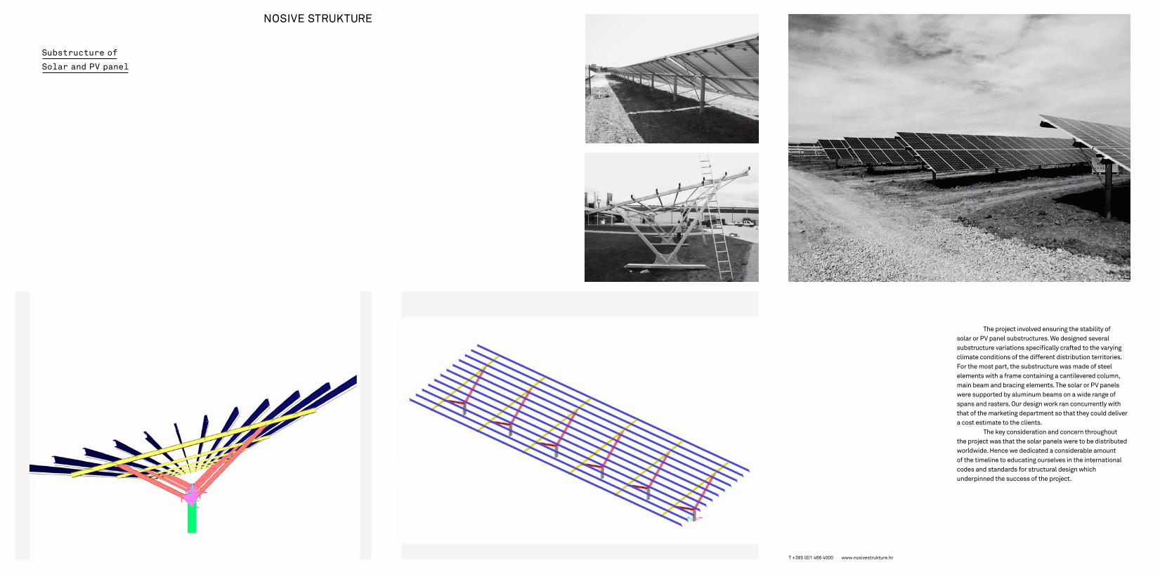
Substructure of
Solar and PV panel
T +385 (0)1 466 4000 www.nosivestrukture.hr
The project involved ensuring the stability of solar or PV panel substructures. We designed several substructure variations specifically crafted to the varying climate conditions of the different distribution territories. For the most part, the substructure was made of steel elements with a frame containing a cantilevered column, main beam and bracing elements. The solar or PV panels were supported by aluminum beams on a wide range of spans and rasters. Our design work ran concurrently with that of the marketing department so that they could deliver a cost estimate to the clients.
The key consideration and concern throughout the project was that the solar panels were to be distributed worldwide. Hence we dedicated a considerable amount of the timeline to educating ourselves in the international codes and standards for structural design which underpinned the success of the project.

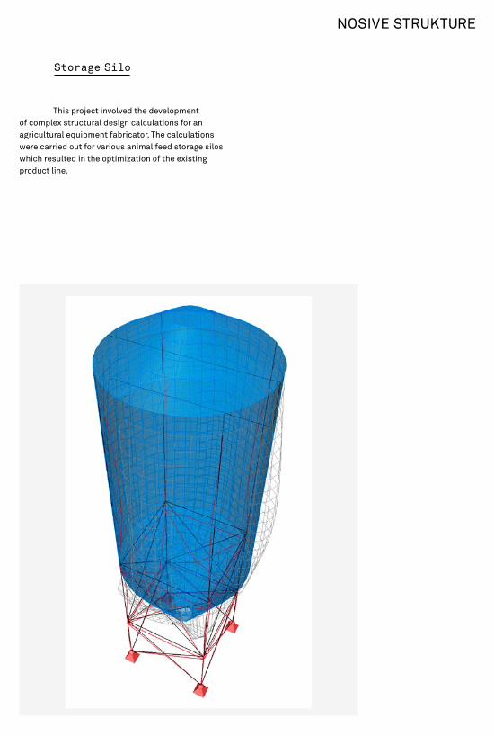
This project involved the development of complex structural design calculations for an agricultural equipment fabricator. The calculations were carried out for various animal feed storage silos which resulted in the optimization of the existing product line.
Storage Silo

T +
385
(0)1
466
400
0 w
ww
.nos
ives
truk
ture
.hr
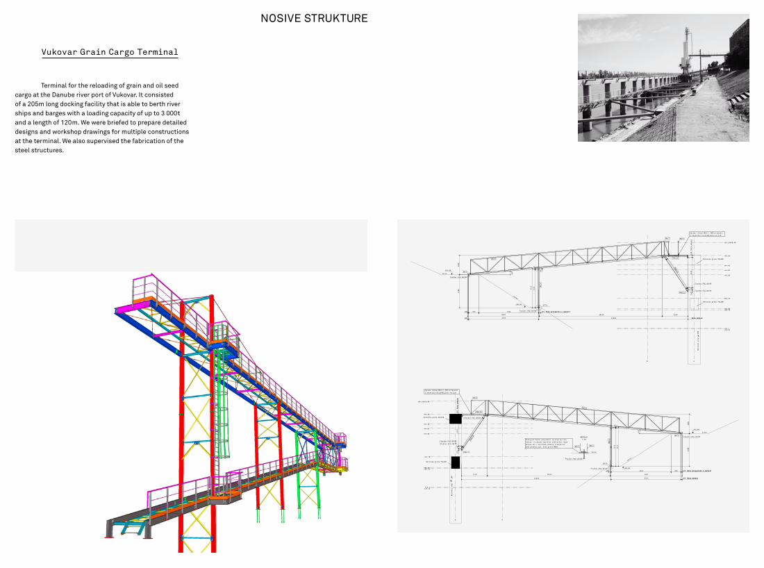
Terminal for the reloading of grain and oil seed cargo at the Danube river port of Vukovar. It consisted of a 205m long docking facility that is able to berth river ships and barges with a loading capacity of up to 3 000t and a length of 120m. We were briefed to prepare detailed designs and workshop drawings for multiple constructions at the terminal. We also supervised the fabrication of the steel structures.
Vukovar Grain Cargo Terminal
AB
+86.240=0.00
+85.20
+84.40
+84.02
+83.60
+81.70
+80.80+80.70
+79.2+79.15
1600
12292 Kota ankeraKota ankera
10115
MN/2
2700
100 5737
3215
3133
5.3°
5897
100 816 4921
MN/4
teren
+83.60MN/6
Fischer FAZ 20/60
DET B
teren
+80.90
180 Kotu provjeriti u naravi!Kotu provjeriti u naravi!Fischer FAZ 20/60
94
82
2476
2118
Fischer FAZ 20/60
PMN/10
MN/7 MN/8
Betonska greda 70x100
Betonski stup
100
152
198
PMN/12Fischer FAZ 20/60
Betonska greda 80x100
Ogradu (sklop MN/8 i MN7)pripasatii zavaritin na gradilištu na lim
180
Kota ankera
PMN/11
A B
+86.240=0.00
+85.20
+84.40
+84.02
+83.60
+81.70
+80.80+80.70
+79.2+79.15
1600
10115
12292
MN/2
198
2476
2118
PMN/11
PMN/12
Fischer FAZ 20/60
Fischer FAZ 20/60
PMN/10
Fischer FAZ 20/60
MN/8
152
Betonski stup
100
Betonska greda 70x100
180
Kota ankera
Kota ankera
Ogradu (sklop MN/8 i MN7)pripasatii zavaritin na gradilištu na lim
Betonska greda 80x100
4921 816 100 Kotu provjeriti u naravi!Kotu provjeriti u naravi!
27003215
3133
5897
5737 100 Kota ankeraKota ankera
5.3°
180
+80.90
teren
Fischer FAZ 20/60
DET B
82
MN/4
+83.60
teren
Fischer FAZ 20/60MN/6
teren
Postojeci beton pripremiti za stup na licu mjesta. U slucaju kolizije odstraniti višakbetona ili u sprotnom podliti s masom zapodlijevanje npr. Sika grout MB30
Fischer FAZ 20/60
MN/5 MN/4
DETAIL B
1:10
T +385 (0)1 466 4000 www.nosivestrukture.hr
Technical Specification
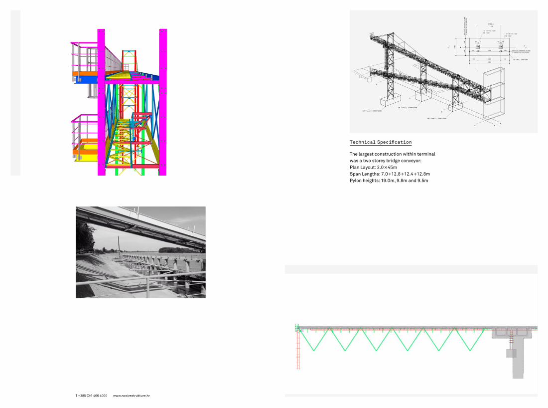
The largest construction within terminalwas a two storey bridge conveyor:Plan Layout: 2.0 × 45m Span Lengths: 7.0 + 12.8 + 12.4 + 12.8m Pylon heights: 19.0m, 9.8m and 9.5m

Wastewater
Treatment Plant
T +385 (0)1 466 4000 www.nosivestrukture.hr
Our work involved the structural analysis, framework and reinforcement drawings for the circular center-feed clarifier with a scraper sludge removal system as well as all related auxiliary facilities. The tank has a capacity of approximately 3 217m3. The clarifier consists of the tank which has a diameter of 32m. The tank wall is 4m high with a uniform thickness of 0.4m. The base slab is 0.4m thick, with 6.6% slope towards the center. The sludge drain channel is positioned at the top of the tank wall. The channel consists of a 0.2m thick wall and a base slab that is 0.3m thick.
Top LayerBottom Layer
CL
142
102
60
56
60 Radius 7.35 m
Radius 1.54 m
Radius 8.02 m
60 Radius 7.35 m Radius 7.35 m
Radius 8.02 m
RAFT PLATECIRCULAR REINFORCEMENT
Radiu
s 8.02
m
Radius 7.31 m
3010030010030
660
302004012708050080127040
2303280
Section D-DScale 1:50
3,0
1,5
190 120 190
50
350
89
274
30
100
560
893
50
350
167
30
50
246
50 30 250 48 202 30 50
3130
105
275
+451,36
+445,07
+445,57
+449,07
+449,96+450,20
+450,74
+451,54
+453,00
+453,50
+454,00 +454,00
3130
330
50
115
159
30
100
1310 40 4015 60 350 60 1540 40 1310
280 280
SLOPE SLOPE
2
1
1
66
7
BLINDING CONCRETE
5
453.10
Detail No. 1
453,10
454,00
+453,00
453,50453.50453,50
SCUM CHAMBER
SCUM BOX
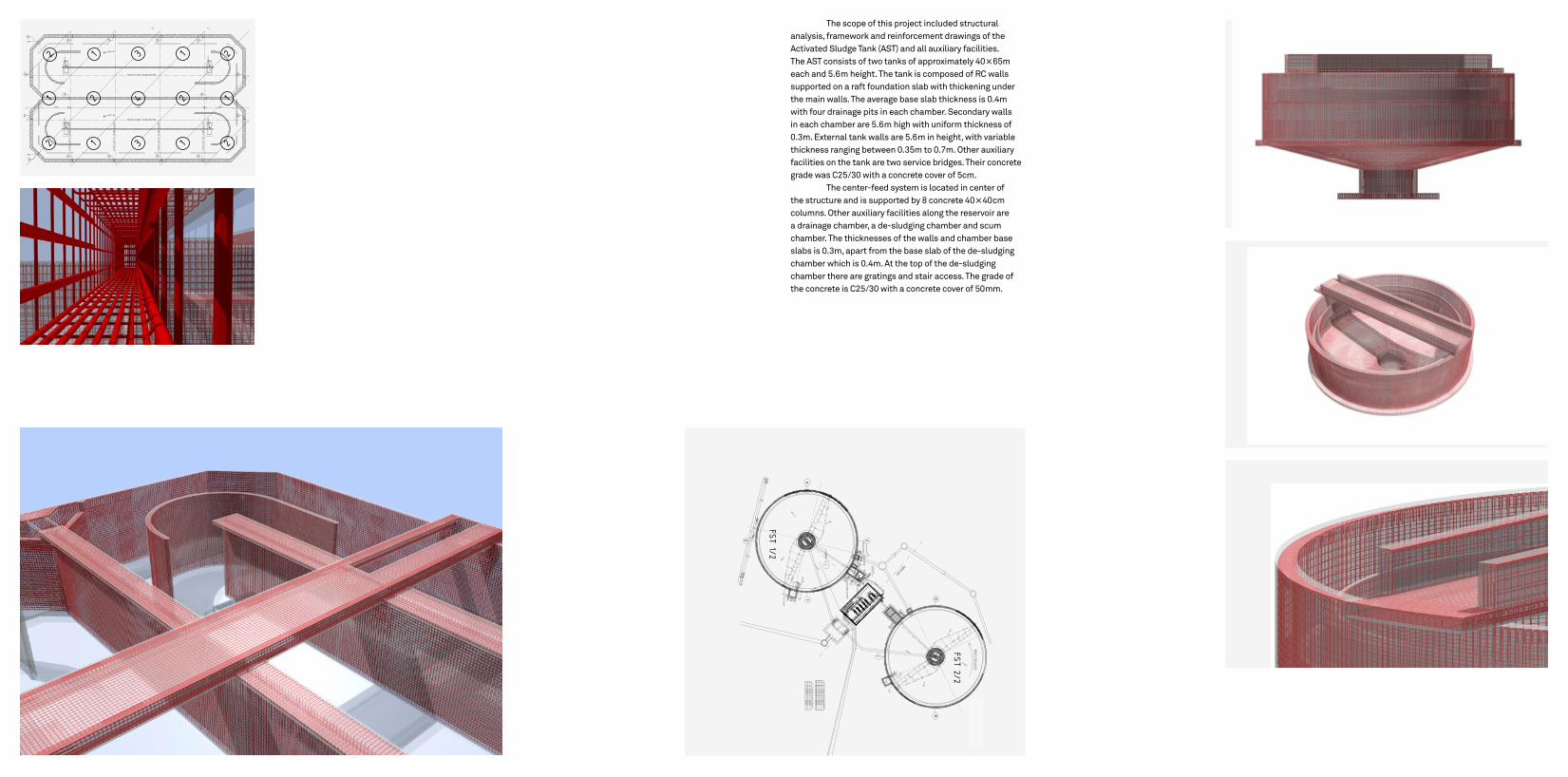
The scope of this project included structural analysis, framework and reinforcement drawings of the Activated Sludge Tank (AST) and all auxiliary facilities. The AST consists of two tanks of approximately 40 × 65m each and 5.6m height. The tank is composed of RC walls supported on a raft foundation slab with thickening under the main walls. The average base slab thickness is 0.4m with four drainage pits in each chamber. Secondary walls in each chamber are 5.6m high with uniform thickness of 0.3m. External tank walls are 5.6m in height, with variable thickness ranging between 0.35m to 0.7m. Other auxiliary facilities on the tank are two service bridges. Their concrete grade was C25/30 with a concrete cover of 5cm.
The center-feed system is located in center of the structure and is supported by 8 concrete 40 × 40cm columns. Other auxiliary facilities along the reservoir are a drainage chamber, a de-sludging chamber and scum chamber. The thicknesses of the walls and chamber base slabs is 0.3m, apart from the base slab of the de-sludging chamber which is 0.4m. At the top of the de-sludging chamber there are gratings and stair access. The grade of the concrete is C25/30 with a concrete cover of 50mm.
21
Construction stage border
Construction stage border
Construction stage border
Construction stage border
Construction stage border
Construction stage border
12222
2
2
22221
2 2
2
2 +452.93
+452.93
+452.13
+452.13
+452.13
+452.13
461 789 50 3901 50 789 461

Zürich Stadium
T +385 (0)1 466 4000 www.nosivestrukture.hr
This design for a stadium in Zürich with a capacity for 20 000 people, will become home to two football clubs if it is successful in passing through to development. For this stage of the project we were required to provide a cost estimate focussing on the steel and concrete structures. The stadium roof is made from cantilever trusses with a 24m span on 21.2m raster. The trusses are supported with large vertical oriented trusses called “Mega-Columns” that are 23m in height. The total weight of all the steel structures was 1 100 000kg. In order to get an accurate cost estimate of the precast Raker beams we made a 3D model in Allplan to ascertain the number of different types of beams. We then built a 3D model to find out the total reinforcement weight for each type of beam.
±0.00
+0.91
+6.95
Treppenelem ent
S.TG. -2
S4
OrtbetonDecke
Balken 60x60cm
1S1S
S.TG. -9
Detail A
Detail B
±0.00
+6.48
+13.37
Detail C1
1915 7985 60 675 60 150 255
548
6040
5865
25100
25 45 60
±0.00
+6.48
+14.24
±0.00
+0.91
+6.95
S2
Balken 60x60cm
OrtbetonDecke
S.TG. -9Treppenelement
S.TG. -4
3S3S
Detail A
Detail B
Detail C
1915 792 60 971 60 316 85
548
6040
671
251002
5
385 60
±0.00
+6.48
+13.37
±0.00
+6.925+7.46
S4
OrtbetonDecke
S3 S3
S.TG. -5
Balken 60x60cm
OrtbetonWand
Ortbeton
Detail B1
Detail C1
232 60 675 60 150 255
548
6040
5865
25100
±0.00
+0.91
+6.95
S.TG. -1
OrtbetonDecke
S.TG. -9Treppenelem ent
S2
Balken 60x60cm
S1S1
Detail A
Detail B
±0.00
+6.48
+14.24
Detail C
1915 7985 60 675 60 320 85
548
6040
6735
251002
5
25 45 60