nrm plan on-stream dams dams what is a low flow ... at flows above the threshold flow rate the...
TRANSCRIPT
CONTACT
Main Office
Northern and Yorke NRM Board
PO Box 175
41-49 Eyre Road
Crystal Brook SA 5523
Ph: (08) 8636 2361
Fx: (08) 8636 2371
www.nynrm.sa.gov.au
June 2011
NRM Plan
Government of South Australia
Northern and Yorke NaturalResources Management Board
This fact sheet was produced with the support of the Australian Government’s Caring for Our Country program.
On-stream Dams
What is a Low Flow Bypass?A low flow by-pass is a device used to prevent a water storage, dam or other form of diversion from harvesting low flows (sometimes called environmental flows). These low flows are critical in maintaining our sensitive water dependant ecosystems.
Threshold Flow RateThis is the rate of water flow which must be exceeded before water can be harvested or collected. It is normally measured in litres per second (l/s) and the required rate will be specified in your Water Affecting Activities Permit.
When does this Factsheet Apply?Watercourses and dams or diversions have many forms. Three fact sheets have been prepared to cover most situations. These are:1. On-stream dams (1 to 70 l/s)2. Off-stream dams (10 to 520 l/s)3. Off-stream dams with 50:50 flow split
(5 to 2000 l/s)
It is not anticipated that these fact sheets will be appropriate for all dams. Some dams will require a special design to suit the local conditions. This fact sheet applies to on-stream dams with a flow threshold of between 1 and 70 l/s.
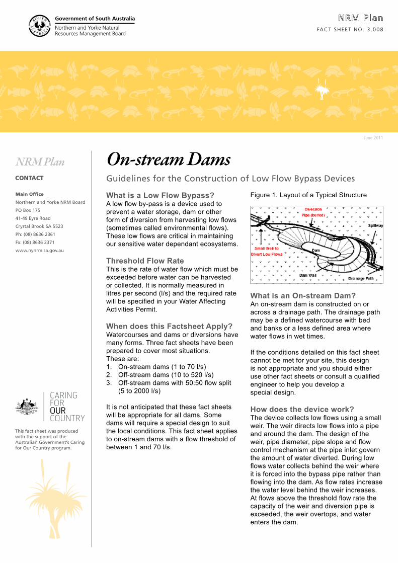
What is an On-stream Dam?An on-stream dam is constructed on or across a drainage path. The drainage path may be a defined watercourse with bed and banks or a less defined area where water flows in wet times.
If the conditions detailed on this fact sheet cannot be met for your site, this design is not appropriate and you should either use other fact sheets or consult a qualified engineer to help you develop a special design.
How does the device work?The device collects low flows using a small weir. The weir directs low flows into a pipe and around the dam. The design of the weir, pipe diameter, pipe slope and flow control mechanism at the pipe inlet govern the amount of water diverted. During low flows water collects behind the weir where it is forced into the bypass pipe rather than flowing into the dam. As flow rates increase the water level behind the weir increases. At flows above the threshold flow rate the capacity of the weir and diversion pipe is exceeded, the weir overtops, and water enters the dam.
FACT SHEET NO. 3 .008
Guidelines for the Construction of Low Flow Bypass Devices
Figure 1. Layout of a Typical Structure
Government of South Australia
Northern and Yorke NaturalResources Management Board
Government of South Australia
Northern and Yorke NaturalResources Management Board
Government of South Australia
Northern and Yorke NaturalResources Management Board
Government of South Australia
Northern and Yorke NaturalResources Management Board
Design and ConstructionThese devices are formed using simple materials and can be designed and constructed by skilled handy-people or civil works contractors. A survey (dum py) level and experienced user are required. Take care to follow the instructions closely. The guidelines have been developed to ensure the structure carries the correct flow and will be unlikely to block with sediment.
Functional Details IntroductionThis design uses two weirs to control flows; an in-stream weir and a diversion weir. Guidance on determining the appropriate weir dimensions and levels is provided here. Structural design information is provided later in this fact sheet.
This type of low flow bypass device requires a watercourse with defined channel and flat floodplain on which a dam can be dug.
Pipe Inlet Flow Control Mechanism Flow into the pipe is governed by an inlet flow control mechanism known as an orifice. An orifice is simply a round hole cut into the centre of an end cap placed on the inlet of the pipe.
The flow through the orifice is closely related to the orifice diameter. This orifice provides accurate flow control. Use Figure 5 or 6 to determine your required orifice diameter, based on your required threshold flow rate.
Pipe DiameterWe recommend that you use Polypropylene (poly) pipe for the flow bypass device. Poly pipe is available in a number of standard diameters. Select pipe with an ‘internal’ diameter at least 1.5 times larger than your required orifice diameter.
Note that pipes are usually referred to according to their ‘nominal’ diameter. This is usually slightly larger than the ‘internal’ diameter. Check the availability of pipe diameters with your local supplier and ask for the ‘internal’ diameter.You will also need to purchase an end cap for the pipe, in which to drill or cut the orifice.
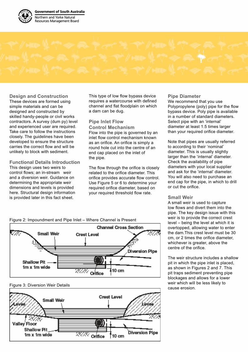
Small WeirA small weir is used to capture low flows and divert them into the pipe. The key design issue with this weir is to provide the correct crest level – being the level at which it is overtopped, allowing water to enter the dam.This crest level must be 30 cm, or 2 times the orifice diameter, whichever is greater, above the centre of the orifice.
The weir structure includes a shallow pit in which the pipe inlet is placed, as shown in Figures 2 and 7. This pit traps sediment preventing pipe blockages and allows for a lower weir which will be less likely to cause erosion.
Figure 2: Impoundment and Pipe Inlet – Where Channel is Present
Figure 3: Diversion Weir Details

Government of South Australia
Northern and Yorke NaturalResources Management Board
Government of South Australia
Northern and Yorke NaturalResources Management Board
Government of South Australia
Northern and Yorke NaturalResources Management Board
Government of South Australia
Northern and Yorke NaturalResources Management Board
Example:For a threshold flow rate of 15 l/s, the orifice diameter is 115 mm. Minimum pipe diameter (internal diameter) is 173 mm.
Example:For a threshold flow rate of 60 l/s, the orifice diameter is 210 mm. Minimum pipe diameter (internal diameter) is 315 mm.
Pipe SlopePipe slope is of critical importance to the functioning of the device. Incorrect slope will result in incorrect threshold flow rate and increased likelihood of sediment blocking the pipe. When laying the pipe it is important to get the slope as even as possible. Undulations should be avoided. Having said that, the best laid pipe will still have minor variations in slope along its length. It is the slope of the flattest section which is of most importance.
This minimum slope must be above a certain value, which is dependant on the pipe diameter. Use Table 1 to select your minimum pipe slope based on your ‘internal’ pipe diameter.
Figure 4. Orifice Diameter versus Threshold Flow Rate (1 – 20 l/s)

Government of South Australia
Northern and Yorke NaturalResources Management Board
Government of South Australia
Northern and Yorke NaturalResources Management Board
Government of South Australia
Northern and Yorke NaturalResources Management Board
Government of South Australia
Northern and Yorke NaturalResources Management Board
Example:For a pipe diameter of 300 mm the pipe must be installed at a slope steeper than 0.4%, or 40 cm fall in 100 m.
InternalPipe Diameter
Minimum Pipe Slope% m per 100 m
47 mm 4 % 4 m per 100 m60 mm 3 % 3 m per 100 m71 mm 2 % 2 m per 100 m86 mm 2 % 2 m per 100 m
105 mm 2 % 2 m per 100 m119 mm 1 % 1 m per 100 m133 mm 1 % 1 m per 100 m152 mm 1 % 1 m per 100 m171 mm 1 % 1 m per 100 m190 mm 0.5 % 0.5 m per 100 m214 mm 0.5 % 0.5 m per 100 m238 mm 0.5 % 0.5 m per 100 m267 mm 0.5 % 0.5 m per 100 m
300 mm or greater 0.4 % 0.4 m per 100 m
Design Dimension Figures and Tables
Note that ‘internal’ pipe diameters vary slightly between pipe manufacturers and pipe structural grades. The table has been prepared based on ‘internal’ pipe diameters from one manufacturer. Select the ‘internal’ pipe diameter from the table which is closest to yours.
Figure 6: Profile of Device showing Pipe Slopes
Structural Design and Construction
IntroductionStructurally speaking this type of low flow bypass is relatively simple and many aspects of the device can be designed and constructed according to local conditions and available materials. The key functional requirements have been outlined in earlier pages. This section gives guidance to assist with some other aspects of design and information to help with installation.
Pipe SlopePipe slope is of critical importance to the functioning of the device. Incorrect pipe slope will result in incorrect threshold flow rate and increased likelihood of the pipe blocking with sediment. No section of pipe can have a slope less than the minimum slope, as determined earlier using Table 1.

Government of South Australia
Northern and Yorke NaturalResources Management Board
Government of South Australia
Northern and Yorke NaturalResources Management Board
Government of South Australia
Northern and Yorke NaturalResources Management Board
Government of South Australia
Northern and Yorke NaturalResources Management Board
When installed on existing dams, to meet this requirement the pipe inlet and small weir will need to be located some distance upstream of the dam. From this point the pipe should be laid at an even grade around the dam to the dam wall. The pipe should pass over the dam wall on top of the existing overflow spillway. See Figure 1 on Page 1.
Before constructing the bypass, check the slopes using a survey (dumpy) level and tape measure. For a pipe laid at an even grade from its inlet to the dam spillway the slope is determined using the following equation:
Height of Pipe Inlet above Dam Spillway (m) Slope (%) = _____________x 100% Length of Pipe from Inlet to Dam Spillway (m)
Don’t forget to allow for bends or curvature in the pipe when measuring the length of pipe. If the pipe is laid unevenly, the calculated slope will be the average slope. Some sections will be flatter, and these must be steeper than the minimum slope.
To increase the pipe slope, shift the pipe inlet further upstream from the dam. See Figure 6 on the previous page. Wherever possible, lay the pipe at a gradient steeper than the minimum slope. The survey (dumpy) level can also be used to mark the route of the pipe on the ground so that its at an even slope.
In some very flat locations it may not be possible to achieve the minimum pipe slope. In these locations a special design will be required and you should consult a qualified engineer. For new dams the pipe may be laid through the dam and through the dam wall. Adequate seepage collars will be required to prevent piping failure of the dam wall.
Small WeirThe small weir can be constructed from a variety of materials such as concrete and timber.The weir must be water tight (a strong, long life, UV resistant commercial grade plastic liner may assist) and provide the required crest level, as directed by guidance on previous pages.
Where the dam is located on a watercourse where there is no defined channel, levees may need to be constructed across the valley to direct flows into the weir and pipe inlet. See Figures 3 and 7. These should extend across the drainage path ending at higher ground on either side of the valley, but should not increase the catchment area of the dam.
The height of the levees should be determined based on local conditions. They should over top in high flows so that flows are not overly concentrated, causing erosion. A minimum height of 10 cm above the weir level is recommended. Compact well, sow grass on the finished levees and fence to prevent grazing and erosion of the levees.
Shallow PitPlace rock in the creek bed The shallow pit is used to collect sediment and prevent it entering the pipe. It also allows a lower weir crest level whilst still achieving the required height above the bottom of the orifice. A lower weir will be less likely to cause erosion associated with water cascading over the weir.The pit should be installed in the lowest point of the drainage path.
The shallow pit may be formed with concrete, timber or bricks. It should be rectangular with a hard base (approximately 1 m x 1 m wide) and hard sides. It can immediately abut the weir or be set back slightly.The base level should be 10 cm below the bottom of the diversion pipe.
Figures 1 and 7 show the layout and recommended dimensions of the pit.

Government of South Australia
Northern and Yorke NaturalResources Management Board
Government of South Australia
Northern and Yorke NaturalResources Management Board
Government of South Australia
Northern and Yorke NaturalResources Management Board
Government of South Australia
Northern and Yorke NaturalResources Management Board
Other Design and Maintenance Issues
Erosion Control Water cascading over the small weir is likely to lead to erosion on the downstream side of the weir. To prevent this, the bed of the watercourse channel or drainage path must be protected with rock for a length of 5 times the weir height. Rock protection must also extend up the banks to the height of the weir.
Excavate the area to be rock protected to a depth of 30 cm and then fill this area with rock. Rock must have a range of sizes, with the average being about 200 mm in diameter. Some rock should be up to 300 mm in diameter and small rock/gravel should also be used to fill the gaps between bigger rocks. Rock must be hard and angular, not soft or rounded. Rock must be set into the creek bed rather than place upon it. Rock must be placed in such a way as to contain flows.
The finished level of the rock must therefore be lower in the centre of the drainage path than at the edges. Encourage grass to grow over the rock by filling gaps in the rock with soil and casting seed over the finished area.
Bury the PipeStandard grade poly pipe laid directly on the ground will be prone to crushing or damage by stock. If stock access the area the pipe must be buried.
Figure 7: Layout of Small Weir, Shallow Pit, Levees and Pipe Inlet Erosion Control at Pipe OutletWater gushing out of the pipe outlet may also lead to localised erosion. It should be angled downstream and not directed at the banks. Ensure the pipe is held in place and unable to move about. One way to do this is to drive steel droppers either side of it and tie it to the droppers with strong wire.
Where the dam spillway is stable and erosion resistant, the pipe outlet may be placed on the spillway. Otherwise the pipe outlet should be placed within the watercourse or drainage path, below the dam, at bed level. An energy dissipater must be constructed to prevent water gushing out of the pipe causing erosion.
To make an energy dissipater construct a pit, similar to the inlet pit, in the base of the watercourse and place the pipe outlet in the pit. The pit should be at least 3 times as deep as the pipe diameter, or a minimum of 30 cm deep. It should be square with sides at least 5 times as long as the pipe diameter, or a minimum 1 m long. The pit may be formed with concrete, timber or bricks, but must be strong with no gaps in the walls or base.
The pipe should pass through the upstream wall of the pit at base level. The pipe should be angled directly at the downstream wall of the pit. The end of the pipe should be at least 4 times the pipe diameter from the downstream wall of the pit.

Government of South Australia
Northern and Yorke NaturalResources Management Board
Government of South Australia
Northern and Yorke NaturalResources Management Board
Government of South Australia
Northern and Yorke NaturalResources Management Board
Government of South Australia
Northern and Yorke NaturalResources Management Board
MaintenanceThe operation of the low flow bypass should be monitored and any issues addressed as they arise. Most importantly the device should be observed in operation during the first few flow events after installation and regularly thereafter.
Attention should be paid to the following potential issues:• Blockage of the pipe inlet
with debris• Blockage of the pipe with debris
or silt• Sediment accumulation in the
shallow pit• Leakage through the weir• Erosion downstream of the weir• Erosion at the pipe outlet
Blockage of the pipe inlet orifice with debris (leaves, grass, sticks etc) may be an ongoing problem in watercourses with a high debris load. The restriction provided by the orifice should prevent the pipe blocking with debris. To reduce inlet blockage with debris, place a fence of wire netting (eg chicken wire) across the watercourse upstream of the shallow pit to trap debris. The netting should only be high enough to be effective in low flows, being overtopped in high flows.
The fence will require cleaning on a regular, but less frequent basis. Sediment should be removed from the pit regularly to prevent it entering the pipe. This design has been prepared to minimise the likelihood of the pipe blocking with sediment. In the unlikely event that it does block it may be cleaned using commercial sewer cleaning equipment. Contact a contractor.
Further InformationWe thank the SAMDB NRM Board and the AMLR Board for their assistance with the development of this fact sheet
Other N&Y NRM FactsheetsDams Off Stream Diversions Off-stream Diversion with 50:50 flow splitWater Affecting Activites and Best Practice Operating ProceduresWater Affecting Activtities Obligations under NRM Act
Help and AssistanceNRM Authorised OfficersSnowtown – 8865 2166Riverton – 8847 2544Minlaton – 8853 2795Port Augusta – 8641 1513, Peterborough – 8651 3577Orroroo – 8658 1086