nrl memoradum report 680 ad-a233 387
TRANSCRIPT

ival Research Laboratoryihington. DC 20375-5000
NRL Memoradum Report 680
AD-A233 387
Theory of Electron Beam TrackingIn Reduced-Density Channels
R. F. FERNsLER, S. P. SLINKER AND P F. HUBBARD
Beam Physics BranchPlasma Physics Division
T
April 2, 19911
Approved for public release; distribution unl,~l J

Form ApprovedREPORT DOCUMENTATION PAGE OMB No. 0704.0188
Public reporting burden for this COllection Of informaion -$ estimated to a erage Ii( hour Per reis orse. including the time for reviewing instructions. searching eiisting data sources.gathering and mintaining the data needed. and completing .44 rewming the Collection Of information Send comments regarding this burden estimate or any other aspect Of thiscohlectin of inf~rmatiotncluding suggestiOs tor red~ucing9 tils burden. to Washington Headquarters Services. Directorate for information Operations and Reports. 1215 JeffersonDavis ighway. Suite 1204. Arlington. VA 22202-4302. and to the Office of Management and Budget. Paperwork Reduction Project (0704-0188). Washington. DC 20503
1. AGENCY USE ONLY (Leave blank) 2. REPORT DATE 3. REPORT TYPE AND DATES COVERED
- 1991 April 2 Interim4. TITLE AND SUBTITLE S. FUNDING NUMBERS
Theory of Electron Beam Tracking in Reduced-Density Channels JO#47-0900-0-1
6. AUTHOR(S)
R. F. Fernsler, S. P. Slinker, and R. F. Hubbard
7. PERFORMING ORGANIZATION NAME(S) AND ADDRESS(ES) B. PERFORMING ORGANIZATIONR;PORT NUMBER
Naval Research LaboratoryWashington, DC 20375-5000 NRL Memorandum
Report 6806
9. SPONSORING / MONITORING AGENCY NAME(S) AND ADDRESS(ES) 10. SPONSORING / MONITORING
AGENCY REPORT NUMBER
DARPA NSWCArlington, VA 22209 Silver Spring, MD 20903-5000
11. SUPPLEMENTARY NOTES
12a. DISTRIBUTION /AVAILABILITY STATEMENT 12b. DISTRIBUTION CODE
Approved for public release; distribution unlimited.
13. ABSTRACT (Maximum 200 words)A theory is presented for the guiding of relativistic electron beams by rarefied
gaseous channels. The analysis is based on analytic computations of the transverseforce felt by a rigid-rod beam propagating off-axis from a channel or reduced gasdensity. The density gradients produce an attractive channel force that can besurprisingly robust, even though it develops from relatively subtle gas chemistryproperties. Static numerical calculations support the analytic work. Longitudinalbeam coupling and effects that degrade channel guidance are discussed as well.
14. SUBJECT TERMS 15. NUMBER OF PAGES
Relativistic electron beam Hose instability 52
Tracking Reduced Gas Density 16. PRICE CODE
Longitudinal coupling_17. SECURITY CLASSIFICATION 18. SECURITY CLASSIFICATION 19. SECURITY CLASSIFICATION 20. LIMITATION OF ABSTRACT
OF REPORT OF THIS PAGE OF ABSTRACT
Unclassified Unclassified Unclassified SAR
NSN 7540-01-280-5500 Standard Form 298 (Rev 2-89)Pr ,srilid bv AN%. %tO /fif. 8i,, • 3

CONTENTS
I. INTRODUCTION .1.............................................
11. GENERAL DESCRIPTION: THEORY AND EXPERIMENT........................... 3
A. Physical Mechanism................................................................. 3B. Tracking Experiments ............................................................... 4
Ill. TRACING FORMALISM.............................................................. 5
A. Force Equation ..................................................................... 5B. Linearized Analysis.................................................................. 7C. Nonlinear Analysis .................................................................. 10
IV. FIELD EQUATIONS ................................................................... 12
A. Neglecting the Dipole Electric Field.................................................. 12B. Longitudinal Coupling and the Resistive Hose Instability ............................. 15C. Electrostatic Forces.................................................................. 16
V. GAS CHEMISTRY ..................................................................... 17
A. Plasma-Electron Collision Frequency................................................. 17B. Other Sources and Sinks of Ionization................................................ 20C. Plasma Dynamic Effects............................................................. 22D. Channel Preionization ............................................................... 23E. Chemistry Summary................................................................. 27
VI. STATIC SIMULATIONS ............................................................... 27
A. Comparison with Analytic Theory.................................................... 27B. Gas Chemistry ...................................................................... 29
VU1. CONCLUSION ......................................................................... 30
ACKNOWLEDGEMENTS.............................................................. 32
APPENDIX - Longitudinal Coupling.................................................... 33
*REFERENCES..........................................................................36

THEORY OF ELECTRON BEAM TRACKINGIN REDUCED-DENSITY CHANNELS
I. ImTRODUCTION
The propagation of a charged particle beam through a dense gas is
degraded by collisions with the gas molecules.1 This degradation limits
the useful range of charged particle beams, and thus limits their utility
in applications such as electron-beam welding,2,3 directed-energy weapons,4
and inertial confinement fusion reactors.5 ,6 One means of extending the
range in a given environment is to create a reduced-density channel using
previous beam pulses or external means to heat the gas. The heated gas
expands to reach pressure balance with the background gas, leaving a
long-lived rarefied channel that can dramatically enhance the range of
subsequent beam pulses.
To benefit from the channel, the beam must remain inside. Thus, the
deflection forces produced by the channel on the beam are important. This
importance has been demonstrated in experiments using beams injected into
hot, highly ionized channels. These channels quickly expel the beam
through beam-induced return currents.7 Rarefied but highly conducting
channels do not, therefore, benefit the beam, unless strong external guide
fields are provided.
An attractive force that keeps the beam in the channel would be ideal.
An electrostatic force produced by low-level channel preionization has been
proposed by Lee,8 but this force is weak, short-lived, partially repulsive,
and has never been observed experimentally.9'10 Much more important is the
Mamcip approved January 23, 191.

magnetic channel force recently discovered by Welch11 in simulations of
electron beams propagating through initially un-ionized air. The
attraction between the lov-density channel and the beam results from beam
impact ionization and an electrical conductivity dependent on the plasma
electron temperature. The higher temperature in the rarefied channel
depresses the conductivity and return current in the channel, thus shifting
the centroid of the net current toward the channel axis. Magnetic
attraction between the beam current and net current pulls the beam into the
channel. This attraction has been observed experimentally by Murphy et
al.12 using deep, discharge-produced channels, and by Bieniosek using a
double-pulse electron beam, as reported in Ref. 11.
In this paper we provide a theoretical basis for electron beam guiding
by density channels. In particular, we derive analytic formulas for the
net deflection force produced by an initially un-ionized, reduced-density
channel on a rigid-rod, azimuthally symmetric, ultrarelativistic electron
beam. We assume for simplicity that the channel gas density is
sufficiently high that a scalar conductivity adequately describes its
electrical properties. Our analysis shows that the density-channel force
is strong and long-lived, and that it interlaces well with the longitudinal
coupling force binding the beam body to the head. The density-channel
force thus appears capable of keeping a (stable) beam in a channel, without
ancillary fields or forces. Effects that degrade tracking, including
higher-order chemistry and channel preionization, are discussed as well.
Numerical simulations using a nonlinear particle code confirm the analytic
results. In future work, we will present dynamical simulations that
describe the actual response of the beam to the channel.
2

II. GENERAL DESCRIPTION: THEORY AND EXPERIMENT
A. Physical Mechanism
External currents or charges can deflect a beam provided they are
distributed asymmetrically about the beam. For a beam passing through a
neutral gas, the electrical conductivity of the gas must be azimuthally
asymmetric with respect to the beam, either through gradients in the gas
ionization or gradients in the gas density. In this study, we consider
beam deflection arising from the density gradients of a rarefied channel.
For simplicity, we assume that the heavy gas molecules and ions are
immobile during each short beam pulse. We additionally assume that the
dominant source of ionization is beam Impact ionization (including that
from the energetic secondaries), and that it is a local and instantaneous
process. Other mechanisms of ionization and deionization are considered
separately in Sec. V-B.
To understand how a density channel can deflect a beam, let us write
the conductivity of a weakly ionized gas as
e2nen= (1)mNv
where n is the number density of the plasma electrons, Nvm is their
momentum-transfer collision frequency, m and e are the electron mass and
charge, respectively, and N is the gas number density. The reduced
collision frequency, v6, equals an average of the plasma-electron speed
times the cross section for momentum transfer to the gas molecules. In a
weakly ionized gas, Vm is a f'nrction only of the plasma electron
temperature Te , and it rises with Te for most gases.
Conductivity is generated as the beam electrons collide with and ionize
the gas molecules. The collision rate is proportional to the gas density
3 3

N, and hence the degree of ionization, n/N, is independent of N and is
symmetric about the beam. Asymmetry in a can then arise only through vm
and its dependence on Te. Asymmetry in Te and a temperature-dependent
collision frequency are thus needed to produce beam deflection.
The temperature Te is determined by the heating and cooling rates of
the plasma electrons. The temperature is high in low-density regions where
the collisional cooling rate (proportional to N) is reduced. In most
gases, the elevated temperature raises v. and lowers a. This preferential
reduction in plasma conductivity lowers the plasma return current flowing
in the channel. The density depression thus produces a perturbed channel
current that flows parallel to the beam current and attracts it
magnetically. The channel force is attractive and long-lived as long as
n/N is symmetric about the beam and vm rises with T e . A mathematical
formulation of this model is given in Sec. III-A. First, however, we
briefly review the existing experimental evidence for the effect.
B. Tracking Experiments
Experiments at the Naval Research Laboratory by Murphy et al.12 and at
McDonnell-Douglas Research Laboratory by Bieniosek11 have confirmed that
electron beams are attracted to density channels. Murphy et al. propagated
a 1 MeV, 10 kA, 35 ns electron beam from the Pulserad 310 generator into a
channel formed by an electrical discharge. The discharge was directed
through roughly two meters of air at 760 torr using a Nd::glass laser to
prepare a weakly preionized path. The discharge could be displaced up to
three cm from the beam axis, and it produced a channel that grew to several
cm in radius at pressure equilibrium. The effect of the channel on the
electron beam was ejection from hot channels and attraction toward cool
4

channels. This behavior is expected because hot channels ire highly
conducting while cool channels are not. Although the tracking effect was
unambiguous, precise quantitative measurements were hampered by large hose
growth and uncertainties in the channel parameters. Continuing experiments
are being performed using the 5 MeV SuperIBEX generator.13
The experiments of Bieniosek11 were performed on the two-pulse MEDEA II
device. The parameters of each pulse were similar to those of Pulserad,
and a variety of pulse separation times, gas mixtures and gas densities
were employed. The first pulse was deflected by a transverse magnetic
field that was turned off prior to injection of the second pulse.
Attraction of the second pulse to the density channel formed by the first
pulse demonstrated the effect. Since the density reduction was modest, the
attraction was much weaker than in the Pulserad experiments.
III. TRACKING FORMALISM
A. Force Equation
In this section we derive formulas for the magnetic deflection force
produced by an initially un-ionized density channel on an ultrarelativistic
electron beam. The force is termed tracking if it pulls the beam toward
the channel, and detracking if it pushes the beam away. To simplify the
analysis, we assume that the beam is azimuthally symmetric about a common
axis, and we ignore axial and temporal variations relative to transverse
variations to order 8/8z, O/K << 1/rb; here rb is a characteristic beam
radius, and r. - ct-z measures distance behind the beam head. The force
equation then reduces to a static, two-dimensional calculation, with the
beam and plasma treated as infinitely long at each location C. To this
order of approximation, there is no transverse current flow. Furthermore,
5

because an infinitely long, azimuthally symmetric ring of beam current
produces no fields or forces inside itself, the ring can feel, by
reciprocity, no net force from currents and charges inside. Hence, only
currents and charges outside the ring can deflect it. See Fig. 1.
Consider now a plasma return current of density QEz, where Ez is the
axial electric field. In the direction linking the beam and channel axes,
e - 0, this current magnetically deflects a beam ring of radius r and
current 61b with a distributed net force given by the Biot-Savart law:
2n 2aE
F (r,) dr = 6Ib(r,) fdr' r' Jde cosO - z (2)r 0 r'c
where SIb(r, ) = 2nr dr Jb(r,) and 3b is the beam current density.
Summing over all beam rings and integrating by parts yields the average
force per beam electron:
0
F - Jdr Fm(r,)
0 r 0
2e3 W 2n E
m drib ra) Jce cose -1 , (3)
0 0
where Ib is the total beam current and
r Jb (r,)I b(r,Q) - jdr 2nr I b(C ) (4)
0
6

is the fraction of beam current within radius r. In deriving Eq. (3), we
have invoked definition (1) for a and assumed that n/N is symmetric about
the beam.
As shown in Sec. IV-A, the field Ez soon becomes azimuthally symmetric,
and hence it can be pulled outside the integral over 0. We can then
rewrite the angular integral by invoking the assumption that vm depends on
e only through its dependence on N:
2n 2n
rde C£ s e -de sine QV)
m o
2n
- Jde sine q L ln(No/N), (5)
0 mo
where N is the ambient gas density outside the channel, and we define
S(Vmo /Vm)q - aln(No0/N) (6)
Here Vmo is a characteristic value of the reduced collision frequency. If
we now assume, as discussed in Sec. V-A, that q is a gas parameter
independent of (r,e), we can rewrite force equation (3) as
Ftm( 2e Jdr ib oEz Jde sine L ln(No/N) ' (7)
O 0
where vo(r,) - e2 n/mNvmo •
B. Linearized Analysis
Consider first a small channel offset, yc, satisfying
7

yc << rb' rc' (8)
where rb is the beam radius and r c is the channel radius. We can then
expand the gas density about the beam axis as
ln[No/N(r,e)] = ln[No/N(r)J- yccose in[No/N(r)] + ... (9)
This approximation reduces force equation (7) to
Ftm qyc dr ib oE z l n(No/N) (10)
with the solution determined by the radial distributions of the beam
current, the plasma current, and the density channel.
A particularly simple example is a square density channel for which
N - Nc for r < rc and N = N for r > rc . Then,
=-c qY ln(N IN ) f(rc' ) jb(rc Q) ib(r ,) (11a)Ftm o c CC ibc bc(a
where the plasma return-current fraction, f = - Ez /Jb, is positive for
rising or constant Ib(C). If the beam and its ionization take self-similar
Bennett profiles of the form jb(r,) = Ib( )rb2/n(r2+rb2)2 and ib(r,)
r2/(r2 +rb 2), Eq. (11a) reduces to
2eIb Yc rc2/rb2
F (Q) - qf--Ib ln(NIN) r c 2 rb2(1btm rbc rb c)(1 r 2/23 /(r)b)
Several features can be deduced from these results. First, the
tracking force can be large and even exceed the magnetic self-pinch force,
F° M e(l-f)Ib/rbc, that holds the beam together. Although the beam is
8

likely to distort azimuthaily when Ftm > F0 , such distortion should not
disrupt channel tracking. Moreover, Ftm << F in most applications, and
the rigid-rod treatment is then well justified. Second, the sign of Ftm is
independent of the relative sizeE if the beam and channel, and it is
tracking, Ftm/Yc > 0, provided q,f > 0 and N > Nc . Third, Ftm has a broad
maximum when the beam and channel radii are comparable, but diminishes
rapidly as the channel becomes much smaller or larger than the beam.
Fourth, Ftm is long-lived, persisting as long as plasma return current
flows at the channel edge. And fifth, Ftm depends logarithmically on the
channel gas density. This weak dependence suggests that deep channels are
not needed to effect strong tracking. Only in shallow channels, (N0- NC)
<< N0 , is the force is sensitive to the channel depth, Ft. c (N - N C).
For small offsets, the tracking force varies linearly with yc. This
suggests that the characteristic axial distance needed to pull the beam
into the channel is given by the harmonic-oscillator result:
z = E [ 2t/y" (12)
where y is the relativistic mass factor for the beam. Using force equation
(11b),
2( 2 2r 3]1/2
Z f rcj 2q ln(N IN (13o c
where X = 2nrb[IA/(l-f)Ib1 /2 is an average betatron oscillation
wavelength' for the beam electrons, and IA = ymc3/e = 17y kA is the beam
Alfven current.
9

C. Nonlinear Analysis
A linear analysis simplifies the mathematics but is restricted to small
offsets yc. For completeness, we present a nonlinear analysis valid for
arbitrary offset. We also choose a more realistic, rounded profile for the
channel gas density that is amenable to numerical treatment:
[(r,/rc)2 + ]
N(r') = N (r/r C) 2 + (14)0 (r'/r C) 2+ i
where r'2 = r2 + y2 - 2ryccose, and & < 1 and p > 0 are constants. In the
channel center, N(0) = Nc = NoSP.
Profile (14) is easily differentiated in force equation (7):
+ yc 2 _ 2ycr cose +
2pyc r sine 2pyc r sine
r + yc - 2ycr cose + rc2 r 2 + yc2 _ 2ycr cosO + r c26 (
The integral over 0 can then be performed using the general result that
2n sin26 _ bJd a-bcose0 b2n 2 (16)
for a > b. After considerable algebra, this reduces Eq. (7) to
F ( 2neC I b a Ez (I - 6)r c2
c 0
+ [r4 + 2r2(rc 6 yc2 + (yc2+ rc2 6)
2]1/2
- I4 +2r 2(rc2 yc2 ) + (yc2+r 2 ) 2] . (17)
10

Consider now a beam vith a Bennett profile of constant radius rb. The
degree of -onization, n/N, produced by impact ionization is then
self-similar with the beam. We also assume that Ez is independent of
radius r, which is usually a fair approximation as discussed in Sec. IV-A.
The assumption that q and vmo are independent of (r,e) implies that the
reduced collision frequency takes the peculiar form
v M(r,O,Q) = .O )q (18)1 - ln([N0/N(r,e)~
This form is valid only if q < 1 and the minimum gas density exceedsN exp(-l/q). The validity of Eq. (18) and typical values for q and vmo
are discussed in Sec. V-A.
With these assumptions, Eq. (17) can be integrated. The result is
eIFtm(O = 2k yc g( - '() (19)
where I is the total plasma return current and k and g are defined throughP
the relationships
= rry) 2 y -(rb2 r c26)2d(S)6 & ln[=(6)] + (20a)
d(6) = [(yc 2 + rc2 6) 2 + 2rc2 (y c 2 rc2 6) + r b4 ] , (20b)
Id(6)+2 rc26 - yc 2rb 2)rb 2(20c)2( 2 2 222 2
(Yc + rc2 6)d(6)2+ (yc2+ rc 26)2 + (yc
2 _ rc2 Or b2
k(6) - 1 + 1 [ln(6) + g 1 (1) - g1 (6)] , (20d)
11

andYc2 +r c
2 +r r2
[)= b (20e)g1( ) = d(6)2
Equation (20d) for the normalization coefficient k was obtained using the
definition of the plasma return current,
M 2n2n
Ip = Jdrr ) E Jde L (21)0 mW z0 '
where n/N has the same Bennett profile as the beam, and Ez is again assumed
to be independent of r.
The nonlinear result (19)-(20) offers generality at the expense of
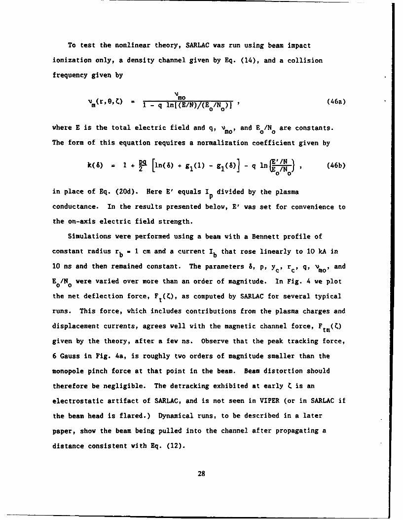
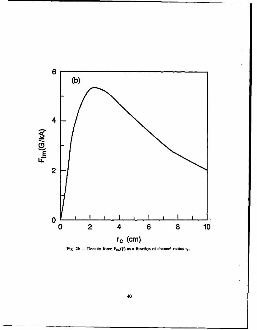
complexity. The principal additional information is that Ftm peaks when
the beam lies at the channel edge (where aln[N 0/N]/ar' peaks), and that Ftm
remains tracking and falls off nearly quadratically with yc when yc >> rc"
(The fall-off is faster, however, if the beam or channel is sharp-edged;
for example, Ftm equals zero if the beam is entirely outside the channel.)
The nonlinear result also confirms that F rises nearly linearly with the
chemistry parameter q and weakly with the channel depth. These
dependencies are shown in Fig. 2.
IV. FIELD EQUATIONS
A. Neglecting the Dipole Electric Field
The preceding tracking analysis is predicated on the assumption that
the electric field is symmetric about the beam and varies weakly with
radius r. Here we justify that assumption in the high-conductivity region
where the plasma return current and magnetic tracking are important. In
12

this region, the electrostatic potential and transverse electric field are
shorted out, leaving an axial electric field given by
z = BA (22)
The axial vector potential A and field Ez are determined by the Lorentz
wave equation, given in the frozen-field limit by14
VE2]A 4n + cbEz" (23)
The behavior of E is most easily analyzed using the linearizationz
employed in Sec. III-B. For small channel offsets, the vector potential
can be expanded in terms of monopole and dipole components:
A(r,O,) = A (r,) + Al(r,) cose + ... (24)
We again consider ohmic heating only, but for convenience, we replace Eq.
(18) with the modified form,
v=e, ) N12m mo [N(r,e) o j (25)
where q is constant and E0/N0 is a reference field strength. Imposing
expansion (9) for N and expansion (24) for A on Eqs. (22), (23) and (25)
produces, after some manipulation, the linearized equations
9r 9r c -- A -- Jb(r, ) , (26)
and
[ Lr - (1-j) 0dA, ! j (27)
13

where the monopole conductivity a(r,) is computed using Ez = -8A0 /K? in
Eq. (25) for Nm.
The characteristic relaxation length for the monopole potential A can0
be determined from Eq. (26). For self-similar Bennett profiles, this
length is given by
,w(O, )rb2
M= c n( + b2 /rb2) , (28)
where ;(O,) is the on-axis monopole conductivity, and b >> rb is the
radius within vhich space-charge neutralization occurs. The monopole
potential in this case is given by
Ao(r,') - n _b 2) (29)
where f is the plasma return-current fraction. The weak, logarithmic
dependence on r justifies treating the monopole electric field, -aA0/K, as
independent of r in the tracking analysis.
Similarly, the relaxation length of the dipole potential A1 can be
determined from Eq. (27), and for self-similar Bennett profiles is given by
= (-q) 2c (30)
This equation was first derived by Slinker et al. in studies of hose
instability. According to Eqs. (28) and (30), the dipole decay length Ml
is roughly an order of magnitude smaller than the monopole decay length
Sno" Neglecting the dipole electric field, -A 1/3C, relative to the
monopole field, -8A0 /9, is thus well Justified in the tracking analysis.
We state without proof that the dipole field acts to reduce the channel
14

force, and that the linearized tracking result (10) can be recovered from
Eq. (27) by dropping 8A1/Ot and using the fact that the local magnetic
deflection force equals -erdA.
B. Longitudinal Coupling and the Resistive Hose Instability
The channel tracking force calculated in the previous sections varies
with distance into the pulse. As the beam bends in response to this
force, it perturbs the electromagnetic fields. The plasma retards the
growth and decay of these perturbations and thus generates a longitudinal
coupling force, as the fields produced by early beam segments persist to
guide later segments. Although a detailed analysis of dynamical effects is
beyond the scope of this paper, the importance of coupling, both to
tracking and to the resistive hose stability, warrants a brief discussion.
Further discussion of coupling is given in the Appendix.
Coupling develops from dipole electric fields that are short-lived
("1 « ' o) relative to the monopole fields responsible for channel
tracking. As a consequence, the channel force exceeds the coupling force
as long as the channel offset and size remain modest, yc < rc " rbf and as
long as the simple chemistry model discussed earlier remains valid. As
discussed in Sec. V-A, however, the latter assumption fails at late C, as
higher-order chemistry causes the channel force to change sign and repel
the beam. The beam tail would then be ejected from the channel, even
though the head tracks, in the absence of coupling.
Although coupling is relatively unimportant early in the beam head, it
becomes important in the body where cumulative ionization produces a large
dipole decay length (1. If the channel force changes sign quickly over
M1' the coupling force will dominate and cause subsequent portions of the
15

beam to follov the head, regardless of the channel force. Coupling can
thus keep the entire beam in the channel, provided the channel force is
tracking initially and does not become detracking until ';R is large.
Although coupling keeps the beam together, it also drives the resistive
hose instability, as field perturbations become out of phase with beam
oscillations. 14'16 Because the phase lag and grovth rate of this
instability are governed by the magnetic dipole decay length 1' slov
changes in the channel force over ml should not excite strong hose grovth.
To the contrary, a channel force that is tracking and stronger than the
coupling force should reduce hose grovth by providing a fixed central axis
of attraction. Because hose is a convective instability and because .l
rises vith C, damping is most important in the beam head16 vhich is vhere
density tracking is strongest. Density tracking can thus suppress the hose
instability, as vell as keep the beam in the channel.
C. Electrostatic Forces
The preceding magnetic tracking analysis is restricted to the high-
conductivity region vhere the electrostatic fields and forces are small.
The electrostatic fields are not small, hovever, early in the beam head
vhere the conductivity is low. Nevertheless, several effects conspire to
reduce the impact of these fields on beam steering.
Electrostatic deflection forces arise as the channel conductivity
asymmetrically neutralizes the electrostatic field of the beam, thereby
polarizing the plasma charge. Because deflection develops from charge
polarization rather than from a unipolar charge, the deflection force
varies vith radius r, and hence its average value is small.
16

A second mitigating effect is that the plasma charge polarizes on a
monopole decay length given by
eo = c/4no, (31a)
but relaxes on a dipole decay length given by
=el . c/(1-q)2no. (31b)
These relationships can be derived using charge conservation and Gauss's
law.8 Because the two lengths are comparable, electrostatic deflection
decays nearly as rapidly as it arises, thus reducing its peak value. By
contrast, magnetic deflection attains full value because it decays slowly
relative to its growth, Mo > M"
A third limitation is the rapid growth of a from beam ionization. This
ionization quickly reduces el' thereby confining electrostatic deflection
to near the beam head. Because longitudinal coupling is not well developed
there, electrostatic deflection is ineffectual at steering the beam, as
well as weak.
V. GAS CHEMISTRY
A. Plasma-Electron Collision Frequency
The chemistry parameter q (or q) determines the sign and magnitude of
the channel force, and it thus largely determines the behavior of beams in
density channels in a given gas. In this section, we discuss the physical
17

basis for q and vmo, and determine their dependence on gas chemistry and
beam heating.
As noted earlier, the reduced collision frequency vm in a weakly
ionized gas equals an average of the plasma electron speed times the cross
section for momentum transfer to the gas molecules. The average electron
speed increases as the square root of the plasma electron temperature Te,
and for most gases this dependence causes vm to rise with Te. If vm rises
with Te, and if Te falls with gas density N, the parameter q in Eq. (6) is
positive, and the channel force is tracking. Otherwise, the force is
detracking.
The dependence of Te on N can be determined as follows. The plasma
electrons gain energy from both ohmic heating and direct beam heating, and
lose energy via collisions with the gas molecules. Ohmic heating derives
from the electric fields of the beam and plasma, while direct beam heating
is a by-product of beam impact ionization. Setting the cooling rate of the
plasma electrons equal to their heating rate yields
nNv c vE2 + f /e) N d (32a)
where v is the reduced inelastic cooling rate for the plasma electrons,
dc/dx is the reduced energy-loss function for the beam, and fh is the
fraction of deposited beam energy going into heating of the plasma
electrons. For a given gas, vc is a function of Te only, and de/dx is a
function of beam energy y only. For relativistic electron beams in air,
de/dx - 2-3 keV/cm-atm, and fh - 0.2.
Equation (32a) can be rewritten by dividing by nN and substituting
Eq. (1) for a. This yields a transcendental equation for the plasma
electron temperature Te
18

Tee2 2 f h de Jb,.c (Te) = I,, + • (32b)
To lowest order, the electric field E and the degree of ionization n/N are
independent of gas density N. As a consequence, lowering N raises the
heating rate on the right-hand side of Eq. (32b). Te is thus elevated in
regions of low N. The elevation is usually modest, however, because
rises rapidly with Te for temperatures of interest, Te - 1 eV. The weak
dependence of Te on N is responsible for the weak dependence of the
tracking force on N.
The chemistry parameter q is determined by Eqs. (6) and (32b) and the
dependence of vm and vc on Te. A much simpler estimate can be obtained,
however, by ignoring direct beam heating relative to ohmic heating. The
reduced collision frequency vm can then be expressed as a function of E/N,
without reference to Te. The neglect of direct beam heating is usually
valid when the beam and its fields are intense.
As an example, we plot in Fig. 3 the reciprocal of vm as a function of
the reduced field E/N in air. This curve was computed from the electron
drift speed, w = eE/mNvm, as calculated by Heylen 17 and tabulated by
Dutton.18 For convenience, E/N is normalized to the avalanche air
breakdown strength, Eb/N = 25 kV/cm-atm. Much above this field, avalanche-
induced detracking is likely, as discussed in the next section.
Figure 3 indicates that the chemistry model (18) is a crude but
adequat. approximation over limited ranges of E/N. In this model, the
parameters q and mo are weak functions of the electric field E(), which
is assumed to be independent of r. Typical values for air are q = 0.2 and
mo = 10-7 cm3/s for 0.1 Eb/N E/N < Eb/N; at lover fields, q a 0.5.
19

Replotting N3 to fit form (25) shows equally good agreement, with q = 0.2
at high fields and q = 0.5 at the lover fields. All of these parameters
are insensitive to the nature of the heating mechanism, provided the
cooling rate vc remains a strong function of Te. The addition of direct
beam heating should not, therefore, notably affect q, q, or Vmo"
B. Other Sources and Sinks of Ionization
Density tracking derives from simple but subtle chemistry properties,
and this raises the concern that other processes may be equally important.
In this section, we examine the effects of higher-order chemistry on n/N.
A more careful numerical analysis was performed by Keeley19 using a
detailed air chemistry code.
The behavior of n/N can be examined using a generalized continuity
equation for the plasma electrons:
8n - Nsb/e r ( -a)nN -r n 2 -. (nv) (33)
where si is an effective beam ionization cross section, v a is an electron
avalanche coefficient, 0a is an electron attachment coefficient, 0r is an
electron-ion recombination coefficient, and v is the plasma-electron fluid
velocity. In the preceding analysis, all terms on the right-hand side of
Eq. (33) were neglected. We separately assess each of these terms, using
the frozen approximation that B/8t = c UK.
The electron avalanche coefficient va is a strong function of E/N, and
thus it preferentially produces high n/N and high a in a low-density
channel. High channel conductivity increases the plasma return current in
the channel, which repels the beam. Avalanching must therefore be kept
small relative to beam ionization to keep the net channel force tracking.11
20

This requires high channel gas density N and modest electric field E. A
generally sufficient condition is
E/NC < 3(E b/N), (34)
where Eb/N is the minimum reduced field needed to initiate avalanching.
Condition (34) bounds the minimum channel depth for a given beam.
The effect of electron attachment, which converts free electrons to
essentially immobile negative ions, depends on the dependence of the
attachment coefficient ja on temperature Te and gas density N. If there is
little or no temperature dependence, the effect is detracking, because
attachment lovers n/N more outside the density channel than inside, so that
plasma return current flows preferentially in the channel. This detracking
becomes important at distances
C c/ aNo (35)
from the head.
Electron-ion recombination is detracking for the same reason. Namely,
it lowers n/N more outside the channel than in. Recombination becomes
important at
Sc e/rSiN b , (36)
where NJb is to be evaluated at its maximum value.
21

C. Plasma Dynamic Effects
In addition to the chemistry issues, the analysis neglects several
plasma dynamic effects. One of these is plasma electron convection
represented by the last term in Eq. (33). Convection perturbs n/N much
like a source or sink of ionization, but can usually be neglected because
the electron fluid velocity is typically small,
w/c< 10-3 . (37)
A related dynamical effect is electron pressure in Ohm's law. Electron
pressure can be neglected provided
Te << eErb, (38)
which is usually well satisfied except for very narrow beams.
A third dynamical effect is the finite time taken for plasma heating.
This time can be neglected provided the beam parameters vary slowly. A
sufficient condition, based on ohmic heating alone, is
c L << eEw/Te. (39)
The heating time for intense beams in air is typically sub-nanosecond.
A fourth effect is diffusion from beam ionization. Beam ionization
liberates energetic secondaries that produce additional ionization through
a cascade process. The total ionization is thus spread in space and time
inversely proportional to N.20'2 1 This spread preferentially reduces the
formation rate of a in the lo-density channel, an effect that should
enhance tracking.
22

A fifth neglected effect is momentum transfer between the plasma
electrons and ions. These Spitzer collisions become important at high
degrees of ionization, n/N > 10.2 , and cause vm to decrease rather than
increase with Te, thereby producing detracking. In initially un-ionized
gases, however, n/N is initially small, and hence collisions with ions are
usually negligible in the beam head where tracking is most important.
D. Channel Preionization
The assumption that the channel is un-ionized prior to beam injection
fails if the channel is deep and in thermodynamic equilibrium. In
equilibrium, a deep channel must be hot to maintain pressure balance with
the background gas, and hence it must be thermally ionized. Return
currents induced in this ionization can eject the beam.7 In 'his section
we determine how much preionization can be tolerated, and the limitations
that thermal preionization imposes on channel depth.
Channel preionization produces magnetic and electrostatic deflection
forces. As discussed earlier, the magnetic forces develop on the dipole
decay length 'Ml and relax on the monopole decay length mo', while the
electrostatic forces develop on the monopole decay length eo and relax on
the dipole decay length Cel" All the forces relax more slowly than they
develop.
At low levels of preionization, Cel initially exceeds mo , and thus the
electrostatic forces initially dominate. These forces are relatively
ineffectual, however, at steering the beam as discussed in Sec. IV-C.
By contrast, at high levels of preionization, &ml everywhere exceeds
el' and the magnetic forces then dominate everywhere. According to Eqs.
(30) and (31), Ml exceeds el for all provided
23

(1-q)n i r b/c > 1 (40)
where
2e n ieini (41)
Smv
is the conductivity resulting from the channel preionization, n i. Yu22
derived a variation of condition (40) and termed it the channel overheat
condition to signify the onset of strong magnetic detracking.
In a density channel, account must be taken of the density force Ftm.
To avoid repetition, we will not compute the detracking force from channel
preionization, but instead determine only when it is cancelled by Ftm.
For simplicity, consider a square density channel of radius r c that is
uniformly preionized and entirely inside a square beam of radius rb > rc -
Assuming beam impact ionization only, the uniform channel preionization,
ni/N, is supplemented by uniform beam ionization, n(Q)N. The gas-density
depression then perturbs the plasma current by an amount proportional to
the change in vm,
t E , L (42)
while the channel preionization perturbs the plasma current by
= E (hi) 1 (43)m vm(N)
The current 6 d produces tracking while 6Ji produces detracking.
24

Because the two currents have the same spatial distribbtion, the net
magnetic channel force equals zero when they cancel, 6ji+ 64 -O. The
transition from detracking to tracking thus occurs at the point t where
(t) = i [v M(N)IK~()
1 - q ln(N0/N)i q ln(N0/N) (44a)
=n~ v~ - I] (44b)
Form (44a) is based on chemistry relationship (18) for vm while form (44b)
is based on chemistry relationship (25). For deep channels, the force
typically transitions from detracking to tracking once n(Q) > ni.
As discussed earlier, the magnetic coupling force relaxes on the dipole
decay length y.m" Coupling is thus strong at t provided
(l-q)ai r b2 / c > t' (45)
This condition is stronger than the channel overheat condition (40),
provided Ct > rb. The latter proviso is in fact fundamental to the
analysis which presumes that the beam and plasma vary slowly, rb UK << 1.
The proviso fails only for extremely intense beams, for which displacement
currents and like effects must be incorporated.
For beams of interest, condition (45) is sufficient and generally
necessary for channel preionization to eject the entire beam. The head is
ejected because the net channel force is detracking, while the body is
25

ejected because it is coupled to the head. If condition (45) is not
satisfied, the detracking portion of the head is still ejected, but later
portions of the beam can track the channel. As discussed in the Appendix,
detracking condition (45) is imprecise because it does not account for the
different parametric dependencies of the channel and coupling forces. The
Appendix also shows that condition (45) can be difficult to meet.
Although conditions (40) and (45) differ significantly regarding ni/N,
the difference is often insignificant regarding allowed channel depth.
This is because ni/N is a strong function of N for a thermalized but weakly
ionized gas in pressure balance. To show this, consider the Saha equation
which states that the degree of thermal preionization ni/N in a weakly
ionized gas is proportional to exp(-W i2T ), where Vi is the gas ionization23
potential and T is the local gas temperature. The gas is weakly ionizedgonly if Tg << V 2, in which case ni/N is a very strong function of T . In
pressure balance, the gas density varies inversely with temperature,
N c T -1, so that ni/N varies strongly with N. For example, halving the
channel gas density at fixed pressure raises ni/N by over six orders of
magnitude at temperatures T < V./30. This strong variation usually causesg - 1
detracking condition (45) to be satisfied at channel temperatures much
above Wi/30. In hot air, for example, the lowest ionization potential is
i = -9.3 eV for NO, so that condition (45) is usually satisfied if the
channel temperature rises much above 0.3 eV. This temperature restriction
limits the depth of the channel, and thus limits the degree of beam-range
extension possible.
26

R. Chemistry Simary
The preceding analysis of gas chemistry suggests that the beam head is
likely to track the channel, as long as channel preionization and on-axis
avalanching are weak or absent. Although the beam body may experience
detracking from higher-order chemistry, longitudinal coupling causes the
body to follow the head. The sign and magnitude of the channel force is
thus most important in the region where coupling first dominates.
As discussed in Sec. V-B, we have verified the change in sign of the
tracking force at late C, as a function of various chemistry processes.
More exact chemistry analysis by Keeley 1 9 shows qualitatively similar
results. We have also performed dynamical simulations, to be reported in a
later paper, shoving that the entire beam can be pulled into the channel,
even when the channel force is detracking in the body. The first such
simulation was performed by Welch1 1 using the particle code IPROP. The
dynamical codes employ relatively simple chemistry, and they initially
failed to detect density tracking because vmwas taken to be constant.
VI. STATIC SIMULATIONS
A. Comparison with Analytic Theory
We have used two computer codes, VIPER1 6 and SARLAC,24 to compute the
average force produced by a density channel on a rigid-rod beam. For this
purpose, the beam is not propagated in z but is treated as frozen. In
dynamical runs, which will be described in a later paper, the beam is
allowed to move, although Maxwell's equations are still solved using the
frozen approximation, d/dz = 0. VIPER is a linearized code limited to
small beam displacements, while SARLAC is a nonlinear particle code.
27
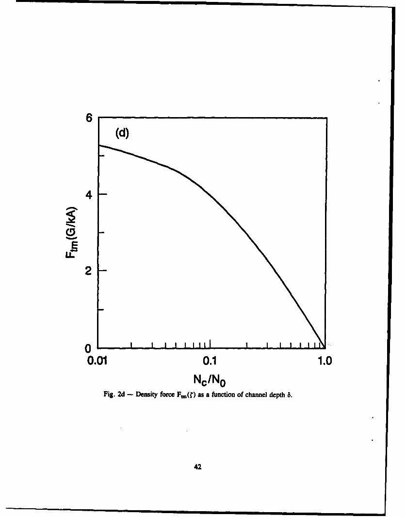
To test the nonlinear theory, SARLAC was run using beam impact
ionization only, a density channel given by Eq. (14), and a collision
frequency given by
Vv (r,%Q mo(4avm(r 'O, ) = 1 - q ln[(E/N)/(E0/No)] (46a)
where E is the total electric field and q, v o and E0/N0 are constants.
The form of this equation requires a normalization coefficient given by
k(S) = 1 + Eq [n(S) + gl(1) - gl(6)] - q ln o) , (46b)0 0
in place of Eq. (20d). Here E' equals I divided by the plasmaP
conductance. In the results presented below, E' was set for convenience to
the on-axis electric field strength.
Simulations were performed using a beam with a Bennett profile of
constant radius rb = 1 cm and a current Ib that rose linearly to 10 kA in
10 ns and then remained constant. The parameters 6, P, Yc, rc, q. vmo, and
E 0IN were varied over more than an order of magnitude. In Fig. 4 we plot
the net deflection force, Ft(C), as computed by SARLAC for several typical
runs. This force, which includes contributions from the plasma charges and
displacement currents, agrees well with the magnetic channel force, F ( )
given by the theory, after a few ns. Observe that the peak tracking force,
6 Gauss in Fig. 4a, is roughly two orders of magnitude smaller than the
monopole pinch force at that point in the beam. Beam distortion should
therefore be negligible. The detracking exhibited at early C is an
electrostatic artifact of SARLAC, and is not seen in VIPER (or in SARLAC if
the beam head is flared.) Dynamical runs, to be described in a later
paper, show the beam being pulled into the channel after propagating a
distance consistent with Eq. (12).
28

B. Gas Chemistry
To examine the effects of various chemistry processes on channel
tracking, we performed a series of runs using the linearized code VIPER.
In these runs, the beam current rose smoothly from zero to 20 kA, and the
beam radius fell smoothly from 2.65 cm to 1 cm, over a time scale of 10 ns
(A = 300 cm). The radius variation approximates the flaring that develops
naturally from weak pinching of the beam head.2 5 A Bennett profile was
used for the beam, and a Bennett profile of radius rc = 3 cm was used for
the channel depth. The ambient gas density was N = 1 atm, and the on-axiso
channel density was N = 0.3 atm.C
VIPER employs an air chemistry model2 6 containing all but the
convection term in the continuity equation (33). In Fig. 5 we plot the net
channel force as a function of C as various chemistry processes are turned
on separately and in total. Curve (a) plots Ft/y c using beam ionization
only; the force is everywhere tracking and agrees well with the analytic
predictions. Curve (b) adds electron attachment to 02 at a rate aNo -
5x10 7 s-I; attachment weakens the density channel force consistent with Eq.
(35), but does not cause actual detracking until much later. Curve (c)
shows the effect of electron-ion recombination with a rate coefficient 0r
10- 7 cm3 Is; recombination weakens the density channel force consistent with
Eq. (36), but again does not cause detracking until much later. Curve (d)
shows the effect of Spitzer collisions which, for the given parameters,
degrade detracking more than attachment or recombination. Curve (e) shows
the cumulative effect of all these processes. Observe that the channel
force remains tracking to C 600 cm, well into the region of strong
magnetic coupling. The entire beam is thus predicted to track the channel.
29

Shortening the beam rise time increases the inductive electric field
Ez . This raises Te and vm so that the plasma conductivity decreases, until
the field is so high that avalanching commences. For the beam described
above, VIPER shows avalanche-induced detracking if the beam current rises
faster than 30 kA/ns.
Adding channel preionization in excess of the overheat condition (40)
produced strong detracking of the beam head in the VIPER runs. Much lover
levels of prelonization produced weak channel forces that were attractive
or repulsive, on average, depending on and on the relative sizes of the
beam and channel. Preliminary dynamical simulations suggest, however, that
beam expulsion occurs only if the revised overheat condition (45) is met.
VII. CONCLUSION
The analytic and numerical work presented here strengthens the
theoretical base for the density tracking force discovered by Welch.1 1
Three chemistry properties underlie the effect. First, beam impact
ionization is the dominant source of ionization, and it produces a degree
of ionization that is symmetric about the beam. Second, the low-density
channel reduces the collisional cooling rate of the plasma electrons, thus
raising their temperature. And third, in most gases, the elevated
temperature raises the momentum-transfer collision frequency of the plasma
electrons, thereby lowering the plasma conductivity. The reduced
conductivity lowers the plasma return current in the channel, so that the
beam is magnetically attracted to the channel.
Several properties of density tracking make it unusually effective at
steering a beam. First, the density-channel force is strong, potentially
30

as strong as the radial pinch force that binds the beam together. Second,
the density force is long-lived, because it develops from beam ionization
and from magnetic monopole fields, rather than from magnetic dipole or
electrostatic fields. Third, the density force transitions smoothly to a
longitudinal coupling force that causes the beam body to follov the head,
regardless of the sign of the channel force in the body. Fourth, the
channel force is tracking in the beam head over a vide parameter range, and
remains tracking even as the beam pinches to a narrov radius. This trait
is especially important for beams that are radius-tailored 27 to reduce the
grovth rate of the resistive hose instability. Fifth, the density force
helps stabilize the hose Instability, particularly in the beam head vhere
stabilization is most needed. And sixth, density tracking develops
naturally out of the need to achieve range extension. The principal
requirements for density tracking to occur are low channel preionization,
veak on-axis avalanching, and a chemistry parameter q that is positive.
In short, density tracking should be capable, under appropriate
conditions, of keeping a stable, relativistic electron beam inside a
rarefied gas channel. Experiments11-13 designed to test the theoretical
predictions have verified the existence of a robust density-tracking force,
although they have not yet demonstrated range extension or clear evidence
of longitudinal coupling. The latter issues require longer propagation
distances and more stable beams.
31

ACKNOVLEDGENEw
We thank Drs. Bertram Hui and Martin Lampe for their insights on
channel tracking, Dr. Glenn Joyce for numerical consultations on SARLAC,
and Dr. A. Wahab Ali for his input on air chemistry. We also thank Drs.
Donald Murphy and Robert Meger for sharing their tracking results prior to
publication. In addition, we acknowledge useful discussions with Drs. Dale
Welch, Brendan Godfrey, and Douglas Keeley. This work was supported by the
Defense Advanced Research Projects Agency, ARPA Order No. 4395, Amendment
86, and monitored by the Naval Surface Warfare Center.
32

Appendix: Longitudinal Coupling
Longitudinal coupling arises when the beam and local pinch force are
misaligned. The misalignment produces a transverse restoring force,
denoted the coupling force, on the beam. For small misalignments, the
coupling force can be computed by linearizing the pinch force about the
beam axis. For a self-similar beam in the magnetic regime, the coupling
force takes the form
eln Yb - YnF a - (Al)
c rbe rb
where In is the net current, yn is its centroid, Yb is the beam centroid
(replacing yc in the earlier analysis), and el n/r c is the average magnetic
pinch force. Here we assume yb'yn << rb where Yb and yc are measured with
respect to a fixed (density-channel) axis. In addition, In is taken to be
symmetric about its centroid y n , and azimuthal asymmetries from a channel
are treated separately as a channel force.
We previously found that the magnetic dipole fields responsible for
magnetic coupling relax on a dipole decay length CM1" This suggests that
the net current centroid centers about the beam according to
aYn Yb - Yn
37 a *(A2)
Combining Eqs. (Al) and (A2) yields the approximation
F eI n 3yn (A3)c rbc rb a
A dynamical equation for ayb/az closes the problem.14'16
33

To calculate the channel force, we had assumed a rigid-rod beam
parallel to the channel. We could then ignore the coupling force Fco
because there was no tilt to either the beam or net current, ayb/aC I
ay n/aC = Yb- Yn However, a channel force that varies with C soon
causes the beam to separate from the net current and to tilt, so that
Yn * Yb' ayn/a? * 0, and Fc * 0. A large beam tilt, combined with large
Ml' can produce a coupling force larger than the channel force. In the
beam body, &Ml is large, and coupling usually dominates so that the body
follows the head.
The precise point at which coupling dominates a given channel force is
complicated by the different dependencies of the forces on the beam and
channel parameters. However, for a channel force that transitions from
detracking to tracking or vice versa, the coupling force is likely to
dominate provided the transition occurs quickly relative to Cml" In the
case of channel prelonization, condition (45) should be sufficient for
coupling to occur.
An interesting observation is that condition (45) can be met only at
high beam currents. To show this, let us use the left-hand side of the
continuity equation (33) to obtain the general expression
Ct > eclrb2n(t)ANsiIb(Ct), (A4)
depending on how fast Ib rises with t. If we now set n(t) ni, based on
Eq. (44), ye find that condition (45) can be rewritten as
mc3 v (N) vm(N)I(t) > = l7kA (A5)e e (l-q)s c (l-q)sic
34

Typical values in air are v = 10-7 cm3/s, q = 0.2, and si I 3x10-18 cm2,
suggesting that condition (45) is satisfied only for Ibt ) > 25 kA. If
the beam current never rises to this value, coupling requirement (45) is
never satisfied, and the beam body need not follow the head but is free to
track the channel. In principle, then, the body of modest-current beams
can track a density channel, regardless of preionization level.
Inpractice, however, high levels of preionization push Ct into regions
where higher-order chemistry causes the density force to become detracking.
The net channel force is then everywhere detracking, so that coupling is
irrelevant, and the entire beam is ejected from the channel. Furthermore,
high channel preionization will excite violent hose instability.16
35

References
1. E. P. Lee, Phys. Fluids 19, 60 (1976).
2. R. C. Smith and B. V. Schumacher, Nucl. Instrum. Methods 118, 73
(1974).
3. J. F. Lowry, J. H. Fink and B. V. Schumacher, J. Appl. Phys. 47, 95
(1976).
4. G. Bekefi, B. T. Feld, J. Parmentola and K. Tsipis, Nature 284, 219
(1980).
5. P. A. Miller, R. I. Butler, M. Cowan, J. R. Freeman, J. W. Poukey, T.
P. Wright and G. Tonas, Phys. Rev. Lett. 39, 92 (1977).
6. P. F. Ottinger and D. Mosher, Phys. Fluids 22, 332 (1979)
7. D. P. Murphy, M. Raleigh, R. e. Pechacek and J. R. Greig, Phys. Fluids
30, 232 (1987).
8. E. P. Lee, "Calculation of a Tracking Force," Lawrence Livermore
National Laboratory Report UCID-19674, January 1983, unpublished.
9. B. Hui and M. Lampe, J. Comp. Phys. 55, 328 (1984). See also B. Hui
and M. Lampe, "Numerical and Analytical Studies of Beam Channel
Tracking," Naval Research Laboratory Memo Report 5136, ADA139148
(1984).
10. J. A. Masamitsu, S. S. Yu and F. V. Chambers, "Beam Tracking Studies
with RINGBBARER II," Lawrence Livermore National Laboratory Report
UCID-19674, November 1982, unpublished.
11. D. R. Welch, F. M. Bieniosek and B. B. Godfrey, Phys. Rev. Lett. 65,
3128 (1990).
12. D. P. Murphy, R. E. Pechacek, D. P. Taggart and R. A. Meger, "Density
Channel Tracking Studies on Pulserad," Naval Research Laboratory Memo
Report 6770 (1991).
13. D. P Murphy, R. E. Pechacek, T. A. Peyser, J. A. Antoniades, M. C.
Meyers, J. Santos and R. A. Meger, Bull. Am. Phys. Soc. 35, 2071
(1990).
14. E. P. Lee, Phys. Fluids 21, 1327 (1978).
15. S. P. Slinker, R. F. Hubbard and M. Lampe, J. Appl. Phys. 62, 1171
(1987).
16. M. Lampe, W. Sharp, R. F. Hubbard, E. P. Lee and R. J. Briggs, Phys.
Fluids 27, 2921 (1984).
36

17. A. E. D. Heylen, Proc. Phys. Soc. (London) 79, 284 (1962).
18. J. Dutton, J. Phys. Chem. Ref. Data 4, 577 (1975).
19. D. A. Keeley, private communication.
20. S. P. Slinker, A. W. Ali and R. D. Taylor, J. Appl. Phys. 67, 679
(1990).
21. M. J. Berger, S. M. Seltzer and K. Maeda, J. Atm. Terr. Phys. 36, 591
(1974).
22. S. S. Yu, private communication.
23. See, for example, Y. B. Zel'dovich and Y. P. Raizer, Physics of Shock
Waves and High-Temperature Hydrodynamic Phenomena, W. D. Hayes and R.
F. Probstein, eds., Vol. I (Academic Press, New York, 1966), p. 195.
24. G. Joyce, R. Hubbard, M. Lampe and S. Slinker, J. Comp. Phys. 81, 193
(1989).
25. W. H. Sharp and M. Lampe, Phys. Fluids 23, 2383 (1980).
26. S. P. Slinker and R. F. Hubbard, "The Viper Conductivity Model," Naval
Research Laboratory Memo Report 5777, ADA167134 (1986).
27. M. Lampe, R. F. Fernsler and R. F. Hubbard, Bull. Am. Phys. Soc. 35,
2083 (1990). See also R. F. Hubbard, S. P. Slinker, R. F. Fernsler
M. Lampe and G. Joyce, op. cit.
37

a E z(r,0)
8 1b
Fig. 1 - An element of plasma current. A, at (r, 0) deflects a beam ring of radius r. Only currents
outside the ring, r' > r, deflect it. The direction 0 = 0 is defined by the line from the beam centroid
(0,0) to the density-channel centroid (y,' 0).
38

5
4
~m3
ELC 2
0 1 2 3 4 5
YC (cm)Fig. 2a - Density force Ftm(r) as a function of channel offset Yc. Ft. is given in units of Gauss perkA of plasma return current, calculated using Eqs. (19)-(20) with the following nominal parameters:rb = =c 1 , cm, q = 0.2, 5 = 0.1, and p = 1.
39
6
4
E
0 2 4 6 8 10
rc (cm)Fig. 2b - Density force Ftm(r) as a function of channel radius r,.
40

25
20
~15
ELC 10
5
O0 I
0.0 0.2 0.4 0.6 0.8
qFig. 2c - Density force Ft.(r) as a function of chemistry parameter q.
41
6(d)
E
24

4 x10⁷
E3
E
0.01 0.1 1.0
( Eb/N}
Fig. 3 - Thie inverse of the reduced collision frequency 'mas a function of electric field in air.
43
6(a)
LC'
29
0
Fig. 4a - Typical comparison plots of the total numerical tracking force Ft [solid line] and thetheoretical magnetic force Ft. [dashed line] for 'y, - 1, r, = 2, q = 0.2, 6 = 0. 1, and p = 1.T1he lengths y, and r, are normalized to the beam radius, rb = 1 cm.
44

0.6
0.5 1
0.4 /4
/ 9%---- 0.
0.2
0.2070) 150300 45
(CMFi.4b-Tyialcn~rso losofte oalnmeialtacm fre t[sld ie]ad h
0 1~5 0 5

0.5
0.4
0.3
0.2
0.1
0.00 150 300 450
C (cm)Fig. 4c - Typical comparison plots of the total numerical tracking force, F, [solid line] and thetheoretical magnetic force Ft., [dashed line] for y, = 0.1, r. = 0.5, q + 0.4, 6 = 10-5, andp - 0.2.
46

5 x10⁻²(d)
4
3\
2
1
o0 . 150 300 o
(CM)Fig. 4d -- Typical comparison plots of the total numerical tracking force Ft [solid line] and thetheoretical magnetic force Ft. [dashed line] for yc =f 0. 1, rc = 2, q =f 0.01, 6 =f 0.63, and p =f 5.
47

90 a80
70
ow%60E0"-ft50
~40
~30
20
10
00 300 600 900
S(CM)Fig. 5 -The density force F, as a function of air chemistry: (a) beam impact ionization only; (b)attachment; (c) electron-ion recombination; (d) Spitzer collisions; and (e) all of the above.
48