nrc medium voltage circuit breaker training chapter 2closing shaft and link • the closing shaft is...
TRANSCRIPT
NRC Medium Voltage Circuit Breaker Training
CHAPTER 2
CIRCUIT BREAKER COMPONENTSand
OPERATION
Learning Objectives
• Describe different breaker closing methods.• Be able to recognize and describe the function of breaker
mechanical components. • Know the difference between the line and load side primary
conductors.• Understand how the breakers are inserted into the switchboard• Understand how the breakers are inserted into the switchboard.• Understand the difference between Primary and Secondary current
carrying components.• Understand the difference between main and arcing contacts.• Understand the function of a puffer.• Understand the operating sequence of an operating mechanism.
Circuit Breaker Operation
• Breakers can be operated two ways• Manual Operation• Manual Operation• Electric Operation
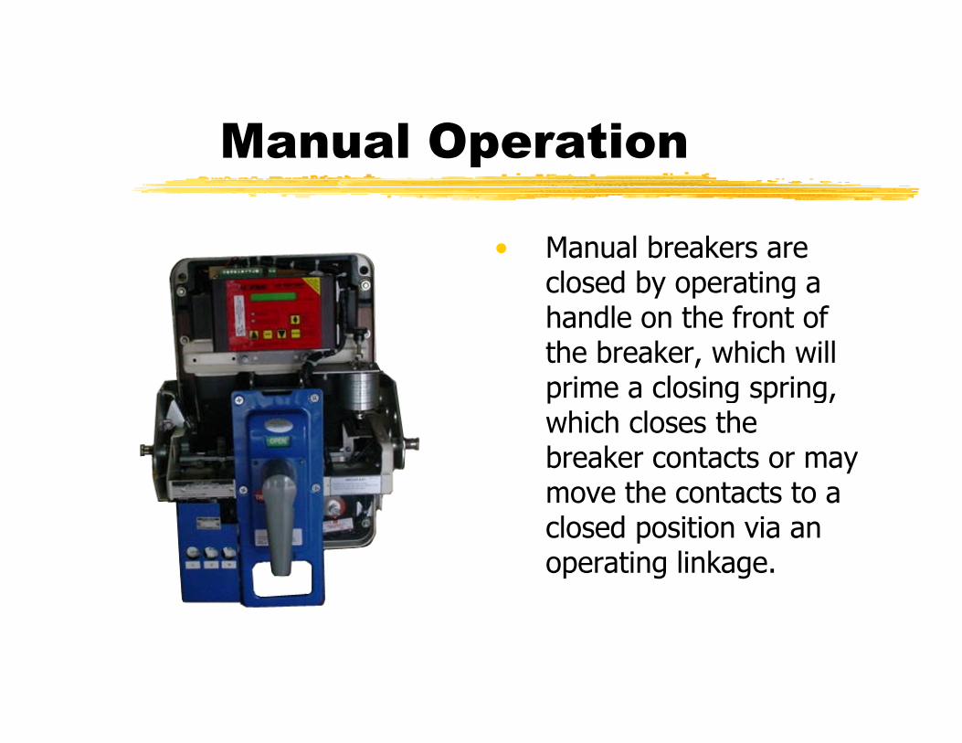
Manual Operation
• Manual breakers are closed by operating a handle on the front of the breaker, which will prime a closing spring, which closes the breaker contacts or may move the contacts to a closed position via an operating linkage.
Medium voltage breaker manual operation
• Manual operation is primarily for maintenance and is performed by compressing the closing spring with a manual closing spring charging device, closing and tripping mechanisms are normally dual operating and manual closing and tripping operation is performed from the breaker front plate.
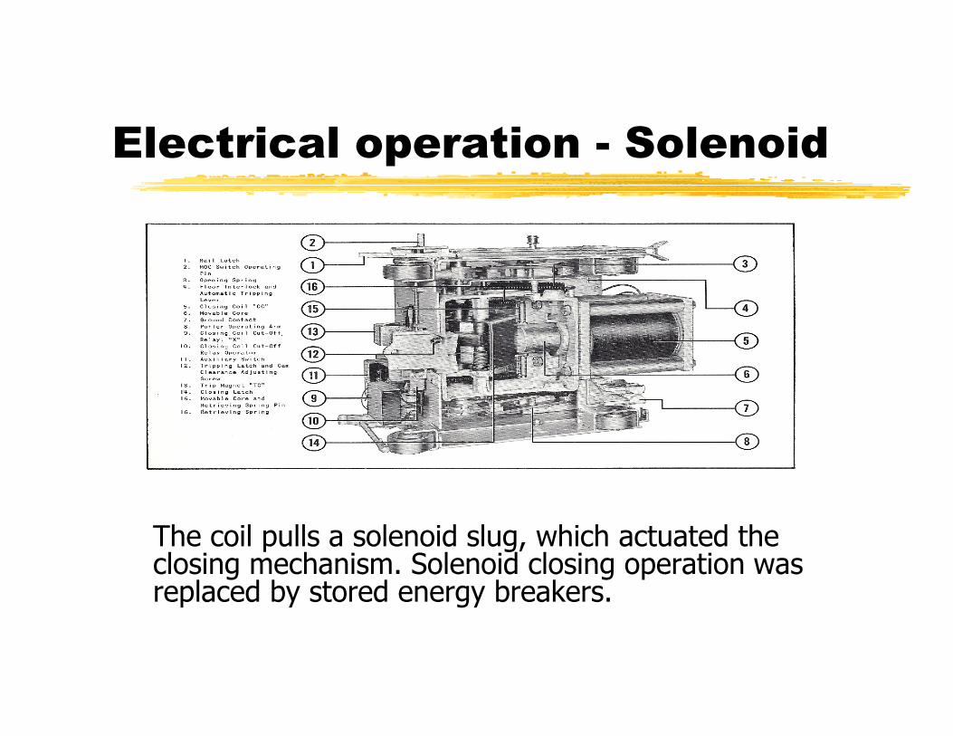
Electrical operation - Solenoid
The coil pulls a solenoid slug, which actuated the closing mechanism. Solenoid closing operation was replaced by stored energy breakers.

Electrical operationStored energy closing

MAIN CURRENT CARRYING COMPONENTS
The phase or pole design in all breakers will consist of some or all of the following components.P i di t• Primary disconnects.
• Primary conductors (Bushing)• Moving contact arm• Contacts • Puffer device
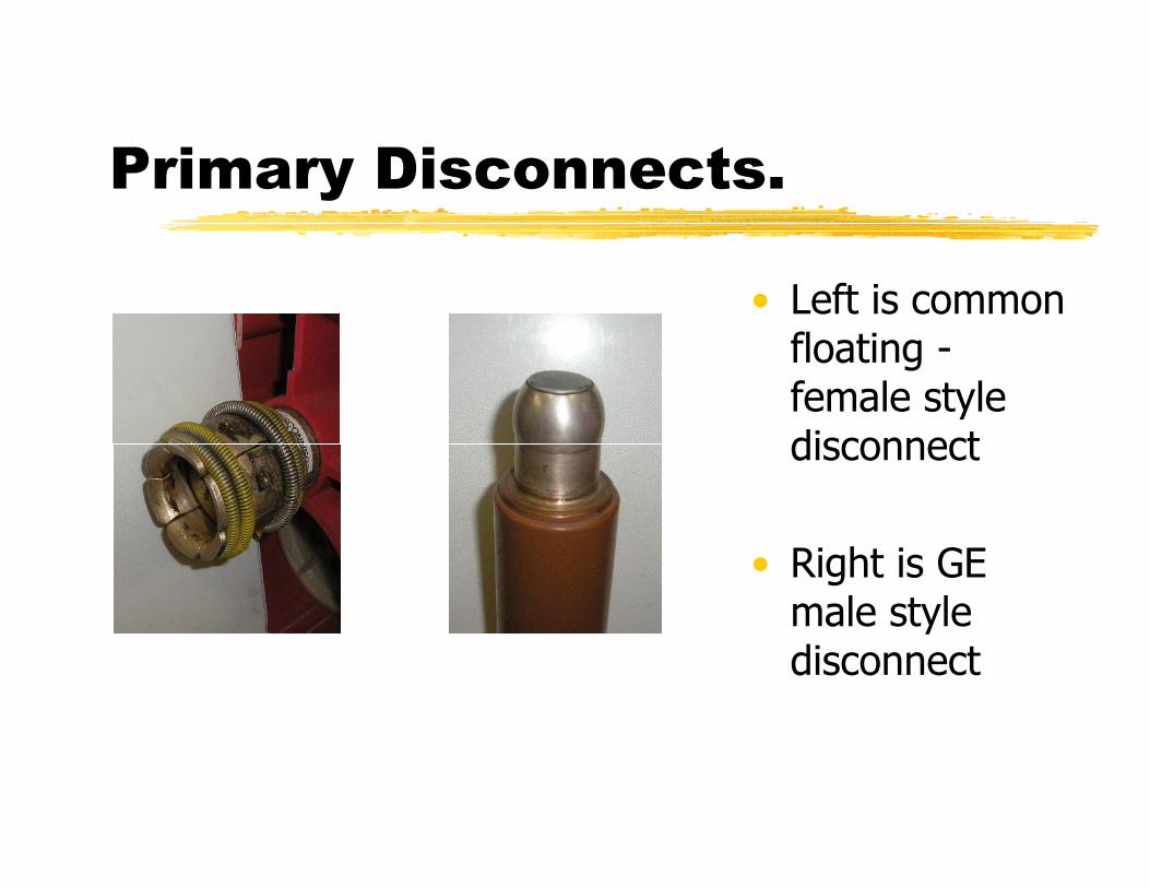
Primary Disconnects.
• Left is common floating -female style disconnectdisconnect
• Right is GE male style disconnect

Primary bushing and puffer device
• This is the rear of an ABB 5 HK breaker. There are 6 primary bushings with primarybushings with primary disconnects attached
• White round discs in between the primary bushings are puffer pistons
Moving contact arm and contacts
• The moving contact arm is silver plated copper d t t th i b hi t i t
We will be using the Magne-Blast and DHP Contact structure to demo the contact assemblies
and connects to the primary bushing at a pivot point on the load side primary conductor.
• Arcing and main contacts are connected to the stationary side bushing and the moving contact arm

Vacuum Breaker Contacts
• There are only main contacts within a vacuum bottle. The commonly used materials for vacuum breakers arevacuum breakers are either copper-bismuth or copper-chrome alloys. The shape is also important and two basic shapes are used cupped axial magnetic design and a slotted design.

Closing Shaft and Link
• The closing shaft is the device that connects the operating mechanism to the insulated links that
h i Th l i h f
We will be using the class breakers to show closing shaft designs
operate the moving contacts. The closing shaft has different names depending on the breaker manufacturer:
• Crank shaft • Jack shaft • Pole operating shaft • Main Shaft
Operating Mechanism
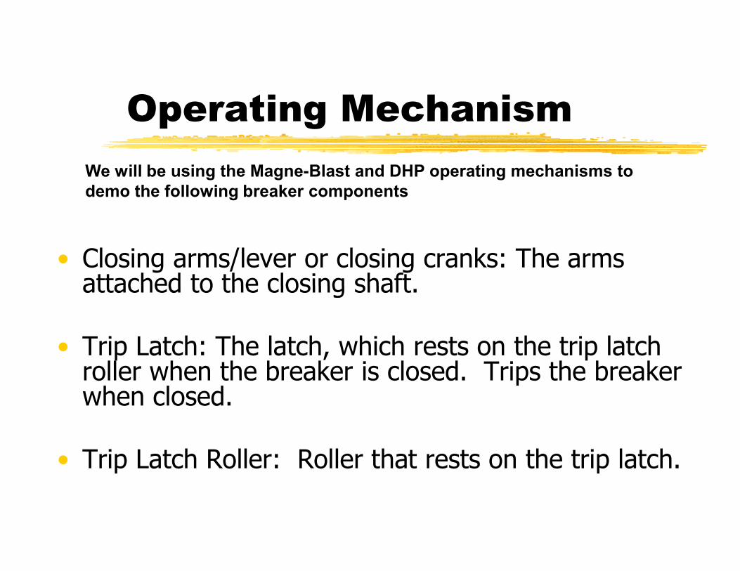
• Closing arms/lever or closing cranks: The arms attached to the closing shaft
We will be using the Magne-Blast and DHP operating mechanisms to demo the following breaker components
attached to the closing shaft.
• Trip Latch: The latch, which rests on the trip latch roller when the breaker is closed. Trips the breaker when closed.
• Trip Latch Roller: Roller that rests on the trip latch.

Operating Mechanism-continued
• Closing Roller: The roller on the mechanism linkage. The closing roller rides on the closing cam during the close operation.
• Closing Cam: The closing cam is a drop camClosing Cam: The closing cam is a drop cam shape design and pushes the breaker linkage to the close position.
• Prop Larch (DHP = Tripping cam): Latch used to hold the mechanism in the closed position after closing to allow the mechanism to recharge.
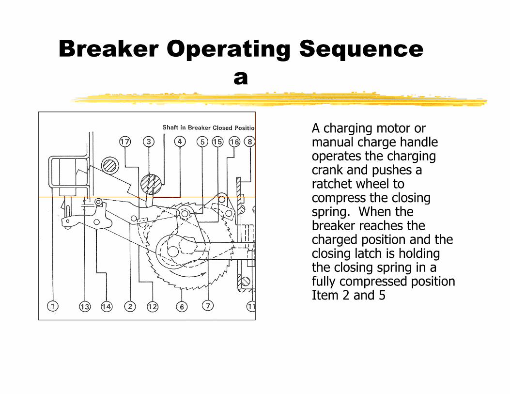
Breaker Operating Sequence a
A charging motor or manual charge handle operates the charging crank and pushes a ratchet wheel to compress the closingcompress the closing spring. When the breaker reaches the charged position and the closing latch is holding the closing spring in a fully compressed position Item 2 and 5

Breaker Operating Sequence b
• The trip latch will now be in a position to hold the mechanism in a closed positionin a closed position when the close operation is initiated Item 10 and 18

Breaker Operating Sequence c
• When the close latch is moved the closing spring will drive a closing cam and engages the closing mechanism linkage, the mechanism linkage is attached to the operating shaft, which in turn is attached to the moving contacts, and the breaker will close. (Figure 2-7c)
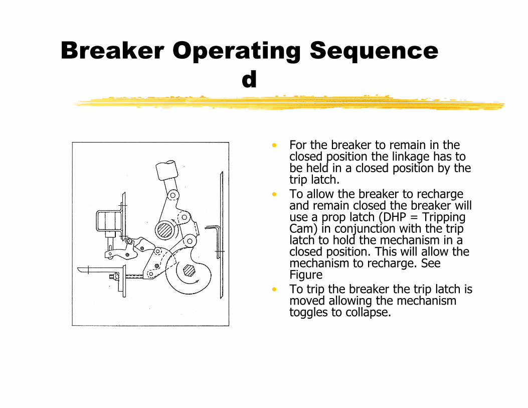
Breaker Operating Sequence d
• For the breaker to remain in the closed position the linkage has to be held in a closed position by the trip latch.
• To allow the breaker to recharge and remain closed the breaker willand remain closed the breaker will use a prop latch (DHP = Tripping Cam) in conjunction with the trip latch to hold the mechanism in a closed position. This will allow the mechanism to recharge. See Figure
• To trip the breaker the trip latch is moved allowing the mechanism toggles to collapse.
Springs
• Closing Springs: provide the energy to close the contacts
• Opening Springs: open the breaker during a trip operationoperation
• Other breaker Springs: • Trip Latch Spring: Resets and holds trip latch in
position.• Close Latch Spring: Resets and holds close latch in
position.• Prop Latch Spring: Pulls the prop on to latch

RACKING MECHANISM
• This is a ABB HK racking mechanism
• During work shop the DHP R kiDHP Racking (Levering Device) mechanism will be shown