nrc inspection manualon january 30, 2012, byron station, unit 2 experienced an automatic reactor...
TRANSCRIPT
Issue Date: 10/31/17 1 2515/194
NRC INSPECTION MANUAL EEOB TEMPORARY INSTRUCTION 2515/194
INSPECTION OF THE LICENSEES’ IMPLEMENTATION OF INDUSTRY INITIATIVE ASSOCIATED WITH THE OPEN PHASE CONDITION DESIGN VULNERABILITIES IN
ELECTRIC POWER SYSTEMS (NRC BULLETIN 2012-01)
Effective Date: November 1, 2017 CORNERSTONE: Initiating Events, Mitigating Systems APPLICABILITY: This Temporary Instruction (TI) applies to the holders of operating licenses
for operating nuclear power reactors who have implemented actions to protect against open phase conditions (OPCs). This TI is to be performed at all current operating plants with the exception of Seabrook Station, Unit 1, plants seeking NRC approval in accordance with 10 CFR 50.90, and sites that have informed the NRC of their intent to decommission prior to 01/30/2020.
2515/194-01 OBJECTIVE
01.01 To verify that licensees have appropriately implemented the Nuclear Energy Institute
(NEI) voluntary industry initiative (VII) including updating their licensing basis to reflect the need to protect against OPCs.
01.02 To gather the information necessary for NRR staff to determine whether the licensees
adequately addressed potential OPCs.
2515/194-02 BACKGROUND Event at Byron Nuclear Plant On January 30, 2012, Byron Station, Unit 2 experienced an automatic reactor trip from full power because the reactor protection scheme detected an undervoltage condition on the 6.9 kilovolt (kV) buses that power reactor coolant pumps (RCPs) B and C (undervoltage on two of four RCPs initiate a reactor trip). Byron Station is a two-unit pressurized water reactor plant. The electrical distribution system for each unit consists of four non-safety 6.9-kV buses, two non-safety 4 kV buses, and two engineered safety features (ESF) 4-kV station buses. During normal plant operation, the safety (or ESF buses) and non-safety buses (or non-ESF) are powered from the Unit Auxiliary Transformers (UATs). On the day of the event, two non-ESF 6.9-kV station buses that power two of the RCPs and the two 4-kV (ESF and non-ESF) buses were supplied by station auxiliary transformers (SATs) connected to the 345-kV offsite power switchyard (Figure 1 below). The other two 6.9-kV and 4-kV buses were powered from the UATs. The undervoltage condition on the SAT powered buses was caused by a broken inverted porcelain insulator stack of the phase C conductor for the 345-kV power circuit that supplies both SATs. The insulator failure caused

Issue Date: 10/31/17 2 2515/194
the associated phase C conductor to break off from the power line disconnect switch resulting in a high impedance ground fault through the fallen phase C conductor and a sustained open phase condition (OPC) on the high voltage side of the SAT. The open circuit created an unbalanced voltage condition on the two 6.9-kV non-ESF RCP buses and the two 4.16-kV (ESF and non-ESF) buses. After the reactor trip and subsequent generator trip, the two 6.9 kV buses, which were aligned to the UATs, automatically transferred to the SATs, as designed. As a result of the open circuit on C phase, the load current in phases A and B increased and caused the remaining two operating RCPs to trip on phase overcurrent. In the absence of any operating RCPs, control room operators performed a natural-circulation cooldown of the plant. The SATs continued to power the 4.16 kV ESF buses A and B because of a design vulnerability that did not isolate the safety related buses from the degraded offsite power system. Some ESF loads that were energized relied on equipment protective devices to prevent damage from an unbalanced overcurrent condition. The phase overcurrent condition caused by the OPC actuated relays to trip several ESF loads. Approximately 8 minutes after the reactor trip, the control room operators diagnosed the loss of the phase C condition and manually tripped circuit breakers to separate the unit buses from the offsite power source. When the operators opened the SAT feeder breakers to the redundant 4.16-kV ESF buses, the loss of voltage relays started the emergency diesel generators (EDGs) and restored power to the ESF buses. If the condition had been allowed to persist for an additional few minutes, damage to the RCP seals could have occurred through a loss of RCP seal cooling water. This in turn, could have resulted in a loss of coolant from the RCP seals in the containment building.
Figure 1. Simplified Schematic of Electrical busses associated with one train (Unit 2)

Issue Date: 10/31/17 3 2515/194
A second event also occurred at Byron Station Unit 1 on February 28, 2012. This event was also initiated by a failed inverted porcelain insulator that resulted in an open phase as well as a phase-to-ground fault on the line side of the circuit. In this event, the fault current was high enough to actuate protective relaying on the 345-kV system. The 4.16-kV ESFs buses experienced a loss of voltage (LOV) caused by the opening of 345-kV system breakers, which resulted in a separation of the SATs from the 4.16-kV buses. The two EDGs started and energized the 4.16-kV ESF buses, as designed. Operating Experience A review of other operating experience identified design vulnerabilities associated with single phase open circuit conditions at South Texas Project (South Texas), Unit 2 (Licensee Event Report (LER) 50 499/2001 001, Agencywide Documents Access and Management System (ADAMS) Accession No. ML011010017); Beaver Valley Power Station, Unit 1 (LER 50 334/2007 002, ADAMS Accession No. ML080280592); and a single event that affected Nine Mile Point, Unit 1 (LER 50 220/2005 04, ADAMS Accession No. ML060620519) and the neighboring James A. Fitzpatrick Power Plant (LER 50 333/2005 06, ADAMS Accession No. ML060610079). These events involved offsite power circuits that were rendered inoperable because of an open circuit in one phase. In each instance (except South Texas, Unit 2), the condition went undetected for several weeks because offsite power was not aligned to the ESF buses and therefore unloaded during normal operation and the surveillance tests, which recorded phase-to-phase voltage, did not identify the loss of the single phase. At South Texas, Unit 2, offsite power was normally aligned to the ESF and non-safety plant buses, and the operator manually tripped the reactor when the OPC tripped the three circulating water pumps. Operating experience has identified several international events and the International Atomic Energy Agency (IAEA) has published a report titled “Impact of Open Phase Conditions on Electrical Power Systems of Nuclear Power Plants,” detailing the significance and consequences of such events (Reference: https://www.iaea.org/publications/11026/impact-of-open-phase-conditions-on-electrical-power-systems-of-nuclear-power-plants. Industry Initiative to Resolve OPC Design Vulnerability Issue In response to the Byron event, the industry’s chief nuclear officers approved a formal initiative to address OPCs. This initiative was communicated to NRC by the NEI in letter dated October 9, 2013 (ADAMS Accession No. ML13333A147) and acknowledged in the NRC letter dated December 19, 2013 (ADAMS Accession No. ML13340329). This letter further indicated that this approved initiative commits each licensee to develop a proactive plan and schedule for addressing the potential design vulnerabilities associated with OPCs. Subsequently, on March 16, 2015, NEI informed the NRC (ADAMS Accession No. ML15075A454) that, to provide adequate time for OPC implementation, the completion schedule would be revised to December 31, 2018. The industry’s chief nuclear officers approved this schedule change in Revision 1 of its document. The industry initiative described in the March 16, 2015 NEI letter is the VII referred elsewhere in this TI.

Issue Date: 10/31/17 4 2515/194
Failure Modes and Consequences of OPC An OPC may result in challenging plant safety. Operating experience in different countries has shown that the currently installed instrumentation and protective schemes have not been adequate to detect this condition and take appropriate action. An OPC that affects the safety function, if not detected and disconnected promptly, represents a design vulnerability for many nuclear power plants (NPPs). It may lead to a condition where neither the offsite power system nor the onsite power system is able to support the safety functions, and could propagate to station blackout. The January 2012 operating event at Byron Station, Unit 2, revealed a significant design vulnerability where an OPC in the plant’s offsite power supply caused a loss of certain safety functions powered by the site’s alternating current (ac) electric power system. The loss of these safety functions occurred because the ESF electric power system's protection scheme was unable to detect and isolate the loss of a single phase between the transmission network and the onsite power distribution system. The resulting degraded and unbalanced voltage conditions on redundant ESF buses led to the tripping of equipment required for normal plant operations and safe shutdown. The inability of the protection scheme to detect an OPC and automatically transfer power from the affected electric power system allowed the degraded offsite power system to remain connected to ESF buses, and prevented other onsite ac sources (e.g., Emergency Diesel Generators (EDGs)) from starting and powering these buses. As a result, certain safety-related and important to safety equipment required for safe operations remained powered by the degraded ac source. The ability of this equipment to perform the required safety functions was questionable as the internal protective features installed to prevent damage from overheating would have either actuated and locked-out the vulnerable components or, depending on the setpoint, allowed continued operation and thereby risk damage from overheating. Furthermore, equipment required for safe shutdown was also at risk of being unavailable for an extended period of time even after the restoration of an operable power source, since operator actions would be required to manually reset tripped protective devices. In response to the Byron event, the U.S. and international nuclear industry evaluated the consequences of an OPC and an unbalanced voltage condition in a three-phase power system. Continued operation for an extended duration with unbalanced voltage conditions can damage equipment as a result of overheating and vibration, or result in the inadvertent trip of electrical equipment and cause a plant transient. Redundant equipment important to safety which is supplied from a common power source may be damaged when exposed to the unbalanced voltage conditions. The operators may not always be able to respond promptly to prevent multiple equipment damage due to a lack of information available from existing measurements, indications, and automatic actions. The type of fault or transformer winding configuration and grounding techniques can result in low voltage unbalance conditions (e.g., during light load or no-load conditions), and the degraded conditions can go undetected for a long period of time and may not be revealed until the transformer load is increased. The effect of OPC on the operating equipment, typically induction motors, depends on a number of factors. An OPC in fully loaded power supply system can result in high current flow in at least one of the three phases of rotating motors. This higher than normal current may actuate the protective scheme, which disconnects the loads from the degraded source. However, the magnitude of the current is dependent on the type of transformer and system configuration to the associated feeder circuits and in some cases the current flow may not actuate protective relaying and result in excessive heating of the motor windings. Unbalanced voltages applied to a three–phase induction motor result in unbalanced currents in the stator windings and introduce a negative sequence voltage. The negative sequence voltage produces a flux rotating

Issue Date: 10/31/17 5 2515/194
in the opposite direction of the rotation of the rotor, producing additional currents and heating. The unbalanced conditions result in overheating of the motor. If the protective scheme actuates and disconnects the load important to safety from the degraded power source, the safe shutdown capability of the plant may be compromised as the affected component may not be available until manual actions are taken to identify the cause of the trip, reset the protective relaying and close the appropriate breaker. If the circuit with an OPC is in standby mode or lightly loaded, then the low magnitude of current flow in the degraded circuit may not result in sufficient unbalance to actuate any protective device. The OPC may therefore not get detected until a change in plant state or a bus transfer to the offsite standby source results in increasing the load current in the circuit. Once the circuit has increased demand, then the running motors may trip due to overcurrent protection actuation or sustain winding damage due to heating effects. The operating experience as well as results from analytical studies has confirmed that voltages can be present on all three phases downstream of the OPC due to the interaction of magnetic fields in transformers and three phase loads. In some cases, all three phases on the low voltage winding may have balanced voltages in all phases under no load or lightly loaded conditions. With this regard, the voltage can be regenerated through the systems, but depends upon: • Transformer winding, core configuration, and rated power • System grounding arrangements • Transformer loading, size and type of loads (e.g. motor or static) • Properties of cables and overhead lines (capacitance, inductance) • Location of the open phase. NRC Actions Based on the Byron Station operating event, the Nuclear Regulatory Commission (NRC) staff issued Information Notice 2012-03, “Design Vulnerability in Electric Power System,” dated March 1, 2012 (ADAMS Accession No. ML120480170). On July 27, 2012, the staff issued Bulletin (BL) 2012-01, “Design Vulnerability in Electric Power System” (ADAMS Accession No. ML12074A115). Specifically, the NRC asked licensees to provide information by October 25, 2012, on (1) the protection scheme to detect and automatically respond to a single-phase open circuit condition or high impedance ground fault condition on GDC 17 power circuits, and (2) the operating configuration of ESF buses at power. The Electrical Engineering Branch staff reviewed the information that NRC licensees provided and documented the details of this review in NRC BL 2012-01, in the summary report dated February 26, 2013 (ADAMS Accession No. ML13052A711). In SECY-16-0068, dated May 31, 2016 (ADAMS Accession No. ML15219A327), the staff requested Commission approval of an interim Enforcement Policy (IEP), applicable to all operating reactors, to allow the NRC to exercise enforcement discretion for certain instances of noncompliance with the requirements specified in the technical specifications (TS) for electrical power systems (typically TS Section 3.8) and action statement(s) associated with “AC Sources—Operating” and “AC Sources—Shutdown,” and with GDC 17. This IEP could be applicable to certain instances of nonconformance with the principal design criteria specified in the UFSAR.

Issue Date: 10/31/17 6 2515/194
On March 9, 2017, the Commission issued (ADAMS Accession No. ML17068A297) Staff Requirements Memorandum (SRM) SECY 16-0068, “Interim Enforcement Policy for Open-Phase Conditions in Electric Power Systems for Operating Reactors.” The Commission disapproved the staff’s request to establish an IEP for the purpose of exercising enforcement discretion for purported noncompliance with NRC requirements and nonconformance with design criteria during the pendency of licensee implementation of actions to address an OPC. The SRM stated the following:
“Going forward, the staff should verify that licensees have appropriately implemented the voluntary industry initiative. If the staff determines that a licensee does not adequately address potential OPCs, including updating the licensing basis to reflect the need to protect against OPCs, the staff should consider the appropriate regulatory mechanism to impose the necessary requirements to protect against OPCs using the current guidance on such matters from the Office of the General Counsel. The staff should provide the Commission with a notation vote paper if this situation arises for any licensee or licensees, with options, including the staff's recommended path forward. In addition, if disagreements arise between the staff and the industry during implementation of the voluntary industry initiative, and the related issues have policy implications, the staff should promptly raise such issues to the Commission for resolution. Once satisfactory implementation of the technical resolution has been verified for each licensee, the associated NRC Bulletin should be closed. The staff should update the Reactor Oversight Process to provide periodic oversight of industry's implementation of the OPC initiative.”
The staff has written this TI for inspectors to verify whether licensees have appropriately implemented the technical resolution of OPC design vulnerability as discussed in their industry initiative document at each operating reactor unit. A TI was chosen as verification of implementation would closely resemble a plant modification inspection. The inspection program is well suited to cover this verification, and while inspectors are on site they will able to gather data to support closure of the Bulletin. Covering both the data gathering and verification of the VII implementation creates efficiencies and saves resources for both the licensee’s and NRC. 2515/194-03 INSPECTION REQUIREMENTS AND INSPECTION GUIDANCE General Guidance. Preparation: Prior to arrival on site, request that key documents be available for on-site inspection (e.g., calculations, analyses, drawings, procurement specifications, test reports, modification packages including 10 CFR 50.59 evaluations, and maintenance, surveillance and test procedures). Arrange with the licensee to have appropriate design, maintenance, and operations staff on-site to support the inspection. Request a brief licensee presentation after entrance meeting describing their electric power system design; normal plant operating alignments; OPC design schemes installed to detect, alarm and actuate; bus transfer schemes; maintenance and surveillance requirements; and licensing basis changes to Updated Final Safety Analysis Report (UFSAR) and Technical Specifications (TS). Conduct: This TI will be initially performed at a small number of sites which have different OPC detection and protections schemes in order to gain insights as to whether policy issues may

Issue Date: 10/31/17 7 2515/194
exist that would necessitate further Commission involvement as specified in Staff Requirements – SECY-16-0068 – Interim Enforcement Policy for Open Phase Conditions in Electric Power Systems for Operating Reactors (ADAMS Accession No.ML15219A327). The initial sites selected for implementation will be identified prior to the issuance of this TI for implementation. This TI has two parts (1) VII inspection and (2) information gathering. Issues identified during the inspection of the VII will be documented as unresolved items (URIs) and then reviewed by a panel to determine whether they represent performance deficiencies. The URIs will then be appropriately dispositioned using Inspection Manual Chapter (IMC) 0612. Once all initial sites have been inspected using Section 03.01 of this TI and all resulting initial inspection issues have been reviewed by the panel, NRR staff will review both the inspection results and the information collected in Section 03.02 of this TI to determine if the VII adequately addressed potential OPCs. Should the NRC staff identify issues with the adequacy of the VII implementation to address OPCs, the NRC will seek resolution from the licensees and NEI. As directed by the Commission in SRM SECY-16-0068, should disagreements arise between the NRC staff and the industry during implementation of the voluntary initiative, and the related issues have policy implications, the NRC staff will promptly raise such issues to the Commission for resolution. If the NRR staff determines after review of the initial inspection results and information collected that there are no policy issues and the plant modifications implemented in response to the VII are appropriate, the remaining plants will then be inspected only for section 03.01 of this TI to verify that the VII was appropriately implemented at remaining plants. This TI may be updated to incorporate lessons learned from the initial inspections. 03.01 Voluntary Industry Initiative (Part 1). Note: Issues identified during the inspection of the VII will be documented as URIs. Determine whether the licensee appropriately implemented the VII dated March 16, 2015 (ADAMS Accession No. ML15075A454) by verifying the following:
a. Detection, Alarms and General Criteria.
1. Either:
OPCs are detected and alarmed in the control room. OR
(a) The licensee has demonstrated that OPCs do not prevent the functioning of important-to-safety SSCs AND
(b) OPC detection will occur within a reasonably short period of time (e.g., 24 hours) AND
(c) The licensee has established appropriate documentation regarding OPC detection and correction.
2. Either:
Issue Date: 10/31/17 8 2515/194
Detection circuits are sensitive enough to identify an OPC for credited loading conditions (i.e., high and low loading). OR If automatic detection may not be possible in very low or no loading conditions when offsite power transformers are in standby mode; automatic detection must happen as soon as loads are transferred to this standby source. Additionally, the licensee has established appropriate shiftily surveillance requirements to look for evidence of OPCs.
3. OPC design/protective schemes minimize misoperation or spurious action in the
range of voltage unbalance normally expected in the transmission system that could cause separation from an operable off-site power source. Licensees have demonstrated that the actuation circuit design does not result in lower overall plant operation reliability.
4. New non-Class-1E circuits are not used to replace existing Class-1E circuits.
5. The UFSAR has been updated to discuss the design features and analyses
related to the effects of, and protection for, any OPC design vulnerability.
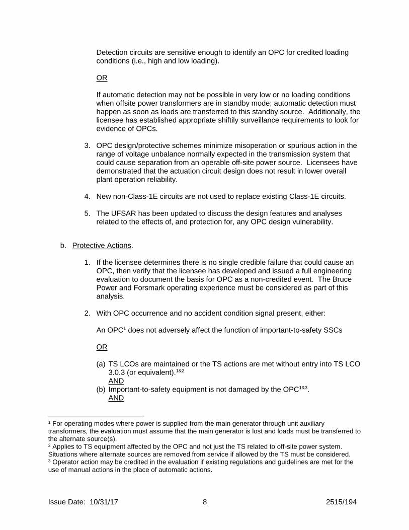
b. Protective Actions.
1. If the licensee determines there is no single credible failure that could cause an OPC, then verify that the licensee has developed and issued a full engineering evaluation to document the basis for OPC as a non-credited event. The Bruce Power and Forsmark operating experience must be considered as part of this analysis.
2. With OPC occurrence and no accident condition signal present, either:
An OPC1 does not adversely affect the function of important-to-safety SSCs OR (a) TS LCOs are maintained or the TS actions are met without entry into TS LCO
3.0.3 (or equivalent).1&2 AND
(b) Important-to-safety equipment is not damaged by the OPC1&3. AND
1 For operating modes where power is supplied from the main generator through unit auxiliary transformers, the evaluation must assume that the main generator is lost and loads must be transferred to the alternate source(s). 2 Applies to TS equipment affected by the OPC and not just the TS related to off-site power system. Situations where alternate sources are removed from service if allowed by the TS must be considered. 3 Operator action may be credited in the evaluation if existing regulations and guidelines are met for the use of manual actions in the place of automatic actions.
Issue Date: 10/31/17 9 2515/194
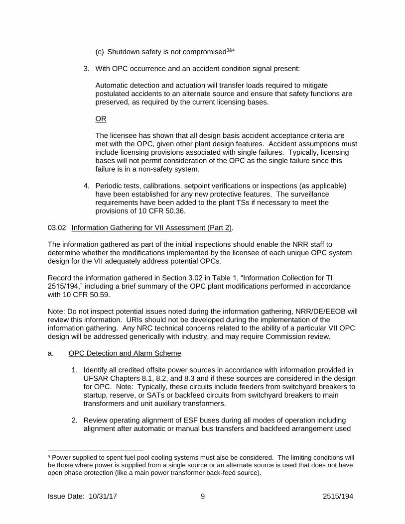
(c) Shutdown safety is not compromised3&4
3. With OPC occurrence and an accident condition signal present: Automatic detection and actuation will transfer loads required to mitigate postulated accidents to an alternate source and ensure that safety functions are preserved, as required by the current licensing bases. OR The licensee has shown that all design basis accident acceptance criteria are met with the OPC, given other plant design features. Accident assumptions must include licensing provisions associated with single failures. Typically, licensing bases will not permit consideration of the OPC as the single failure since this failure is in a non-safety system.
4. Periodic tests, calibrations, setpoint verifications or inspections (as applicable) have been established for any new protective features. The surveillance requirements have been added to the plant TSs if necessary to meet the provisions of 10 CFR 50.36.
03.02 Information Gathering for VII Assessment (Part 2). The information gathered as part of the initial inspections should enable the NRR staff to determine whether the modifications implemented by the licensee of each unique OPC system design for the VII adequately address potential OPCs. Record the information gathered in Section 3.02 in Table 1, “Information Collection for TI 2515/194,” including a brief summary of the OPC plant modifications performed in accordance with 10 CFR 50.59. Note: Do not inspect potential issues noted during the information gathering, NRR/DE/EEOB will review this information. URIs should not be developed during the implementation of the information gathering. Any NRC technical concerns related to the ability of a particular VII OPC design will be addressed generically with industry, and may require Commission review. a. OPC Detection and Alarm Scheme
1. Identify all credited offsite power sources in accordance with information provided in UFSAR Chapters 8.1, 8.2, and 8.3 and if these sources are considered in the design for OPC. Note: Typically, these circuits include feeders from switchyard breakers to startup, reserve, or SATs or backfeed circuits from switchyard breakers to main transformers and unit auxiliary transformers.
2. Review operating alignment of ESF buses during all modes of operation including
alignment after automatic or manual bus transfers and backfeed arrangement used
4 Power supplied to spent fuel pool cooling systems must also be considered. The limiting conditions will be those where power is supplied from a single source or an alternate source is used that does not have open phase protection (like a main power transformer back-feed source).

Issue Date: 10/31/17 10 2515/194
during plant shutdown. Identify if installed OPC detection scheme(s) monitor the paths to the ESF buses during all modes of operation.
3. Identify the scope of OPCs considered by the licensee. If the licensee has excluded certain OPCs (e.g., high voltage or low voltage side of power transformers), during operating and loading configurations in their analyses, identify the technical justifications for this exclusion.
4. Identify the capability of the detection schemes to detect OPCs under all operating electrical system configurations and plant loading conditions.
5. If the licensee has determined that OPC detection and alarm scheme is not needed at its facility because of specific design features such as oversized transformers or capability of existing undervoltage detection relay schemes, then identify the licensee’s calculational bases or test data that supports its basis as specified in the VII. Identify whether all OPCs are detected and alarmed in the Main Control Room (MCR) with the existing relays.
6. Identify if the detection and alarm circuits are independent of actuation (protection) circuits. Identify the safety classification of the detection and alarm circuits (safety or non-safety). If the detection, alarm and actuation circuits are non-Class 1E, identify if there is any interface with Class 1E systems.
7. Identify manufacturer provided data or information provided for the capability of installed VII relays to detect conditions, such as unbalanced voltage and current, negative sequence current, subharmonic current, or other parameters used to detect OPC in the offsite power system are appropriate. Identify the analyses and criteria used for the power system unbalance due to OPCs; and loading and operating configurations considered for all loading conditions such as standby, light load, worst-case accident and anticipated operational occurrences which involve plant trip followed by a bus transfer condition. If certain conditions cannot be detected, identify the licensee’s technical basis for its acceptability. Identify the functional testing done to validate limitations specified by the manufacturer of the relays.
8. Identify OPC detection circuit design features intended to minimize spurious operation due to voltage perturbations observed during events such as switching surges, transformer inrush currents, load or generation variations, and lightning strikes that are normally expected in the transmission system. Identify whether the licensee considered alarm/trip settings coordination with other electric power system relays including transmission system protection features to avoid false indications or unnecessary alarms.
9. Identify how the alarm features provided in the MCR including setpoints are maintained, calibrated, and controlled.
10. Identify if the presence of subharmonics in the power supply or offsite power system have been considered in the OPC detection scheme. Note: Power systems can be affected by the interaction of various components that can excite non-characteristic sub-harmonic frequencies i.e. below 60 Hertz power system frequency. Relays and detection schemes are susceptible to malfunctions or misoperations due to

Issue Date: 10/31/17 11 2515/194
subharmonics either in the source used to power the devices or in the power circuit that is being monitored.
11. Identify if OPC detection and alarm circuit components are scoped into the licensee’s
maintenance rule program. b. OPC Protection Scheme
1. Identify the location of the sensing of the protection scheme (high voltage or low voltage side of the transformer, ESF bus, etc.).
2. Identify the classification of the protection scheme, safety or non-safety. If a non-safety related system is used, identify any interface requirements with safety related systems.
3. Identify if the protection scheme is digital or non-digital and, if digital, identify applicable cyber security requirements considered in the design.
4. Identify any design features considered by the licensee to prevent protective
functional failures.
5. Identify the number of channels provided per offsite power source and if there is independence between channels and sensors.
6. Identify the power source used for the protection scheme and the consequences of
loss of power to the sensing/detection scheme.
7. Identify the consequences of a failure or malfunction of a channel.
8. Identify whether the design considered the single failure criteria as outlined in the GDCs or the principle design criteria specified in the updated final safety analysis report (i.e., for an OPC, a non-Class 1E circuit should not preclude the onsite electrical power system from being able to perform its safety function given a single failure of the onsite power system).
9. Identify the criteria that have been used by the licensee to verify power quality issues
caused by OPCs, such as unbalanced voltages and currents, sequence voltages and currents, phase angle shifts, and harmonic distortion that could adversely affect redundant ESF buses. Also, identify the industry standards used to develop the acceptance criteria.
10. Identify the analytical limits or criteria used for setpoints of the actuation/protection
scheme to provide adequate protection for motors and sensitive equipment at the plant.
11. Identify what design features have been considered in OPC protection features to
preclude spurious trips of the offsite power source (e.g. coincidence logic)?
12. Identify whether an analysis was performed by the licensee which demonstrates that the OPCs do not adversely affect the function(s) of important-to-safety equipment required for safe shutdown during anticipated operational occurrences and plant

Issue Date: 10/31/17 12 2515/194
operating configurations. If an analysis was not performed, identify the justification for which an analysis was not preformed. Note: This includes the licensee reviewing the bus transfer schemes and associated time delays, if any. The time delays associated with OPC detection scheme coupled with bus transfer time delays and time required for equipment to sequence and respond should be commensurate with time assumed in the accident analysis.
13. Identify if OPC protection/actuation circuit components are scoped, as appropriate,
into the licensee’s maintenance rule program. c. UFSAR Updates to Reflect the Need to Protect Against OPCs Using items 1 to 6 below as examples, identify whether the licensee has updated the
UFSAR (and supporting documents such as calculations of record, design change modifications, etc.) to ensure plant-specific licensing basis/requirements include discussions of the design features and analyses related to the effects of, and protection for, any open phase condition design vulnerability:
1. Identify whether the licensee has documented the plant-specific analysis and
documentation that established the resolution of the OPC design vulnerability, including the failure mode analysis performed.
2. Identify whether the licensee has a description of their OPC automatic detection scheme, including how offsite power system OPCs are detected from sensing to alarm devices (loss of one or two phases of the three phases of the offsite power circuit both with and without a high-impedance ground fault condition on the high-voltage side of all credited qualified offsite power sources under all loading and operating configurations; and loss of one or two phases of three phases of switchyard breakers that feed offsite power circuits to transformers without ground.
3. Identify whether the licensee has documented detection circuit design features to minimize spurious indications for an operable offsite power source in the range of voltage perturbations, such as switching surges, transformer inrush currents, load or generation variations, and lightning strikes, normally expected in the transmission system.
4. Identify whether the licensee has documented alarm features provided in the MCR. Discuss the ESF bus alignment during normal plant operation and the operating procedures in place to address OPCs. If the plant auxiliaries are supplied from the main generator and the offsite power circuit to the ESF bus is configured as a standby power source, then OPCs should be alarmed in the MCR for operators to take corrective action within a reasonable time.
5. Identify whether the licensee has documented the automatic protection scheme provided for OPCs including applicable industry standards used for designing the scheme. In addition, design features to minimize spurious actuations for an operable offsite power source in the range of voltage perturbations, such as switching surges, transformer inrush currents, load or generation variations, and lightning strikes, normally expected in the transmission system should be described.

Issue Date: 10/31/17 13 2515/194
6. Identify that the licensee has a brief discussion of the analyses performed for accident condition concurrent OPCs which demonstrate that the actuation scheme will transfer ESF loads required to mitigate postulated accidents to an alternate source consistent with accident analyses assumptions to ensure that safety functions are preserved, as required by the licensing bases.
d. Technical Specifications Surveillance Requirements and Limiting Condition of Operation
(LCO) for Equipment Used for OPC Mitigation
Identify if TSs Surveillance Requirements (SRs) and LCO for equipment used for mitigation of OPC is identified and implemented consistent with the operability requirements specified in the plant TSs. If the licensee determines that TSs are not affected, document the licensee’s basis. If SRs and LCOs are being addressed by licensee-controlled programs, such as Technical Requirements Manual, describe the testing and operational limitations associated with this equipment, if applicable.
2515/194-04 REPORTING AND DOCUMENTATION REQUIREMENTS Document the completion of this TI in the integrated quarterly report or in a standalone inspection report. Attach the collected information in Table 1 of this TI to the inspection report, document the VII inspection activity along with any issues identified during the inspection of the VII as URIs. Any URIs associated with this TI will be subsequently examined by a review panel and dispositioned in a subsequent report (as appropriate). 2515/192-05 COMPLETION SCHEDULE This TI is to be completed by December 31, 2019. 2515/192-06 EXPIRATION The TI will expire on December 30, 2020. 2515/192-07 CONTACT Any technical questions regarding this TI shall be sent electronically to OPC TI 2515-194-08 ([email protected]). This email resource will be monitored by NRR/DE/EEOB staff. Any Reactor Oversight Process-related questions shall be addressed to Stephen Campbell at (301) 415-3353 or Christopher Cauffman, at (301) 415-8416. Questions can also be sent electronically to [email protected] or [email protected]. 2515/194-08 STATISTICAL DATA REPORTING Charge all direct inspection and information collection efforts to TI 2515/194 using IPE code TI. Charge all preparation and documentation time to activity code TPD (CAC 000989).

Issue Date: 10/31/17 14 2515/194
2515/194-09 RESOURCE ESTIMATE Estimated time to complete this TI is 50-60 hours per site for direct inspection and information collection efforts and 24-32 hours for preparation and documentation. 2515/194-10 TRAINING It is expected that this inspection will be performed by the regional electrical engineering specialist or contractors who are knowledgeable in electrical power system design and analyses for nuclear power reactors. However, specialized brief training on the OPCs will be provided by NRR/DE/EEOB staff prior to implementation of this TI. 2515/194-11 REFERENCES IP 71152, “Problem Identification and Resolution” IP 71111.17T, “Evaluations of Changes, Tests and Experiments” IP 71111.18, “Plant Modifications”
IP 71111.21M, “Design Bases Assurance Inspection (Teams)”
END

Issue Date: 10/31/17 T1-1 2515/194
Table 1 – Information Gathered for TI 2515/194
A OPC Detection and Alarm Scheme
Describe Observations/Comments
1 Are all credited offsite power sources specified in UFSAR Chapters 8.1, 8.2, and 8.3 and plant TSs considered in the design of OPC detection and protection schemes?
Yes No
2 Are OPC detection scheme(s) installed to monitor the qualified offsite power paths to the ESF buses during all modes of operation?
Yes No
3 What is the scope of OPCs considered by the licensee? Did the licensee excluded certain OPCs (e.g., high voltage or low voltage side of power transformers), operating and loading configurations in their analyses? If so, identify the technical justifications for any exclusion.
Yes No
4 Are the detection schemes capable to identify OPCs under all operating electrical system configurations and plant loading conditions?
Yes No
5 If the licensee determined that OPC detection and alarm scheme was not needed, did the licensee provide adequate calculational bases or test data? Are all OPCs detected and alarmed in the MCR with the existing relays?
Yes No
Yes No
6 Are the detection and alarm circuits independent of actuation (protection) circuits?
Yes No

Issue Date: 10/31/17 T1-2 2515/194
If the detection, alarm and actuation circuits are non-Class 1E, was there any interface with Class 1E systems?
Yes No
7 Did the manufacturer provide any information/data for the capability of installed relays to detect conditions, such as unbalanced voltage and current, negative sequence current, subharmonic current or other parameters used to detect OPC in the offsite power system? What are the analyses and criteria used by the licensee to identify the power system unbalance due to OPCs; and loading and operating configurations considered for all loading conditions which involve plant trip followed by bus transfer condition? If certain conditions cannot be detected, did the licensee document the technical basis for its acceptability? Did the licensee perform functional testing to validate limitations specified by the manufacturer of the relays?
Yes No
Yes No
Yes No
8 Do OPC detection circuit design features minimize spurious detections due to voltage perturbations observed during events which are normally expected in the transmission system? Identify whether the licensee considered alarm/trip settings coordination with other electric power system relays including
Yes No
Issue Date: 10/31/17 T1-3 2515/194
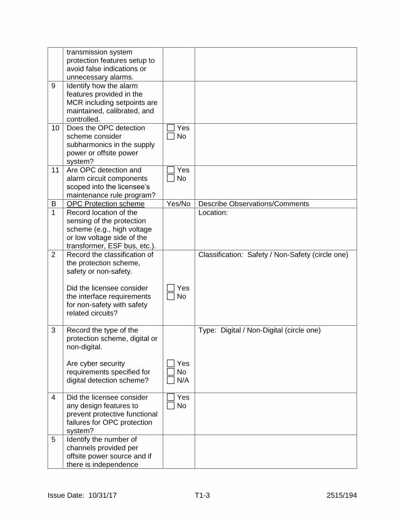
transmission system protection features setup to avoid false indications or unnecessary alarms.
9 Identify how the alarm features provided in the MCR including setpoints are maintained, calibrated, and controlled.
10 Does the OPC detection scheme consider subharmonics in the supply power or offsite power system?
Yes No
11 Are OPC detection and alarm circuit components scoped into the licensee’s maintenance rule program?
Yes No
B OPC Protection scheme Yes/No Describe Observations/Comments
1 Record location of the sensing of the protection scheme (e.g., high voltage or low voltage side of the transformer, ESF bus, etc.).
Location:
2 Record the classification of the protection scheme, safety or non-safety. Did the licensee consider the interface requirements for non-safety with safety related circuits?
Yes No
Classification: Safety / Non-Safety (circle one)
3 Record the type of the protection scheme, digital or non-digital. Are cyber security requirements specified for digital detection scheme?
Yes No N/A
Type: Digital / Non-Digital (circle one)
4 Did the licensee consider any design features to prevent protective functional failures for OPC protection system?
Yes No
5 Identify the number of channels provided per offsite power source and if there is independence

Issue Date: 10/31/17 T1-4 2515/194
between channels and sensors.
6 What is the safety classification of power supply for the protection scheme? Was a loss of power to the protection scheme considered?
Yes No
7 Identify if the licensee considered the consequences of a failure or malfunction of a channel.
8 Did the design consider the single failure criteria as outlined in the GDCs or the principle design criteria specified in the updated final safety analysis report?
Yes No
9 Did the licensee identify the industry standards and criteria to verify power quality issues caused by OPCs that affect redundant ESF buses? What industry standards were used to develop the acceptance criteria for OPC trip setpoint or analytical limit?
Yes No
10 What are the analytical limits or criteria used for setpoints of the actuation/protection scheme to provide adequate protection for motors and sensitive equipment?
11 What are the design features provided to preclude spurious trips of the offsite power source (e.g. coincidence logic)?
12 What analyses have been performed by the licensee which demonstrates that the OPCs do not adversely affect the function(s) of important-to-safety

Issue Date: 10/31/17 T1-5 2515/194
equipment required for safe shutdown during anticipated operational occurrences, design basis events, and accidents? If an analyses was not performed, what justification was provided? Are bus transfer schemes and associated time delays considered?
Yes No
13 Are OPC protection/actuation circuit components scoped, as appropriate, into the licensee’s maintenance rule program?
Yes No
C UFSAR Updates to Reflect the Need to Protect Against OPCs: Using items 1 to 6 below as examples, identify whether the licensee has updated the UFSAR (and supporting documents such as calculations of record, design change modifications, etc.) to ensure plant-specific licensing basis/requirements include discussions of the design features and analyses related to the effects of, and protection for, any open phase condition design vulnerability:
Yes/No Describe Observations/Comments
1 The plant-specific analysis and documentation that established the resolution of the OPC design vulnerability, including the failure mode analysis performed.
2 Description of OPC automatic detection scheme, including how offsite power system OPCs are detected from sensing to alarm devices (loss of one or two phases of the three phases

Issue Date: 10/31/17 T1-6 2515/194
of the offsite power circuit both with and without a high-impedance ground fault condition on the high-voltage side of all credited qualified offsite power sources under all loading and operating configurations; and loss of one or two phases of three phases of switchyard breakers that feed offsite power circuits to transformers without ground.
3 Detection circuit design features to minimize spurious indications for an operable offsite power source in the range of voltage perturbations, such as switching surges, transformer inrush currents, load or generation variations, and lightning strikes, normally expected in the transmission system.
4 Alarm features provided in the MCR. Discuss the ESF bus alignment during normal plant operation and the operating procedures in place to address OPCs. If the plant auxiliaries are supplied from the main generator and the offsite power circuit to the ESF bus is configured as a standby power source, then OPCs should be alarmed in the MCR for operators to take corrective action within a reasonable time.
5 Describe the automatic protection scheme provided for OPCs including applicable industry standards used for designing the scheme. Design features to minimize spurious actuations for an operable offsite power
Issue Date: 10/31/17 T1-7 2515/194
source in the range of voltage perturbations, such as switching surges, transformer inrush currents, load or generation variations, and lightning strikes, normally expected in the transmission system should be described.
6 Brief discussion of the licensee’s analyses performed for accident condition concurrent OPCs which demonstrate that the actuation scheme will transfer ESF loads required to mitigate postulated accidents to an alternate source consistent with accident analyses assumptions to ensure that safety functions are preserved, as required by the licensing bases.
D TS Surveillance Requirements and LCO for Equipment Used for OPC Mitigation
Describe Observations/Comments
1 Are TSs Surveillance Requirements and LCO for equipment used for the mitigation of OPC identified and implemented consistent with the operability requirements specified in the plant TSs? If the licensee determined that TSs are unaffected because OPC is being addressed by licensee-controlled programs, is the technical justification adequate?
Yes No
Yes No
E
Provide a brief summary of the OPC plant modification performed under 10 CFR 50.59.

Issue Date: 10/31/17 Att1-1 2515/194
Attachment 1 – Revision History for TI 2515/194
Commitment Tracking Number
Accession Number
Issue Date Change Notice
Description of Change Description of Training Required and Completion Date
Comment Resolution and Closed Feedback Form Accession Number (Pre-Decisional, Non-Public Information)
ML17220A253 DRAFT CN 17-XXX
Draft version of the TI was made public to share with industry during a public meeting held on August 15, 2017.
n/a ML17158B437
ML17137A416 10/31/2017 CN 17-024
Initial issuance. Researched commitments for the last four years and found none. This Temporary Instruction (TI) applies to the holders of operating licenses for operating nuclear power reactors who have implemented actions to protect against open phase conditions (OPCs). This TI is to be performed at all current operating plants with the exception of Seabrook Station, Unit 1, plants seeking NRC approval in accordance with 10 CFR 50.90, and sites that have informed the NRC of their intent to decommission prior to 01/30/2020. CA Note: Initiation of Temporary Instruction 2515/194 To Inspect Implementation of Industry Initiative Associated With Open Phase Condition Design Vulnerabilities In Electric Power Systems ML17240A034
It is expected that this inspection will be performed by the regional electrical engineering specialist or contractors who are knowledgeable in electrical power system design and analyses for nuclear power reactors. However, a specialized brief training on the OPCs will be provided by NRR/DE/EEOB staff prior to 10/31/17.
ML17158B437