november 2019 rosemount 5900 - emerson electric · nut m8 spring washer washer nut m8 m8 terminal...
TRANSCRIPT
Manual Supplement00809-0200-5900, Rev AC
November 2019
Rosemount™ 5900Instruction for Installation, Configuration, and Operation of Proof Test Function with Reference Reflector

Manual Supplement00809-0200-5900, Rev AC
ContentsNovember 2019
Contents
1Section 1: Introduction1.1 Section overview . . . . . . . . . . . . . . . . . . . . . . . . . . . . . . . . . . . . . . . . . . . . . . . . . . . . . . . 2
1.2 Service support. . . . . . . . . . . . . . . . . . . . . . . . . . . . . . . . . . . . . . . . . . . . . . . . . . . . . . . . . 2
1.3 Installation procedure . . . . . . . . . . . . . . . . . . . . . . . . . . . . . . . . . . . . . . . . . . . . . . . . . . . 3
2Section 2: Installation2.1 Overview . . . . . . . . . . . . . . . . . . . . . . . . . . . . . . . . . . . . . . . . . . . . . . . . . . . . . . . . . . . . . . 5
2.2 Safety messages . . . . . . . . . . . . . . . . . . . . . . . . . . . . . . . . . . . . . . . . . . . . . . . . . . . . . . . . 5
2.3 Installation considerations . . . . . . . . . . . . . . . . . . . . . . . . . . . . . . . . . . . . . . . . . . . . . . . 6
2.4 Installing the Reference Reflector for Parabolic Antenna . . . . . . . . . . . . . . . . . . . . . 7
2.4.1 Reference Reflector Kit . . . . . . . . . . . . . . . . . . . . . . . . . . . . . . . . . . . . . . . . . . . . 7
2.4.2 Tank Geometry - Parabolic Antenna . . . . . . . . . . . . . . . . . . . . . . . . . . . . . . . . . 9
2.4.3 Installing the Reference Reflector . . . . . . . . . . . . . . . . . . . . . . . . . . . . . . . . . .11
2.5 Installing the Reference Reflector for Array Antenna . . . . . . . . . . . . . . . . . . . . . . .18
2.5.1 Reference Reflector Kit . . . . . . . . . . . . . . . . . . . . . . . . . . . . . . . . . . . . . . . . . . .18
2.5.2 Tank Geometry - Array Antenna. . . . . . . . . . . . . . . . . . . . . . . . . . . . . . . . . . . .20
2.5.3 Installing the Reference Reflector . . . . . . . . . . . . . . . . . . . . . . . . . . . . . . . . . .23
3Section 3: Configuration of Reference Reflector3.1 Overview . . . . . . . . . . . . . . . . . . . . . . . . . . . . . . . . . . . . . . . . . . . . . . . . . . . . . . . . . . . . .29
3.2 Safety messages . . . . . . . . . . . . . . . . . . . . . . . . . . . . . . . . . . . . . . . . . . . . . . . . . . . . . . .29
3.3 Configuration using TankMaster WinSetup . . . . . . . . . . . . . . . . . . . . . . . . . . . . . . .30
3.3.1 Introduction. . . . . . . . . . . . . . . . . . . . . . . . . . . . . . . . . . . . . . . . . . . . . . . . . . . . .30
3.3.2 Considerations . . . . . . . . . . . . . . . . . . . . . . . . . . . . . . . . . . . . . . . . . . . . . . . . . .30
3.3.3 Configuration procedure. . . . . . . . . . . . . . . . . . . . . . . . . . . . . . . . . . . . . . . . . .31
iContents
Manual Supplement00809-0200-5900, Rev AC
ContentsNovember 2019
4Section 4: Operation4.1 Overview . . . . . . . . . . . . . . . . . . . . . . . . . . . . . . . . . . . . . . . . . . . . . . . . . . . . . . . . . . . . .39
4.2 Safety messages . . . . . . . . . . . . . . . . . . . . . . . . . . . . . . . . . . . . . . . . . . . . . . . . . . . . . . .39
4.3 Proof Test operation . . . . . . . . . . . . . . . . . . . . . . . . . . . . . . . . . . . . . . . . . . . . . . . . . . .40
4.3.1 Proof Test status . . . . . . . . . . . . . . . . . . . . . . . . . . . . . . . . . . . . . . . . . . . . . . . . .43
4.4 Scheduling. . . . . . . . . . . . . . . . . . . . . . . . . . . . . . . . . . . . . . . . . . . . . . . . . . . . . . . . . . . .44
4.4.1 Pop-up message . . . . . . . . . . . . . . . . . . . . . . . . . . . . . . . . . . . . . . . . . . . . . . . . .45
4.5 History . . . . . . . . . . . . . . . . . . . . . . . . . . . . . . . . . . . . . . . . . . . . . . . . . . . . . . . . . . . . . . .46
4.6 Reports. . . . . . . . . . . . . . . . . . . . . . . . . . . . . . . . . . . . . . . . . . . . . . . . . . . . . . . . . . . . . . .47
4.6.1 Viewing a report . . . . . . . . . . . . . . . . . . . . . . . . . . . . . . . . . . . . . . . . . . . . . . . . .48
4.7 Removing a Reference Reflector . . . . . . . . . . . . . . . . . . . . . . . . . . . . . . . . . . . . . . . . .50
5Section 5: Service and Troubleshooting5.1 Safety messages . . . . . . . . . . . . . . . . . . . . . . . . . . . . . . . . . . . . . . . . . . . . . . . . . . . . . . .51
5.2 Troubleshooting. . . . . . . . . . . . . . . . . . . . . . . . . . . . . . . . . . . . . . . . . . . . . . . . . . . . . . .52
5.3 Tank spectrum . . . . . . . . . . . . . . . . . . . . . . . . . . . . . . . . . . . . . . . . . . . . . . . . . . . . . . . .53
ii Contents
Manual Supplement00809-0200-5900, Rev AC
Section 1: IntroductionNovember 2019
Section 1 Introduction
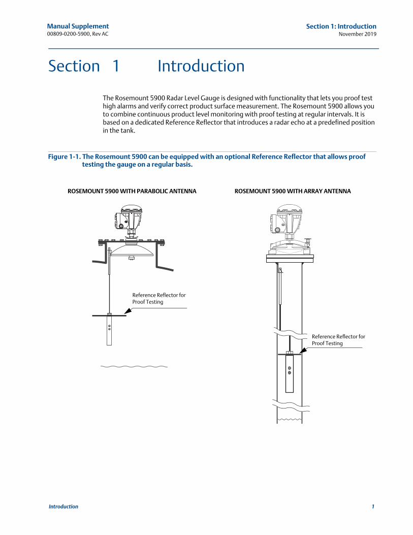
The Rosemount 5900 Radar Level Gauge is designed with functionality that lets you proof test high alarms and verify correct product surface measurement. The Rosemount 5900 allows you to combine continuous product level monitoring with proof testing at regular intervals. It is based on a dedicated Reference Reflector that introduces a radar echo at a predefined position in the tank.
Figure 1-1. The Rosemount 5900 can be equipped with an optional Reference Reflector that allows proof testing the gauge on a regular basis.
Reference Reflector for Proof Testing
Reference Reflector for Proof Testing
ROSEMOUNT 5900 WITH PARABOLIC ANTENNA ROSEMOUNT 5900 WITH ARRAY ANTENNA
1Introduction
Manual Supplement00809-0200-5900, Rev AC
Section 1: IntroductionNovember 2019
1.1 Section overview
This document is a supplement to the Rosemount 5900S Reference Manual (Document No. 00809-0100-5900).
The sections in this reference manual supplement provide information on installing, operating, and maintaining the Rosemount 5900 Proof Test System. The sections are organized as follows:
Section 1: Introduction gives a brief introduction to the Rosemount 5900 Proof Test function and the recommended installation procedure.
Section 2: Installation provides instructions on how to install the Reference Reflector on the Rosemount 5900 with Parabolic Antenna and Array Antenna.
Section 3: Configuration contains instructions on how to calibrate and configure the Rosemount 5900 Proof Test function.
Section 4: Operation provides instructions for how to use the proof test function.
Section 5: Service and Troubleshooting provides troubleshooting techniques for the most common operating problems.
1.2 Service support
For service support contact the nearest Emerson Process Management/Rosemount Tank Gauging representative. Contact information can be found on the web site www.Emerson.com.
2 Introduction
Manual Supplement00809-0200-5900, Rev AC
Section 1: IntroductionNovember 2019
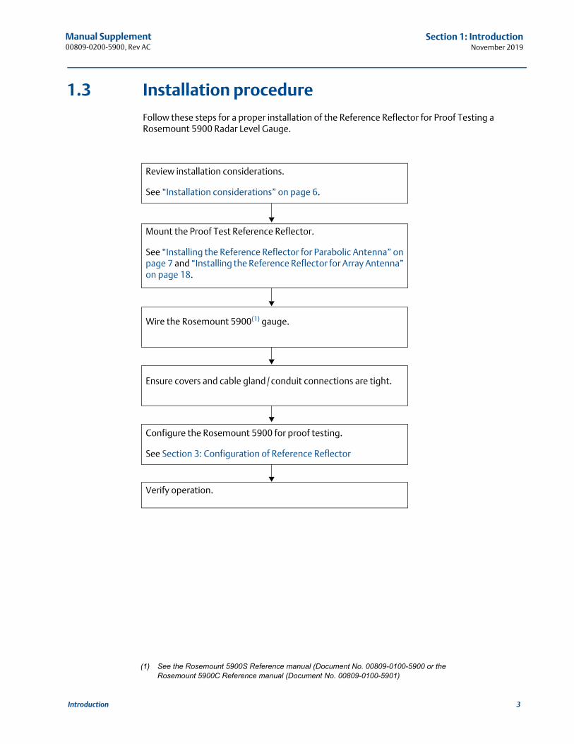
1.3 Installation procedure
Follow these steps for a proper installation of the Reference Reflector for Proof Testing a Rosemount 5900 Radar Level Gauge.
Review installation considerations.
See “Installation considerations” on page 6.
Mount the Proof Test Reference Reflector.
See “Installing the Reference Reflector for Parabolic Antenna” on page 7 and “Installing the Reference Reflector for Array Antenna” on page 18.
Wire the Rosemount 5900(1) gauge.
Ensure covers and cable gland /conduit connections are tight.
Configure the Rosemount 5900 for proof testing.
See Section 3: Configuration of Reference Reflector
Verify operation.
(1) See the Rosemount 5900S Reference manual (Document No. 00809-0100-5900 or the Rosemount 5900C Reference manual (Document No. 00809-0100-5901)
Introduction
3
Manual Supplement00809-0200-5900, Rev AC
Section 1: IntroductionNovember 2019
4 Introduction
Manual Supplement00809-0200-5900, Rev AC
Section 2: InstallationNovember 2019
Section 2 Installation
Overview . . . . . . . . . . . . . . . . . . . . . . . . . . . . . . . . . . . . . . . . . . . . . . . . . . . . . . . . . . . . . . . . . . page 5Safety messages . . . . . . . . . . . . . . . . . . . . . . . . . . . . . . . . . . . . . . . . . . . . . . . . . . . . . . . . . . . . page 5Installation considerations . . . . . . . . . . . . . . . . . . . . . . . . . . . . . . . . . . . . . . . . . . . . . . . . . . . page 6Installing the Reference Reflector for Parabolic Antenna . . . . . . . . . . . . . . . . . . . . . . . . . page 7Installing the Reference Reflector for Array Antenna . . . . . . . . . . . . . . . . . . . . . . . . . . . . . page 18
2.1 Overview
The information in this section covers installation of Reference Reflector for proof testing the Rosemount 5900 Radar Level Gauge.
2.2 Safety messages
Procedures and instructions in this section may require special precautions to ensure the safety of the personnel performing the operation. Information that raises potential safety issues is indicated by a warning symbol ( ). Refer to the following safety messages before performing an operation preceded by this symbol.
Failure to follow safe installation and servicing guidelines could result in death or serious injury:
Make sure only qualified personnel perform the installation.
Use the equipment only as specified in this manual. Failure to do so may impair the protection provided by the equipment.
Do not perform any service other than those contained in this manual unless you are qualified.
High voltage that may be present on leads could cause electrical shock:
Avoid contact with leads and terminals.
Make sure the main power to the 2460 System Hub is off and the lines to any other external power source are disconnected or not powered while wiring the 2460.
Electrical shock could cause death or serious injury:
Use extreme caution when making contact with the leads and terminals.
Handle the wire and assembly with care to avoid permanent bends.
5Installation
Manual Supplement00809-0200-5900, Rev AC
Section 2: InstallationNovember 2019
2.3 Installation considerations
Before you start installing the Reference Reflector, ensure that the following items are considered in order to fulfill the installation requirements for the Reference Reflector at the desired position:
Maximum product level in the tank
High Alarm position
Minimum / maximum distance between Gauge Reference Point and Reference Reflector
See “Tank Geometry - Parabolic Antenna” on page 9 and “Tank Geometry - Array Antenna” on page 20 for further information on tank geometry and position of the Reference Reflector.
NoteThe Reference Reflector for Array Antenna may need to be removed to allow product sampling through the Still-pipe.
6 Installation
Manual Supplement00809-0200-5900, Rev AC
Section 2: InstallationNovember 2019
2.4 Installing the Reference Reflector for Parabolic Antenna
The Reference Reflector is installed under the antenna. It is attached to a wire fixed to the Parabolic Antenna. The Reference Reflector introduces a radar echo that is used for proof testing the Rosemount 5900 Radar Level Gauge. Proof testing can be performed without the need to open the tank.
2.4.1 Reference Reflector Kit
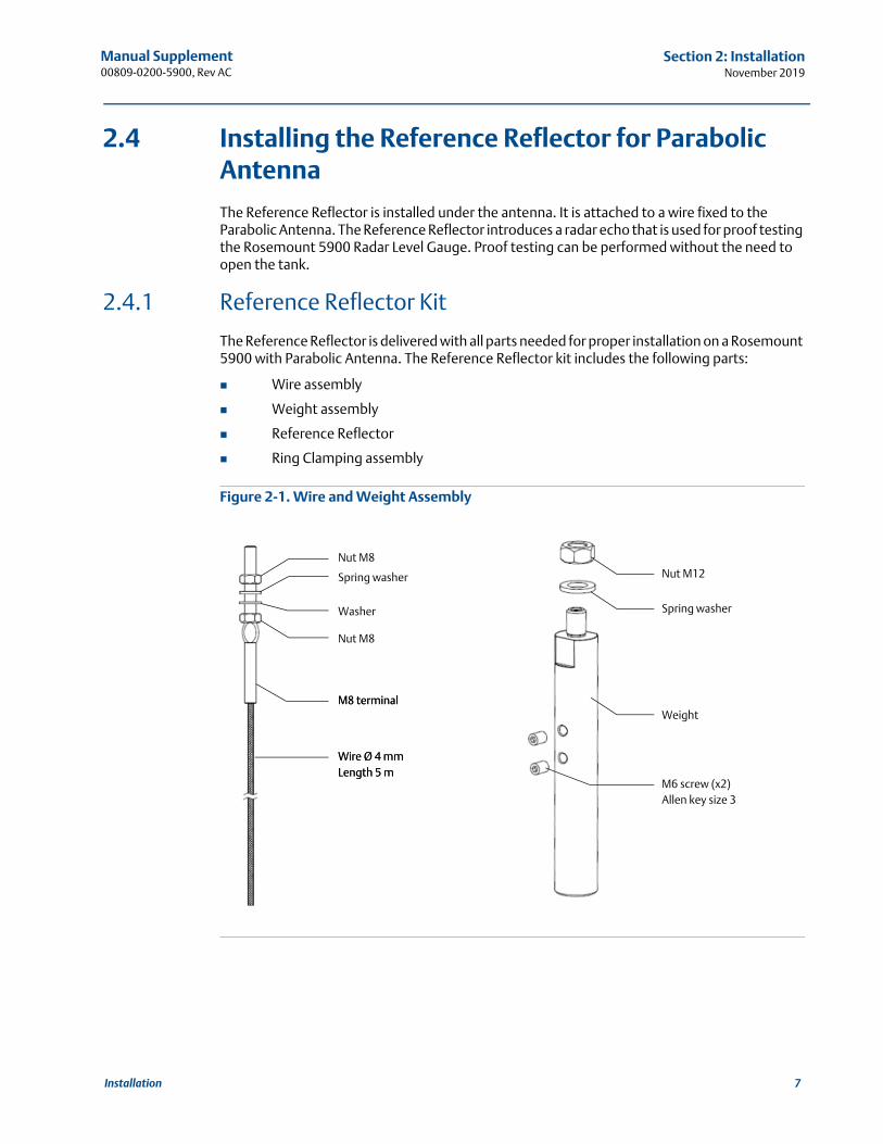
The Reference Reflector is delivered with all parts needed for proper installation on a Rosemount 5900 with Parabolic Antenna. The Reference Reflector kit includes the following parts:
Wire assembly
Weight assembly
Reference Reflector
Ring Clamping assembly
Figure 2-1. Wire and Weight Assembly
Nut M8
Spring washer
Washer
Nut M8
M8 terminal
Wire Ø 4 mmLength 5 mWire Ø 4 mmLength 5 m
M8 terminal
Nut M12
Spring washer
Weight
M6 screw (x2)Allen key size 3
7Installation
Manual Supplement00809-0200-5900, Rev AC
Section 2: InstallationNovember 2019
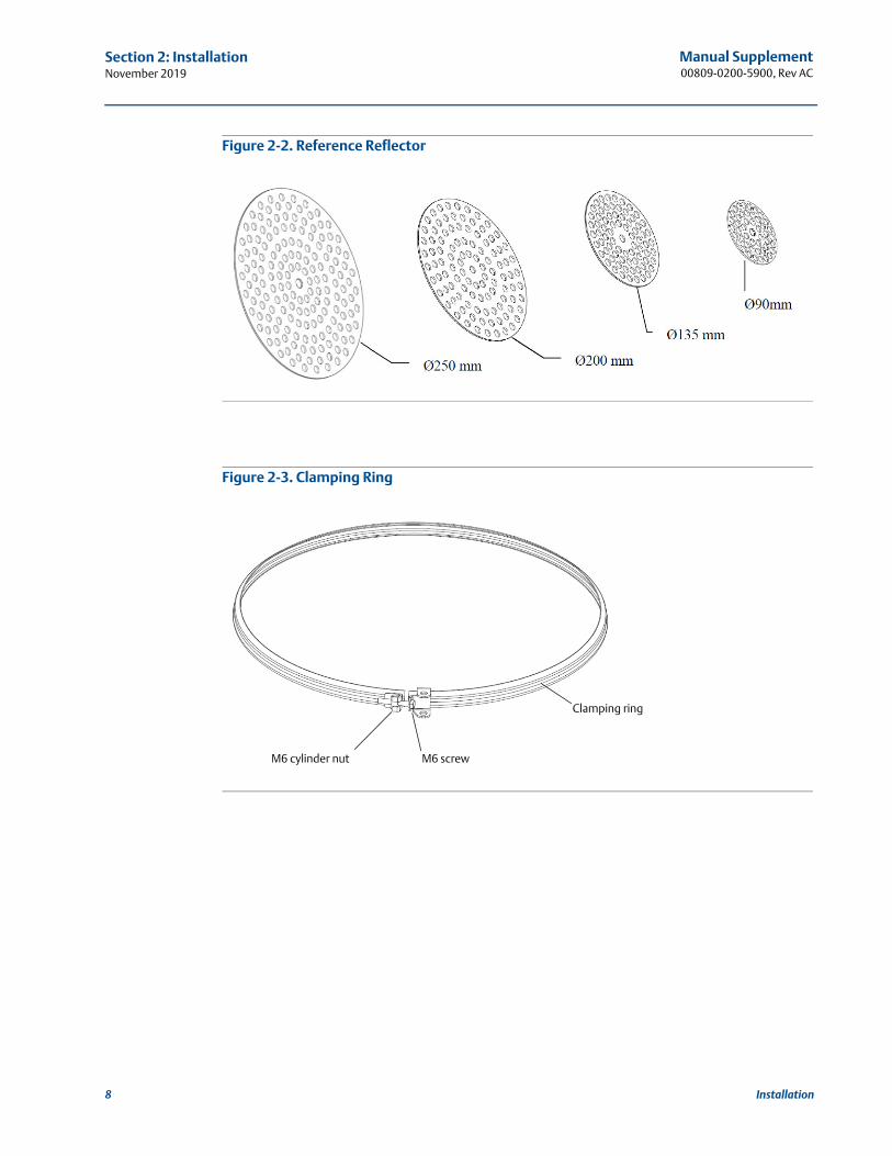
Figure 2-2. Reference Reflector
Figure 2-3. Clamping Ring
M6 cylinder nut M6 screw
Clamping ring
8 Installation
Manual Supplement00809-0200-5900, Rev AC
Section 2: InstallationNovember 2019
2.4.2 Tank Geometry - Parabolic Antenna
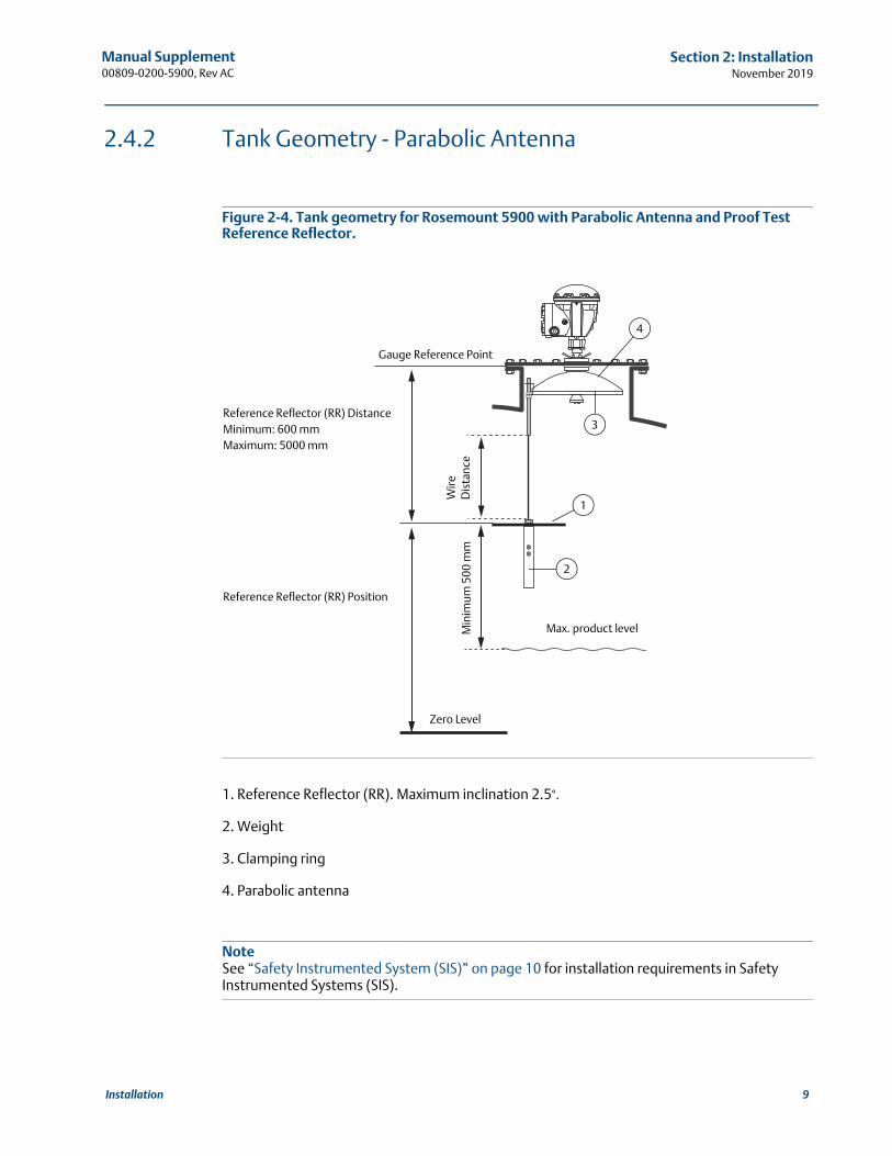
Figure 2-4. Tank geometry for Rosemount 5900 with Parabolic Antenna and Proof Test Reference Reflector.
1. Reference Reflector (RR). Maximum inclination 2.5°.
2. Weight
3. Clamping ring
4. Parabolic antenna
NoteSee “Safety Instrumented System (SIS)” on page 10 for installation requirements in Safety Instrumented Systems (SIS).
Wire
Dis
tanc
e
Reference Reflector (RR) DistanceMinimum: 600 mmMaximum: 5000 mm
Reference Reflector (RR) Position
Min
imum
500
mm
3
4
1
2
Zero Level
Max. product level
Gauge Reference Point
9Installation
Manual Supplement00809-0200-5900, Rev AC
Section 2: InstallationNovember 2019
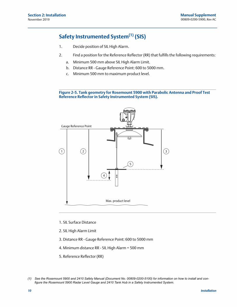
Safety Instrumented System(1) (SIS)
1. Decide position of SIL High Alarm.
2. Find a position for the Reference Reflector (RR) that fulfills the following requirements:
a. Minimum 500 mm above SIL High Alarm Limit.
b. Distance RR - Gauge Reference Point: 600 to 5000 mm.
c. Minimum 500 mm to maximum product level.
Figure 2-5. Tank geometry for Rosemount 5900 with Parabolic Antenna and Proof Test Reference Reflector in Safety Instrumented System (SIS).
1. SIL Surface Distance
2. SIL High Alarm Limit
3. Distance RR - Gauge Reference Point: 600 to 5000 mm
4. Minimum distance RR - SIL High Alarm = 500 mm
5. Reference Reflector (RR)
(1) See the Rosemount 5900 and 2410 Safety Manual (Document No. 00809-0200-5100) for information on how to install and con-figure the Rosemount 5900 Radar Level Gauge and 2410 Tank Hub in a Safety Instrumented System.
4
21
Max. product level
Gauge Reference Point
3
5
10 Installation
Manual Supplement00809-0200-5900, Rev AC
Section 2: InstallationNovember 2019
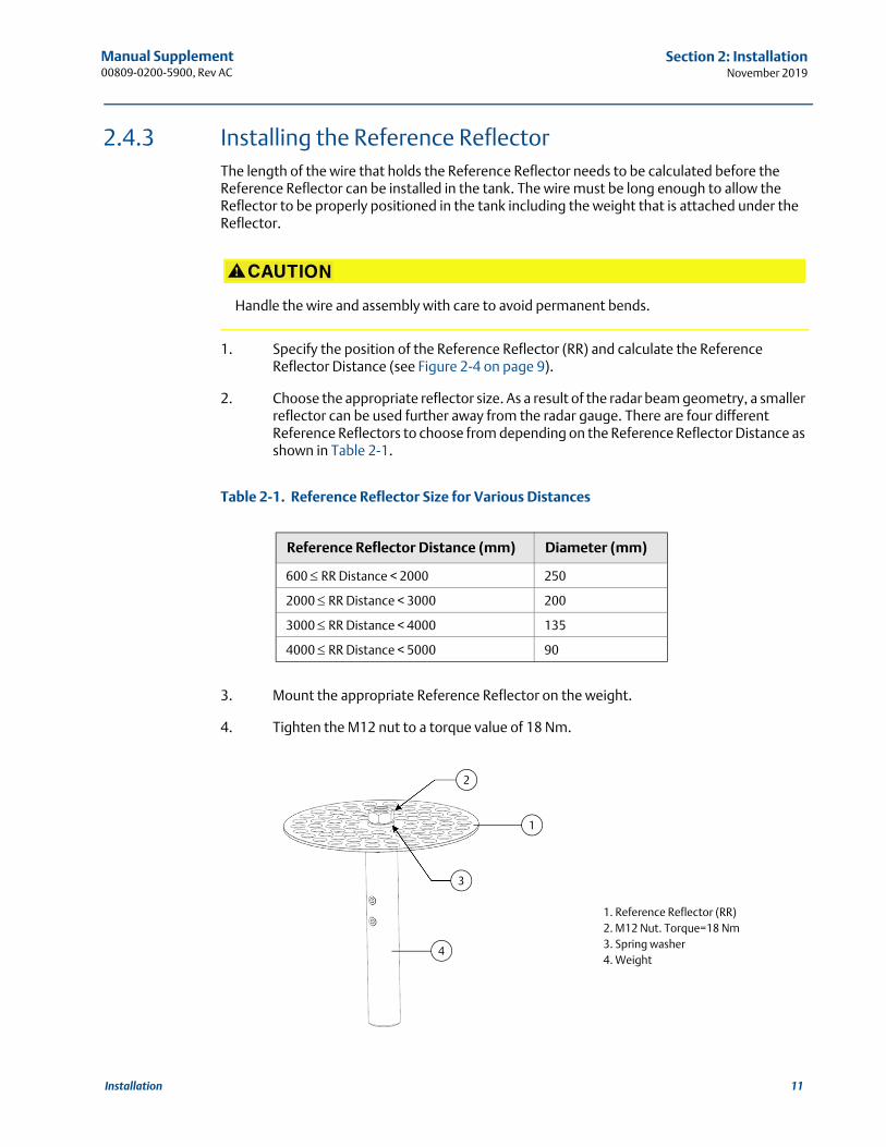
2.4.3 Installing the Reference ReflectorThe length of the wire that holds the Reference Reflector needs to be calculated before the Reference Reflector can be installed in the tank. The wire must be long enough to allow the Reflector to be properly positioned in the tank including the weight that is attached under the Reflector.
1. Specify the position of the Reference Reflector (RR) and calculate the Reference Reflector Distance (see Figure 2-4 on page 9).
2. Choose the appropriate reflector size. As a result of the radar beam geometry, a smaller reflector can be used further away from the radar gauge. There are four different Reference Reflectors to choose from depending on the Reference Reflector Distance as shown in Table 2-1.
Table 2-1. Reference Reflector Size for Various Distances
3. Mount the appropriate Reference Reflector on the weight.
4. Tighten the M12 nut to a torque value of 18 Nm.
Handle the wire and assembly with care to avoid permanent bends.
Reference Reflector Distance (mm) Diameter (mm)
600 RR Distance < 2000 250
2000 RR Distance < 3000 200
3000 RR Distance < 4000 135
4000 RR Distance < 5000 90
1
4
1. Reference Reflector (RR)2. M12 Nut. Torque=18 Nm3. Spring washer4. Weight
3
2
11Installation
Manual Supplement00809-0200-5900, Rev AC
Section 2: InstallationNovember 2019
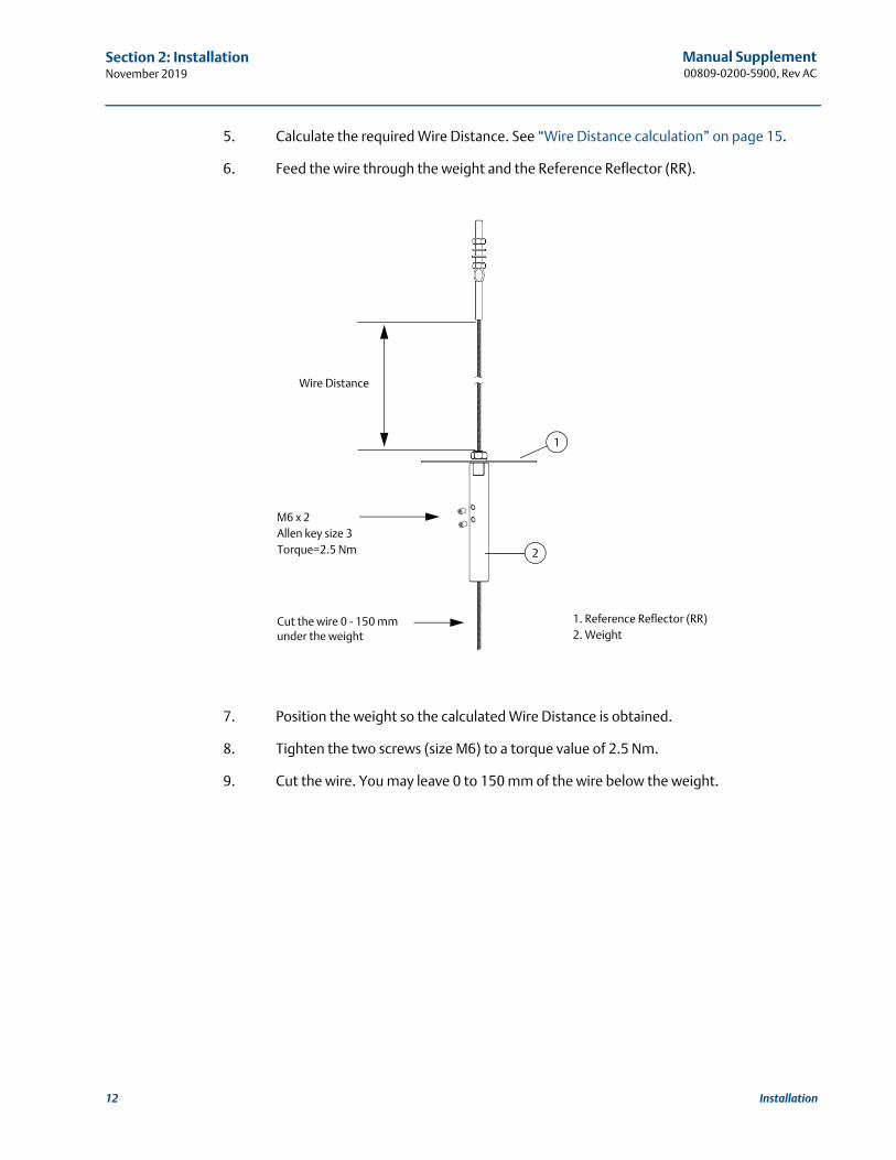
5. Calculate the required Wire Distance. See “Wire Distance calculation” on page 15.
6. Feed the wire through the weight and the Reference Reflector (RR).
7. Position the weight so the calculated Wire Distance is obtained.
8. Tighten the two screws (size M6) to a torque value of 2.5 Nm.
9. Cut the wire. You may leave 0 to 150 mm of the wire below the weight.
1
2
Wire Distance
1. Reference Reflector (RR)2. Weight
M6 x 2Allen key size 3Torque=2.5 Nm
Cut the wire 0 - 150 mm under the weight
12 Installation
Manual Supplement00809-0200-5900, Rev AC
Section 2: InstallationNovember 2019
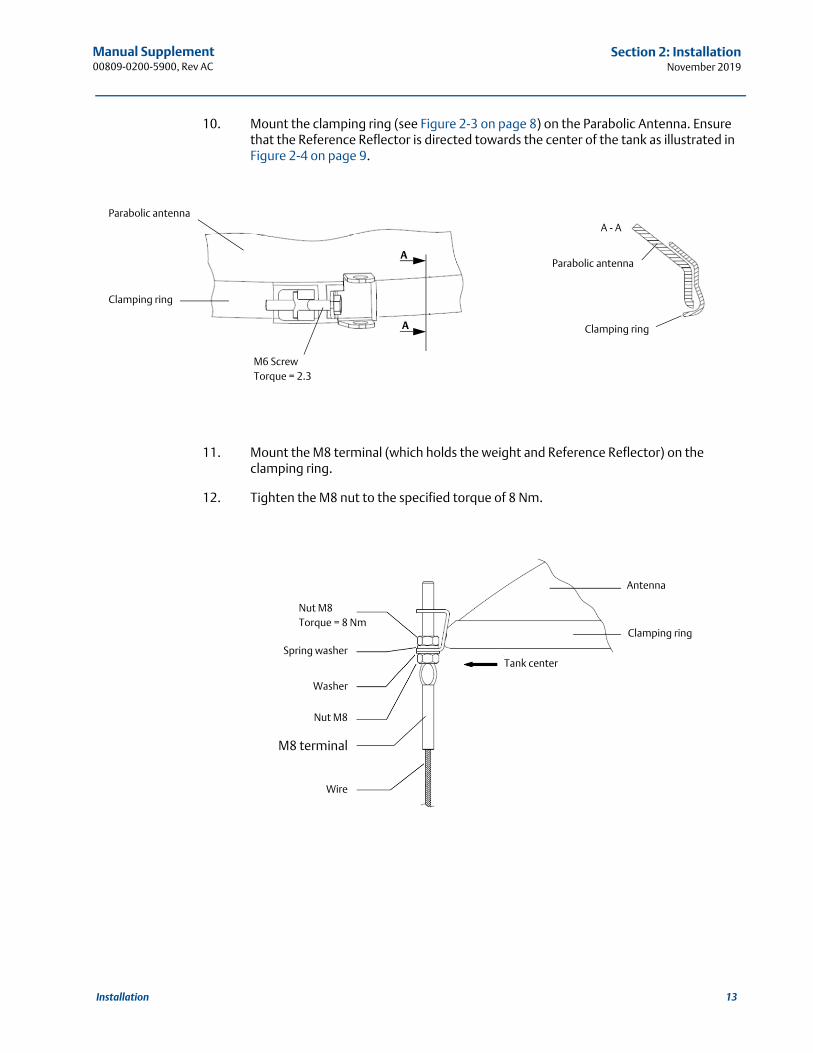
10. Mount the clamping ring (see Figure 2-3 on page 8) on the Parabolic Antenna. Ensure that the Reference Reflector is directed towards the center of the tank as illustrated in Figure 2-4 on page 9.
11. Mount the M8 terminal (which holds the weight and Reference Reflector) on the clamping ring.
12. Tighten the M8 nut to the specified torque of 8 Nm.
Parabolic antennaA - A
M6 ScrewTorque = 2.3
Clamping ring
A
A Clamping ring
Parabolic antenna
Nut M8Torque = 8 Nm
Tank center
Nut M8
Spring washer
Washer
Wire
M8 terminal
Clamping ring
Antenna
13Installation
Manual Supplement00809-0200-5900, Rev AC
Section 2: InstallationNovember 2019
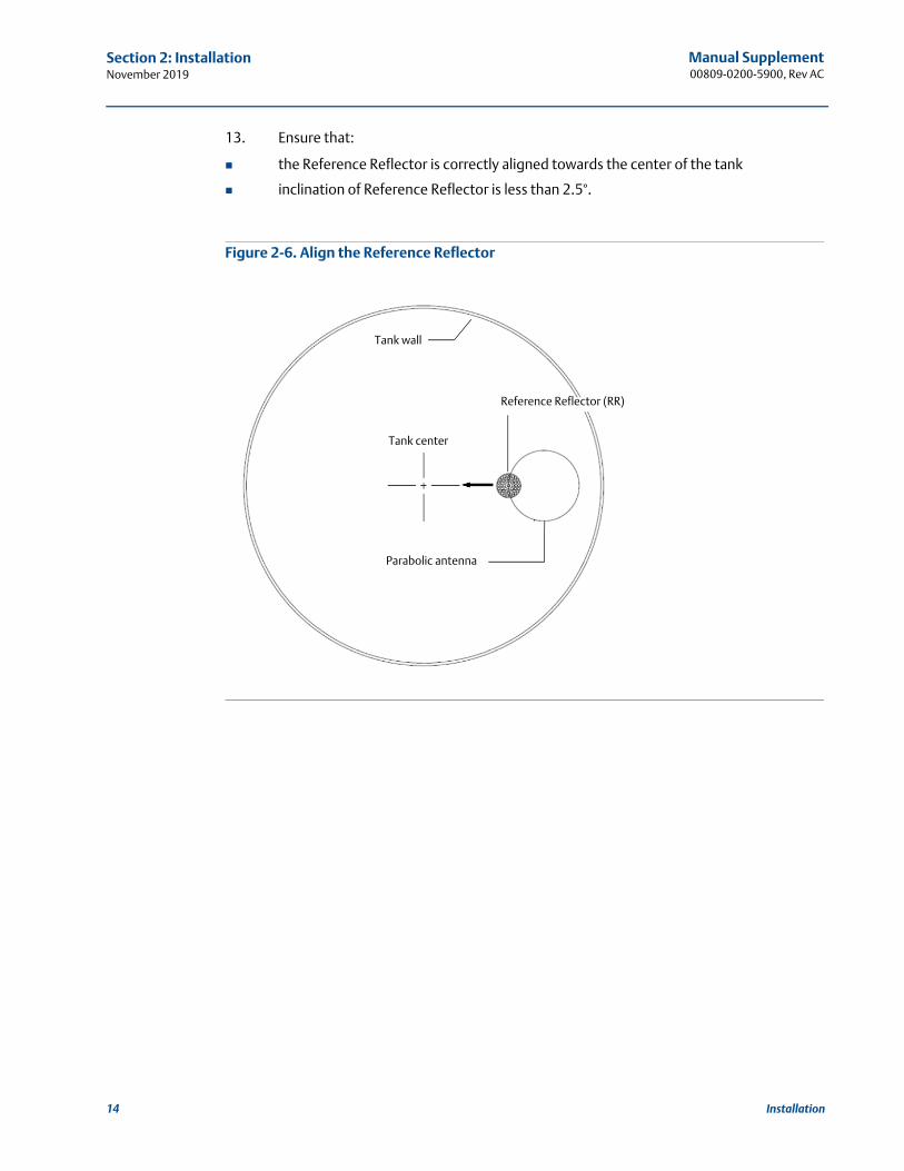
13. Ensure that:
the Reference Reflector is correctly aligned towards the center of the tank
inclination of Reference Reflector is less than 2.5°.
Figure 2-6. Align the Reference Reflector
Reference Reflector (RR)
Tank center
Parabolic antenna
Tank wall
14 Installation
Manual Supplement00809-0200-5900, Rev AC
Section 2: InstallationNovember 2019
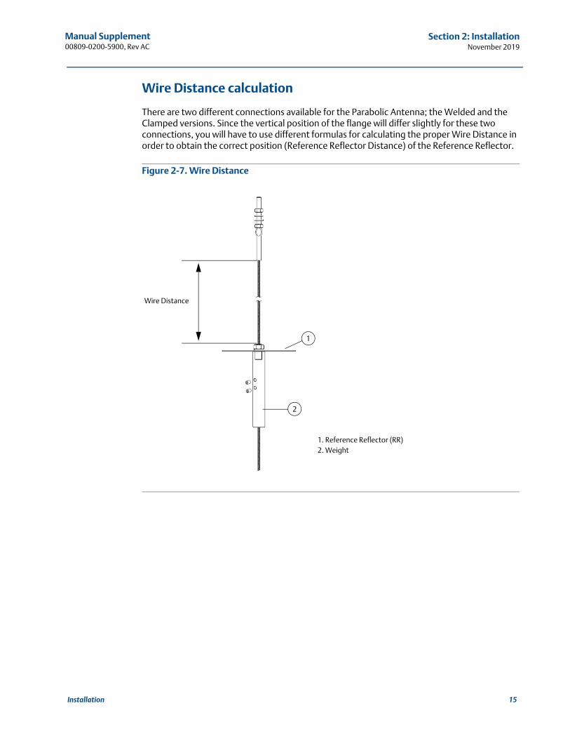
Wire Distance calculation
There are two different connections available for the Parabolic Antenna; the Welded and the Clamped versions. Since the vertical position of the flange will differ slightly for these two connections, you will have to use different formulas for calculating the proper Wire Distance in order to obtain the correct position (Reference Reflector Distance) of the Reference Reflector.
Figure 2-7. Wire Distance
1
2
Wire Distance
1. Reference Reflector (RR)2. Weight
15Installation
Manual Supplement00809-0200-5900, Rev AC
Section 2: InstallationNovember 2019
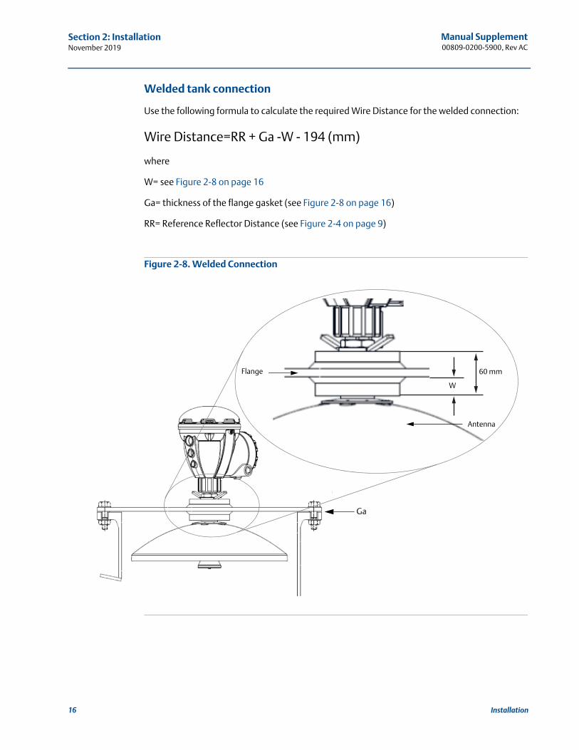
Welded tank connection
Use the following formula to calculate the required Wire Distance for the welded connection:
Wire Distance=RR + Ga -W - 194 (mm)
where
W= see Figure 2-8 on page 16
Ga= thickness of the flange gasket (see Figure 2-8 on page 16)
RR= Reference Reflector Distance (see Figure 2-4 on page 9)
Figure 2-8. Welded Connection
60 mmFlange
Antenna
W
Ga
16 Installation
Manual Supplement00809-0200-5900, Rev AC
Section 2: InstallationNovember 2019
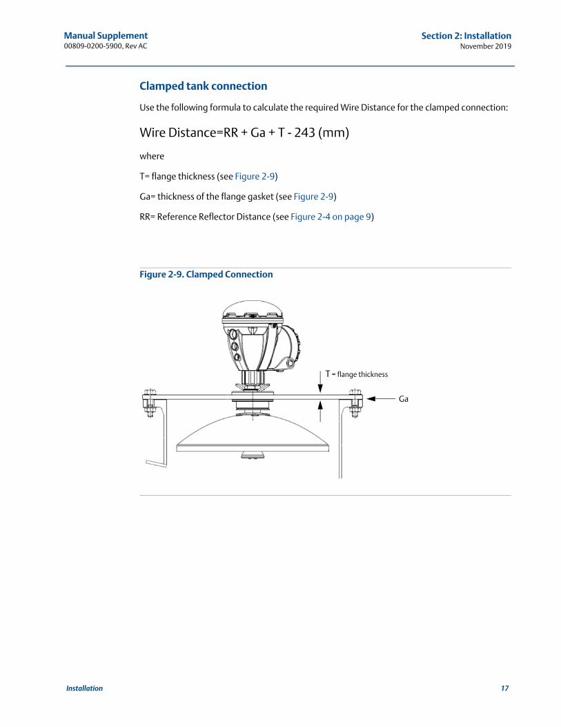
Clamped tank connection
Use the following formula to calculate the required Wire Distance for the clamped connection:
Wire Distance=RR + Ga + T - 243 (mm)
where
T= flange thickness (see Figure 2-9)
Ga= thickness of the flange gasket (see Figure 2-9)
RR= Reference Reflector Distance (see Figure 2-4 on page 9)
Figure 2-9. Clamped Connection
T = flange thickness
Ga
17Installation
Manual Supplement00809-0200-5900, Rev AC
Section 2: InstallationNovember 2019
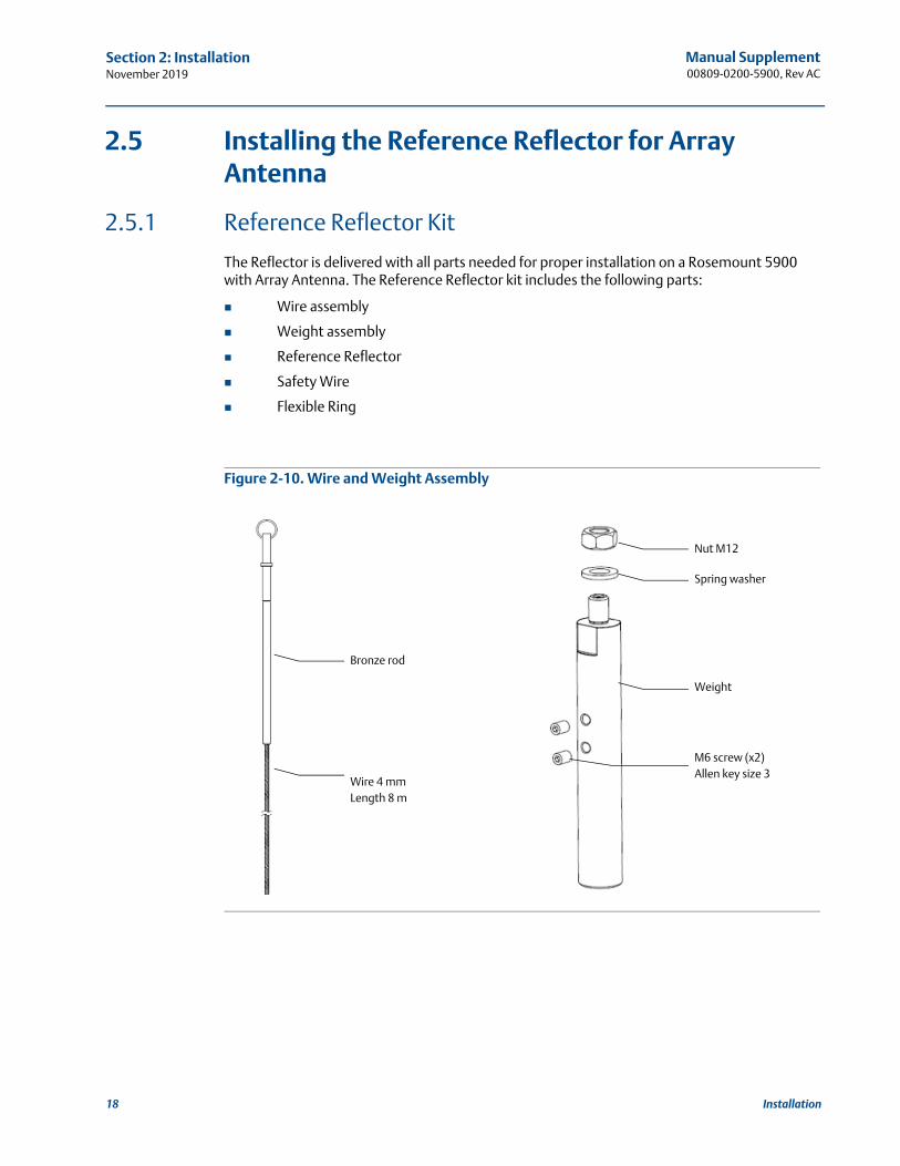
2.5 Installing the Reference Reflector for Array Antenna
2.5.1 Reference Reflector Kit
The Reflector is delivered with all parts needed for proper installation on a Rosemount 5900 with Array Antenna. The Reference Reflector kit includes the following parts:
Wire assembly
Weight assembly
Reference Reflector
Safety Wire
Flexible Ring
Figure 2-10. Wire and Weight Assembly
Nut M12
Spring washer
Weight
M6 screw (x2)Allen key size 3
Bronze rod
Wire 4 mmLength 8 m
18 Installation
Manual Supplement00809-0200-5900, Rev AC
Section 2: InstallationNovember 2019
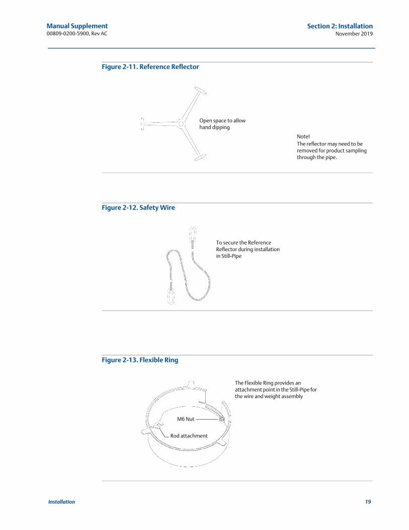
Figure 2-11. Reference Reflector
Figure 2-12. Safety Wire
Figure 2-13. Flexible Ring
Open space to allow hand dipping
Note! The reflector may need to be removed for product sampling through the pipe.
To secure the Reference Reflector during installation in Still-Pipe
M6 Nut
Rod attachment
The Flexible Ring provides an attachment point in the Still-Pipe for the wire and weight assembly
19Installation
Manual Supplement00809-0200-5900, Rev AC
Section 2: InstallationNovember 2019
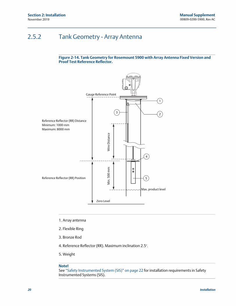
2.5.2 Tank Geometry - Array Antenna
Figure 2-14. Tank Geometry for Rosemount 5900 with Array Antenna Fixed Version and Proof Test Reference Reflector.
1. Array antenna
2. Flexible Ring
3. Bronze Rod
4. Reference Reflector (RR). Maximum inclination 2.5°.
5. Weight
Note!See “Safety Instrumented System (SIS)” on page 22 for installation requirements in Safety Instrumented Systems (SIS).
Wire
Dis
tanc
e
Reference Reflector (RR) DistanceMinimum: 1000 mmMaximum: 8000 mm
Reference Reflector (RR) Position
Min
. 500
mm
4
5
Zero Level
Max. product level
Gauge Reference Point
1
3 2
20 Installation
Manual Supplement00809-0200-5900, Rev AC
Section 2: InstallationNovember 2019
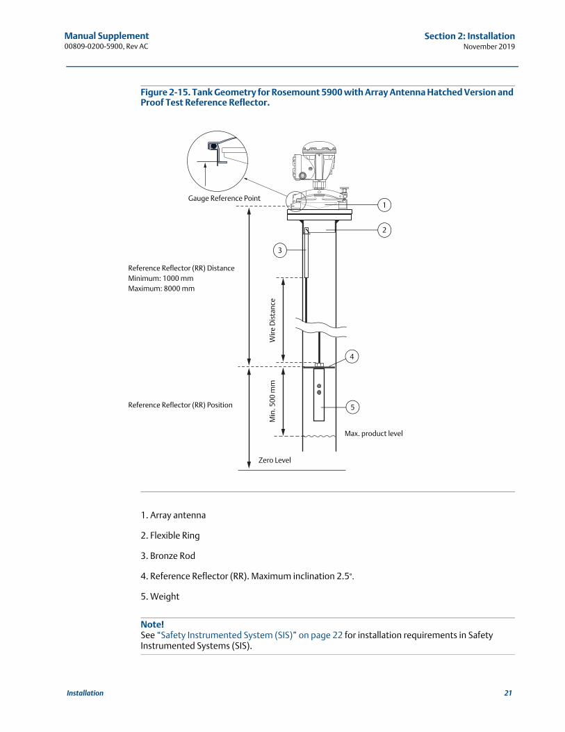
Figure 2-15. Tank Geometry for Rosemount 5900 with Array Antenna Hatched Version and Proof Test Reference Reflector.
1. Array antenna
2. Flexible Ring
3. Bronze Rod
4. Reference Reflector (RR). Maximum inclination 2.5°.
5. Weight
Note!See “Safety Instrumented System (SIS)” on page 22 for installation requirements in Safety Instrumented Systems (SIS).
Wire
Dis
tanc
eReference Reflector (RR) DistanceMinimum: 1000 mmMaximum: 8000 mm
Reference Reflector (RR) Position
Min
. 500
mm
4
5
Zero Level
Max. product level
Gauge Reference Point1
2
3
21Installation
Manual Supplement00809-0200-5900, Rev AC
Section 2: InstallationNovember 2019
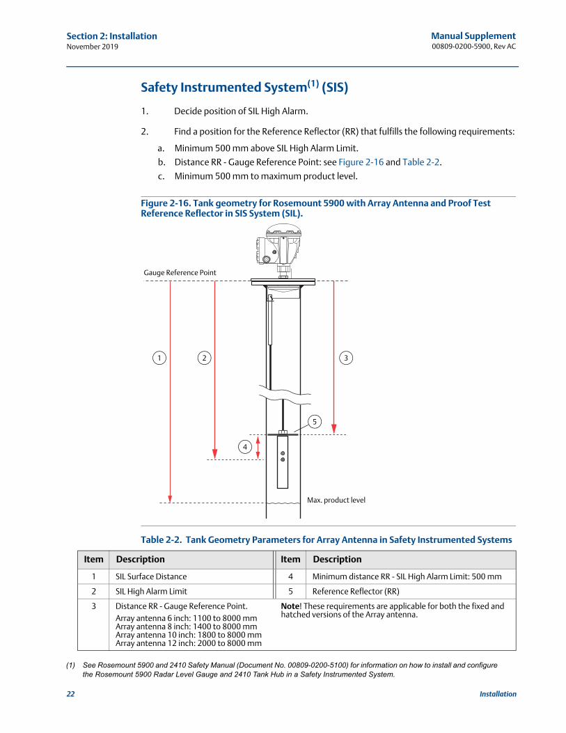
Safety Instrumented System(1) (SIS)
1. Decide position of SIL High Alarm.
2. Find a position for the Reference Reflector (RR) that fulfills the following requirements:
a. Minimum 500 mm above SIL High Alarm Limit.
b. Distance RR - Gauge Reference Point: see Figure 2-16 and Table 2-2.
c. Minimum 500 mm to maximum product level.
Figure 2-16. Tank geometry for Rosemount 5900 with Array Antenna and Proof Test Reference Reflector in SIS System (SIL).
Table 2-2. Tank Geometry Parameters for Array Antenna in Safety Instrumented Systems
(1) See Rosemount 5900 and 2410 Safety Manual (Document No. 00809-0200-5100) for information on how to install and configure the Rosemount 5900 Radar Level Gauge and 2410 Tank Hub in a Safety Instrumented System.
Item Description Item Description
1 SIL Surface Distance 4 Minimum distance RR - SIL High Alarm Limit: 500 mm
2 SIL High Alarm Limit 5 Reference Reflector (RR)
3 Distance RR - Gauge Reference Point. Array antenna 6 inch: 1100 to 8000 mmArray antenna 8 inch: 1400 to 8000 mmArray antenna 10 inch: 1800 to 8000 mmArray antenna 12 inch: 2000 to 8000 mm
Note! These requirements are applicable for both the fixed and hatched versions of the Array antenna.
4
21
Max. product level
Gauge Reference Point
5
3
22 Installation
Manual Supplement00809-0200-5900, Rev AC
Section 2: InstallationNovember 2019
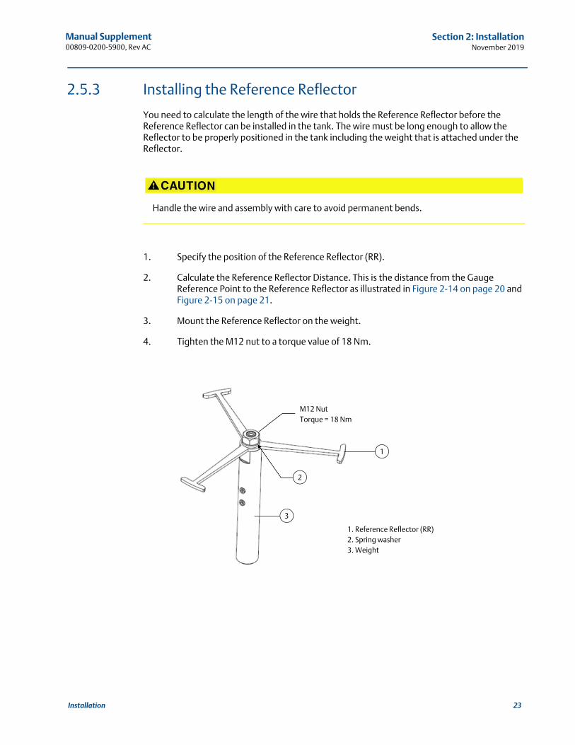
2.5.3 Installing the Reference Reflector
You need to calculate the length of the wire that holds the Reference Reflector before the Reference Reflector can be installed in the tank. The wire must be long enough to allow the Reflector to be properly positioned in the tank including the weight that is attached under the Reflector.
1. Specify the position of the Reference Reflector (RR).
2. Calculate the Reference Reflector Distance. This is the distance from the Gauge Reference Point to the Reference Reflector as illustrated in Figure 2-14 on page 20 and Figure 2-15 on page 21.
3. Mount the Reference Reflector on the weight.
4. Tighten the M12 nut to a torque value of 18 Nm.
Handle the wire and assembly with care to avoid permanent bends.
1
3
1. Reference Reflector (RR)2. Spring washer3. Weight
M12 NutTorque = 18 Nm
2
23Installation
Manual Supplement00809-0200-5900, Rev AC
Section 2: InstallationNovember 2019
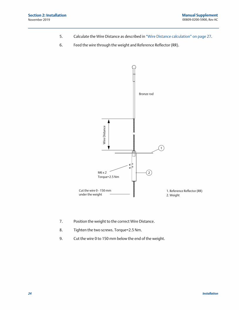
5. Calculate the Wire Distance as described in “Wire Distance calculation” on page 27.
6. Feed the wire through the weight and Reference Reflector (RR).
7. Position the weight to the correct Wire Distance.
8. Tighten the two screws. Torque=2.5 Nm.
9. Cut the wire 0 to 150 mm below the end of the weight.
1
2
Wire
Dis
tanc
e
1. Reference Reflector (RR)2. Weight
M6 x 2Torque=2.5 Nm
Cut the wire 0 - 150 mm under the weight
Bronze rod
24 Installation
Manual Supplement00809-0200-5900, Rev AC
Section 2: InstallationNovember 2019
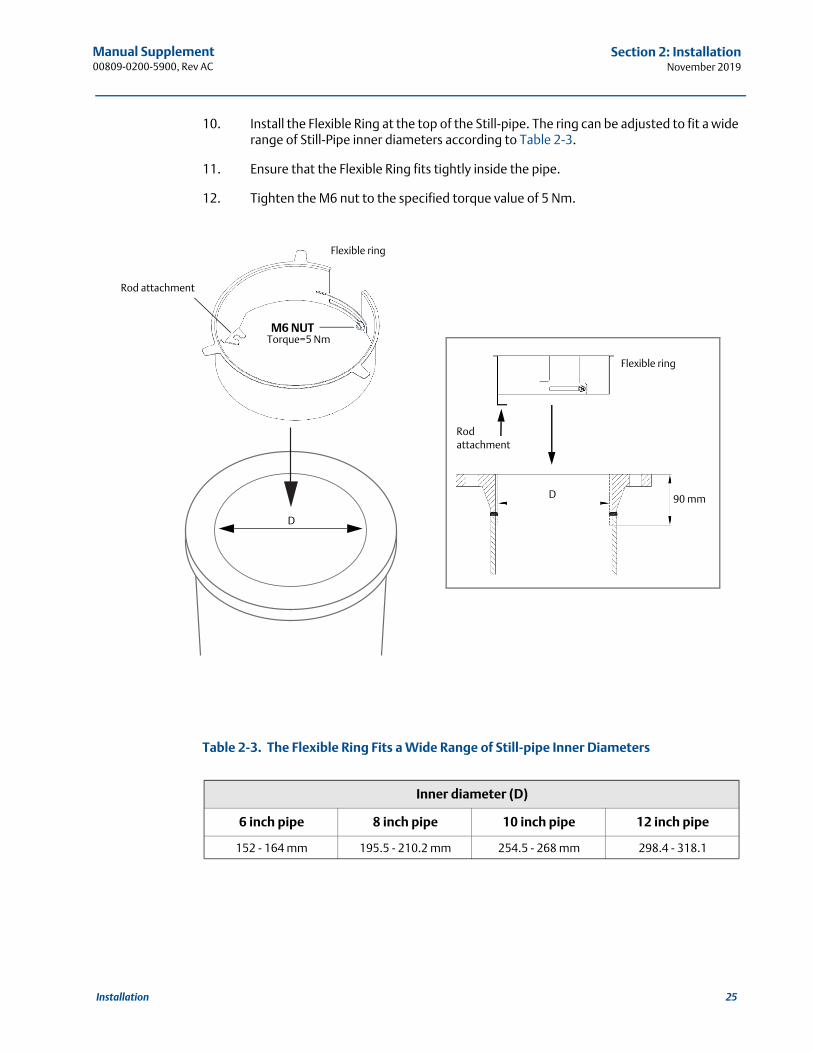
10. Install the Flexible Ring at the top of the Still-pipe. The ring can be adjusted to fit a wide range of Still-Pipe inner diameters according to Table 2-3.
11. Ensure that the Flexible Ring fits tightly inside the pipe.
12. Tighten the M6 nut to the specified torque value of 5 Nm.
Table 2-3. The Flexible Ring Fits a Wide Range of Still-pipe Inner Diameters
Inner diameter (D)
6 inch pipe 8 inch pipe 10 inch pipe 12 inch pipe
152 - 164 mm 195.5 - 210.2 mm 254.5 - 268 mm 298.4 - 318.1
D 90 mm
M6 NUTTorque=5 Nm
D
Flexible ring
Flexible ring
Rod attachment
Rod attachment
25Installation
Manual Supplement00809-0200-5900, Rev AC
Section 2: InstallationNovember 2019
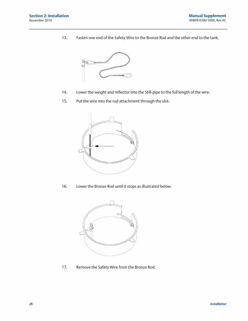
13. Fasten one end of the Safety Wire to the Bronze Rod and the other end to the tank.
14. Lower the weight and reflector into the Still-pipe to the full length of the wire.
15. Put the wire into the rod attachment through the slot.
16. Lower the Bronze Rod until it stops as illustrated below.
17. Remove the Safety Wire from the Bronze Rod.
26 Installation
Manual Supplement00809-0200-5900, Rev AC
Section 2: InstallationNovember 2019
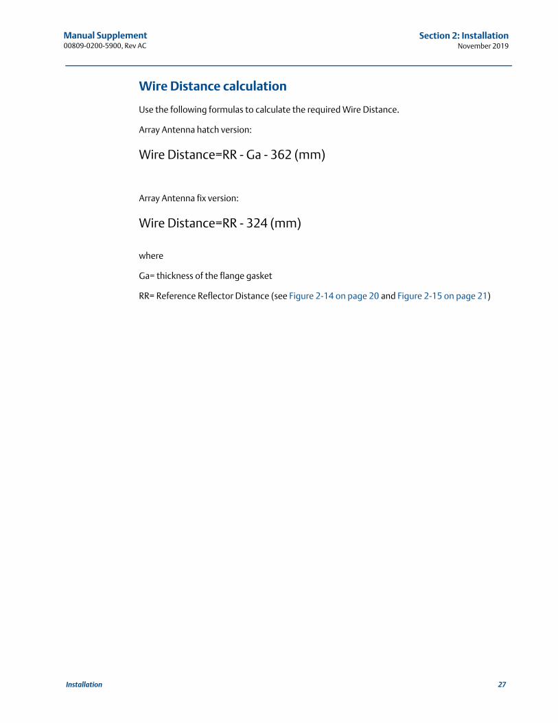
Wire Distance calculation
Use the following formulas to calculate the required Wire Distance.
Array Antenna hatch version:
Wire Distance=RR - Ga - 362 (mm)
Array Antenna fix version:
Wire Distance=RR - 324 (mm)
where
Ga= thickness of the flange gasket
RR= Reference Reflector Distance (see Figure 2-14 on page 20 and Figure 2-15 on page 21)
27Installation

Manual Supplement00809-0200-5900, Rev AC
Section 2: InstallationNovember 2019
28 Installation
Manual Supplement00809-0200-5900, Rev AC
Section 3: Configuration of Reference ReflectorNovember 2019
Section 3 Configuration of Reference Reflector
Overview . . . . . . . . . . . . . . . . . . . . . . . . . . . . . . . . . . . . . . . . . . . . . . . . . . . . . . . . . . . . . . . . . . page 29Safety messages . . . . . . . . . . . . . . . . . . . . . . . . . . . . . . . . . . . . . . . . . . . . . . . . . . . . . . . . . . . . page 29Configuration using TankMaster WinSetup . . . . . . . . . . . . . . . . . . . . . . . . . . . . . . . . . . . . . page 30
3.1 Overview
The information in this section covers configuration and calibration of the Reference Reflector for proof testing the Rosemount™ 5900 Radar Level Gauge.
3.2 Safety messages
Procedures and instructions in this section may require special precautions to ensure the safety of the personnel performing the operations. Information that raises potential safety issues is
indicated by a warning symbol ( ). Refer to the following safety messages before performing an operation preceded by this symbol.
Failure to follow safe installation and servicing guidelines could result in death or serious injury:
Make sure only qualified personnel perform the installation.
Use the equipment only as specified in this manual. Failure to do so may impair the protection provided by the equipment.
Do not perform any service other than those contained in this manual unless you are qualified.
Physical access
Unauthorized personnel may potentially cause significant damage to and/or misconfiguration of end user’s equipment. This could be intentional or unintentional and needs to be protected against.
Physical security is an important part of any security program and fundamental to protecting your system. Restrict physical access by unauthorized personnel to protect end user’s assets. This is true for all systems used within the facility.
29Configuration of Reference Reflector
Manual Supplement00809-0200-5900, Rev AC
Section 3: Configuration of Reference ReflectorNovember 2019
3.3 Configuration using TankMaster WinSetup
3.3.1 Introduction
The Rosemount 5900 is configured by using the TankMaster Winsetup configuration program. WinSetup supports standard configuration of the Rosemount 5900 Radar Level Gauge as well as configuration of the Reference Reflector for Proof Test applications.
See the Tank Gauging System Configuration Manual for more information on using the TankMaster WinSetup software to configure a Rosemount Tank Gauging system.
NoteThe Proof Test function requires gauge firmware version 1.B9 or higher and Rosemount TankMaster 6.E1 or higher .
Proof test features
The Rosemount 5900 Proof Test function in TankMaster Winsetup includes the following functions:
Configure proof test
Perform proof test
View proof test history
Schedule proof tests
3.3.2 Considerations
The following requirements and recommendations must be considered when using the Rosemount 5900 Proof Test function:
Do not perform calibration of Proof Test function during activities in the tank, for example when it is filled or emptied.
Do not perform calibration of Proof Test function during extreme environmental conditions.
Proof Test calibration must be repeated whenever configuration of tank geometry parameters has been changed. This may for example include parameters such as Calibration Distance or Pipe Diameter.
For Still-Pipes the slots must not be wider than one inch (1”)
30 Configuration of Reference Reflector
Manual Supplement00809-0200-5900, Rev AC
Section 3: Configuration of Reference ReflectorNovember 2019
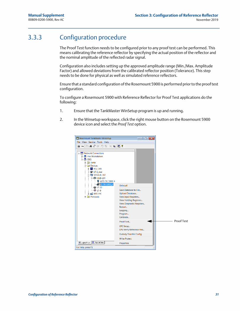
3.3.3 Configuration procedure
The Proof Test function needs to be configured prior to any proof test can be performed. This means calibrating the reference reflector by specifying the actual position of the reflector and the nominal amplitude of the reflected radar signal.
Configuration also includes setting up the approved amplitude range (Min./Max. Amplitude Factor) and allowed deviations from the calibrated reflector position (Tolerance). This step needs to be done for physical as well as simulated reference reflectors.
Ensure that a standard configuration of the Rosemount 5900 is performed prior to the proof test configuration.
To configure a Rosemount 5900 with Reference Reflector for Proof Test applications do the following:
1. Ensure that the TankMaster WinSetup program is up and running.
2. In the Winsetup workspace, click the right mouse button on the Rosemount 5900 device icon and select the Proof Test option.
Proof Test
31Configuration of Reference Reflector
Manual Supplement00809-0200-5900, Rev AC
Section 3: Configuration of Reference ReflectorNovember 2019
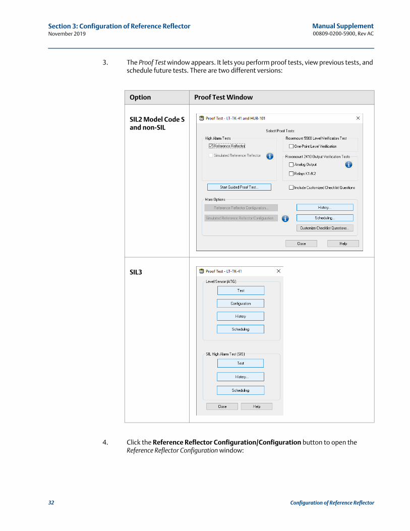
3. The Proof Test window appears. It lets you perform proof tests, view previous tests, and schedule future tests. There are two different versions:
4. Click the Reference Reflector Configuration/Configuration button to open the Reference Reflector Configuration window:
Option Proof Test Window
SIL2 Model Code S and non-SIL
SIL3
32 Configuration of Reference Reflector
Manual Supplement00809-0200-5900, Rev AC
Section 3: Configuration of Reference ReflectorNovember 2019
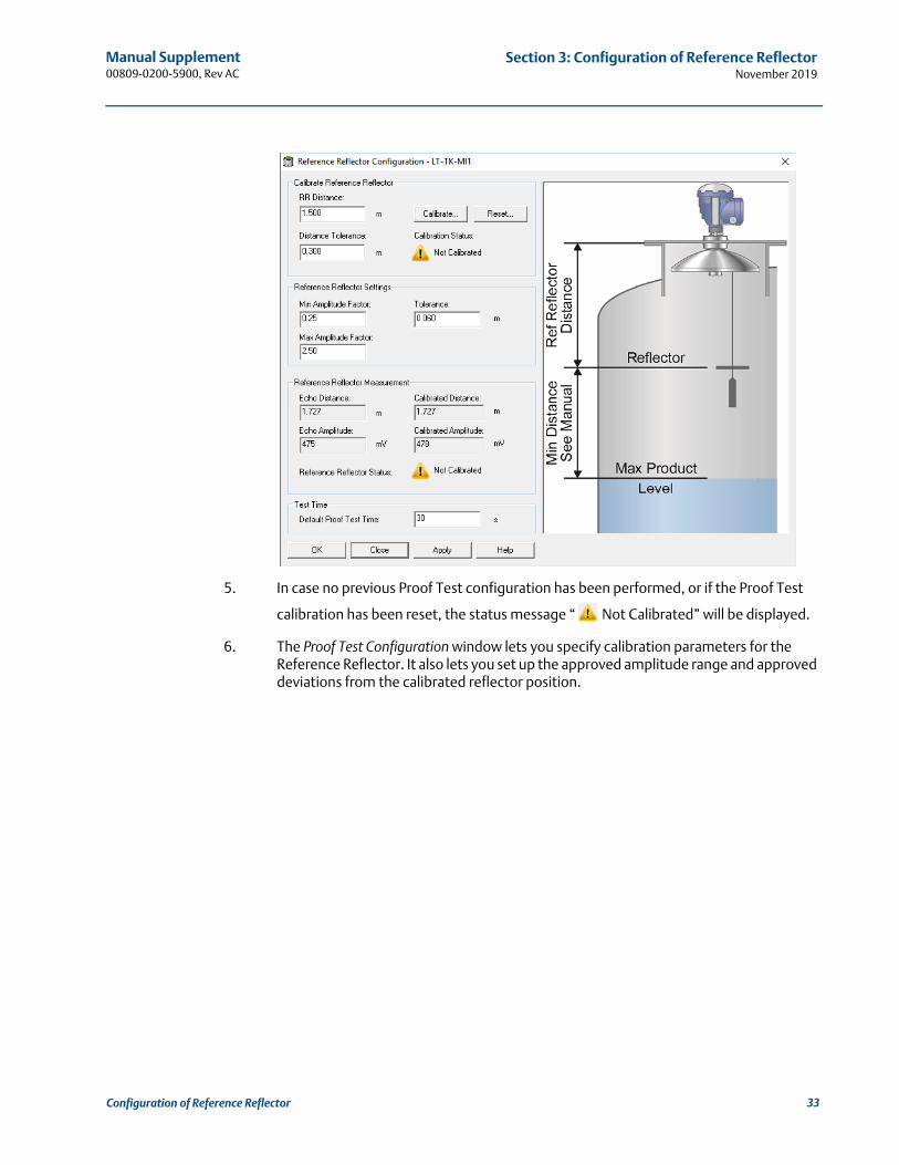
5. In case no previous Proof Test configuration has been performed, or if the Proof Test
calibration has been reset, the status message “ Not Calibrated” will be displayed.
6. The Proof Test Configuration window lets you specify calibration parameters for the Reference Reflector. It also lets you set up the approved amplitude range and approved deviations from the calibrated reflector position.
33Configuration of Reference Reflector
Manual Supplement00809-0200-5900, Rev AC
Section 3: Configuration of Reference ReflectorNovember 2019
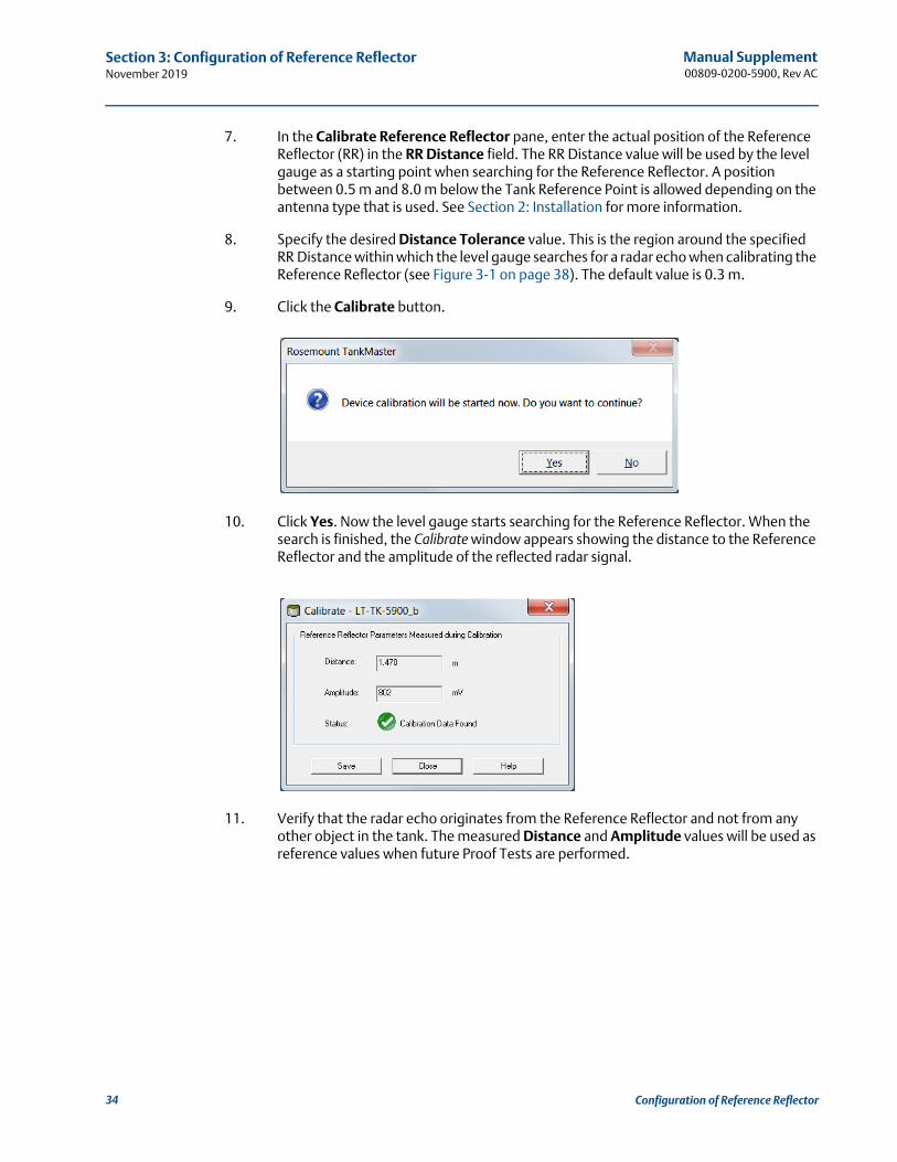
7. In the Calibrate Reference Reflector pane, enter the actual position of the Reference Reflector (RR) in the RR Distance field. The RR Distance value will be used by the level gauge as a starting point when searching for the Reference Reflector. A position between 0.5 m and 8.0 m below the Tank Reference Point is allowed depending on the antenna type that is used. See Section 2: Installation for more information.
8. Specify the desired Distance Tolerance value. This is the region around the specified RR Distance within which the level gauge searches for a radar echo when calibrating the Reference Reflector (see Figure 3-1 on page 38). The default value is 0.3 m.
9. Click the Calibrate button.
10. Click Yes. Now the level gauge starts searching for the Reference Reflector. When the search is finished, the Calibrate window appears showing the distance to the Reference Reflector and the amplitude of the reflected radar signal.
11. Verify that the radar echo originates from the Reference Reflector and not from any other object in the tank. The measured Distance and Amplitude values will be used as reference values when future Proof Tests are performed.
34 Configuration of Reference Reflector
Manual Supplement00809-0200-5900, Rev AC
Section 3: Configuration of Reference ReflectorNovember 2019
12. For Safety Instrumented Systems (SIL) verify that the amplitude is within the following recommended range:
Rosemount 5900 with Parabolic antenna: 600 to 1200 mV
Rosemount 5900 with Array antenna (Still-Pipe): 1000 to 3500 mV
Rosemount 5900 with simulated antenna: approximately 600 mV
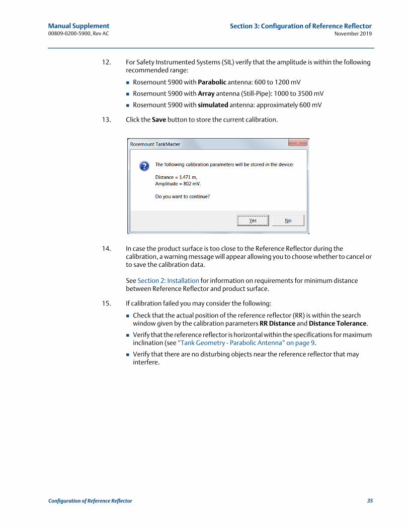
13. Click the Save button to store the current calibration.
14. In case the product surface is too close to the Reference Reflector during the calibration, a warning message will appear allowing you to choose whether to cancel or to save the calibration data.
See Section 2: Installation for information on requirements for minimum distance between Reference Reflector and product surface.
15. If calibration failed you may consider the following:
Check that the actual position of the reference reflector (RR) is within the search window given by the calibration parameters RR Distance and Distance Tolerance.
Verify that the reference reflector is horizontal within the specifications for maximum inclination (see “Tank Geometry - Parabolic Antenna” on page 9.
Verify that there are no disturbing objects near the reference reflector that may interfere.
35Configuration of Reference Reflector
Manual Supplement00809-0200-5900, Rev AC
Section 3: Configuration of Reference ReflectorNovember 2019
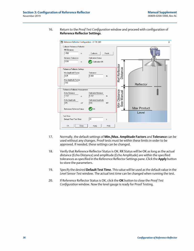
16. Return to the Proof Test Configuration window and proceed with configuration of Reference Reflector Settings.
17. Normally, the default settings of Min./Max. Amplitude Factors and Tolerance can be used without any changes. Proof tests must be within these limits in order to be approved. If needed, these settings can be changed.
18. Verify that Reference Reflector Status is OK. RR Status will be OK as long as the actual distance (Echo Distance) and amplitude (Echo Amplitude) are within the specified tolerances as specified in the Reference Reflector Settings pane. Click the Apply button to store the parameters.
19. Specify the desired Default Test Time. This value will be used as the default value in the Level Sensor Test window. The actual test time can be changed when running the test.
20. If Reference Reflector Status is OK, click the OK button to close the Proof Test Configuration window. Now the level gauge is ready for Proof Testing.
36 Configuration of Reference Reflector
Manual Supplement00809-0200-5900, Rev AC
Section 3: Configuration of Reference ReflectorNovember 2019
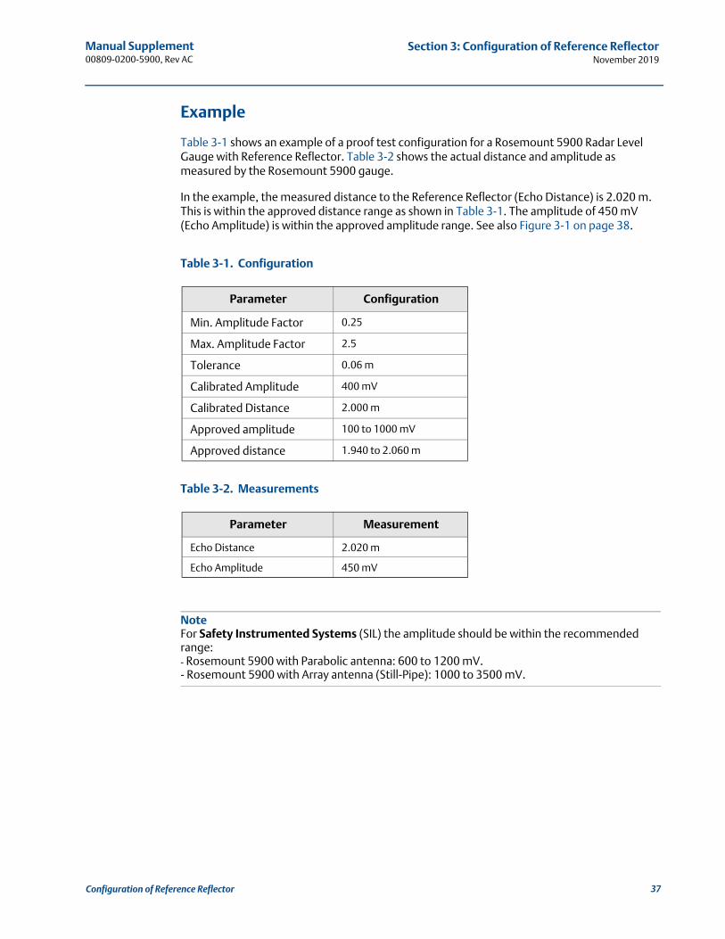
Example
Table 3-1 shows an example of a proof test configuration for a Rosemount 5900 Radar Level Gauge with Reference Reflector. Table 3-2 shows the actual distance and amplitude as measured by the Rosemount 5900 gauge.
In the example, the measured distance to the Reference Reflector (Echo Distance) is 2.020 m. This is within the approved distance range as shown in Table 3-1. The amplitude of 450 mV (Echo Amplitude) is within the approved amplitude range. See also Figure 3-1 on page 38.
Table 3-1. Configuration
Table 3-2. Measurements
NoteFor Safety Instrumented Systems (SIL) the amplitude should be within the recommended range:- Rosemount 5900 with Parabolic antenna: 600 to 1200 mV. - Rosemount 5900 with Array antenna (Still-Pipe): 1000 to 3500 mV.
Parameter Configuration
Min. Amplitude Factor 0.25
Max. Amplitude Factor 2.5
Tolerance 0.06 m
Calibrated Amplitude 400 mV
Calibrated Distance 2.000 m
Approved amplitude 100 to 1000 mV
Approved distance 1.940 to 2.060 m
Parameter Measurement
Echo Distance 2.020 m
Echo Amplitude 450 mV
37Configuration of Reference Reflector
Manual Supplement00809-0200-5900, Rev AC
Section 3: Configuration of Reference ReflectorNovember 2019
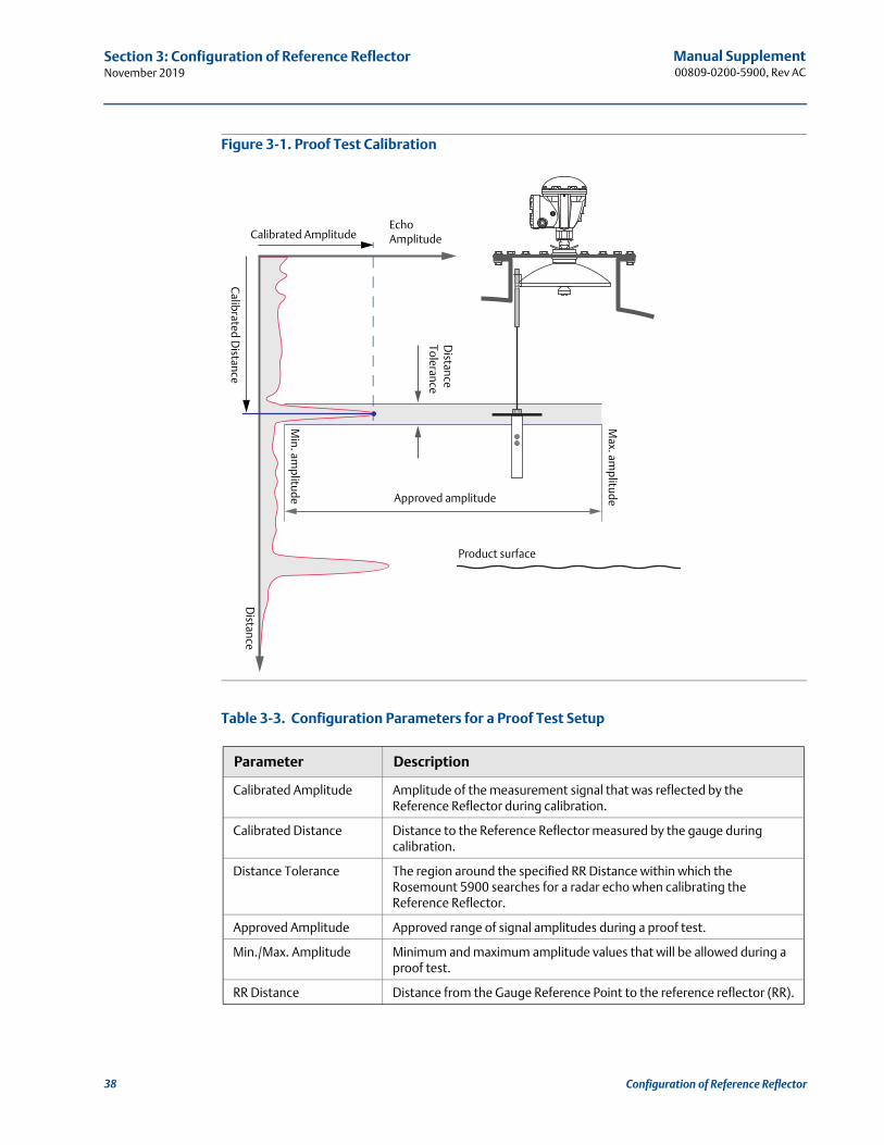
Figure 3-1. Proof Test Calibration
Table 3-3. Configuration Parameters for a Proof Test Setup
Parameter Description
Calibrated Amplitude Amplitude of the measurement signal that was reflected by the Reference Reflector during calibration.
Calibrated Distance Distance to the Reference Reflector measured by the gauge during calibration.
Distance Tolerance The region around the specified RR Distance within which the Rosemount 5900 searches for a radar echo when calibrating the Reference Reflector.
Approved Amplitude Approved range of signal amplitudes during a proof test.
Min./Max. Amplitude Minimum and maximum amplitude values that will be allowed during a proof test.
RR Distance Distance from the Gauge Reference Point to the reference reflector (RR).
Approved amplitude
Distance
Tolerance
Calibrated D
istanceD
istance
Echo AmplitudeCalibrated Amplitude
Max. am
plitude
Min. am
plitude
Product surface
38 Configuration of Reference Reflector
Manual Supplement 00809-0200-5900, Rev AC
Section 4: OperationNovember 2019
Section 4 Operation
Overview . . . . . . . . . . . . . . . . . . . . . . . . . . . . . . . . . . . . . . . . . . . . . . . . . . . . . . . . . . . . . . . . . . page 39Safety messages . . . . . . . . . . . . . . . . . . . . . . . . . . . . . . . . . . . . . . . . . . . . . . . . . . . . . . . . . . . . page 39Proof Test operation . . . . . . . . . . . . . . . . . . . . . . . . . . . . . . . . . . . . . . . . . . . . . . . . . . . . . . . . page 40Scheduling . . . . . . . . . . . . . . . . . . . . . . . . . . . . . . . . . . . . . . . . . . . . . . . . . . . . . . . . . . . . . . . . . page 44History . . . . . . . . . . . . . . . . . . . . . . . . . . . . . . . . . . . . . . . . . . . . . . . . . . . . . . . . . . . . . . . . . . . . page 46Reports . . . . . . . . . . . . . . . . . . . . . . . . . . . . . . . . . . . . . . . . . . . . . . . . . . . . . . . . . . . . . . . . . . . . page 47Removing a Reference Reflector . . . . . . . . . . . . . . . . . . . . . . . . . . . . . . . . . . . . . . . . . . . . . . page 50
4.1 Overview
This section contains information on the Light Emitting Diodes (LED) on the front of the Rosemount 2460 System Hub.
4.2 Safety messages
Procedures and instructions in this section may require special precautions to ensure the safety of the personnel performing the operations. Information that raises potential safety issues is
indicated by a warning symbol ( ). Refer to the following safety messages before performing an operation preceded by this symbol.
Failure to follow safe installation and servicing guidelines could result in death or serious injury:
Make sure only qualified personnel perform the installation.
Use the equipment only as specified in this manual. Failure to do so may impair the protection provided by the equipment.
Do not perform any service other than those contained in this manual unless you are qualified.
39Operation
Manual Supplement00809-0200-5900, Rev AC
Section 4: OperationNovember 2019
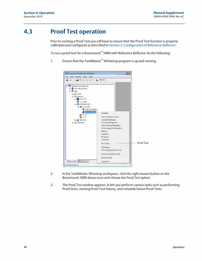
4.3 Proof Test operation
Prior to running a Proof Test you will have to ensure that the Proof Test function is properly calibrated and configured as described in Section 3: Configuration of Reference Reflector.
To run a proof test for a Rosemount™ 5900 with Reference Reflector do the following:
1. Ensure that the TankMaster™ WinSetup program is up and running.
2. In the TankMaster Winsetup workspace, click the right mouse button on the Rosemount 5900 device icon and choose the Proof Test option.
3. The Proof Test window appears. It lets you perform various tasks such as performing Proof tests, viewing Proof Test history, and schedule future Proof Tests.
Proof Test
40 Operation
Manual Supplement 00809-0200-5900, Rev AC
Section 4: OperationNovember 2019
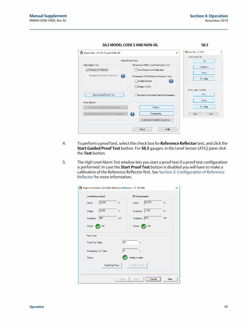
4. To perform a proof test, select the check box for Reference Reflector test, and click the Start Guided Proof Test button. For SIL3 gauges; in the Level Sensor (ATG) pane click the Test button.
5. The High Level Alarm Test window lets you start a proof test if a proof test configuration is performed. In case the Start Proof Test button is disabled you will have to make a calibration of the Reference Reflector first. See Section 3: Configuration of Reference Reflector for more information.
SIL2 MODEL CODE S AND NON-SIL SIL3
41Operation
Manual Supplement00809-0200-5900, Rev AC
Section 4: OperationNovember 2019
6. The following measurement data is presented:
7. Specify duration of the test in the Proof Test Time field. It can be set to any value between 30 seconds and 60 minutes. The default value is 120 seconds.
8. Ensure that device status is OK. See different status messages that may appear according to Table 4-1 on page 4-43.
9. Click the Start Proof Test button to perform the test for the specified Proof Test Time.
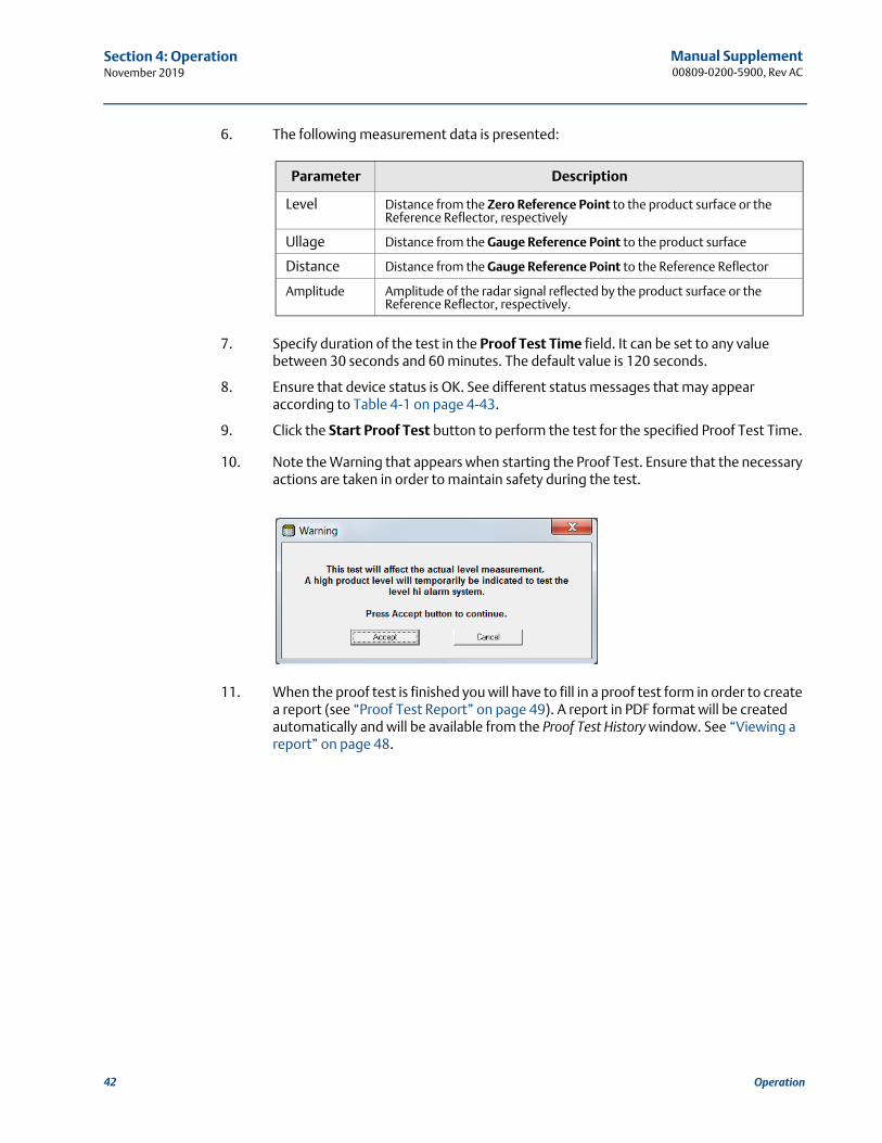
10. Note the Warning that appears when starting the Proof Test. Ensure that the necessary actions are taken in order to maintain safety during the test.
11. When the proof test is finished you will have to fill in a proof test form in order to create a report (see “Proof Test Report” on page 49). A report in PDF format will be created automatically and will be available from the Proof Test History window. See “Viewing a report” on page 48.
Parameter Description
Level Distance from the Zero Reference Point to the product surface or the Reference Reflector, respectively
Ullage Distance from the Gauge Reference Point to the product surface
Distance Distance from the Gauge Reference Point to the Reference Reflector
Amplitude Amplitude of the radar signal reflected by the product surface or the Reference Reflector, respectively.
42 Operation
Manual Supplement 00809-0200-5900, Rev AC
Section 4: OperationNovember 2019
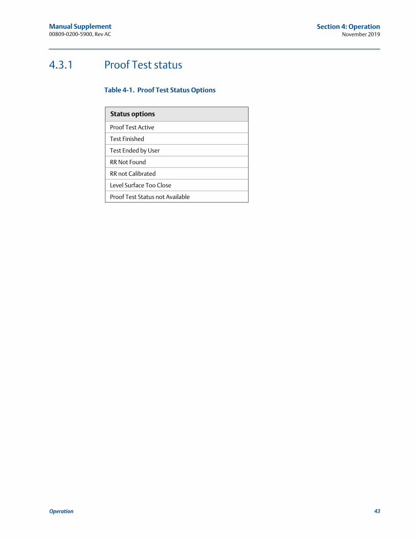
4.3.1 Proof Test status
Table 4-1. Proof Test Status Options
Status options
Proof Test Active
Test Finished
Test Ended by User
RR Not Found
RR not Calibrated
Level Surface Too Close
Proof Test Status not Available
43Operation
Manual Supplement00809-0200-5900, Rev AC
Section 4: OperationNovember 2019
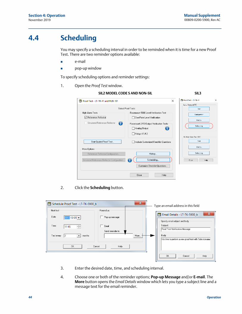
4.4 Scheduling
You may specify a scheduling interval in order to be reminded when it is time for a new Proof Test. There are two reminder options available:
pop-up window
To specify scheduling options and reminder settings:
1. Open the Proof Test window.
2. Click the Scheduling button.
3. Enter the desired date, time, and scheduling interval.
4. Choose one or both of the reminder options; Pop-up Message and/or E-mail. The More button opens the Email Details window which lets you type a subject line and a message text for the email reminder.
SIL2 MODEL CODE S AND NON-SIL SIL3
Type an email address in this field
44 Operation
Manual Supplement 00809-0200-5900, Rev AC
Section 4: OperationNovember 2019
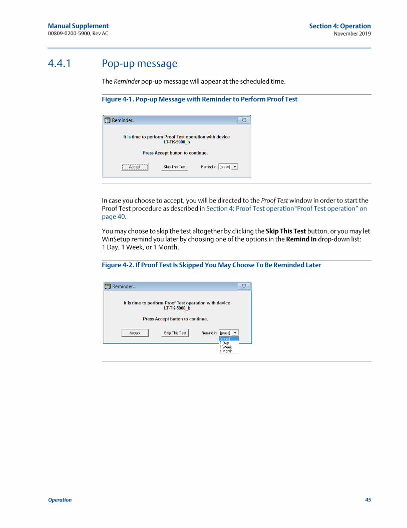
4.4.1 Pop-up message
The Reminder pop-up message will appear at the scheduled time.
Figure 4-1. Pop-up Message with Reminder to Perform Proof Test
In case you choose to accept, you will be directed to the Proof Test window in order to start the Proof Test procedure as described in Section 4: Proof Test operation“Proof Test operation” on page 40.
You may choose to skip the test altogether by clicking the Skip This Test button, or you may let WinSetup remind you later by choosing one of the options in the Remind In drop-down list:1 Day, 1 Week, or 1 Month.
Figure 4-2. If Proof Test Is Skipped You May Choose To Be Reminded Later
45Operation
Manual Supplement00809-0200-5900, Rev AC
Section 4: OperationNovember 2019
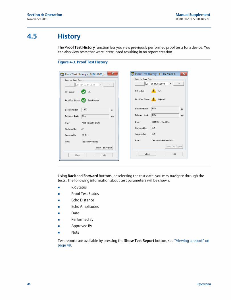
4.5 History
The Proof Test History function lets you view previously performed proof tests for a device. You can also view tests that were interrupted resulting in no report creation.
Figure 4-3. Proof Test History
Using Back and Forward buttons, or selecting the test date, you may navigate through the tests. The following information about test parameters will be shown:
RR Status
Proof Test Status
Echo Distance
Echo Amplitudes
Date
Performed By
Approved By
Note
Test reports are available by pressing the Show Test Report button, see “Viewing a report” on page 48.
46 Operation
Manual Supplement 00809-0200-5900, Rev AC
Section 4: OperationNovember 2019
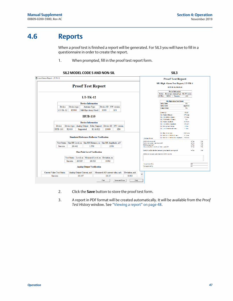
4.6 Reports
When a proof test is finished a report will be generated. For SIL3 you will have to fill in a questionnaire in order to create the report.
1. When prompted, fill in the proof test report form.
2. Click the Save button to store the proof test form.
3. A report in PDF format will be created automatically. It will be available from the Proof Test History window. See “Viewing a report” on page 48.
SIL2 MODEL CODE S AND NON-SIL SIL3
47Operation
Manual Supplement00809-0200-5900, Rev AC
Section 4: OperationNovember 2019
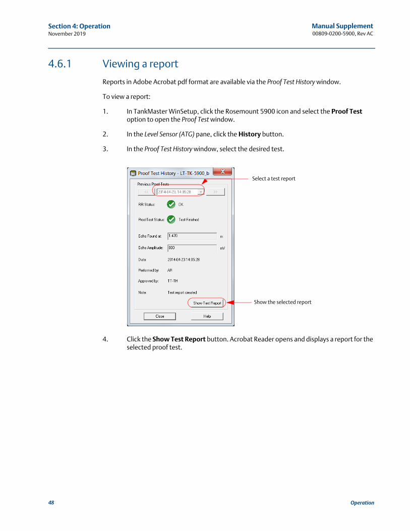
4.6.1 Viewing a report
Reports in Adobe Acrobat pdf format are available via the Proof Test History window.
To view a report:
1. In TankMaster WinSetup, click the Rosemount 5900 icon and select the Proof Test option to open the Proof Test window.
2. In the Level Sensor (ATG) pane, click the History button.
3. In the Proof Test History window, select the desired test.
4. Click the Show Test Report button. Acrobat Reader opens and displays a report for the selected proof test.
Show the selected report
Select a test report
48 Operation
Manual Supplement 00809-0200-5900, Rev AC
Section 4: OperationNovember 2019
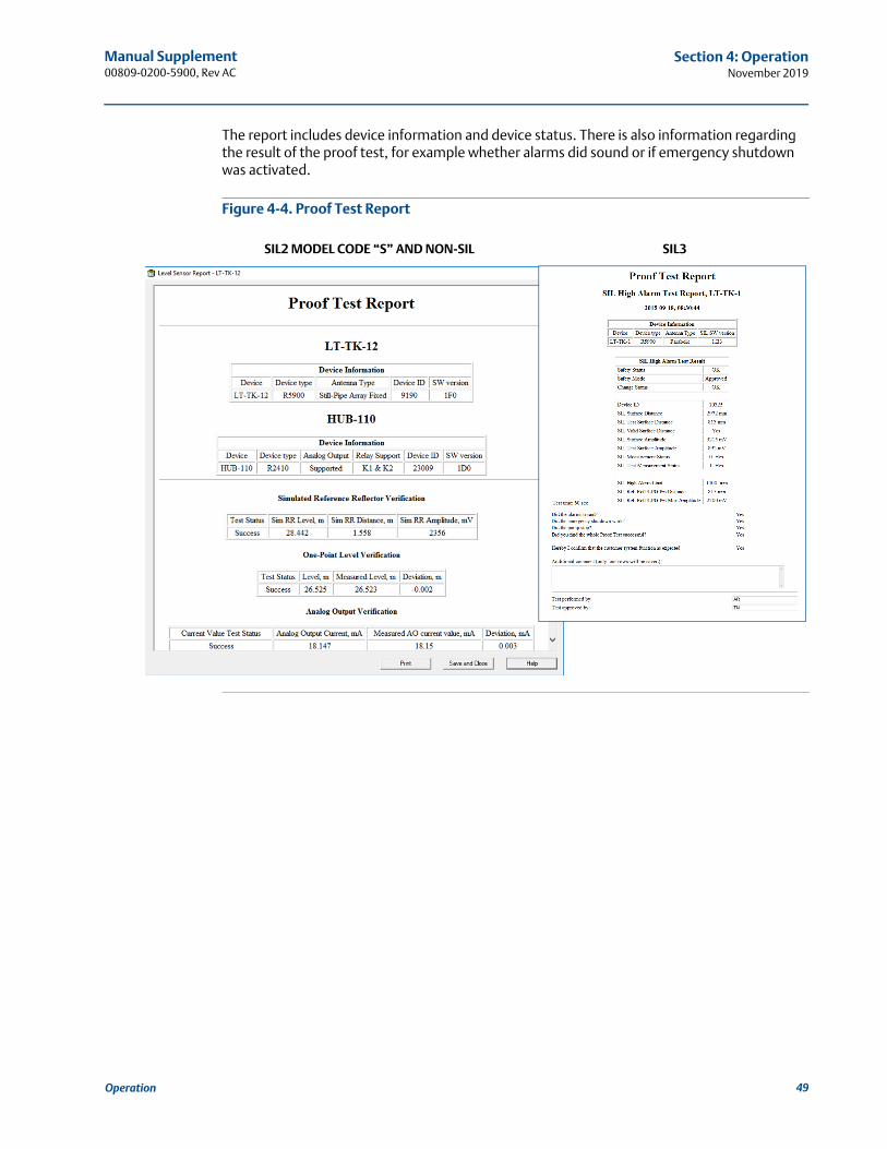
The report includes device information and device status. There is also information regarding the result of the proof test, for example whether alarms did sound or if emergency shutdown was activated.
Figure 4-4. Proof Test Report
SIL2 MODEL CODE “S” AND NON-SIL SIL3
49Operation
Manual Supplement00809-0200-5900, Rev AC
Section 4: OperationNovember 2019
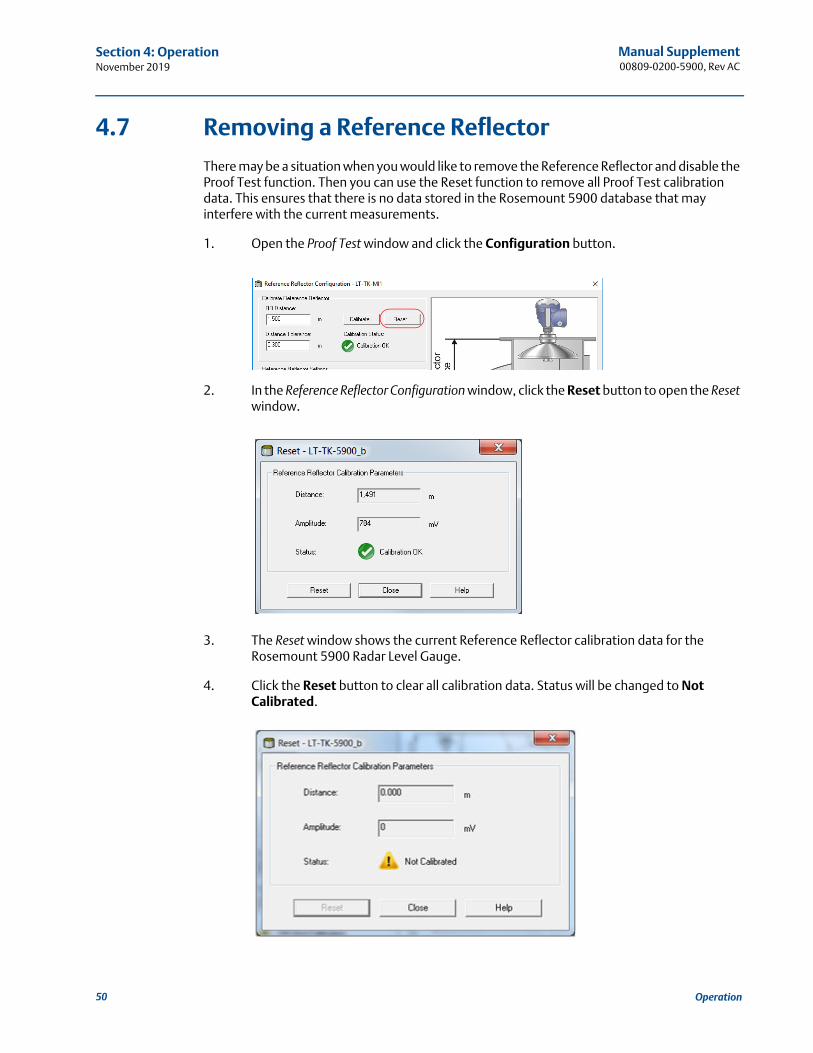
4.7 Removing a Reference Reflector
There may be a situation when you would like to remove the Reference Reflector and disable the Proof Test function. Then you can use the Reset function to remove all Proof Test calibration data. This ensures that there is no data stored in the Rosemount 5900 database that may interfere with the current measurements.
1. Open the Proof Test window and click the Configuration button.
2. In the Reference Reflector Configuration window, click the Reset button to open the Reset window.
3. The Reset window shows the current Reference Reflector calibration data for the Rosemount 5900 Radar Level Gauge.
4. Click the Reset button to clear all calibration data. Status will be changed to Not Calibrated.
50 Operation
Manual Supplement 00809-0200-5900, Rev AC
Section 5: Service and TroubleshootingNovember 2019
Section 5 Service and Troubleshooting
Safety messages . . . . . . . . . . . . . . . . . . . . . . . . . . . . . . . . . . . . . . . . . . . . . . . . . . . . . . . . . . . . page 51Troubleshooting . . . . . . . . . . . . . . . . . . . . . . . . . . . . . . . . . . . . . . . . . . . . . . . . . . . . . . . . . . . . page 52Tank spectrum . . . . . . . . . . . . . . . . . . . . . . . . . . . . . . . . . . . . . . . . . . . . . . . . . . . . . . . . . . . . . page 53
5.1 Safety messages
Procedures and instructions in this section may require special precautions to ensure the safety of the personnel performing the operations. Information that raises potential safety issues is indicated by a warning symbol ( ). Refer to the following safety messages before performing an operation preceded by this symbol.
Failure to follow safe installation and servicing guidelines could result in death or serious injury:
Make sure only qualified personnel perform the installation.
Use the equipment only as specified in this manual. Failure to do so may impair the protection provided by the equipment.
Do not perform any service other than those contained in this manual unless you are qualified.
High voltage that may be present on leads could cause electrical shock:
Avoid contact with leads and terminals.
Make sure the main power to the 2410 Tank Hub is off and the lines to any other external power source are disconnected or not powered while wiring the 2460.
51Service and Troubleshooting
Manual Supplement00809-0200-5900, Rev AC
Section 5: Service and TroubleshootingNovember 2019
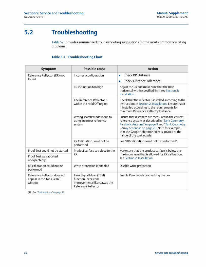
5.2 Troubleshooting
Table 5-1 provides summarized troubleshooting suggestions for the most common operating problems.
Table 5-1. Troubleshooting Chart
Symptom Possible cause Action
Reference Reflector (RR) not found
Incorrect configuration Check RR Distance
Check Distance Tolerance
RR inclination too high Adjust the RR and make sure that the RR is horizontal within specified limit see Section 2: Installation.
The Reference Reflector is within the Hold Off region
Check that the reflector is installed according to the instructions in Section 2: Installation. Ensure that it is installed according to the requirements for minimum Reference Reflector Distance.
Wrong search window due to using incorrect reference system
Ensure that distances are measured in the correct reference system as described in “Tank Geometry - Parabolic Antenna” on page 9 and “Tank Geometry - Array Antenna” on page 20. Note for example, that the Gauge Reference Point is located at the flange of the tank nozzle.
RR Calibration could not be performed
See “RR calibration could not be performed”.
Proof Test could not be started Product surface too close to the RR
Make sure that the product surface is below the maximum level that is allowed for RR calibration, see Section 2: Installation.Proof Test was aborted
unexpectedly
RR calibration could not be performed
Write protection is enabled Disable write protection
Reference Reflector does not appear in the Tank Scan(1) window
(1) See “Tank spectrum” on page 53
Tank Signal Mean (TSM) function (near-zone improvement) filters away the Reference Reflector
Enable Peak Labels by checking the box
52 Service and Troubleshooting
Manual Supplement 00809-0200-5900, Rev AC
Section 5: Service and TroubleshootingNovember 2019
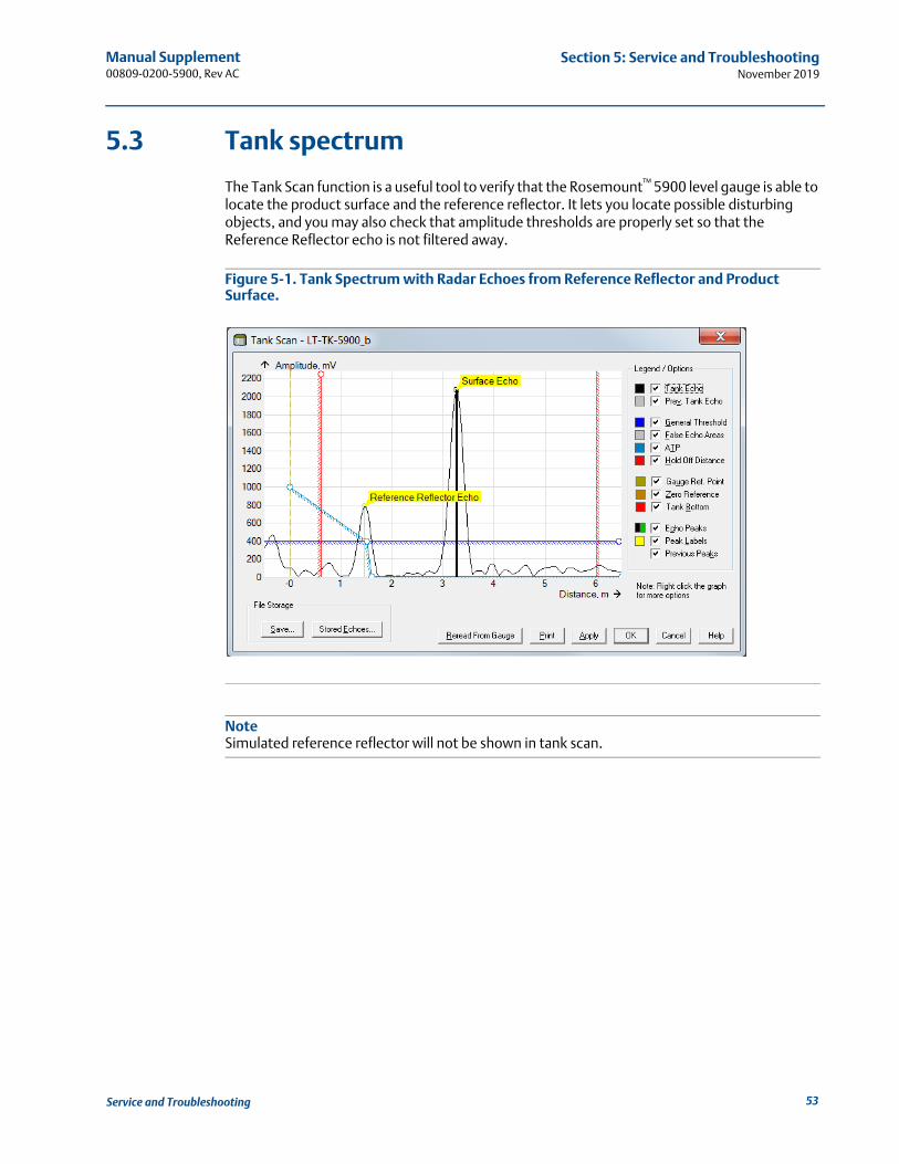
5.3 Tank spectrum
The Tank Scan function is a useful tool to verify that the Rosemount™ 5900 level gauge is able to locate the product surface and the reference reflector. It lets you locate possible disturbing objects, and you may also check that amplitude thresholds are properly set so that the Reference Reflector echo is not filtered away.
Figure 5-1. Tank Spectrum with Radar Echoes from Reference Reflector and Product Surface.
NoteSimulated reference reflector will not be shown in tank scan.
53Service and Troubleshooting
Manual Supplement00809-0200-5900, Rev AC
Section 5: Service and TroubleshootingNovember 2019
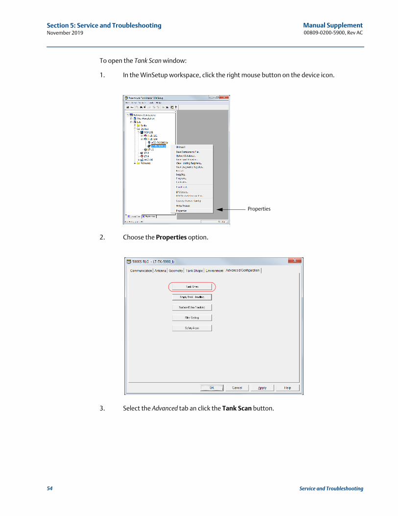
To open the Tank Scan window:
1. In the WinSetup workspace, click the right mouse button on the device icon.
2. Choose the Properties option.
3. Select the Advanced tab an click the Tank Scan button.
Properties
54 Service and Troubleshooting
Index-1
Manual Supplement 00809-0200-5900, Rev AC
IndexNovember 2019
Index
AAmplitude Factors . . . . . . . . . . . . . . . . . . . . . . . . . . . . . 36
CCalibrate button . . . . . . . . . . . . . . . . . . . . . . . . . . . . . . . 34Calibrate window . . . . . . . . . . . . . . . . . . . . . . . . . . . . . . 34Clamped tank connection . . . . . . . . . . . . . . . . . . . . . . . 17Clamping ring . . . . . . . . . . . . . . . . . . . . . . . . . . . . . . . . . 13Configuration . . . . . . . . . . . . . . . . . . . . . . . . . . . . . . . . . 29
DDistance Tolerance . . . . . . . . . . . . . . . . . . . . . . . . . . 34, 35
FFlexible Ring . . . . . . . . . . . . . . . . . . . . . . . . . . . . . . . . . . 25
HHistory . . . . . . . . . . . . . . . . . . . . . . . . . . . . . . . . . . . . . . 46
IInstallation . . . . . . . . . . . . . . . . . . . . . . . . . . . . . . . . . . . . 5Introduction . . . . . . . . . . . . . . . . . . . . . . . . . . . . . . . . . . . 1
MMax. Amplitude Factor . . . . . . . . . . . . . . . . . . . . . . . . . . 36Min. Amplitude Factor . . . . . . . . . . . . . . . . . . . . . . . . . . 36
OOperation . . . . . . . . . . . . . . . . . . . . . . . . . . . . . . . . . . . . 39
PProof Test Configuration window . . . . . . . . . . . . . . . . . 33
RReference Reflector . . . . . . . . . . . . . . . . . . . . . . . . . . . . 23
Parabolic Antenna. . . . . . . . . . . . . . . . . . . . . . . . . . 11Reference Reflector kit. . . . . . . . . . . . . . . . . . . . . . . . . . . .7Reminder . . . . . . . . . . . . . . . . . . . . . . . . . . . . . . . . . . . . 44RR Distance . . . . . . . . . . . . . . . . . . . . . . . . . . . . . . . 34, 35
SSafety Wire . . . . . . . . . . . . . . . . . . . . . . . . . . . . . . . . . . . 26Scheduling . . . . . . . . . . . . . . . . . . . . . . . . . . . . . . . . . . . 44Service Support . . . . . . . . . . . . . . . . . . . . . . . . . . . . . . . . .2Support. . . . . . . . . . . . . . . . . . . . . . . . . . . . . . . . . . . . . . . .2
TTank Geometry
Array Antenna. . . . . . . . . . . . . . . . . . . . . . . . . . . . . 20Parabolic Antenna. . . . . . . . . . . . . . . . . . . . . . . . . . . .9
Tolerance . . . . . . . . . . . . . . . . . . . . . . . . . . . . . . . . . . . . 36
WWelded tank connection . . . . . . . . . . . . . . . . . . . . . . . . 16Wire Distance . . . . . . . . . . . . . . . . . . . . . . . . . . . . . . 12, 15Wire Distance Calculation . . . . . . . . . . . . . . . . . . . . 15, 27
clamped tank connection. . . . . . . . . . . . . . . . . . . . 17Welded tank connection . . . . . . . . . . . . . . . . . . . . 16
Index

Index-2
Manual Supplement00809-0200-5900, Rev AC
IndexNovember 2019
Index

Manual Supplement00809-0200-5900, Rev AC
November 2019
Global Headquarters and Europe Regional Office
Tank GaugingEmerson Automation Solutions Box 150(Visiting address: Layoutvägen 1)SE-435 23 Mölnlycke+46 31 337 00 00+46 31 25 30 [email protected]
North America Regional OfficeTank GaugingEmerson Automation Solutions 6005 Rogerdale RoadMail Stop NC 136Houston TX 77072United States
+1 281 988 4000 or +1 800 722 [email protected]
Latin America Regional OfficeEmerson Automation Solutions 1300 Concord Terrace, Suite 400Sunrise, FL 33323, USA
+1 954 846 5030+1 954 846 [email protected]
Asia Pacific Regional OfficeEmerson Automation Solutions1 Pandan CrescentSingapore 128461
+65 6777 8211+65 6777 0947 [email protected]
Linkedin.com/company/Emerson-Process-Management
Twitter.com/Rosemount_News
Facebook.com/Rosemount
Youtube.com/user/RosemountMeasurement
Middle East and Africa Regional OfficeTank GaugingEmerson Automation Solutions P.O Box 20048ManamaBahrain
+973 1722 6610+973 1722 [email protected]
© 2019 Rosemount\ Inc. All rights reserved.
Emerson Terms and Conditions of Sale are available upon request. The Emerson logo is a trademark and service mark of Emerson Electric Co. Rosemount is a mark of one of the Emerson family of companies. All other marks are the property of their respective owners.