november 17, 2008 ilc08 hvac and ve update november 17, 2008 ilc cfs workshop 2008 chicago lee...
TRANSCRIPT

November 17, 2008 ILC08
HVAC and VE Update
November 17, 2008
ILC CFS Workshop 2008 Chicago
Lee Hammond, Fermilab
Global Design Effort

November 17,2008 ILC08 Global Design Effort 2
RDR to VE
• RDR - Air treatment Design Basis• Tunnel Ventilation – Conditioned dehumidified air from surface mounted
equipment is ducted into the service tunnel at each shaft. A volume of 25000m³/h (15000cfm) flows at approximately 27m/min (88fpm) to the midpoint between shafts where it is routed into the beam tunnel and returned to the shaft area. Fresh air at a rate of 20% (air change/16hr) is mixed into the air then conditioned and it is recirculated back to the service tunnel. Air volumes for the DR and BDS are similar.
• Hazardous Conditions - The air direction is reversible and capable of being doubled (unconditioned) during hazardous situations.
• Design temperature ML - The design temperature for the ML service and beam tunnels is 27-32°C (80-90°F). ML electronics' heat rejection is mainly to CHW direct cooling and FCUs with small amounts of heat to the ventilation air. AHU and FCUs are used at alcoves and shaft areas.
• Design temperature DR - The design temperature for the DR tunnel is 40°C (104°F), using process water fan coil units, and the tunnel wall as a heat rejection source.
November 17,2008 ILC08 Global Design Effort 3
RDR to VE
• RDR - Air treatment Design Basis• Design temperature BDS - The design temperature for the BDS is 29-32°C (85-
90°F). The low “heat to air” load is mainly absorbed by the tunnel wall. Air mixing fans will be used for temperature stability as required by the BDS.
• Used the basis that airflow could pass from the service tunnel to the beam tunnel through fire/smoke/ODH/radiation protected passages between the tunnels. This assumes that radiation/oxygen deficiency hazards (ODH) do not exist or can be mitigated between the tunnels from the standpoint of air mixing. This item needs concurrence from rad/ODH groups.
• AHU and FCU sizes in the alcoves and tunnels did not consider heat absorption by the rock wall. These units use chilled water from the surface as the heat rejection source.
November 17,2008 ILC08 Global Design Effort 4
RDR to VE
• Fan Coil Unit (FCU) rationalization• CHW Fan coil units are the most efficient way to pick up the large “heat load to
air” in the tunnel. • Heat loads to air were too great (at 26kw/RF at RDR then 21kw/RF post RDR
12/07) to be cooled solely by surface equipment. That’s 1-1.5MW in a 2.5km tunnel section.
• Stabilizes temperature gradients. • For example a 13mm (1/ 2”) pipe with CHW can remove 3.5kw of heat by
contrast it takes 250mm (10”) air duct. • At the upper limit of industry standard flowrates…to cool 1000kw (286tons)
requires 78m³/h (343gpm) or 272000m³/h (160000cfm). Either 100mm (4” pipe) or 3.7 m² (40sqft) duct…2.1m (7ft) diameter at 1200m/min (4000fpm)… 72km/hr (45mph)
• Eliminate CHW without greatly reducing the heat load…next step is to use Process water FCUs and/or compressorized self contained rack cooling equipment for heat rejection. This equipment requires approx 30°C (85°F) process water for heat rejetion.

November 17,2008 ILC08 Global Design Effort 5
HVAC VE Update
Analysis by W/MKW in
36m RFMaterial (K in W/m-
K)Temp in (F)
Tunnel Dia-m
Temp up to what radius
Ztang - Sep 2006 130 -4.68 Rock (4.6) 86 5 55F (25m)
Gbowden -Jul 2003 73 -2.63Earth, Sandstone, Conc (varies)
1133 77F (10m)
SSC TP/JT - Feb 1985 29 -1.04 Dolomite (3.5) 65 2.5? 55F (30m)A Enomoto - June 2008 100 -3.60
Not considered at this stage due to the small percentage of total load.
CHW Fan Coil Units are needed to maintain tunnel
temperatures.

6
Air System Concept
Shaft 7
Service tunnel
Beam tunnel
Approx 50-60 RF in 2.5kw section
Neutral air, 25000m³/h (15,000cfm)
30°C
30°C (85°F)
Fan coil Units

November 17,2008 ILC08 Global Design Effort 7
HVAC VE Update
• VE #1 – Investigate use of desiccant dehumidifiers • VE #2 – Modify top-of-shaft HVAC to only process
make up air, add blowers at tunnel level for recirculation
• VE #3 – Centralize the HVAC and reconfigure airflow from tunnel ends or center
• VE #4 – Utility built HI-efficiency cogen power/cooling plant on site and distribute power and 0.6°C (33°F) CHW throughout the facility
– Subpoint• Sub, sub point

November 17,2008 ILC08 Global Design Effort 8
HVAC VE Update
• VE item #1 – Investigate use of desiccant dehumidifiers • Desiccant dehumidifiers are efficient at providing very dry air. They are
designed to provide humidity levels much lower than required for the ILC tunnels. Preliminary investigation revealed the cost for this equipment to be in a range of twice the cost of refrigerant based dehumidification equipment. They also require higher energy use.
November 17,2008 ILC08 Global Design Effort 9
HVAC VE Update
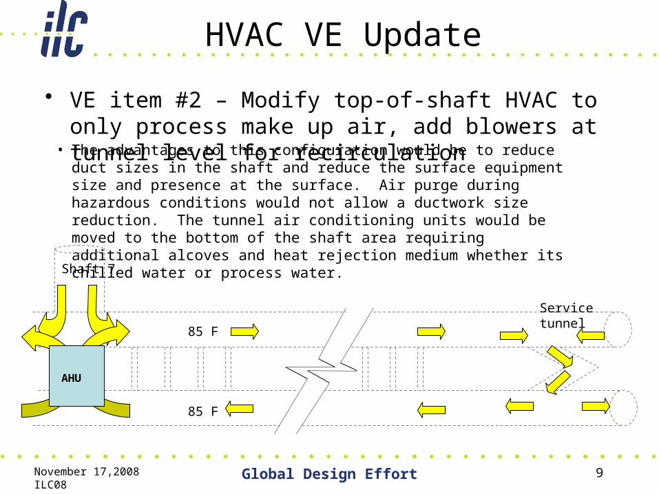
• VE item #2 – Modify top-of-shaft HVAC to only process make up air, add blowers at tunnel level for recirculation
• The advantages to this configuration would be to reduce duct sizes in the shaft and reduce the surface equipment size and presence at the surface. Air purge during hazardous conditions would not allow a ductwork size reduction. The tunnel air conditioning units would be moved to the bottom of the shaft area requiring additional alcoves and heat rejection medium whether its chilled water or process water.
Shaft 7
Service tunnel
85 F
85 F
AHU
November 17,2008 ILC08 Global Design Effort 10
HVAC VE Update
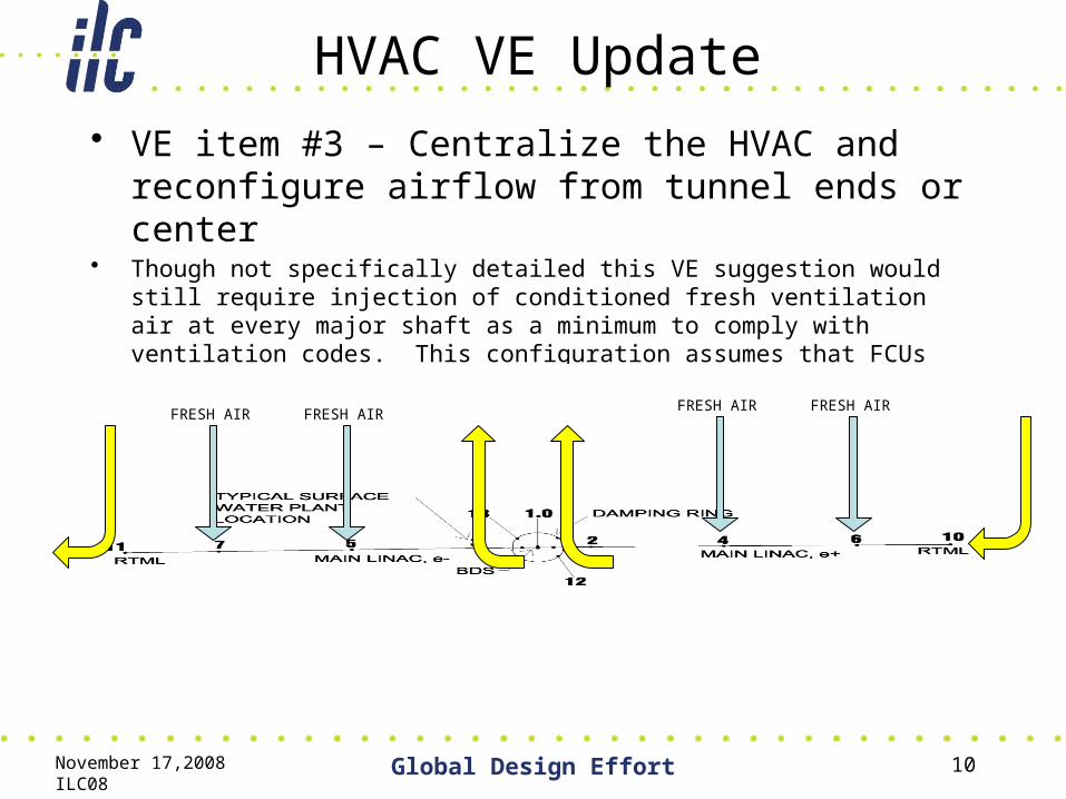
• VE item #3 – Centralize the HVAC and reconfigure airflow from tunnel ends or center
• Though not specifically detailed this VE suggestion would still require injection of conditioned fresh ventilation air at every major shaft as a minimum to comply with ventilation codes. This configuration assumes that FCUs and AHUs would be needed to condition the air for proper tunnel temperature.
FRESH AIR FRESH AIRFRESH AIR FRESH AIR
November 17,2008 ILC08 Global Design Effort 11
HVAC VE Update
• VE item #4 – Provide one hi-efficiency cogen power/cooling plant on site and distribute power and 0.6°C (33°F) CHW throughout the facility:
• Removes power/CHW production systems costs from the project cost.• Removes one piping system from project.• 0.6°C (33°F) CHW = smaller pipes, lower HP pumps, smaller HXs, very HI
delta T (50°C/90°F)• Cogen plant builder/operator finances, builds, operates, and maintains
power plant then sells utility power and CHW to ILC and possibly other customers.
• Allows cooling of tunnel and electronics mitigating high temperature disadvantages.
• Centralize plant reduces shaft/support area footprints

November 17,2008 ILC08 Global Design Effort 12
HVAC VE Update• Air Treatment is about 1% to 5.5% of CFS construction cost
estimate depending on where the CHW systems are located. If CHW is eliminated then the air refrigeration systems would be in the Air Treatment WBS.
RDR

November 17,2008 ILC08 Global Design Effort 13
HVAC VE Update
• Summary– Subpoint
• Sub, sub point

14
CFS Air Treatment Layout