novel pre-combustion capture technologies in action–results of the co2crc/hrl mulgrave capture...
TRANSCRIPT
GHGT-10
Novel Pre-Combustion Capture Technologies in Action – Results of the
CO2CRC/HRL Mulgrave Capture Project
Clare Andersona, Colin Scholes
a, Andrew Lee
b, Kathryn Smith
a, Sandra Kentish
a, Geoff Stevens
a,
Paul A. Webleyb, Abdul Qader
c and Barry Hooper
c
aDepartment of Chemical Biomolecular Engineering, The University of Melbourne, Victoria, Australia bDepartment of Chemical Engineering, Monash University (Clayton Campus), Victoria Australia
cCooperative Research Centre for Greenhouse Gas Technologies (CO2CRC)
Elsevier use only: Received date here; revised date here; accepted date here
Abstract
The Mulgrave capture project, which is funded under the Victorian Government’s Energy Technology Innovation Strategy
(ETIS) program, has the objective of demonstrating technologies designed to capture carbon dioxide (CO2) from synthesis gas
(syngas) produced from the air-blown gasification of brown coal. The technologies being investigated include solvent absorption,
membrane-based solvent absorption, membrane gas separation and gas adsorption.
Each technology was successful in demonstrating capture of CO2 from syngas during three separate campaigns, which were
completed from May 2009 until July 2010. The performance data and operational knowledge obtained from the Mulgrave
capture project will be central to future larger scale project work undertaken by the CO2CRC and partners.
© 2010 Elsevier Ltd. All rights reserved
Keywords:
c© 2011 Published by Elsevier Ltd.
Energy Procedia 4 (2011) 1192–1198
www.elsevier.com/locate/procedia
doi:10.1016/j.egypro.2011.01.173
1. Introduction
In June 2007, the Victorian State Government provided financial support, through their Energy Technology Innovative Strategy
(ETIS) program to the Cooperative Research Centre for Greenhouse Gas Technologies (CO2CRC) to deliver a three year
research program in pre-combustion capture. The CO2CRC was uniquely placed to deliver a comprehensive program, as it
includes research partners from a range of universities and is supported by a large number of industrial and government
organizations. The pre-combustion project specifically involves researchers from the University of Melbourne and from Monash
University, in addition to a process engineering design and fabrication contract company, Process Group, and the technology
development company, HRL Developments.
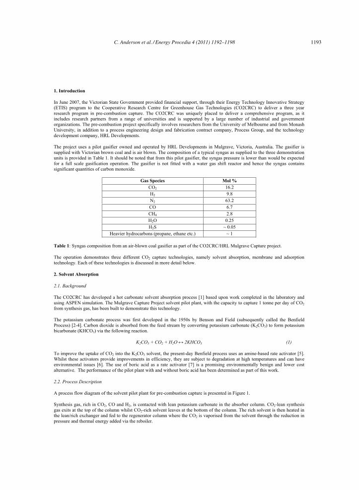
The project uses a pilot gasifier owned and operated by HRL Developments in Mulgrave, Victoria, Australia. The gasifier is
supplied with Victorian brown coal and is air blown. The composition of a typical syngas as supplied to the three demonstration
units is provided in Table 1. It should be noted that from this pilot gasifier, the syngas pressure is lower than would be expected
for a full scale gasification operation. The gasifier is not fitted with a water gas shift reactor and hence the syngas contains
significant quantities of carbon monoxide.
Gas Species Mol %
CO2 16.2
H2 9.8
N2 63.2
CO 6.7
CH4 2.8
H2O 0.25
H2S ~ 0.05
Heavier hydrocarbons (propane, ethane etc.) ~ 1
Table 1: Syngas composition from an air-blown coal gasifier as part of the CO2CRC/HRL Mulgrave Capture project.
The operation demonstrates three different CO2 capture technologies, namely solvent absorption, membrane and adsorption
technology. Each of these technologies is discussed in more detail below.
2. Solvent Absorption
2.1. Background
The CO2CRC has developed a hot carbonate solvent absorption process [1] based upon work completed in the laboratory and
using ASPEN simulation. The Mulgrave Capture Project solvent pilot plant, with the capacity to capture 1 tonne per day of CO2
from synthesis gas, has been built to demonstrate this technology.
The potassium carbonate process was first developed in the 1950s by Benson and Field (subsequently called the Benfield
Process) [2-4]. Carbon dioxide is absorbed from the feed stream by converting potassium carbonate (K2CO3) to form potassium
bicarbonate (KHCO3) via the following reaction.
K2CO3 + CO2 + H2O 2KHCO3 (1)
To improve the uptake of CO2 into the K2CO3 solvent, the present-day Benfield process uses an amine-based rate activator [5].
Whilst these activators provide improvements in efficiency, they are subject to degradation at high temperatures and can have
environmental issues [6]. The use of boric acid as a rate activator [7] is a promising environmentally benign and lower cost
alternative. The performance of the pilot plant with and without boric acid has been determined as part of this work.
2.2. Process Description
A process flow diagram of the solvent pilot plant for pre-combustion capture is presented in Figure 1.
Synthesis gas, rich in CO2, CO and H2, is contacted with lean potassium carbonate in the absorber column. CO2-lean synthesis
gas exits at the top of the column whilst CO2-rich solvent leaves at the bottom of the column. The rich solvent is then heated in
the lean/rich exchanger and fed to the regenerator column where the CO2 is vaporised from the solvent through the reduction in
pressure and thermal energy added via the reboiler.
C. Anderson et al. / Energy Procedia 4 (2011) 1192–1198 1193

The lean solvent is returned to the absorber via the lean/rich exchanger and lean solvent cooler. The regenerator overheads are
cooled in the condenser to recover water, which is recycled back to the regenerator via a reflux pump. The reflux drum overhead
vapour consists entirely of saturated CO2.
Syngas From Gasifier
300 kg/hr~ 15 vol% CO2
750 kPag55 to 70 C
AbsorberRegenerator
LG
CW
CW
LIC
TIC
LG
LCV
PCV CO2 to Incinerator30 kg/hr60 kPag
Lean Solvent1700 kg/hr
118 CRich Solvent1700 kg/hr
~ 100 C
PCV
Figure 1: Pre-combustion solvent pilot plant process flow diagram
2.3. Pilot Plant Performance
The performance of the solvent pilot plant during the three campaigns is summarised in Table 2.
CASE Promoter Syngas
Flowrate
Absorber
Temperature CO2 Removed
Reboiler
Energy Usage
kg/hr °C % MJ/kg CO2
Campaign 1 None 325 80 38% 8.2
Campaign 2 None 300 90 56% 6.4
Campaign 3 Boric Acid 300 95 56% 6.0
Table 2: Summary of results for the three campaigns of the Mulgrave Capture Project
Operation of the pilot plant was not optimised during the first campaign due to significant operational issues, such as solvent
precipitation and pump malfunction. Upon overcoming these issues during the second campaign, it was possible to optimise
process temperatures such that more CO2 was absorbed and the energy usage of the reboiler was reduced.
The addition of a rate-promoter, boric acid, to the solvent during the third campaign had little effect on increasing the amount of
CO2 absorbed and reducing the energy usage of the reboiler. The insignificant impact of the boric acid is thought to be because
the reaction rate is not limiting the absorption of CO2 at the high temperature of operation.
Heat losses to the environment from the pilot plant have been quantified at 1.5 MJ/kg CO2 and are a significant contributor to the
reboiler heating duty. Upon subtracting heat losses to the environment, the resulting reboiler energy usage is 4.5 to 4.9 MJ/kg
CO2, which is similar to values quoted for post-combustion capture [8]. At this stage no attempt was made to include heat
recovery strategies, which could significantly reduce the energy usage. Additionally, the CO2 removed was limited because of a
limit on the packing height in order to fit the vessel in the building. However, ASPEN simulation of the process provides a very
good match to the operating data.
1194 C. Anderson et al. / Energy Procedia 4 (2011) 1192–1198
2.4. Operating Knowledge
Practical knowledge of operating a solvent absorption process under real synthesis gas conditions was obtained during the three
campaigns. The most significant operating issues that were encountered during the operation of the pilot plant were (1) the
absorber water balance and (2) impurities absorbed into the solvent from the synthesis gas.
The balance of the water entering and exiting the absorber was determined by the water content of the synthesis feed gas and the
temperature of the absorber. As the temperature of the absorber increased, more water was removed in the exit gas. If the
synthesis gas is saturated or under-saturated with water, a net loss of water from the solvent will occur resulting in a more
concentrated solvent, a greater risk of bicarbonate precipitation and level control problems. Measurement of the feed gas water
concentration in particular enables the prediction of solvent water loss or gain. Appropriate management of the water balance,
such as the addition or removal of water from the reflux drum, was then undertaken to avoid level control problems.
The impurities absorbed into the solvent from the synthesis gas were liquid hydrocarbons and coal dust from a filter candle
failure. The liquid hydrocarbons slightly altered the physical properties of the solvent, such as surface tension but caused more
significant problems when combined with the coal dust to form larger sticky particles. In the absence of an inline solvent filtering
system, these sticky particles caused a range of operational issues such as pump strainer blockages and heat exchanger fouling.
3. Membranes
3.1. Background and Process Description
The CO2CRC/HRL Mulgrave membrane pilot plant is designed to separate 5.6 kg CO2 per day from H2 and N2 in syngas. The
small scale of the plant allows a range of membrane materials and membrane separation strategies to be trialed for separating
CO2. The pilot plant includes a pre-treatment section where the syngas is cooled to atmospheric temperature to remove
condensables and then re-heated to at least 35oC. Three membrane separation technologies can then be examined, polymeric gas
separation membranes, inorganic molecular sieve membranes and membrane gas absorption. The overall objective is to evaluate
a range of membrane materials and process designs, to determine those that will be the most success for pre-combustion capture
[9-10]. The pilot plant also provides the opportunity to test two gas separation membranes in series. This allows the possibility of
further purifying the CO2 from the retentate or permeate stream of the first membrane unit in the second membrane. The results
presented here are for a commercially available polysulfone based membrane hollow fiber module (Air Products PRISM©)
operating at 35oC.
3.2. Pilot Plant Performance
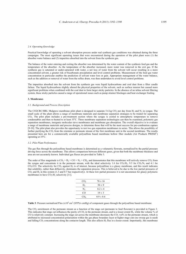
The gas flux through the polysulfone based membrane is determined as a volumetric flowrate, normalized by the partial pressure
driving force across the membrane. This allows comparison between different gases, given that both the membrane thickness and
area are not accurately known. Individual gas fluxes are provided in Table 3.
The order of flux magnitude is CO2 > H2 > CO > N2 > CH4, and demonstrates that this membrane will actively remove CO2 from
the syngas and concentrate it in the permeate stream, with the ideal selectivity 1.6 for CO2/H2, 9.5 for CO2/N2 and 4.1 for
CO2/CO. The selectivity for CO2 against H2 is of interest, because polysulfone is a glassy membrane, and this result indicates
that solubility, rather than diffusivity, dominates the separation process. This is believed to be due to the low partial pressures of
CO2 and H2 in this system (1.3 and 0.7 bar respectively). At these low partial pressures it is not uncommon for glassy polymeric
membranes to have CO2/H2 selectivity [11].
CO2 78 ± 16
H2 50 ± 9
N2 8.2 ± 4
CO 19 ± 3
CH4 0.9 ± 0.4
Table 3: Pressure normalized Flux (x105 cm3 (STP)/s cmHg) of component gases through the polysulfone based membrane.
The CO2 enrichment of the permeate stream as a function of the stage cut (permeate to feed flowrate) is provided in Figure 2.
This indicates that stage cut influences the purity of CO2 in the permeate stream, and to a lesser extent H2, while the volume % of
CO is relatively constant. Increasing the stage cut across the membrane decreases the CO2 vol% in the permeate stream, which is
attributed to increased concentration polarization within the gas phase boundary layer at higher stage cuts (no sweep gas is used)
and falling CO2 concentrations along the contactor length. This also affects H2 flux to a lesser extent. Importantly, this membrane
C. Anderson et al. / Energy Procedia 4 (2011) 1192–1198 1195

type is unable to purify carbon dioxide to the concentration required, and therefore additional multi-stage membrane separation is
needed. Other membrane types tested have proved more effective, with a maximum CO2/H2 selectivity of 7.4 and CO2/N2
selectivity of 25.7 recorded for a rubbery polymeric membrane at 50oC.
Figure 2: CO2/H2/N2/CO Vol % in the Permeate of the polysulfone based membrane as a function of stage cut.
3.3 Operating Knowledge
The principal learning from the membrane operation has been an understanding of the impact of minor components within the
syngas upon performance. Liquid hydrocarbons and coal dust have had less of an impact on the membrane unit than on the
solvent operation, possibly due to the use of a pre-treatment operation which has removed the majority of these components.
Conversely, we have often observed performance deterioration through exposure to high water partial pressures. The impact of
water, in combination with elevated operating temperatures has proved the most challenging problem. However, a number of
membranes have performed in spite of this challenging operation and these results will be presented in future papers.
4. Adsorption
4.1. Background
Various adsorbent materials such as zeolites [12], hydrotalcites [13], alumina [14] have been studied for capturing CO2 at
elevated temperature. In the Mulgrave adsorption project, the main objectives were : i) to evaluate the applicability of various
adsorbent materials for cyclic adsorption processes, ii) to identify engineering issues associated with the use of adsorption
technology on synthesis gas streams and iii) to optimise the process conditions to maximise CO2 capture performance under the
given operating conditions of the gasifier.
The Mulgrave Project included the construction of a fully automated cyclic adsorption gas separation apparatus that can operate
in either single-bed or dual-bed adsorption mode. A variety of cyclic processes can be conducted including PSA (pressure swing
adsorption), TSA (temperature swing adsorption), VSA (vacuum swing adsorption) and PVSA. The experimental setup can be
controlled for high temperature (up to 530 °C) and high pressure (up to 21 bar) conditions to represent conditions typical of large
scale IGCC applications.
4.2. Process Description
Two 1m long adsorption columns were packed with 200 grams of zeolite 13X in the centre of the column and both ends of the
column were packed with zeolite 3A to protect the adsorbents from contaminants including moisture. The adsorbents were
calcined before use.
Four different pressure vacuum swing adsorption (PVSA) processes were designed and performed in this study as shown in
Figure 3 below.
1196 C. Anderson et al. / Energy Procedia 4 (2011) 1192–1198

Figure 3. PVSA process designs used for adsorption research in the CO2CRC/HRL Mulgrave Project.
Adsorption is represented by AD, depressurisation by DP, de-adsorption by DE and re-pressurisation by RP. Pressure
equalisation (PE) and product purge (PP) operations were introduced to enhance the carbon capture performance in terms of CO2
concentration, recovery and energy consumption. Numerical simulation was used to anticipate the optimum experimental
conditions.
4.3. Pilot Plant Performance
The performance of the adsorption processes conducted at the gasifier on synthesis gas is summarised in Table 4. Syngas flow
rate was 0.37 kg/hr and syngas pressure was 0.72 MPa in all cases. Processes with pressure equalisation and product purge show
higher CO2 concentration. These results showed a trade-off between CO2 concentration and recovery.
CASE Absorber Temperature [CO2] CO2 Recovery
°C % %
A120 80.4 87.7
200 69.8 85.6
B120 96.0 84.4
200 94.1 81.9
C120 92.3 83.9
200 91.1 78.6
D120 98.1 72.2
200 98.2 72.8
Table 4: Summary of adsorption results from the CO2CRC.HRL Mulgrave Project. (* Simulation results)
Case D shows CO2 concentration at 200 °C (98.2 %) to be similar to that at 120 °C (98.1 %). This contrasts with case A in which
a considerable difference in CO2 concentration was found between 120 and 200°C. It is likely that the additional product purge
and pressure equalisation steps are able to compensate for differences in adsorbent selectivity which occur at 120 and 200°C. The
absence of these steps in process A magnifies the impact of the drop in adsorbent selectivity with increase in temperature.
C. Anderson et al. / Energy Procedia 4 (2011) 1192–1198 1197
Numerical simulation studies validated from our experimental results indicate that it is possible to produce 99% CO2 at 120 °C
under optimized process conditions. Engineering issues identified included presence of heavy hydrocarbons on the adsorbent as
well as trace amounts of sulphur. Adsorbent technology must be able to accommodate these impurities.
5. Conclusions
CO2 capture from pre-combustion synthesis gas has been successfully demonstrated using solvent absorption, membranes and
adsorbents. The data collected from the three campaigns is being used to create operating simulation models that will be used for
the design of larger scale facilities. The significant operating experience, particularly in dealing with impurities, gained during
the three campaigns will also be fundamental in the design of larger scale facilities.
6. Acknowledgments
The authors would like to thank HRL Developments and Process Group as partners in the project. Additionally, the authors
would like to acknowledge the funding provided by the Victorian State Government as part of ETIS and the funding provided by
the Australian Government through its CRC Program to support this research.
7. References
[1] B. Hooper, et al., "Plant and process for removing carbon dioxide from gas streams," United States of America Patent
Application 0317651 A1, 2008.
[2] H. E. Benson, et al., "Carbon Dioxide Absorption Employing Hot Potassium Carbonate Solutions," Chemical Engineering Progress, vol. 50, pp. 356-64, 1954.
[3] H. E. Benson, et al., "Improved Process for Carbon Dioxide Absorption uses Hot Carbonate Solutions," Chemical Engineering Progress, vol. 52, pp. 433-8, 1956.
[4] B. O. Buck and A. R. S. Leitch, "Try gas treating with hot carbonate," Petroleum Refiner, vol. 37, pp. 241-6, 1958.
[5] S. K. Furukawa and R. K. Bartoo, "Improved Benfield Process for Ammonia Plants," www.uop.com2003.
[6] R. Shao and A. Stangeland, "Amines Used in CO2 Capture - Health and Environmental Impacts," The Bellona
Foundation2009.
[7] U. K. Ghosh, et al., "Absorption of Carbon Dioxide into Aqueous Potassium Carbonate Promoted by Boric Acid," in
GHGT-9, Washington DC, USA, 2008.
[8] P. H. M. Feron, "The potential for improvement of the energy performance of pulverised coal fired power stations with
post-combsution capture of carbon dioxide," in GHGT-9, Washington DC, USA, 2008.
[9] C. A. Scholes, et al., "Membrane based carbon capture pilot plant trials," in AMS 5, Kobe, 2009.
[10] C. A. Scholes, et al., "The effect of condensable minor components on the gas separation performance of polymeric
membranes for carbon dioxide capture," Energy Procedia, vol. 1, pp. 311-317, 2009.
[11] W.-H. Lin and T.-S. Chung, "Gas permeability, diffusivity, solubility, and aging characteristics of 6FDA-durene
polyimide membranes," J. Membrane. Sci., vol. 186, pp. 183-193, 2001.
[12] R. V. Siriwardane, et al., "Adsorption of CO2 on zeolites at moderate temperatures," Energy and Fuels, vol. 19, pp.
1153-1159, 2005.
[13] Y. Ding and E. Alpay, "High temperature recovery of CO2 from flue gases using hydrotalcite adsorbents," Trans IChemE, vol. 79, pp. 45-51, 2001.
[14] Z. Yong, et al., "Adsorption of carbon dioxide on basic alumina at high temperatures," J. Chem. Eng. Data, vol. 45, pp.
1093-1095, 2000.
1198 C. Anderson et al. / Energy Procedia 4 (2011) 1192–1198