novel lead-free drape applied to the x-ray detector protects against scatter radiation in the...
TRANSCRIPT
CLINICAL STUDY
Novel Lead-Free Drape Applied to the X-Ray DetectorProtects against Scatter Radiation in the
Angiography Suite
Zubin Irani, MD, Bailin Alexander, BA, Da Zhang, PhD, Bob Liu, PhD,Brian Ghoshhajra, MD, and Rahmi Oklu, MD, PhD
ABSTRACT
Purpose: To evaluate a sterile, disposable lead-free drape for reducing scatter radiation exposure during fluoroscopy-guidedprocedures.
Materials and Methods: Computer-aided design software was used to model a procedure room with a thoracicanthropomorphic phantom on the angiography table. Using this model, measurements of scatter radiation were made fromthe phantom before and after the application of the drape using a collimated and full field of view in low-output conditions (70kVp, 48 mA) and high-output conditions (125 kVp, 156 mA). Transmission of x-rays through the drape and entrance exposurerates were also measured. Statistical significance was measured using a Student t test.
Results: Scatter radiation was attenuated throughout the procedure room when the drape was applied. The highest level ofscatter radiation was detected in the expected position of the operator, adjacent to the phantom. Radioprotection by the drapewas the greatest in this position: 71.5% attenuation at waist level and 89% at neck level (P o .0001). The use of the drape did notresult in an increase of backscatter radiation to the phantom.
Conclusions: The use of this drape significantly reduces scatter radiation in the procedure room; this effect is maximal in closeproximity to the phantom.
In the interventional suite, the protective garment and thethyroid shield comprise the primary means of radiationprotection for the body and neck. Other adjuncts includelead glasses, lead table skirts, lead drapes positioneddirectly over the patient, and stationary or ceiling moun-ted lead acrylic shields (1–4). Although each tool offersradioprotection to its user, some inherent limitations existwith each device. The protection provided by lead glassesis limited by deficiencies in lateral shielding and back-scatter from the user’s head (4,5). Ceiling-mounted shieldscan obstruct access to the patient, obstruct vision, andrequire frequent adjustment with movement of equipmentand changes in operator position. Radioprotective drapes
& SIR, 2014
J Vasc Interv Radiol 2014; 25:1200–1208
http://dx.doi.org/10.1016/j.jvir.2014.05.002
None of the authors have identified a conflict of interest.
From the Department of Imaging, Division of Interventional Radiology (Z.I., B.A.,R.O.); Department of Imaging, Division of Diagnostic Imaging Physics (D.Z.,B.L.); and Department of Imaging, Webster Center for Advanced Researchand Education in Radiation (D.Z., B.L., B.G.), Massachusetts General Hospital,55 Fruit Street, 290 Gray/Bigelow; and Harvard Medical School (Z.I., D.Z., B.L.,B.G., R.O.), Boston, MA 02114. Received September 1, 2013; final revisionreceived April 28, 2014; accepted May 2, 2014. Address correspondence to
R.O.; E-mail: [email protected]
laid over the patient can inadvertently increase exposure ifthey enter the measuring field of the fluoroscope. Perma-nent lead shields that attach to the x-ray detector areavailable; however, they are of limited value and seldomused especially when a sterile field must be maintained (2).In light of the health risks associated with low-level
radiation exposure in the angiography suite (6–8), othermeans to protect personnel from scatter radiation wereexplored. To this end, a sterile drape was designed thatcould be attached directly to the x-ray detector using ahook and loop fastener. This study reports the perform-ance of this drape under various fluoroscopic conditions,using a phantom in the angiography suite.
MATERIALS AND METHODS
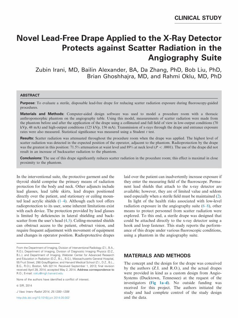
The concept and the design for the drape was conceivedby the authors (Z.I. and R.O.), and the actual drapeswere provided in kind as a custom design from Angio-Systems (Ducktown, Tennessee) at the request of theinvestigators (Fig 1a–d). No outside funding wasreceived for this project. The authors initiated thestudy and had complete control of the study designand the data.
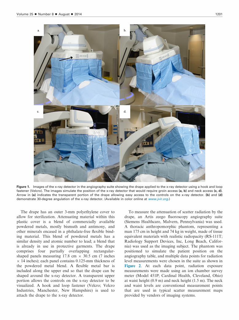
Figure 1. Images of the x-ray detector in the angiography suite showing the drape applied to the x-ray detector using a hook and loop
fastener (Velcro). The images simulate the position of the x-ray detector that would require groin access (a, b) and neck access (c, d).
Arrow in (a) indicates the transparent portion of the drape allowing easy access to the controls on the x-ray detector. (b) and (d)
demonstrate 30-degree angulation of the x-ray detector. (Available in color online at www.jvir.org.)
Volume 25 ’ Number 8 ’ August ’ 2014 1201
The drape has an outer 3-mm polyethylene cover toallow for sterilization. Attenuating material within thisplastic cover is a blend of commercially availablepowdered metals, mostly bismuth and antimony, andother minerals encased in a phthalate-free flexible bind-ing material. This blend of powdered metals has asimilar density and atomic number to lead; a blend thatis already in use in protective garments. The drapecomprises four partially overlapping rectangular-shaped panels measuring 17.8 cm � 30.5 cm (7 inches� 14 inches); each panel contains 0.125-mm thickness ofthe powdered metal blend. A flexible metal bar isincluded along the upper end so that the drape can beshaped around the x-ray detector. A transparent upperportion allows the controls on the x-ray detector to bevisualized. A hook and loop fastener (Velcro; VelcroIndustries, Manchester, New Hampshire) is used toattach the drape to the x-ray detector.
To measure the attenuation of scatter radiation by thedrape, an Artis zeego fluoroscopy angiography suite(Siemens Healthcare, Malvern, Pennsylvania) was used.A thoracic anthropomorphic phantom, representing aman 175 cm in height and 74 kg in weight, made of tissueequivalent materials with realistic radiopacity (RS-111T;Radiology Support Devices, Inc, Long Beach, Califor-nia) was used as the imaging subject. The phantom waspositioned to simulate the patient position on theangiography table, and multiple data points for radiationlevel measurements were chosen in the suite as shown inFigure 2. At each data point, radiation exposuremeasurements were made using an ion chamber surveymeter (Model 451P; Cardinal Health, Cleveland, Ohio)at waist height (0.9 m) and neck height (1.5 m). The neckand waist levels are conventional measurement pointsthat are used in typical scatter measurement mapsprovided by vendors of imaging systems.
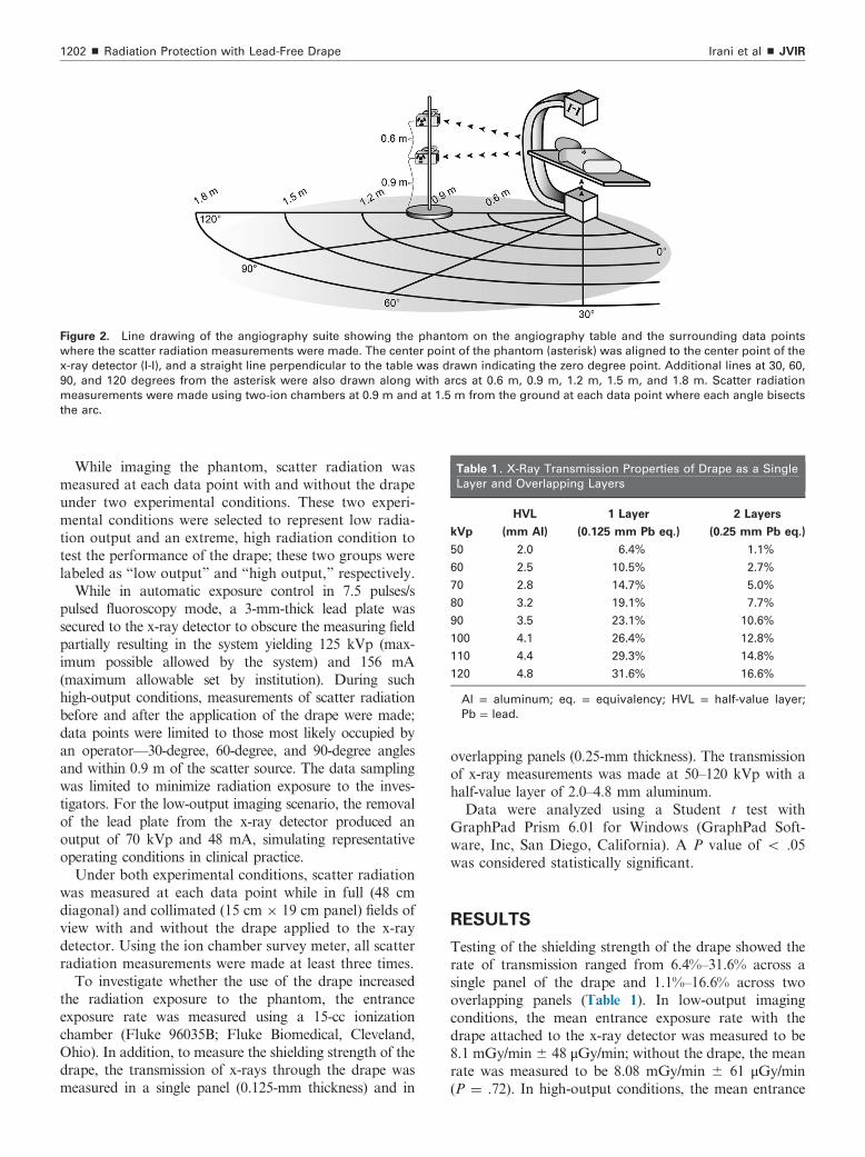
Figure 2. Line drawing of the angiography suite showing the phantom on the angiography table and the surrounding data points
where the scatter radiation measurements were made. The center point of the phantom (asterisk) was aligned to the center point of the
x-ray detector (I-I), and a straight line perpendicular to the table was drawn indicating the zero degree point. Additional lines at 30, 60,
90, and 120 degrees from the asterisk were also drawn along with arcs at 0.6 m, 0.9 m, 1.2 m, 1.5 m, and 1.8 m. Scatter radiation
measurements were made using two-ion chambers at 0.9 m and at 1.5 m from the ground at each data point where each angle bisects
the arc.
Table 1 . X-Ray Transmission Properties of Drape as a Single
Layer and Overlapping Layers
kVp
HVL
(mm Al)
1 Layer
(0.125 mm Pb eq.)
2 Layers
(0.25 mm Pb eq.)
50 2.0 6.4% 1.1%
60 2.5 10.5% 2.7%
70 2.8 14.7% 5.0%
80 3.2 19.1% 7.7%
90 3.5 23.1% 10.6%
100 4.1 26.4% 12.8%
110 4.4 29.3% 14.8%
120 4.8 31.6% 16.6%
Al = aluminum; eq. = equivalency; HVL = half-value layer;
Pb = lead.
Irani et al ’ JVIR1202 ’ Radiation Protection with Lead-Free Drape
While imaging the phantom, scatter radiation wasmeasured at each data point with and without the drapeunder two experimental conditions. These two experi-mental conditions were selected to represent low radia-tion output and an extreme, high radiation condition totest the performance of the drape; these two groups werelabeled as “low output” and “high output,” respectively.While in automatic exposure control in 7.5 pulses/s
pulsed fluoroscopy mode, a 3-mm-thick lead plate wassecured to the x-ray detector to obscure the measuring fieldpartially resulting in the system yielding 125 kVp (max-imum possible allowed by the system) and 156 mA(maximum allowable set by institution). During suchhigh-output conditions, measurements of scatter radiationbefore and after the application of the drape were made;data points were limited to those most likely occupied byan operator—30-degree, 60-degree, and 90-degree anglesand within 0.9 m of the scatter source. The data samplingwas limited to minimize radiation exposure to the inves-tigators. For the low-output imaging scenario, the removalof the lead plate from the x-ray detector produced anoutput of 70 kVp and 48 mA, simulating representativeoperating conditions in clinical practice.Under both experimental conditions, scatter radiation
was measured at each data point while in full (48 cmdiagonal) and collimated (15 cm � 19 cm panel) fields ofview with and without the drape applied to the x-raydetector. Using the ion chamber survey meter, all scatterradiation measurements were made at least three times.To investigate whether the use of the drape increased
the radiation exposure to the phantom, the entranceexposure rate was measured using a 15-cc ionizationchamber (Fluke 96035B; Fluke Biomedical, Cleveland,Ohio). In addition, to measure the shielding strength of thedrape, the transmission of x-rays through the drape wasmeasured in a single panel (0.125-mm thickness) and in
overlapping panels (0.25-mm thickness). The transmissionof x-ray measurements was made at 50–120 kVp with ahalf-value layer of 2.0–4.8 mm aluminum.Data were analyzed using a Student t test with
GraphPad Prism 6.01 for Windows (GraphPad Soft-ware, Inc, San Diego, California). A P value of o .05was considered statistically significant.
RESULTS
Testing of the shielding strength of the drape showed therate of transmission ranged from 6.4%–31.6% across asingle panel of the drape and 1.1%–16.6% across twooverlapping panels (Table 1). In low-output imagingconditions, the mean entrance exposure rate with thedrape attached to the x-ray detector was measured to be8.1 mGy/min� 48 μGy/min; without the drape, the meanrate was measured to be 8.08 mGy/min � 61 μGy/min(P ¼ .72). In high-output conditions, the mean entrance
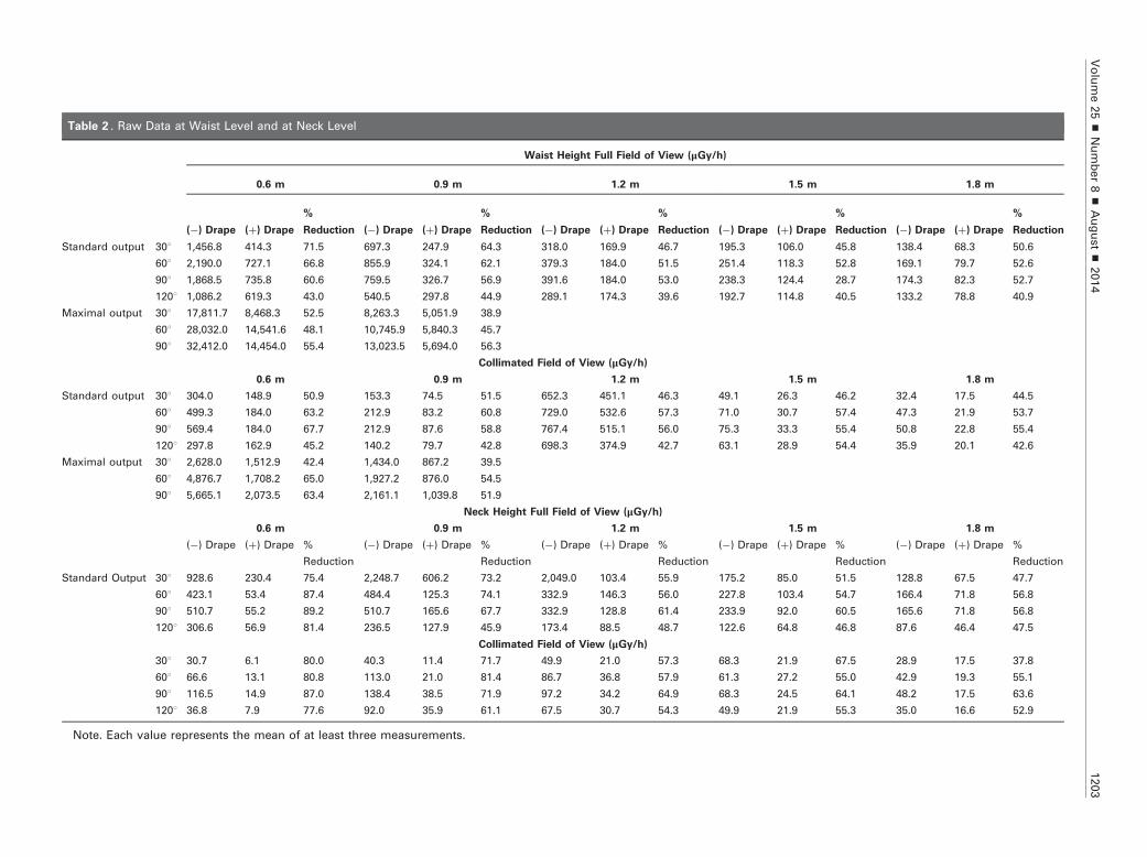
Table 2 . Raw Data at Waist Level and at Neck Level
Waist Height Full Field of View (μGy/h)
0.6 m 0.9 m 1.2 m 1.5 m 1.8 m
(�) Drape (þ) Drape
%
Reduction (�) Drape (þ) Drape
%
Reduction (�) Drape (þ) Drape
%
Reduction (�) Drape (þ) Drape
%
Reduction (�) Drape (þ) Drape
%
Reduction
Standard output 301 1,456.8 414.3 71.5 697.3 247.9 64.3 318.0 169.9 46.7 195.3 106.0 45.8 138.4 68.3 50.6
601 2,190.0 727.1 66.8 855.9 324.1 62.1 379.3 184.0 51.5 251.4 118.3 52.8 169.1 79.7 52.6
901 1,868.5 735.8 60.6 759.5 326.7 56.9 391.6 184.0 53.0 238.3 124.4 28.7 174.3 82.3 52.7
1201 1,086.2 619.3 43.0 540.5 297.8 44.9 289.1 174.3 39.6 192.7 114.8 40.5 133.2 78.8 40.9
Maximal output 301 17,811.7 8,468.3 52.5 8,263.3 5,051.9 38.9
601 28,032.0 14,541.6 48.1 10,745.9 5,840.3 45.7
901 32,412.0 14,454.0 55.4 13,023.5 5,694.0 56.3
Collimated Field of View (μGy/h)
0.6 m 0.9 m 1.2 m 1.5 m 1.8 m
Standard output 301 304.0 148.9 50.9 153.3 74.5 51.5 652.3 451.1 46.3 49.1 26.3 46.2 32.4 17.5 44.5
601 499.3 184.0 63.2 212.9 83.2 60.8 729.0 532.6 57.3 71.0 30.7 57.4 47.3 21.9 53.7
901 569.4 184.0 67.7 212.9 87.6 58.8 767.4 515.1 56.0 75.3 33.3 55.4 50.8 22.8 55.4
1201 297.8 162.9 45.2 140.2 79.7 42.8 698.3 374.9 42.7 63.1 28.9 54.4 35.9 20.1 42.6
Maximal output 301 2,628.0 1,512.9 42.4 1,434.0 867.2 39.5
601 4,876.7 1,708.2 65.0 1,927.2 876.0 54.5
901 5,665.1 2,073.5 63.4 2,161.1 1,039.8 51.9
Neck Height Full Field of View (μGy/h)
0.6 m 0.9 m 1.2 m 1.5 m 1.8 m
(�) Drape (þ) Drape %
Reduction
(�) Drape (þ) Drape %
Reduction
(�) Drape (þ) Drape %
Reduction
(�) Drape (þ) Drape %
Reduction
(�) Drape (þ) Drape %
Reduction
Standard Output 301 928.6 230.4 75.4 2,248.7 606.2 73.2 2,049.0 103.4 55.9 175.2 85.0 51.5 128.8 67.5 47.7
601 423.1 53.4 87.4 484.4 125.3 74.1 332.9 146.3 56.0 227.8 103.4 54.7 166.4 71.8 56.8
901 510.7 55.2 89.2 510.7 165.6 67.7 332.9 128.8 61.4 233.9 92.0 60.5 165.6 71.8 56.8
1201 306.6 56.9 81.4 236.5 127.9 45.9 173.4 88.5 48.7 122.6 64.8 46.8 87.6 46.4 47.5
Collimated Field of View (μGy/h)
301 30.7 6.1 80.0 40.3 11.4 71.7 49.9 21.0 57.3 68.3 21.9 67.5 28.9 17.5 37.8
601 66.6 13.1 80.8 113.0 21.0 81.4 86.7 36.8 57.9 61.3 27.2 55.0 42.9 19.3 55.1
901 116.5 14.9 87.0 138.4 38.5 71.9 97.2 34.2 64.9 68.3 24.5 64.1 48.2 17.5 63.6
1201 36.8 7.9 77.6 92.0 35.9 61.1 67.5 30.7 54.3 49.9 21.9 55.3 35.0 16.6 52.9
Note. Each value represents the mean of at least three measurements.
Volume25
’Number8
’August’
2014
1203
Irani et al ’ JVIR1204 ’ Radiation Protection with Lead-Free Drape
exposure rate with the drape was measured to be 53 mGy/min � 52 μGy/min; without the drape, the mean rate wasmeasured to be 53.4 mGy/min � 31 μGy/min (P ¼ .75).The application of the drape resulted in marked
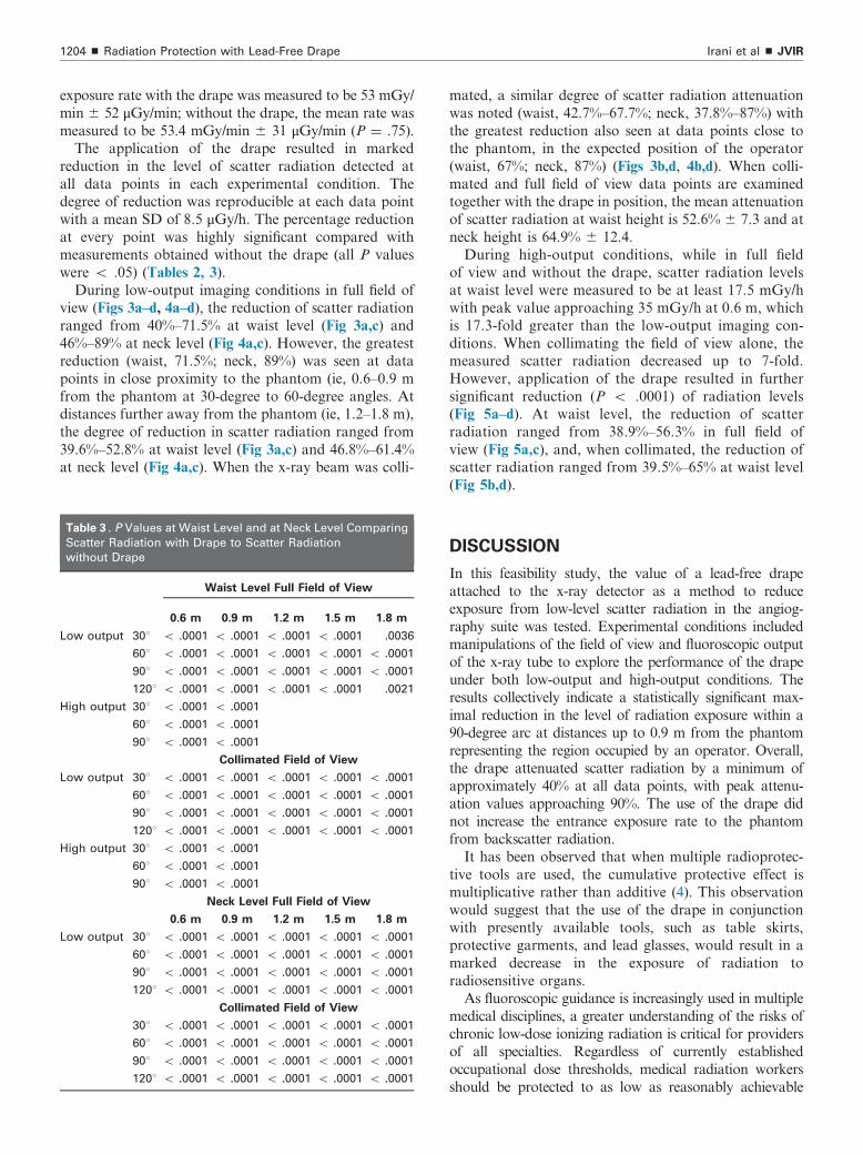
reduction in the level of scatter radiation detected atall data points in each experimental condition. Thedegree of reduction was reproducible at each data pointwith a mean SD of 8.5 μGy/h. The percentage reductionat every point was highly significant compared withmeasurements obtained without the drape (all P valueswere o .05) (Tables 2, 3).During low-output imaging conditions in full field of
view (Figs 3a–d, 4a–d), the reduction of scatter radiationranged from 40%–71.5% at waist level (Fig 3a,c) and46%–89% at neck level (Fig 4a,c). However, the greatestreduction (waist, 71.5%; neck, 89%) was seen at datapoints in close proximity to the phantom (ie, 0.6–0.9 mfrom the phantom at 30-degree to 60-degree angles. Atdistances further away from the phantom (ie, 1.2–1.8 m),the degree of reduction in scatter radiation ranged from39.6%–52.8% at waist level (Fig 3a,c) and 46.8%–61.4%at neck level (Fig 4a,c). When the x-ray beam was colli-
Table 3 . P Values at Waist Level and at Neck Level Comparing
Scatter Radiation with Drape to Scatter Radiation
without Drape
Waist Level Full Field of View
0.6 m 0.9 m 1.2 m 1.5 m 1.8 m
Low output 301 o .0001 o .0001 o .0001 o .0001 .0036
601 o .0001 o .0001 o .0001 o .0001 o .0001
901 o .0001 o .0001 o .0001 o .0001 o .0001
1201 o .0001 o .0001 o .0001 o .0001 .0021
High output 301 o .0001 o .0001
601 o .0001 o .0001
901 o .0001 o .0001
Collimated Field of View
Low output 301 o .0001 o .0001 o .0001 o .0001 o .0001
601 o .0001 o .0001 o .0001 o .0001 o .0001
901 o .0001 o .0001 o .0001 o .0001 o .0001
1201 o .0001 o .0001 o .0001 o .0001 o .0001
High output 301 o .0001 o .0001
601 o .0001 o .0001
901 o .0001 o .0001
Neck Level Full Field of View
0.6 m 0.9 m 1.2 m 1.5 m 1.8 m
Low output 301 o .0001 o .0001 o .0001 o .0001 o .0001
601 o .0001 o .0001 o .0001 o .0001 o .0001
901 o .0001 o .0001 o .0001 o .0001 o .0001
1201 o .0001 o .0001 o .0001 o .0001 o .0001
Collimated Field of View
301 o .0001 o .0001 o .0001 o .0001 o .0001
601 o .0001 o .0001 o .0001 o .0001 o .0001
901 o .0001 o .0001 o .0001 o .0001 o .0001
1201 o .0001 o .0001 o .0001 o .0001 o .0001
mated, a similar degree of scatter radiation attenuationwas noted (waist, 42.7%–67.7%; neck, 37.8%–87%) withthe greatest reduction also seen at data points close tothe phantom, in the expected position of the operator(waist, 67%; neck, 87%) (Figs 3b,d, 4b,d). When colli-mated and full field of view data points are examinedtogether with the drape in position, the mean attenuationof scatter radiation at waist height is 52.6% � 7.3 and atneck height is 64.9% � 12.4.During high-output conditions, while in full field
of view and without the drape, scatter radiation levelsat waist level were measured to be at least 17.5 mGy/hwith peak value approaching 35 mGy/h at 0.6 m, whichis 17.3-fold greater than the low-output imaging con-ditions. When collimating the field of view alone, themeasured scatter radiation decreased up to 7-fold.However, application of the drape resulted in furthersignificant reduction (P o .0001) of radiation levels(Fig 5a–d). At waist level, the reduction of scatterradiation ranged from 38.9%–56.3% in full field ofview (Fig 5a,c), and, when collimated, the reduction ofscatter radiation ranged from 39.5%–65% at waist level(Fig 5b,d).
DISCUSSION
In this feasibility study, the value of a lead-free drapeattached to the x-ray detector as a method to reduceexposure from low-level scatter radiation in the angiog-raphy suite was tested. Experimental conditions includedmanipulations of the field of view and fluoroscopic outputof the x-ray tube to explore the performance of the drapeunder both low-output and high-output conditions. Theresults collectively indicate a statistically significant max-imal reduction in the level of radiation exposure within a90-degree arc at distances up to 0.9 m from the phantomrepresenting the region occupied by an operator. Overall,the drape attenuated scatter radiation by a minimum ofapproximately 40% at all data points, with peak attenu-ation values approaching 90%. The use of the drape didnot increase the entrance exposure rate to the phantomfrom backscatter radiation.It has been observed that when multiple radioprotec-
tive tools are used, the cumulative protective effect ismultiplicative rather than additive (4). This observationwould suggest that the use of the drape in conjunctionwith presently available tools, such as table skirts,protective garments, and lead glasses, would result in amarked decrease in the exposure of radiation toradiosensitive organs.As fluoroscopic guidance is increasingly used in multiple
medical disciplines, a greater understanding of the risks ofchronic low-dose ionizing radiation is critical for providersof all specialties. Regardless of currently establishedoccupational dose thresholds, medical radiation workersshould be protected to as low as reasonably achievable
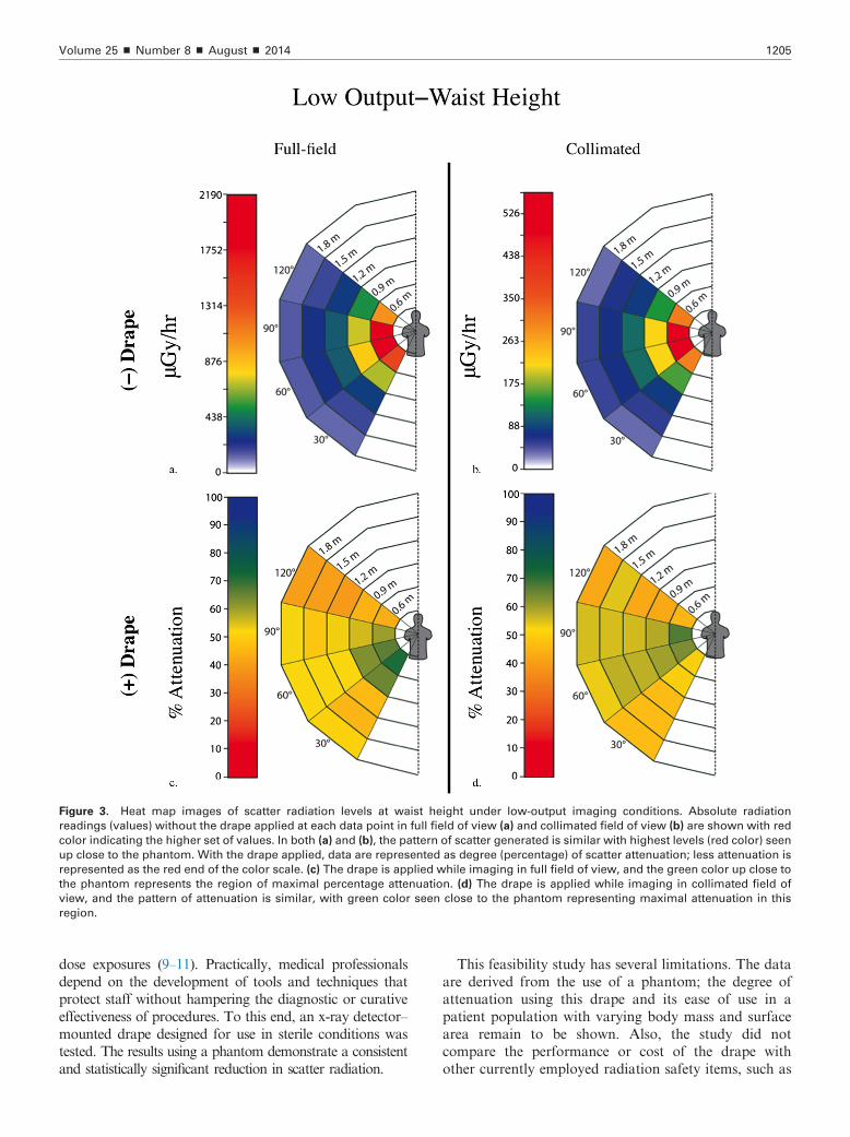
Figure 3. Heat map images of scatter radiation levels at waist height under low-output imaging conditions. Absolute radiation
readings (values) without the drape applied at each data point in full field of view (a) and collimated field of view (b) are shown with red
color indicating the higher set of values. In both (a) and (b), the pattern of scatter generated is similar with highest levels (red color) seen
up close to the phantom. With the drape applied, data are represented as degree (percentage) of scatter attenuation; less attenuation is
represented as the red end of the color scale. (c) The drape is applied while imaging in full field of view, and the green color up close to
the phantom represents the region of maximal percentage attenuation. (d) The drape is applied while imaging in collimated field of
view, and the pattern of attenuation is similar, with green color seen close to the phantom representing maximal attenuation in this
region.
Volume 25 ’ Number 8 ’ August ’ 2014 1205
dose exposures (9–11). Practically, medical professionalsdepend on the development of tools and techniques thatprotect staff without hampering the diagnostic or curativeeffectiveness of procedures. To this end, an x-ray detector–mounted drape designed for use in sterile conditions wastested. The results using a phantom demonstrate a consistentand statistically significant reduction in scatter radiation.
This feasibility study has several limitations. The dataare derived from the use of a phantom; the degree ofattenuation using this drape and its ease of use in apatient population with varying body mass and surfacearea remain to be shown. Also, the study did notcompare the performance or cost of the drape withother currently employed radiation safety items, such as
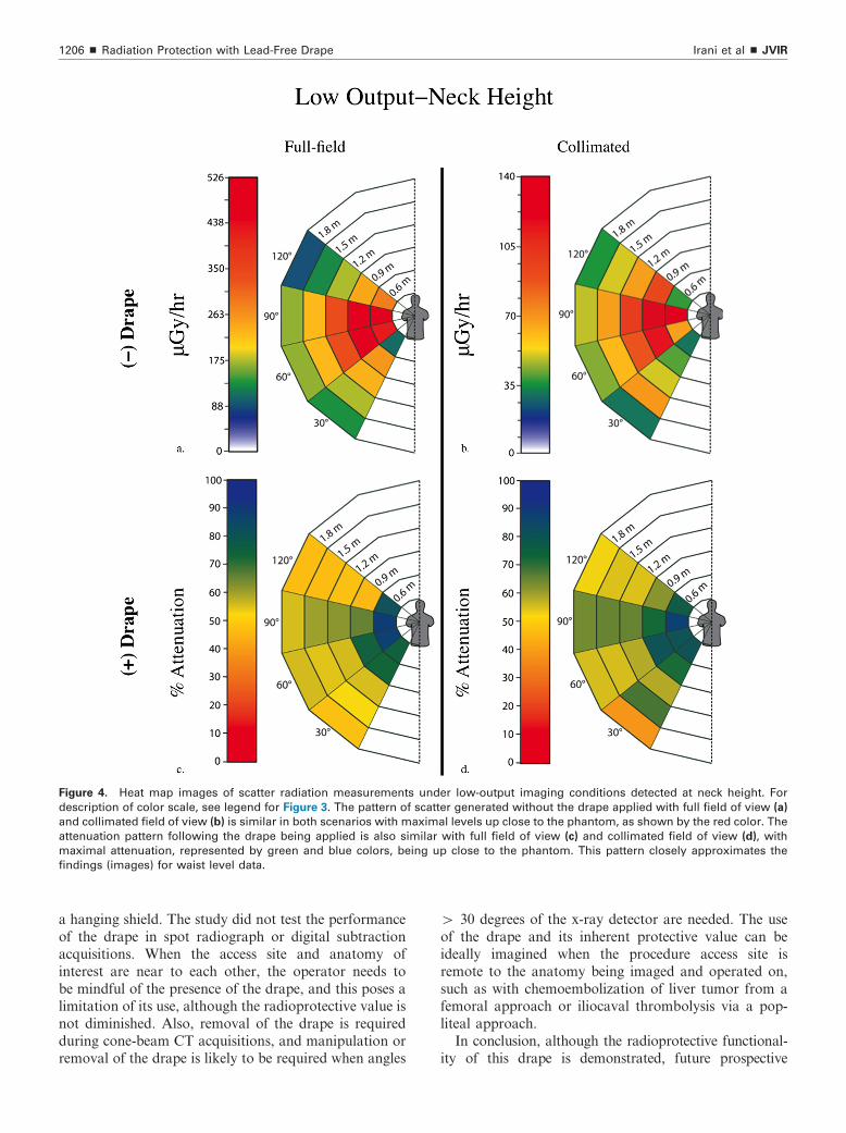
Figure 4. Heat map images of scatter radiation measurements under low-output imaging conditions detected at neck height. For
description of color scale, see legend for Figure 3. The pattern of scatter generated without the drape applied with full field of view (a)
and collimated field of view (b) is similar in both scenarios with maximal levels up close to the phantom, as shown by the red color. The
attenuation pattern following the drape being applied is also similar with full field of view (c) and collimated field of view (d), with
maximal attenuation, represented by green and blue colors, being up close to the phantom. This pattern closely approximates the
findings (images) for waist level data.
Irani et al ’ JVIR1206 ’ Radiation Protection with Lead-Free Drape
a hanging shield. The study did not test the performanceof the drape in spot radiograph or digital subtractionacquisitions. When the access site and anatomy ofinterest are near to each other, the operator needs tobe mindful of the presence of the drape, and this poses alimitation of its use, although the radioprotective value isnot diminished. Also, removal of the drape is requiredduring cone-beam CT acquisitions, and manipulation orremoval of the drape is likely to be required when angles
4 30 degrees of the x-ray detector are needed. The useof the drape and its inherent protective value can beideally imagined when the procedure access site isremote to the anatomy being imaged and operated on,such as with chemoembolization of liver tumor from afemoral approach or iliocaval thrombolysis via a pop-liteal approach.In conclusion, although the radioprotective functional-
ity of this drape is demonstrated, future prospective
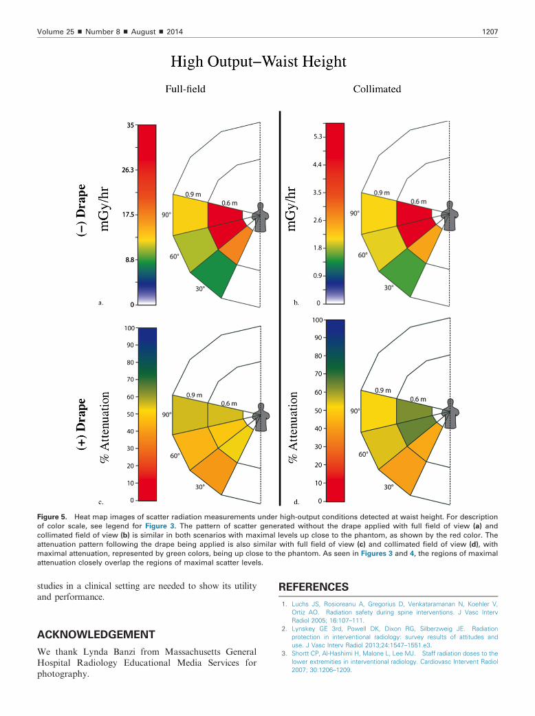
Figure 5. Heat map images of scatter radiation measurements under high-output conditions detected at waist height. For description
of color scale, see legend for Figure 3. The pattern of scatter generated without the drape applied with full field of view (a) and
collimated field of view (b) is similar in both scenarios with maximal levels up close to the phantom, as shown by the red color. The
attenuation pattern following the drape being applied is also similar with full field of view (c) and collimated field of view (d), with
maximal attenuation, represented by green colors, being up close to the phantom. As seen in Figures 3 and 4, the regions of maximal
attenuation closely overlap the regions of maximal scatter levels.
Volume 25 ’ Number 8 ’ August ’ 2014 1207
studies in a clinical setting are needed to show its utilityand performance.
ACKNOWLEDGEMENT
We thank Lynda Banzi from Massachusetts GeneralHospital Radiology Educational Media Services forphotography.
REFERENCES
1. Luchs JS, Rosioreanu A, Gregorius D, Venkataramanan N, Koehler V,Ortiz AO. Radiation safety during spine interventions. J Vasc IntervRadiol 2005; 16:107–111.
2. Lynskey GE 3rd, Powell DK, Dixon RG, Silberzweig JE. Radiationprotection in interventional radiology: survey results of attitudes anduse. J Vasc Interv Radiol 2013;24:1547–1551.e3.
3. Shortt CP, Al-Hashimi H, Malone L, Lee MJ. Staff radiation doses to thelower extremities in interventional radiology. Cardiovasc Intervent Radiol2007; 30:1206–1209.

Irani et al ’ JVIR1208 ’ Radiation Protection with Lead-Free Drape
4. Thornton RH, Dauer LT, Altamirano JP, Alvarado KJ, St Germain J, SolomonSB. Comparing strategies for operator eye protection in the interventionalradiology suite. J Vasc Interv Radiol 2010; 21:1703–1707.
5. Moore WE, Ferguson G, Rohrmann C. Physical factors determining theutility of radiation safety glasses. Med Phys 1980; 7:8–12.
6. Committee to Assess Health Risks from Exposure to Low Levels ofIonizing Radiation NRC. Health Risks from Exposure to Low Levels ofIonizing Radiation: BEIR VII Phase 2. Washington, DC: The NationalAcademies Press; 2006.
7. Darby SC, Cutter DJ, Boerma M, et al. Radiation-related heart disease:current knowledge and future prospects. Int J Radiat Oncol Biol Phys2010; 76:656–665.
8. Picano E, Vano E, Domenici L, Bottai M, Thierry-Chef I. Cancer and non-cancer brain and eye effects of chronic low-dose ionizing radiationexposure. BMC Cancer 2012; 12:157.
9. Cousins C, Sharp C. Medical interventional procedures—reducing theradiation risks. Clin Radiol 2004; 59:468–473.
10. Vehmas T. Radiation exposure during standard and complex interven-tional procedures. Br J Radiol 1997; 70:296–298.
11. Walker TG, Kalva SP, Ganguli S, et al. Image optimization duringendovascular aneurysm repair. AJR Am J Roentgenol 2012; 198:200–206.