novel branching-router-based multicast routing protocol with mobility support
TRANSCRIPT

Novel Branching-Router-Based MulticastRouting Protocol with Mobility Support
Zhiwei Yan, Jong-Hyouk Lee, Senior Member, IEEE,
Sean Shen, and Chunming Qiao, Fellow, IEEE
Abstract—To cope with challenging problems faced by traditional multicast routing protocols, many branching-router (BR)-based
multicast routing schemes with desirable features have been proposed. However, the current BR-based methods still lack efficient
multicast management and suffer from a long join latency, leading to a disappointing mobility performance. In this paper, we propose a
novel BR-based multicast architecture with a corresponding multicast routing protocol supporting multicast receiver mobility. In the
proposed multicast architecture, a new management entity called multicast controller (MC) is used to handle most of the multicast
management-related tasks, while other routers in the network construct a multicast tree according to the proposed Branching-Router-
based Multicast routing protocol with Mobility support (BRMM). Besides, the fast handover of multicast service can be supported by
BRMM through the pre-establishment of temporary multicast paths. Through extensive simulation and analysis, we show that BRMM
outperforms existing protocols and has many other attractive features.
Index Terms—Multicast, mobility, branching router
Ç
1 INTRODUCTION
MULTICAST is a term associated with the networksupport for efficient data delivery to multiple inter-
ested recipients. Its service model is defined as follows: LetH be the set of all IP hosts and EG be a subset of H, set EG
forms a multicast group with a group identifier known asits address G, if and only if:
. members of H may join and leave EG at any time;
. members of H can communicate unidirectionallywith all members of EG, using only G. Thisrequirement suggests that a host does not need tobe a member of a multicast group to send data tothat particular group.
Efficient multicast places the least amount of burden on
network and end-host resources when compared with other
methods to disseminate data to a group of recipients. The
demand for multicast communication from networking
applications has been growing at an accelerated pace. For
instance, video conferencing, online gaming, software dis-
tribution, and so on, can all benefit from multicast.With traditional multicast routing protocols, a router on a
multicast tree maintains forwarding-state information for
a multicast group to determine how to forward multicastpackets for the group, even if it is not a member router. Sincea router may be on multiple multicast trees and theforwarding-state information for each multicast group mayoften change as well, scalability problem is a serious concern.
To reduce forwarding states at non-branching routers(non-BRs) and to address the scalability problem oftraditional multicast routing protocols, several BR-basedschemes have been proposed [1], [2], [3], [4] (their detaileddescriptions can be found in Appendix A, which can befound on the Computer Society Digital Library at http://doi.ieeecomputersociety.org/10.1109/TPDS.2012.305).A common goal of such schemes is to release someintermediate routers from maintaining multicast relatedstates. Then, a multicast tree is identified by its branchingpoints, and data are delivered from one branching point toanother using native unicast routing protocols. The mainmotivation here is that in a typical sparse multicast tree, themajority of routers are relay routers that forward incomingpackets to the same outgoing interface. In the BR-basedprotocols, only BRs keep multicast forwarding table (MFT)entries and all non-BRs forward multicast data packets useunicast forwarding. As a result, these protocols require lessmemory than the traditional approaches. The BR-basedmulticast has many other important features such asincremental deployability, high tree availability, no needfor domain-wide address allocation mechanisms, possibilityof performing access control at a sender’s site, and treeconstruction in the forwarding direction. Among them,incremental deployability is a vital feature. More specifi-cally, traditional multicast routing protocols require everyrouter in the network to implement the protocol function-alities. In contrast, BR-based protocols have native supportfor incremental deployment. Since all packets have unicastdestination addresses, routers that do not implement theprotocol will forward the packets in unicast manner. In
2060 IEEE TRANSACTIONS ON PARALLEL AND DISTRIBUTED SYSTEMS, VOL. 24, NO. 10, OCTOBER 2013
. Z. Yan and S. Shen are with the China Internet Network InformationCenter, Computer Network Information Center, Chinese Academy ofSciences, Beijing 100190, P.R. China.E-mail: {yanzhiwei, shenshuo}@cnnic.cn.
. J.-H. Lee is with the Department of Computer Software Engineering,Sangmyung University, Cheonan, 330-720, Republic of Korea.E-mail: [email protected].
. C. Qiao is with the Department of Computer Science and Engineering,State University of New York at Buffalo, Buffalo, NY 14260-2000.E-mail: [email protected].
Manuscript received 30 June 2012; revised 29 Sept. 2012; accepted 5 Oct.2012; published online 19 Oct. 2012.Recommended for acceptance by A. Kshemkalyani.For information on obtaining reprints of this article, please send e-mail to:[email protected], and reference IEEECS Log Number TPDS-2012-06-0608.Digital Object Identifier no. 10.1109/TPDS.2012.305.
1045-9219/13/$31.00 � 2013 IEEE Published by the IEEE Computer Society
other words, although a router cannot act as a BR, it still can
take part in multicast data distribution.Although the BR-based multicast protocols outperform
the conventional multicast approaches in many aspects,
several challenges are still open. By building upon the prior
work, a comprehensive and novel multicast architecture is
proposed in this paper to improve the multicast efficiency,
management, mobility, and so on. In the proposed multi-
cast architecture, a multicast controller (MC) is deployed
for multicast management. It uses multicast identifiers
(MIs) that contain more information than the traditional
multicast IP addresses. Based on this multicast architecture,
the Branching-Router-based Multicast routing protocol
with Mobility support (BRMM) is also proposed. In
BRMM, four types of signaling messages are used to
establish and maintain the shortest path tree (SPT) of the
multicast routing. To speed up the multicast join process
and support the fast mobility of multicast receivers, a
temporary state is used to immediately transmit the
multicast packets to the receiver once its handover is
finished. From simulation and analysis results, we find that
our proposed BRMM outperforms other existing protocols
from many aspects and thus is a promising scheme for
both fixed and mobile multicast services.The rest of this paper is organized as follows: In Section 2,
the proposed BR-based multicast architecture and protocol
are presented. Then, in Section 3, simulation results are
presented in which BRMM is compared with NBM and
SEM. Section 4 concludes this paper. Note that the
supplement of this paper contains the following: 1) related
work on the existing IP multicast routing protocols and
schemes in Appendix A, available in the online supple-
mental material; 2) examples of BRMM’s multicast tree
construction and maintenance in Appendix B, available in
the online supplemental material; and 3) performance
metric analysis in Appendix C, available in the online
supplemental material.
2 BRANCHING-ROUTER-BASED MULTICAST
ROUTING PROTOCOL WITH MOBILITY SUPPORT
In this section, we first describe our design requirements
of BRMM and then present its architecture and operations
in detail.
2.1 Requirements
The proposed BRMM fulfills the following requirements:
. Fast join and leave: The receiver who wants to enjoythe multicast service and the receiver who movesduring the multicast session could receive themulticast packets as soon as possible. Besides, therouter should immediately stop sending packets tothe receiver who wants to leave the multicast group.
. Minimize the signaling cost: To construct and maintainthe multicast tree, the signaling messages arenecessary. However, the signaling message ex-change should be simple and the cost should be aslow as possible.
. Efficient packet transmission: Packets have unicastdestination addresses. The routers that only act asBRs for a specific group are responsible for creatingpacket copies with modified destination addresses.Besides, the multicast packets should be transmittedthrough the SPT from the source to the receiver.
. Comprehensive multicast management: Strict multicastsource and receiver management and multicastquality of service (QoS) can be easily deployed. Inthis way, the direction and scope of multicast datapropagation can be controllable as far as the largenumber of multicast data is concerned.
2.2 Multicast Architecture
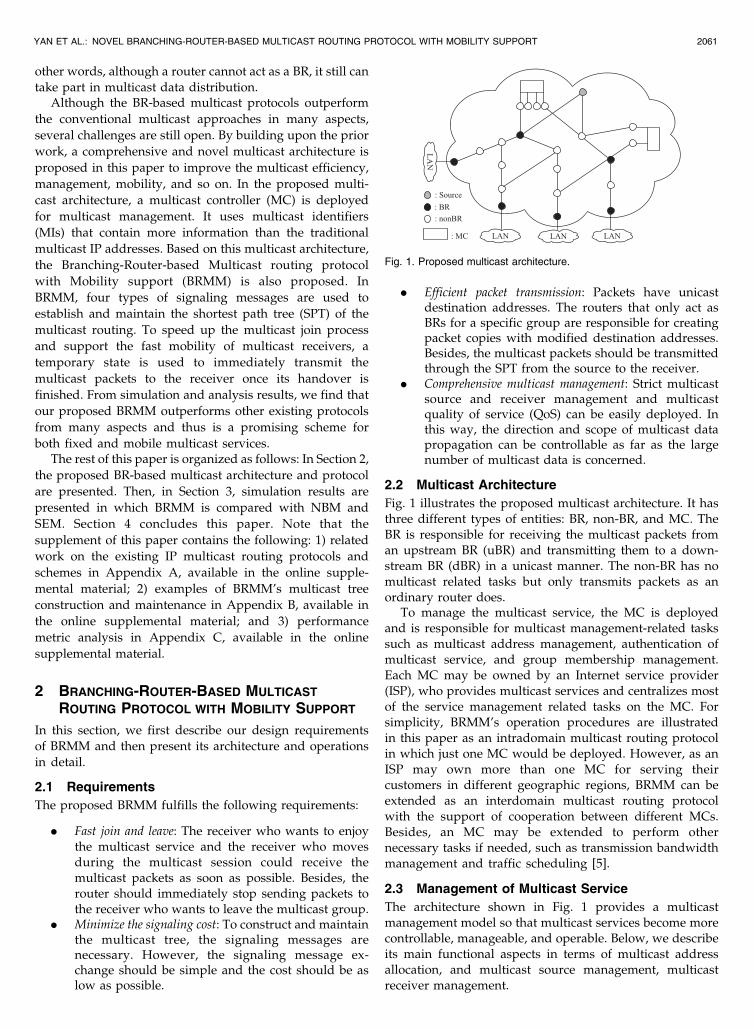
Fig. 1 illustrates the proposed multicast architecture. It hasthree different types of entities: BR, non-BR, and MC. TheBR is responsible for receiving the multicast packets froman upstream BR (uBR) and transmitting them to a down-stream BR (dBR) in a unicast manner. The non-BR has nomulticast related tasks but only transmits packets as anordinary router does.
To manage the multicast service, the MC is deployedand is responsible for multicast management-related taskssuch as multicast address management, authentication ofmulticast service, and group membership management.Each MC may be owned by an Internet service provider(ISP), who provides multicast services and centralizes mostof the service management related tasks on the MC. Forsimplicity, BRMM’s operation procedures are illustratedin this paper as an intradomain multicast routing protocolin which just one MC would be deployed. However, as anISP may own more than one MC for serving theircustomers in different geographic regions, BRMM can beextended as an interdomain multicast routing protocolwith the support of cooperation between different MCs.Besides, an MC may be extended to perform othernecessary tasks if needed, such as transmission bandwidthmanagement and traffic scheduling [5].
2.3 Management of Multicast Service
The architecture shown in Fig. 1 provides a multicastmanagement model so that multicast services become morecontrollable, manageable, and operable. Below, we describeits main functional aspects in terms of multicast addressallocation, and multicast source management, multicastreceiver management.
YAN ET AL.: NOVEL BRANCHING-ROUTER-BASED MULTICAST ROUTING PROTOCOL WITH MOBILITY SUPPORT 2061
Fig. 1. Proposed multicast architecture.

2.3.1 Multicast Address Allocation
A multicast source is a content server that sends multicastinformation in a relatively fixed period. Thus, a multicastsource should be dynamically allocated a multicast addressto send a specific type of multicast flow. The MC managesthe allocation and reclamation of multicast addressesdenoted by multicast identifiers. It allocates a specific MIwhen a multicast service is requested for creation andreclaims the MI when the service is requested fortermination to guarantee no conflicts between variousmulticast flows.
Fig. 2 shows the format of MI. It does not onlydifferentiate multicast services as it contains extendedinformation. In particular, an MI is 128-bit long and hasfive parts:
. To present the source, its media access control(MAC) address is contained in the MI as the 48-bit“MAC of source” field.
. The second part is the 16-bit “Group ID” field thatidentifies a special group provided by the samesource.
. The third part is the 8-bit “Type of service” field ofthis multicast group, such as video conferencing,online game, software distribution, and so on.
. The fourth part is the 8-bit “Priority” field of thismulticast service. In this way, the BR can differenti-ate the service and apply multicast QoS policy. Alarger value of “Priority” means a more urgentservice and should be allocated more resources forthe multicast service supporting.
. The last part is the 48-bit “Reserved” field for thefuture extensions.
2.3.2 Multicast Source Management
The edge router in the Internet should have theresponsibility to cooperate with the MC for the multicastservice management.
We assume that the access router (AR) at the source nodeis the first router to forward the multicast packets from thesource, and it may support the wired or wireless access. TheAR of the source can use a configuration file containingauthentication result, service duration time, service type,and so on to filter the packets to manage the multicastsource. In particular, before a multicast service is created,the multicast source must submit a request to its AR. Whenthe AR receives that request, it should redirect that requestmessage to the MC for the source authentication. After thesuccessful source authentication, the MC assigns an MI anda permitted duration time for this source. The MC thenconfigures these parameters as an entry of multicast sourceauthority list. In addition, the MC returns the authenticationresult to the AR that will establish the configuration file.When a multicast service is terminated by the source, thesource must submit a request again, asking the MC toreclaim the MI and the timer.
2.3.3 Multicast Receiver Management
The AR of the receiver is also responsible for performingauthentication and authorization to the receiver who wishesto enjoy a multicast service to control the multicast receiverand to collect accounting information. The authenticationand authorization of a multicast receiver must ensure thatonly the requested and authorized multicast receivers canreceive the multicast traffic over the network.
The AR must detect the join message originated by thereceiver to perform the multicast join. When detecting that areceiver sends a leave message or learning via the timer thata receiver leaves a multicast group, the AR stops forward-ing the traffic to the receiver and reports the leaving stateand accounting information to the MC.
2.4 BRMM Routing
In BRMM, four types of signaling messages are defined:Join, Tree, Select, and Leave. The basic message header ofBRMM is illustrated in Fig. 3. When it is used in thesignaling message, it should be examined hop by hopunless the router is not BRMM capable. The header also actsas an extended routing header contained in the multicastpackets. In this case, it is only examined by the destinationnode, which is either a BR or a receiver.
The 4-bit “BRMM Version” field denotes the protocolversion. The 3-bit “Type” field denotes the four types of thesignaling messages:
. 001 is for the Join message, which is sent from thereceiver to the source and used for the multicast treeestablishment and multicast state refreshment.
. 010 is for the Tree message, which is sent from thesource to the receiver and used as the response ofjoin message.
. 011 is for the Select message, which is used toreselect the BR.
. 100 is for the Leave message, which is sent from thereceiver to the source for the multicast termination.
The “B” field is a 1-bit flag identifying whether the nodesending the message is a BR: 1 denotes “yes” and 0 denotes“no.” The “MI” field denotes the associated multicastservice, and the last three fields are the addresses of therelated dBR, uBR and ancestor uBR, respectively.
To construct the multicast tree and forward the multicastpackets accordingly, every BR maintains a multicast statetable (MST) as shown in Fig. 4. The “S” field is the sourceaddress of this multicast service. The “MI” field is used toidentify the multicast service. To aggregate the multicaststate, the receiver’s AR (called AR for simplicity in thefollowing description) acts as a BR when at least onereceiver in its subnet joins the multicast group. In this way,
2062 IEEE TRANSACTIONS ON PARALLEL AND DISTRIBUTED SYSTEMS, VOL. 24, NO. 10, OCTOBER 2013
Fig. 2. Format of MI.
Fig. 3. Format of BRMM message header.

the AR is the BR at the lowest layer. The “Timer0” field isonly used by the AR to refresh the SPT. Before the timer inthe “Timer0” field expires, the AR should send a Joinmessage to the source presented in the “S” field to refreshthe SPT. The “uBR” and “dBR” fields are the addresses ofupstream BR and downstream BR of this BR, respectively.The addresses of uBR and dBR are learned during themulticast join process. Corresponding to uBR and everydBR in the MST, each timer in the “Timer1” and “Timer2”fields is used to update the corresponding states.
Besides, the “T” flag field is maintained in the entries ofdBR list. When a BR receives the Join message from an AR,the BR adds it to the dBR list and sets the “T” flag to 1 first,and then the BR starts to transmit packets to the ARtemporarily. When the timer at the “Timer2” field expiresand the BR receives no Tree/Join message, the state isdeleted and the BR stops transmitting packets to the dBR.
If the Tree message sent to the AR is received by the BRbefore the timer in the “Timer2” field expires, the BRrecognizes that the SPT to the AR traverses itself. Then, theBR sets the “T” flag to 0 and continues to send packets tothe AR. If another Join message is received before the timerof the “Timer2” field expires and the BR finds that the SPTto the AR is still not established, the BR maintains “T” flagto be 1 and continues to send packets to the AR because thatmeans the SPT establishment for the new joiner is failed. Ifthe BR cannot receive the Tree message after three times ofthe timer duration, the state of AR is deleted and the BRstops transmitting packets to the AR.
2.4.1 Multicast Join Process
When a receiver wants to subscribe to a multicast groupidentified by the MI field, it sends out a Join message to itsattached AR. When the AR receives the Join(0,MI,MN)message (for simplicity, we only consider three parts in asignaling message: B flag, MI, and Address of dBR), itrecognizes that a receiver as the mobile node (i.e., MN)1
want to join the group identified by the MI. Then, the ARreconstructs a Join message as Join(1,MI,AR) and sends it tothe source if the AR has no state of the multicast group. Theaddress of the source is learned during the receiverauthentication process, which is stored in the MC as the“MI ! Multicast source IP” mapping entry.
When the first BR in the reverse path receives the Joinmessage from the AR, it adds the AR into the dBR list andsets the corresponding “T” flag to 1. At the same time, theBR forwards the Join message to the source. When thesource receives this message finally, it realizes that the ARwants to join the group identified by MI. Then, the sourcechecks whether the outgoing interfaces of this AR and itscurrent dBR (C-dBR) are identical (initially, the first ARwho joins the multicast group is the first C-dBR of the
source). If not, the source recognizes that the AR should actas a new BR. Then, the source sends the Tree message tothe AR to construct the SPT from the source to the AR. Atthe same time, the C-dBR of the source is carried in theTree message.
All the BRMM capable intermediate routers should refreshtheir dBR and uBR lists when they act as BRs after theoperations illustrated in Fig. 5, which are described below.
The intermediate router R in Fig. 5 first checks whether itis the C-dBR when the Tree message arrives. If theintermediate router is the C-dBR and the AR is not storedin its dBR list, the intermediate router will check whetherthere is dBR in its dBR list has the same outgoing interfacewith the AR. If so, a new branch may exist in thedownstream and then the intermediate router replaces theC-dBR with the dBR in the Tree message. Otherwise, itmeans that the AR is a new branch, and the intermediaterouter thus inserts the AR into its dBR list directly. If the ARis already in its MST and the “T” flag set as 1, theintermediate router changes the “T” flag set to be 0.
If the intermediate router is not the C-dBR, it checkswhether the outgoing interfaces of the AR and the C-dBRare the same. If not, the intermediate router takes itself as anew BR of the C-dBR and the AR. In addition, theintermediate router first sends a Select message to uBR(the source address of the Tree message) to announce itsself-selection to be the new BR. When the uBR receives thisSelect message, it updates its C-dBR to be this intermediaterouter. Furthermore, the intermediate router continuessending the Tree message to the AR to construct the SPT.A Tree message is also sent to the old C-dBR to update theold C-dBR’s MST because the intermediate router acts asthe new uBR of the old C-dBR from now on.
When the AR and the old C-dBR receive the Treemessages finally, the C-dBR in the current Tree message isinserted to their uBR lists. When uBR receives the Selectmessage, it refreshes its dBR list and replaces its C-dBRwith the intermediate router.
An example is given in Appendix B, available in theonline supplemental material, to illustrate the procedurein detail.
2.4.2 Multicast Leave Process
When the MN wants to leave the multicast group identifiedby the MI, it sends a Leave message to the attached AR. TheAR then stops the packet transmission to the MN and sends
YAN ET AL.: NOVEL BRANCHING-ROUTER-BASED MULTICAST ROUTING PROTOCOL WITH MOBILITY SUPPORT 2063
Fig. 5. Process of Tree message.
Fig. 4. MST of BR.
1. To visually describe the procedure of BRMM when the receiver is amobile terminal, we here use the term, mobile node, to uniformly denotethe multicast receiver.

another Leave message to the MC. In the leave message, the“Timer” field contains the serving time of the MN. Whenthe AR finds that there is no attaching node in the multicastgroup, it sends a Leave message to its uBR.
When AR’s uBR receives the Leave message, the processshown in Fig. 6 is performed. For instance, it finds that theAR should not act as a BR anymore and thus deletes the ARfrom its dBR list. If there is only one dBR (denoted by BR1in Fig. 6) left in the dBR list after the deletion of the AR, itshould not act as a BR anymore and then it reconstructs aSelect message and sends to its uBR. In the Select message,the address of BR1 is contained. When the uBR receive theSelect message, it will update its dBR list accordingly tocontain the BR1 as its dBR.
2.4.3 Packet Delivery
When the source starts sending packets, the state of thecorresponding MI is examined. A packet is directlyforwarded to the dBRs of the source in unicast manner.When the subsequent dBRs receive the packet, the sameoperation is repeated. Thus, if a router receiving the packetis not the dBR nor BRMM capable, the BRMM header is notexamined. The router thus forwards the packet to thespecified destination in a unicast manner.
2.4.4 Tree Maintenance
When the Tree message travels from a source to a receiver,the multicast state is constructed in the related BRs. Afterthis process, the multicast tree should be refreshed periodi-cally to keep it alive and timely detect the failure cases.
After the shortest path is established from a source to areceiver in BRMM, the receiver sends out the Join messageto the AR to update its state actively, or the AR queries thestate of the receiver passively as specified in Internet groupmanagement protocol (IGMP) or multicast listener dis-covery (MLD). The signaling message sent to the dBR is aTree message to refresh the state of the “Timer1” field.When the state is not refreshed for three times of the timerduration in the “Timer1” field, the dBR considers that thepath fails and the dBR sends out a Join message directly toits ancestor (i.e., parent of its uBR), and then the processjust becomes as the new join of dBR. The timer in the“Timer0” field of the AR is used to refresh the SPT fromthe source to the AR. In this way, the AR actively sends aJoin message to the source to adapt the topology changeand the shortest path change. The responded Tree messagerefreshes the states of the bypassed BRs and the shortestpath can be updated. So, the timer value in the “Timer0”field is longer than that in the “Timer1” field to decreasethe signaling cost.
This scheme maintains the BRMM tree recursively. Thelink failure can be detected and multicast tree can bereconstructed as soon as possible. At the same time, the SPTcan always be refreshed. An example is presented inAppendix B, available in the online supplemental material.
2.4.5 Mobility Support
The basic operation of the mobility support in BRMM isillustrated in Fig. 7. When the MN moves from AR1 to AR2,BRMM employs a link layer (L2) movement detection topredict the MN’s next location. As shown in Fig. 7(1), oncethe MN enters an overlapped area of the boundary cells oftwo subnets, it receives an L2 beacon from a new accesspoint (AP) as shown in Step 1. Immediately, the MN notifiesthe current AR (i.e., AR1) about the possible handover bysending a handover initiate signaling message, whichcontains the MAC address of the new AP as shown inStep 2. Note that in this case, the MN is not yet connected tothe radio link of the new AR (i.e., AR2) and is still connectedto the old AP. Hence, when AR1 receives the handoverinitiate signaling message, it sends a Join message to its uBRinstead of AR2 to join the multicast group identified by theMI and the address of AR2 is contained in the Join messageas shown in Step 3.
When the uBR receives this message, it recognizes thatAR2 wants to join the multicast group identified by the MI.Then, AR2 is added into the dBR list of the uBR and the“T” flag is set to 1, because AR2 is not contained in itscurrent dBR list. Besides, as shown in Step 4, the uBR sendsa Join message to the source to establish AR2’s SPT inadvance. At the same time, the uBR sends the multicastpackets and a Tree message to AR2 as shown in Step 5.Because the MN is not attached to AR2 at this moment, themulticast packets are buffered at AR2. Note that the size ofthe buffer is dependent on the special configuration andQoS policy. Specifically, the L2 handover is first launchedby the MN as shown in Fig. 7(2). The MN then attaches tothe new AP and sends the Join message to AR2 as shownin Step 6. After that, AR2 checks the state of the multicastgroup identified by the MI. Since AR2 has the multicaststate corresponding to the MI, the following packets can beforwarded to the MN.
As shown in Step 7, AR2 waits for the Tree message sentfrom the source. At the same time, it refreshes thetemporary state in the uBR to receive the packets from theuBR continually. After receiving the Tree message sent fromthe source as shown in Step 8, AR2 stops the refreshment ofmulticast state and the following packets are transmitted
2064 IEEE TRANSACTIONS ON PARALLEL AND DISTRIBUTED SYSTEMS, VOL. 24, NO. 10, OCTOBER 2013
Fig. 6. Process of Leave message.
Fig. 7. Mobility support in BRMM.
through the SPT. The BR will delete the temporary state ofAR2 after the timeout or after receiving the Leave messagesent from AR2.
BRMM may provide a significant reduction in thehandover latency of mobile multicast because the currentBR is used as a temporary uBR and also achieve a similareffect as the approach presented in [6], which dynamicallyrecognizes mobility. In other words, the optimized mobilityperformance of BRMM depends on the density of theserving BRs. When there are many serving BRs, the averagedistance between the uBR and new AR is short and the MNcan be served more quickly. However, the handoverprocess of the MN is just the new join process when theprevious AR (i.e., AR1) and new AR (i.e., AR2) have nocommon BR except the source node in the extreme case.
3 SIMULATION AND ANALYSIS
In this section, we evaluate the performance of BRMM andcompare it with existing schemes. We mainly study theperformance improvement of BRMM compared with NBM[3] and SEM [4], because all the three schemes arecompletely BR-based schemes. The introduction of NBMand SEM with other multicast schemes is provided inAppendix A, available in the online supplemental material.The related performance metric analysis and calculationare given in Appendix C, available in the online supple-mental material. The simulation study was conducted inNS v2.31 [7], and we separately implemented the SEM,NBM, and BRMM under the Agent of NS v2.31.
3.1 Simulation Scenarios
The topology is randomly generated using nem [8], and theaverage node degree of generated topology is fixed at 3.5.To study the protocols in different cases, we set up twodifferent simulation scenarios with 200 and 2,000 nodesseparately as shown in Table 1. Without loss of generality,we assume that only one receiver is connected to each AR inthe topology. The presence of one or many receivers
attached to an AR through IGMP or MLD does notinfluence the cost of the tree, so we do not consider theaggregation provided by the multicast service at the localnetwork level. We chose a single and fixed node to act asthe multicast source and each member would join themulticast session at different random time. The identities ofthe group members (i.e., the source and receivers) wereselected randomly in each simulation run. We run eachsimulation scenario for 50 times and present the averageresults for different protocols.
3.2 Cost of Tree Maintenance
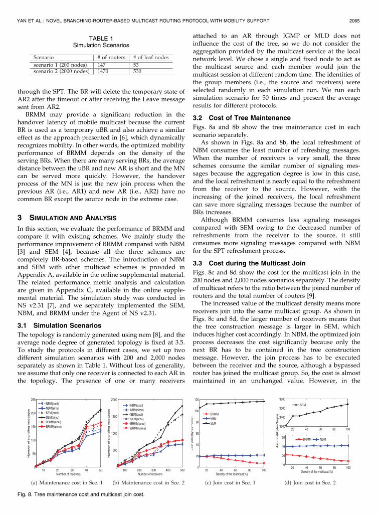
Figs. 8a and 8b show the tree maintenance cost in eachscenario separately.
As shown in Figs. 8a and 8b, the local refreshment ofNBM consumes the least number of refreshing messages.When the number of receivers is very small, the threeschemes consume the similar number of signaling mes-sages because the aggregation degree is low in this case,and the local refreshment is nearly equal to the refreshmentfrom the receiver to the source. However, with theincreasing of the joined receivers, the local refreshmentcan save more signaling messages because the number ofBRs increases.
Although BRMM consumes less signaling messagescompared with SEM owing to the decreased number ofrefreshments from the receiver to the source, it stillconsumes more signaling messages compared with NBMfor the SPT refreshment process.
3.3 Cost during the Multicast Join
Figs. 8c and 8d show the cost for the multicast join in the200 nodes and 2,000 nodes scenarios separately. The densityof multicast refers to the ratio between the joined number ofrouters and the total number of routers [9].
The increased value of the multicast density means morereceivers join into the same multicast group. As shown inFigs. 8c and 8d, the larger number of receivers means thatthe tree construction message is larger in SEM, whichinduces higher cost accordingly. In NBM, the optimized joinprocess decreases the cost significantly because only thenext BR has to be contained in the tree constructionmessage. However, the join process has to be executedbetween the receiver and the source, although a bypassedrouter has joined the multicast group. So, the cost is almostmaintained in an unchanged value. However, in the
YAN ET AL.: NOVEL BRANCHING-ROUTER-BASED MULTICAST ROUTING PROTOCOL WITH MOBILITY SUPPORT 2065
TABLE 1Simulation Scenarios
Fig. 8. Tree maintenance cost and multicast join cost.

2,000 nodes scenario, more routers are deployed in thenetwork. Then, the average hops between the leaf routerand the source node increases, which induces higher cost.Then, the proposed BRMM utilizes the existing multicastrouters to speed up the join process and cut down the costduring the join process. We can find from Figs. 8c and 8d,with the increase of the multicast density, the cost of BRMMdecreases owing to the shortened path between the receiverand its nearest upper layer BR.
3.4 Latency
The following two kinds of latency, namely join latency andhandover latency, are considered:
. For the receiver who joins the multicast group for thefirst time, the latency is defined to be the time fromthe moment that the receiver sends out the joinmessage to the moment that the receiver receives thefirst multicast packet.
. For the receiver who changes its point of attachmentfrom one AR to another AR, the latency is defined tobe the time from the moment that it cannot receiveany multicast packet from the old AR to the momentthat it receives the first packet from the new AR [10].
3.4.1 Join Latency for the First Time
For NBM and SEM, the receiver must send a Join messageuninterrupted to the source to join the multicast group. Toestablish the SPT from the source to the receiver, anothersignaling message should be sent from the source to thereceiver so that the join process is completed. Accordingly,the join latency of NBM and SEM equals to the round triptime (RTT) between the source and the receiver. However,the join latency of BRMM equals to the RTT between thereceiver and the nearest existing BR.
As shown in Figs. 9a and 9b, the join latency of BRMM islower than that of NBM owing to the temporary joinprocess. Besides, with the increasing of joined receivers, theaverage join latency of BRMM decreases owing to theshortened path between the receiver and the temporaryuBR. However, the receivers always exchange the signalingmessage with the source to join the multicast group in NBMand SEM, and then the join latency is nearly unchangedwith the number of joined receivers. Besides, due to theincreased number of receivers, the join latency of SEMincreases. The reason is that even when a single node joins
the multicast group, all the receivers have to be included inthe signaling message sent by the source to refresh themulticast tree and the BRs, which causes the increase ofprocessing latency.
Compared with the result shown in Fig. 9a, the joinlatency shown in Fig. 9b is higher due to the large topologywith 2,000 nodes and the enlarged distance between thereceivers and the source. The increasing rates of join latencywith the increased number of receivers in SEM and NBMare more obvious in this result. That is because morereceivers have to join the multicast group and heaviersignaling messages should be processed. The average joinlatency of BRMM, NBM, and SEM is listed in Table 2.As shown, BRMM could reduce the join latency more than20 percent compared with NBM and SEM.
3.4.2 Handover Latency for the Mobile Receiver
To evaluate the handover latency of an MN (i.e., mobilereceiver), we assume that the last hop between the receiverand the AR is a wireless link, and every AR thusimplements with AP functionalities. The latency andbandwidth of the WLAN link are set to 1 ms and 2 Mbpsseparately. In our simulation, the MN moves between twoneighbor APs with the coverage of 100 m. To manifest themobility performance of BRMM, we set different multicastdensities in our simulation that denotes percentages ofreceivers joined the same multicast group.
Figs. 9c and 9d plot the results of handover latency intwo scenarios, separately. As shown, BRMM can reduce thehandover latency significantly with the increasing of themulticast density. That is because when the density ofmulticast is small, the distance between the uBR of previousAR and the new AR is far. However, with the increasing ofthe multicast density, more BRs exist in the network and thenew AR can join the multicast group through the temporaryuBR more quickly.
For SEM and NBM, there is no mobility support so thatthe handover requires a new join process for the MN.
2066 IEEE TRANSACTIONS ON PARALLEL AND DISTRIBUTED SYSTEMS, VOL. 24, NO. 10, OCTOBER 2013
Fig. 9. First join latency and handover latency.
TABLE 2Average Join Latency
Besides, more receivers exist in the larger scenario, so thehandover latency of SEM induces longer handover latencycompared with NBM as shown in Fig. 9d.
The handover latency seems to have no relationshipwith the density of multicast. However, the latency in thescenario 2 (2,000 nodes) is larger than that in the scenario 1(200 nodes) due to the prolonged path between the receiverand the source.
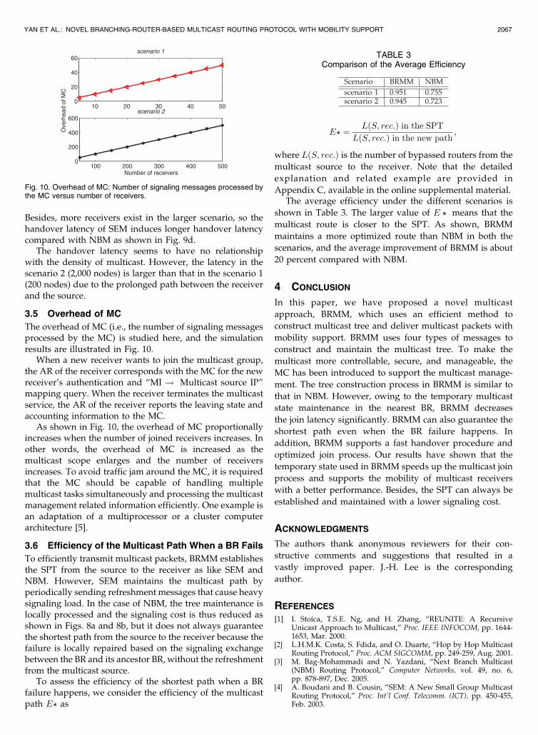
3.5 Overhead of MC
The overhead of MC (i.e., the number of signaling messagesprocessed by the MC) is studied here, and the simulationresults are illustrated in Fig. 10.
When a new receiver wants to join the multicast group,the AR of the receiver corresponds with the MC for the newreceiver’s authentication and “MI ! Multicast source IP”mapping query. When the receiver terminates the multicastservice, the AR of the receiver reports the leaving state andaccounting information to the MC.
As shown in Fig. 10, the overhead of MC proportionallyincreases when the number of joined receivers increases. Inother words, the overhead of MC is increased as themulticast scope enlarges and the number of receiversincreases. To avoid traffic jam around the MC, it is requiredthat the MC should be capable of handling multiplemulticast tasks simultaneously and processing the multicastmanagement related information efficiently. One example isan adaptation of a multiprocessor or a cluster computerarchitecture [5].
3.6 Efficiency of the Multicast Path When a BR Fails
To efficiently transmit multicast packets, BRMM establishesthe SPT from the source to the receiver as like SEM andNBM. However, SEM maintains the multicast path byperiodically sending refreshment messages that cause heavysignaling load. In the case of NBM, the tree maintenance islocally processed and the signaling cost is thus reduced asshown in Figs. 8a and 8b, but it does not always guaranteethe shortest path from the source to the receiver because thefailure is locally repaired based on the signaling exchangebetween the BR and its ancestor BR, without the refreshmentfrom the multicast source.
To assess the efficiency of the shortest path when a BRfailure happens, we consider the efficiency of the multicastpath E? as
E? ¼ LðS; rec:Þ in the SPT
LðS; rec:Þ in the new path;
where LðS; rec:Þ is the number of bypassed routers from the
multicast source to the receiver. Note that the detailed
explanation and related example are provided in
Appendix C, available in the online supplemental material.The average efficiency under the different scenarios is
shown in Table 3. The larger value of E ? means that the
multicast route is closer to the SPT. As shown, BRMM
maintains a more optimized route than NBM in both the
scenarios, and the average improvement of BRMM is about
20 percent compared with NBM.
4 CONCLUSION
In this paper, we have proposed a novel multicast
approach, BRMM, which uses an efficient method to
construct multicast tree and deliver multicast packets with
mobility support. BRMM uses four types of messages to
construct and maintain the multicast tree. To make the
multicast more controllable, secure, and manageable, the
MC has been introduced to support the multicast manage-
ment. The tree construction process in BRMM is similar to
that in NBM. However, owing to the temporary multicast
state maintenance in the nearest BR, BRMM decreases
the join latency significantly. BRMM can also guarantee the
shortest path even when the BR failure happens. In
addition, BRMM supports a fast handover procedure and
optimized join process. Our results have shown that the
temporary state used in BRMM speeds up the multicast join
process and supports the mobility of multicast receivers
with a better performance. Besides, the SPT can always be
established and maintained with a lower signaling cost.
ACKNOWLEDGMENTS
The authors thank anonymous reviewers for their con-
structive comments and suggestions that resulted in a
vastly improved paper. J.-H. Lee is the corresponding
author.
REFERENCES
[1] I. Stoica, T.S.E. Ng, and H. Zhang, “REUNITE: A RecursiveUnicast Approach to Multicast,” Proc. IEEE INFOCOM, pp. 1644-1653, Mar. 2000.
[2] L.H.M.K. Costa, S. Fdida, and O. Duarte, “Hop by Hop MulticastRouting Protocol,” Proc. ACM SIGCOMM, pp. 249-259, Aug. 2001.
[3] M. Bag-Mohammadi and N. Yazdani, “Next Branch Multicast(NBM) Routing Protocol,” Computer Networks, vol. 49, no. 6,pp. 878-897, Dec. 2005.
[4] A. Boudani and B. Cousin, “SEM: A New Small Group MulticastRouting Protocol,” Proc. Int’l Conf. Telecomm. (ICT), pp. 450-455,Feb. 2003.
YAN ET AL.: NOVEL BRANCHING-ROUTER-BASED MULTICAST ROUTING PROTOCOL WITH MOBILITY SUPPORT 2067
Fig. 10. Overhead of MC: Number of signaling messages processed bythe MC versus number of receivers.
TABLE 3Comparison of the Average Efficiency
[5] Y. Yang, J. Wang, and M. Yang, “A Service-Centric MulticastArchitecture and Routing Protocol,” IEEE Trans. Parallel andDistributed Systems, vol. 19, no. 1, pp. 35-51, Jan. 2008.
[6] J. Xie and I.F. Akyildiz, “A Novel Distributed Dynamic LocationManagement Scheme for Minimizing Signaling Costs in MobileIP,” IEEE Trans. Mobile Computing, vol. 1, no. 3, pp. 163-175, July-Sept. 2002.
[7] K. Fall and K. Varadhan, “The Ns Manual,” http://www.isi.edu/nsnam/ns/ns-documentation.html, 2013.
[8] D. Magoni and J.-J. Pansiot, “Internet Topology Modeler Based onMap Sampling,” Proc. IEEE Int’l Symp. Computers Comm. (ISCC),pp. 1021-1027, July 2002.
[9] J.F. Guan, H.C. Zhou, Y.J. Qin, and H.K. Zhang, “Multi-HopMulticast Listener Discovery Protocol,” Proc. IET Int’l Conf.Wireless, Mobile and Multimedia Networks (ICWMMN), pp. 422-425, Oct. 2008.
[10] J. Xie and U. Narayanan, “Performance Analysis of MobilitySupport in IPv4/IPv6 Mixed Wireless Networks,” IEEE Trans.Vehicular Technology, vol. 59, no. 2, pp. 962-973, Feb. 2010.
Zhiwei Yan received the PhD degree from theNational Engineering Laboratory for Next Gen-eration Internet Interconnection Devices, BeijingJiaotong University. He started working at ChinaInternet Network Information Center in 2011. Hisresearch interests include mobility management,network security, and next-generation Internet.
Jong-Hyouk Lee received the BS degree ininformation system engineering from DaejeonUniversity in 2004. He received the MS andPhD degrees in computer engineering fromSungkyunkwan University, Korea, in 2007 and2010, respectively. In 2009, he joined theproject team IMARA at INRIA, where heundertook the protocol design and implementa-tion for IPv6 vehicular (ITS) communication andsecurity. He started his academic profession in
the Network, Security, and Multimedia Department, Telecom Bretagne,France, in 2012 as an assistant professor. He is now an assistantprofessor in the Department of Computer Software Engineering,Sangmyung University, Republic of Korea. He is an associate editorof Wiley Security and Communication Networks and editorial boardmember of IEEE Transactions on Consumer Electronics. His researchinterests include authentication, privacy, and mobility management. Heis a senior member of the IEEE.
Sean Shen received the PhD degree from theMathematics and Electronics and ComputerEngineering Department, Purdue University in2007. He was with Huawei as a senior research-er between 2007 and 2009 and focused onInternet research and standardization, especiallyin applications and Internet security. Since hejoined China Internet Network Information Cen-ter in 2009, he has been serving as the directorof the China Internet Network Information Center
Lab and director of the Advanced Research Department. He has beendirecting research and standardization work, including DNS, IP, and IoTareas. He has published various international and domestic standards,including RFC and WG drafts in the IETF, telecommunication industrialand national standards in China. He has been serving in variouscommittee and organizations in both international and domestic areas,such as member of national Internet standard planning committee, co-chair of Architecture of Ubiquitous network Working Group.
Chunming Qiao pioneered optical burst switch-ing or OBS, as well as integrated cellular and adhoc relaying (e.g., Wi-Fi) technologies (iCAR)around 1999. He has been funded by about adozen of grants from the US National ScienceFoundation, and a dozen of major IT andtelecommunications companies including AlcatelResearch, Bellcore (Telcordia), Cisco, FujitsuLabs, Google, NEC Labs, Sprint AdvancedTechnology Labs, and so on. His research has
resulted in several patents, and has been featured in BusinessWeeks,Wireless Europe, and New Scientists. He has chaired dozens ofinternational conferences and served as editors for several major IEEEjournals/magazines. He has also chaired the IEEE Technical Sub-committee on Integrated Fiber and Wireless Technologies (FiWi). Hehas published hundreds of highly cited papers with an h-index of morethan 50. He gave contributions to optical and wireless networkarchitectures and protocols. He is a fellow of the IEEE.
. For more information on this or any other computing topic,please visit our Digital Library at www.computer.org/publications/dlib.
2068 IEEE TRANSACTIONS ON PARALLEL AND DISTRIBUTED SYSTEMS, VOL. 24, NO. 10, OCTOBER 2013