nova · the nova ™ comet ii midi lathe is intended for indoor use only. failure to do so may void...
TRANSCRIPT

118-0517-011 1
NOVA COMET II STAND
THIS MANUAL CONTAINS IMPORTANT INFORMATION REGARDING SAFETY, OPERATION, MAINTENANCE AND STORAGE OF THIS PRODUCT. BEFORE USE, READ CAREFULLY AND UNDERSTAND ALL CAUTIONS, WARNINGS, INSTRUCTIONS AND PRODUCT LABELS. FAILURE TO DO SO COULD RESULT IN SERIOUS PERSONAL INJURY AND/OR PROPERTY DAMAGE. THIS ACCESSORY CAN ONLY BE USED ON THE NOVA™ COMET II MIDI LATHE.
Publication 118-0517-011 Date: 09.May.2017
SKU: 47050
Ins
truc
tion
Ma
nu
al

118-0517-011 2
NOVA Comet Stand™ Features: Sturdy tubular steel design
Powder coat finish
Provides a mobile and stable work support for Comet II midi-lathe
Specially designed V-style legs allow more room under the lathe for maneuvering
Adjustable height to accommodate all turners
Mounts directly to your Comet II midi-lathe
NOTE: Due to NOVA’s continual product development and improvement policy, product features and
specifications may change without notice.
© Copyright 2000 -2017 by Teknatool International. All Rights Reserved. NOVA Comet II™ is a trademark of Teknatool International Ltd.
The information and specifications contained herein are subject to change. Teknatool International Ltd is not responsible for errors or omissions herein or for incidental damages in connection with the furnishing or use of this information.
Contact Teknatool: New Zealand Teknatool International Ltd
Phone: (+64) 9 477 5600 Fax: (+64) 9 477 5601 Email: [email protected] Website: www.teknatool.com
To contact your local dealer please visit our website: www.teknatool.com
United States Teknatool Service Center
Phone: 727-954-3433 Free Phone: 1-866-748-3025 Free Fax: 1-866-748-4193 Email: [email protected] Website: www.teknatool.com

118-0517-011 3
Table of Contents: GENERAL SAFETY RULES ................................................................. 4 Tools Required for Assembly: 2 Adjustable Wrenches ......................... 6
SPECIFICATIONS ............................................................................ 7 Unpacking and Clean-up ...................................................................... 7
INSTALLATION INSTRUCTIONS: ....................................................... 7 ASSEMBLY ....................................................................................... 7
Assembling Base to Column ............................................................. 7 ADJUSTMENTS ................................................................................ 8 COMET II STAND BREAKDOWN (A) ............................................. 10
COMET II STAND BREAKDOWN (B) ............................................. 11 PARTS LIST.................................................................................... 12
MAINTENANCE.................................................................................. 12 Remove all saw dust and chips from the lathe stand after each use.WARRANTY: ............................................................................... 12

118-0517-011 4
GENERAL SAFETY RULES Intended Use
This product is intended for consumer use only. This tool is not designed for professional use.
! WARNING! Failure to follow these rules may result in serious personal injury. People with electronic devices, such as pacemakers, should consult their physician(s) before using this product. Operation of electrical equipment in close proximity to a heart pacemaker could cause interference or failure of the pacemaker.
! WARNING: Some dust created by power sanding, sawing, grinding, drilling and other construction activities contains chemicals known to the State of California to cause cancer, birth defects or other reproductive harm. Some examples of these chemicals are: • Lead from lead-based paints. • Crystalline silica from bricks and cement and other masonry products, and arsenic and chromium from chemically-treated lumber. Your risk from these exposures varies, depending on how often you do this type of work. To reduce your exposure to these chemicals: work in a well ventilated area, and work with approved safety equipment, such as dust masks that are specially designed to filter out microscopic particles.
1. FOR YOUR OWN SAFETY, READ THE MANUAL BEFORE OPERATING THE TOOL. Learn the machine’s application, limitations and the specific
hazards particular to it.
2. ALWAYS USE A FULL FACE SHIELD. Strongly recommended. (Must
comply with ANSI STANDARD Z87.1 -USA) Everyday eye-glasses usually are only impact resistant and safety glasses only protect eyes. A full face shield will protect the eyes and face. Also use face or dust mask if cutting operation is dusty.
3. WEAR PROPER APPAREL. Do not wear loose clothing, gloves, neckties,
rings, bracelets or other jewelry which may get caught in moving parts. Non-slip footwear is recommended. Wear protective hair covering to contain long hair.
4. USE EAR PROTECTORS. Use ear plugs or muffs for any period of
operation. Use muffs rated to 103 DBA LEQ (8 hour).
5. DON’T USE IN DANGEROUS ENVIRONMENT. Don’t use power tools in
damp or wet locations, or expose them to rain. Keep work area well lighted. The NOVA™ Comet II Midi Lathe is intended for indoor use only. Failure to do so may void the warranty.
6. KEEP WORK AREA CLEAN. Cluttered areas and benches invite accidents.
Build-up of sawdust is a fire hazard.
7. KEEP CHILDREN AND VISITORS AWAY. The NOVA™ Comet II Midi Lathe accessories are not recommended for children or the infirm. Such
personnel and onlookers should be kept at a safe distance from the work area.

118-0517-011 5
8. MAKE WORKSHOP CHILDPROOF. Utilize locks, master switches, or by
removing starter/lockout keys.
9. GROUND ALL TOOLS. If the tool is equipped with a three-prong plug, it
should be plugged into a three hole electrical receptacle. If an adapter is used to accommodate a two prong receptacle, the adapter plug must be attached to a known ground. NEVER remove the third or grounding prong.
10. DISCONNECT TOOLS. Ensure the plug is removed from the wall socket
before servicing and when changing accessories such as blades, bits, cutters and fuses, etc.
11. AVOID ACCIDENTAL STARTING. Make sure switch is in the Off position
before plugging in power cord into the wall socket.
12. NEVER LEAVE MACHINE RUNNING UNATTENDED. Do not leave
machine unless it is turned off and has come to a complete stop.
13. KEEP GUARDS IN PLACE. Ensure guards are in working order.
14. USE CORRECT TOOLS. Do not use a tool or attachment to do a job for
which it was not designed.
15. DON’T FORCE THE TOOL. It will do the job better and be safer at the
rate/force for which it was designed.
16. MAINTAIN TOOLS IN TOP CONDITION. Keep tools sharp and clean for the
best and safest performance. Follow instructions for lubricating and changing accessories.
17. NEVER STAND ON THE TOOL. Serious injury could occur if the tool is tipped
or if the cutting tool is accidentally contacted.
18. REMOVE ADJUSTING KEYS AND WRENCHES. Form a habit of checking to
see that keys and adjusting wrenches are removed from tool before turning it on.
19. DON’T OVERREACH. Keep proper footing and balance at all times.
20. DIRECTION OF FEED. Feed work into the blade or cutter against the direction
of rotation.
21. ATTENTION TO WORK. Concentrate on your work. If you become tired or
frustrated, leave it for awhile and rest.
22. SECURE WORK. Use clamps or a vice to hold work when practical. It’s safer
than using your hand and frees both hands to operate tool.
23. CHECK DAMAGED PARTS. Before further use of the tool, any part that is
damaged should be carefully checked to ensure that it will operate properly and perform its intended function. Check for alignment of moving parts, binding of moving parts, mounting, and any other conditions that may affect its operation. Any damaged part should be properly repaired or replaced.
24. DRUGS, ALCOHOL OR MEDICATION. Do not operate machine while under
the influence of drugs, alcohol, or any medication.
25. DUST WARNING. The dust generated by certain woods and wood products
can be harmful to your health. Always use an approved dust mask and operate machinery in well-ventilated areas. In addition, provide a means for proper dust removal. Use wood dust collection systems whenever possible.
118-0517-011 6
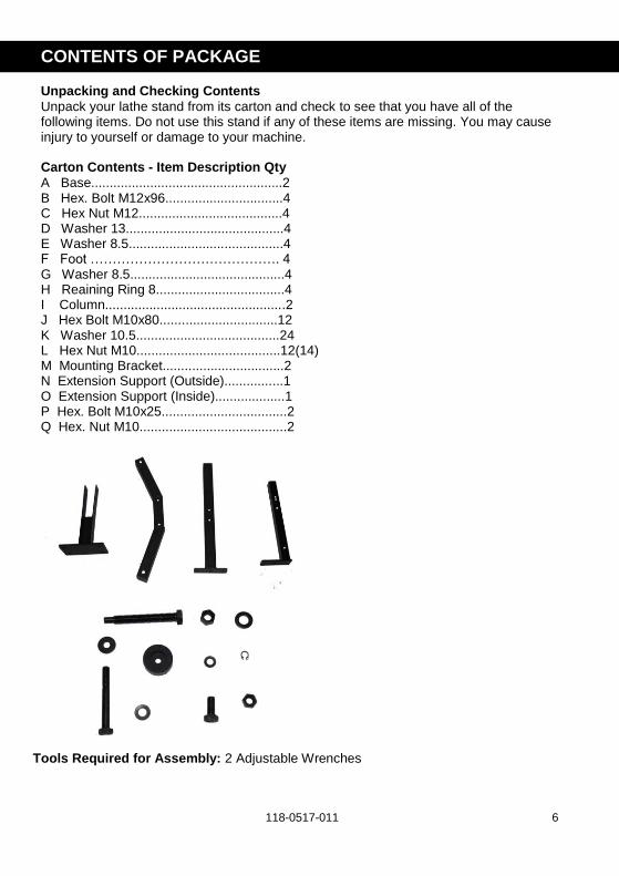
CONTENTS OF PACKAGE Unpacking and Checking Contents
Unpack your lathe stand from its carton and check to see that you have all of the following items. Do not use this stand if any of these items are missing. You may cause injury to yourself or damage to your machine. Carton Contents - Item Description Qty
A Base....................................................2 B Hex. Bolt M12x96................................4 C Hex Nut M12.......................................4 D Washer 13...........................................4 E Washer 8.5..........................................4 F Foot ……………………………………. 4 G Washer 8.5..........................................4 H Reaining Ring 8...................................4 I Column.................................................2 J Hex Bolt M10x80................................12 K Washer 10.5.......................................24 L Hex Nut M10.......................................12(14) M Mounting Bracket.................................2 N Extension Support (Outside)................1 O Extension Support (Inside)...................1 P Hex. Bolt M10x25..................................2 Q Hex. Nut M10........................................2
Tools Required for Assembly: 2 Adjustable Wrenches

118-0517-011 7
SPECIFICATIONS Width 6” to 7-11/16” Plate Dimension (L x W): Length 19-11/16” to 31-7/8” Version A----6-1/2” x 8-1/2” Working Height 24-1/2” to 34-1/2” Version B----4-1/3” x 8-1/2” Base Length 27-3/8” to 39-3/8” Base Width 24-1/4” Product Weight 37.5lbs Weight Capacity 220 lbs
Unpacking and Clean-up 1. Carefully finish removing all contents from shipping cartons. Compare contents of the shipping
cartons with the list of contents above. Place parts on a protected surface. 2. Report any shipping damage to your local distributor. 3. Set packing material and shipping cartons to the side. Do not discard carton until the stand has
been set up.
INSTALLATION INSTRUCTIONS:
! INSPECTION: Carefully inspect each individual part of the COMET STAND™ Accessory to ensure there are no cracked, broken, or bent components needed for a safe installation.
ASSEMBLY
Assembling Base to Column
1. Locate one Base (part #1) and one Column (part #9).
2. Install two bolts (part #10) and two washers (part #11) through the Column flange and into the base.
3. Add two washers (part #11) and two hex nuts (parts #12) to the bolts underneath the base. (Fig. 01)
4. Repeat steps to complete the second Base and Column assembly.
Installing Extension Supports to Base and Column Assembly 1. Make sure that feet of both base and column assemblies are pointing outward. 2. Assemble the Inside Extension Support bracket (part #15) to the inside of the left Base and Column assembly. Install two bolts (part #10) and two washers (part #11) through the Column and into the Inside Extension Support bracket flange. Add two washers (part #11) and two hex nuts (part #12) to the bolts through the flange of the Inside Extension Support bracket. (Fig. 02)
Fig. 01
Fig. 02

118-0517-011 8
3.) Assemble the Outside Extension Support bracket (part #14) to the inside of the right Base and Column assembly. Install two bolts (part #10) and two washers (part #11) through the Column and into the Outside Extension Support bracket flange. Add two washers (part #11) and two hex nuts (part #12) to the bolts through the flange of the Outside Extension Support bracket. (Fig. 03)
Connecting and Adjusting the Extension Supports 1. Slip the Inside Extension Support bracket (part #15) into the Outside Extension Support bracket (part #14). 2. Add two bolts (part #16) and two hex nuts (part #17) to the welded hex nuts located on the Outside Extension Support bracket (part #14). (Fig. 04) 3. Only hand-tighten at this point, secure after
ADJUSTMENTS
Determining Proper Lathe Height 1. Install the Mounting Brackets (part #13) to the top of both Columns (part #9) using two bolts (part #10) and two washers (part #11). (Fig. 05) Add two washers (part #11) and two hex nuts (part #12) to the bolts. Hand-tighten at this point until proper lathe height has been determined. 2. Next, measure the distance from the base of the lathe to the point on the live center. (Fig. 06) 3. Measure the distance from your elbow to the floor. 4. Subtract the lathe height measurement from the elbow height measurement. This number represents the approximate height of the lathe stand. Example: 45” (elbow to floor) -12.5” (base to live center) = 32.5” (stand height).
Fig. 04
Fig. 05
Fig. 06
Fig. 03

118-0517-011 9
Adjusting for Lathe Length The Comet Stand can be adjusted from 19-11/16” to 31-7/8” in length. 1. Measure the length of your lathe from center of one bolt hole to the center of the other. 2. Loosen the two locking bolts (part #16) on the Outside Extension Support (part# 14) and slide the Column Supports inward or outward to the desired length. 3. Tighten the two locking bolts (part #16) and then tighten the two locking nuts (part #17). (Fig. 07)
Leveling the Lathe Stand 1. Loosen the locking nut (part # 3) on the Base assembly. 2. Adjust the leveling bolt (part # 2) to the Desired height. 3. Tighten down the locking nut (part # 3) to retain the adjustment. (Fig. 08)
Fig. 07
Fig. 08

118-0517-011 10
COMET II STAND BREAKDOWN (A)
Version A:

118-0517-011 11
COMET II STAND BREAKDOWN (B)
Version B:
118-0517-011 12
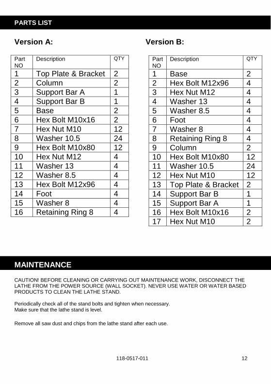
PARTS LIST
Version A: Version B: Part NO
Description QTY
1 Top Plate & Bracket 2
2 Column 2
3 Support Bar A 1
4 Support Bar B 1
5 Base 2
6 Hex Bolt M10x16 2
7 Hex Nut M10 12
8 Washer 10.5 24
9 Hex Bolt M10x80 12
10 Hex Nut M12 4
11 Washer 13 4
12 Washer 8.5 4
13 Hex Bolt M12x96 4
14 Foot 4
15 Washer 8 4
16 Retaining Ring 8 4
MAINTENANCE CAUTION! BEFORE CLEANING OR CARRYING OUT MAINTENANCE WORK, DISCONNECT THE LATHE FROM THE POWER SOURCE (WALL SOCKET). NEVER USE WATER OR WATER BASED PRODUCTS TO CLEAN THE LATHE STAND. Periodically check all of the stand bolts and tighten when necessary. Make sure that the lathe stand is level.
Remove all saw dust and chips from the lathe stand after each use.
Part NO
Description QTY
1 Base 2
2 Hex Bolt M12x96 4
3 Hex Nut M12 4
4 Washer 13 4
5 Washer 8.5 4
6 Foot 4
7 Washer 8 4
8 Retaining Ring 8 4
9 Column 2
10 Hex Bolt M10x80 12
11 Washer 10.5 24
12 Hex Nut M10 12
13 Top Plate & Bracket 2
14 Support Bar B 1
15 Support Bar A 1
16 Hex Bolt M10x16 2
17 Hex Nut M10 2

118-0517-011 13
WARRANTY:
Register your warranty with Teknatool faster online.
Visit our website on www.teknatool.com to register your warranty today!
Teknatool ONE Year Limited Warranty This Teknatool product is backed by a warranty from the date of purchase. Teknatool International Ltd will repair or replace, at its expense and option, this Teknatool product which in normal use has proven to be defective in workmanship or material, provided that the customer returns the product prepaid to an authorized Teknatool service center with proof of purchase of the product within ONE YEAR and provides Teknatool with reasonable opportunity to verify the alleged defect by inspection. Teknatool will pay return product by most cost effective surface transport to customer. Any special freight services above this will be at customer cost. Teknatool will not be responsible for any asserted defect, which has resulted from normal wear, misuse, abuse, Power surges or excess voltage fluctuation, repair or alteration made by anyone other than an authorized service facility or representative. Under no circumstances will Teknatool International Ltd. be liable for incidental, special, indirect, and consequential damages or expenses, including loss of profits or loss of operations. This warranty is Teknatool International Ltd sole warranty. There are no other warranties, whether written or verbal, whether expressed or implied by law, trade, custom, or otherwise, whether of merchantability, fitness for purpose, or otherwise, except for remedies available to customers under the Consumer Guarantees Act or other legislation.
OVERSEAS CUSTOMERS: Our Teknatool Distributors and agents will issue their own warranty to cover this product. Terms may vary from those stated above; please check with your dealer. In North America warranty covers Continental USA only. For Alaska, Hawaii and other areas, warranty covers replacement of parts only and excludes transport costs. Exclusions
This warranty does not cover parts damaged due to normal wear, abnormal conditions, misapplication, misuse, abuse, accidents, operation at other than recommended pressures or temperatures, improper storage or freight damage. Parts damaged or worn by operation in dusty environments are not warranted. Failure to follow recommended operating and maintenance procedures also voids warranty. This limited warranty does not apply to accessory items such as drill bits, screw driving bits, circular saw blades, jigsaw blades, grinding wheels, sanding sheets and other related items.

118-0517-011 14
© 2017 Teknatool® International, Teknatool USA Inc All Rights Reserved.
Register your warranty online
www.teknatool.com