nova hide-a-led bullet led
DESCRIPTION
The NOVA Hide-A-LED™ Bullet introduces break-though ingenuity in a concealed LED warning light that features two high-intensity 3-watt LEDs to deliver an exceptionally bright warning signal. The unique design of the NOVA Bullet features a 2" shaft length that is designed to allow the Bullet to be quickly installed into any headlight or taillight casing. Requiring only a single 1/2" hole, the elongated shape helps the installer overcomes the problem of difficult installation in the highly compact, double wall design or modern vehicle light casings. In addition, the Bullet is self-adhesive and requires no mounting hardware (can also be secured with screws). The Bullet features 12-24 VDC operation, 16 flash patterns, the ability to synchronize with additional units, and a 9' cable.TRANSCRIPT

EMERGENCY
Beacons │ Lightbars │ Minibars │ Lighting Systems
t 888-844-6682 │ f 800-688-3226 │ [email protected] │ www.novawarning.com
DIRECTIONAL LEDs
ND0010 SERIESHide-A-LED™ Bullet
Features and Benefits
Replace X in part number with desired LED color: A = amber, B = blue, C = clear, R = red
ModelsPART NO. TYPE VDC AMPS LUMENS
Amber/Red Clear BlueND0010X 3/4” 12-24 0.7 200 460 100ND0011X 2” 12-24 0.7 200 460 100
The Hide-A-LED™ Bullet is a concealed LED warning light that features two high-intensity 3-watt LEDs to deliver an exceptionally bright warning signal. Available with 3/4” or 2” shaft lengths, the Bullet is designed to allow quick and easy installation in any headlight or taillight casing. Requiring only a single 1/2” hole, the Bullet’s shape overcomes the problem of difficult installation in the highly compact, double wall design of modern vehicle light casings. In addition, the Bullet is self-adhesive and requires no mounting hardware (can also be secured with screws). The Bullet features 12-24 VDC operation, 16 flash patterns, the ability to synchronize with additional units, and a 9’ cable.
• Two 3-watt high-intensity LED’s provide exceptional warning• 16 Flash patterns including single, double, triple, quad, deci and cycle all • Synchronizable (simultaneous or alternating operation)• Quick and easy 1/2” hole installation• Self-adhesive peel and stick mounting (can be secured with screws)• In-line waterproof driver module eliminates the need for a remote power supply• Nickel plated aluminum housing and 9’ cable• ECE R10, e• Warranty: 3-year
0.5 130.6 164.8 122
1.3[33]
0.8[20]
1.0 25
0.5 13
2.3[60]
2.1[53]
251.0
0.5 13
0.5 130.6 164.8 122
ND0010
ND0011
Beacons │ Lightbars │ Minibars │ Lighting SystemsDIRECTIONAL LEDs
EMERGENCY t 888-844-6682 │ f 800-688-3226 │ [email protected] │ www.novawarning.com
ND0010 SERIESHide-A-LED™ Bullet
S T A N D A R D P A T T E R N S# Patterns Frequency DescriPtion
1 Quad Flash 1.25 Hz 75 Quad FPM2 Double Flash 1.25 Hz 75 Double FPM3 Triple Flash 1.25 Hz 92.3 Triple FPM4 Deciblast 1.25 Hz 85.5 Deci FPM5 Single Flash 1.25 Hz 75 Single FPM6 Mega Flash 1.25 Hz 114 Single FPM7 Triple+Burst 1.25 Hz 82.5 Triple + Burst FPM8 Steady On Steady On
C Y C L E P A T T E R N S# Patterns Frequency DescriPtion
9 Cycle All Cycle through patterns 1 to 710 Double-Triple + Burst 2 Double, 2 Triple + Burst cycle11 Cycle Classic 1 Double, 1 Quad, 2 Mega cycle12 Quad-Mega 3 Quad, 4 Mega cycle13 Single-Quad 2 Single, 2 Quad cycle14 DeciBlast-Quad 2 DeciBlast, 2 Quad cycle15 Single-Triple-DeciBlast 2 Single, 2 Triple, 2 DeciBlast cycle16 Mega-Triple+Burst 1 Mega, 1 Triple+Burst cycle
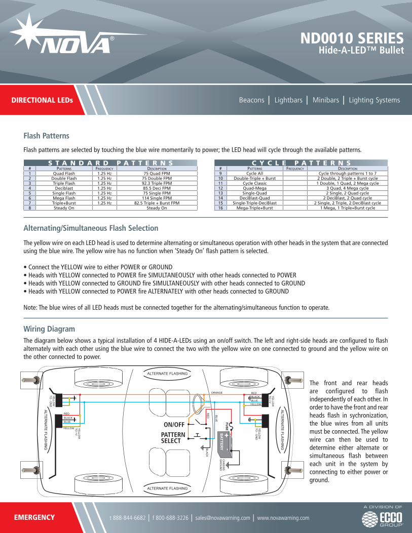
Wiring Diagram
Flash Patterns
Flash patterns are selected by touching the blue wire momentarily to power; the LED head will cycle through the available patterns.
The yellow wire on each LED head is used to determine alternating or simultaneous operation with other heads in the system that are connected using the blue wire. The yellow wire has no function when ‘Steady On’ flash pattern is selected.
• Connect the YELLOW wire to either POWER or GROUND• Heads with YELLOW connected to POWER fire SIMULTANEOUSLY with other heads connected to POWER• Heads with YELLOW connected to GROUND fire SIMULTANEOUSLY with other heads connected to GROUND• Heads with YELLOW connected to POWER fire ALTERNATELY with other heads connected to GROUND
Note: The blue wires of all LED heads must be connected together for the alternating/simultaneous function to operate.
The diagram below shows a typical installation of 4 HIDE-A-LEDs using an on/off switch. The left and right-side heads are configured to flash alternately with each other using the blue wire to connect the two with the yellow wire on one connected to ground and the yellow wire on the other connected to power.
The front and rear heads are configured to flash independently of each other. In order to have the front and rear heads flash in sychronization, the blue wires from all units must be connected. The yellow wire can then be used to determine either alternate or simultaneous flash between each unit in the system by connecting to either power or ground.
Alternating/Simultaneous Flash Selection
FUSE
ALTE
RN
ATE FLA
SH
ING
REDBLACKBLUE
YELLOW
YE
LLOW
TO +V
YE
LLOW
TO - G
ND
REDBLACKBLUE
YELLOW YE
LLOW
TO +V
YE
LLOW
TO - G
ND
ALTE
RN
ATE FLA
SH
ING
ALTERNATE FLASHING
ALTERNATE FLASHING
CH
AS
SIS
GR
OU
ND
RE
D
ORANGE
BLU
E
BLA
CK
PATTERN SELECT
ON/OFF