nov. 2007 malfunction diagnosis and toleranceslide 1 fault-tolerant computing dealing with mid-level...
Post on 21-Dec-2015
218 views
TRANSCRIPT
Nov. 2007 Malfunction Diagnosis and Tolerance Slide 1
Fault-Tolerant Computing
Dealing with Mid-Level Impairments

Nov. 2007 Malfunction Diagnosis and Tolerance Slide 2
About This Presentation
Edition Released Revised Revised
First Nov. 2006 Nov. 2007
This presentation has been prepared for the graduate course ECE 257A (Fault-Tolerant Computing) by Behrooz Parhami, Professor of Electrical and Computer Engineering at University of California, Santa Barbara. The material contained herein can be used freely in classroom teaching or any other educational setting. Unauthorized uses are prohibited. © Behrooz Parhami

Nov. 2007 Malfunction Diagnosis and Tolerance Slide 3
Malfunction Diagnosis and Tolerance

Nov. 2007 Malfunction Diagnosis and Tolerance Slide 4

Nov. 2007 Malfunction Diagnosis and Tolerance Slide 5
Multilevel Model of Dependable Computing
Component Logic Service ResultInformation System
Ide
al
De
fect
ive
Fa
ulty
Err
one
ou
s
Ma
lfun
ctio
nin
g
De
gra
de
d
Fa
iled
Level
Low-Level Impaired Mid-Level Impaired High-Level ImpairedUnimpaired
EntryLegend: Deviation Remedy Tolerance

Nov. 2007 Malfunction Diagnosis and Tolerance Slide 6
Self-DiagnosisLayered approach: A small part of a unit is tested, which then forms a trusted core The trusted core is used to test the next layer of subsystems Region of trust is gradually extended, until it covers the entire unit
One approach to go/no-go testing based on self-diagnosis Tester supplies a random seed to the built-in test routine The test routine steps through a long computation that exercises nearly all parts of the system, producing a final result The tester compares the final result to the expected result
Ideally, if a properly designed self-test routine returns a 32-bit value, the value will match the expected result despite the presence of faults with probability 2–32 10–9.6 test coverage = 1 – 10–9.6
CoreSelf-diagnosis initiation Unit A
Unit B
Unit C

Nov. 2007 Malfunction Diagnosis and Tolerance Slide 7
Malfunction Diagnosis ModelDiagnosis of one unit by another The tester sends a self-diagnosis request, expecting a response The unit under test eventually sends some results to the tester The tester interprets the results received and issues a verdict
Testing capabilities among units is represented by a directed graphi
Tester
j
Testee
Test capability
I think j is okay(passed test)
0
i
Tester
j
Testee
Test capability
I think j is bad(failed test}
1
The verdict of unit i about unit j is denoted by Dij {0, 1}All the diagnosis verdicts constitute the n n diagnosis matrix D The diagnosis matrix D is usually quite sparse
M0
M1M3
M2

Nov. 2007 Malfunction Diagnosis and Tolerance Slide 8
More on Terminology and AssumptionsMalfunction diagnosis in our terminology corresponds to “system-level fault diagnosis” in the literature
The qualification “system-level” implies that the diagnosable units are subsystems with significant computational capabilities (as opposed to gates or other low-level components)
We do not use the entries on the main diagonal of the diagnosis matrix D (a unit does not judge itself) and we usually do not let two units test one another
A good unit always issues a correct verdict about another unit (i.e., tests have perfect coverage), but the verdict of a bad unit is arbitrary and cannot be trusted
This is known as the PMC model (Preparata, Metze, & Chien)
We consider the PMC model only, but other models also exist(e.g., in comparison-based models, verdicts are derived from comparing the outputs of unit pairs)
-- D01 -- -- -- -- D12 D13
D20 -- -- -- D30 -- D32 --
Nov. 2007 Malfunction Diagnosis and Tolerance Slide 9
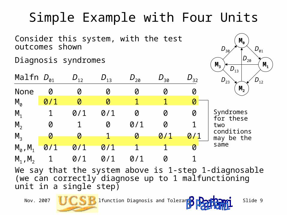
Syndromes for these two conditions may be the same
Simple Example with Four Units
Consider this system, with the test outcomes shown
We say that the system above is 1-step 1-diagnosable (we can correctly diagnose up to 1 malfunctioning unit in a single step)
M0
M1M3
M2
D01
D12
D30
D23
D20
D13
Diagnosis syndromes
Malfn D01 D12 D13 D20 D30 D32
None 0 0 0 0 0 0M0 0/1 0 0 1 1 0
M1 1 0/1 0/1 0 0 0
M2 0 1 0 0/1 0 1
M3 0 0 1 0 0/1 0/1
M0,M1 0/1 0/1 0/1 1 1 0
M1,M2 1 0/1 0/1 0/1 0 1
Nov. 2007 Malfunction Diagnosis and Tolerance Slide 10
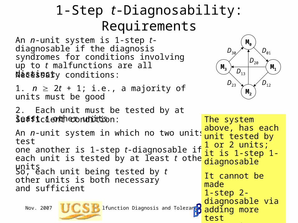
1-Step t-Diagnosability: Requirements
An n-unit system is 1-step t-diagnosable if the diagnosis syndromes for conditions involving up to t malfunctions are all distinct
Necessary conditions:
1. n 2t + 1; i.e., a majority of units must be good
2. Each unit must be tested by at least t other units
M0
M1M3
M2
D01
D12
D30
D23
D20
D13
Sufficient condition:
An n-unit system in which no two units test one another is 1-step t-diagnosable iff each unit is tested by at least t other units
The system above, has each unit tested by 1 or 2 units; it is 1-step 1-diagnosable
It cannot be made 1-step 2-diagnosable via adding more test connections
So, each unit being tested by t other units is both necessary and sufficient

Nov. 2007 Malfunction Diagnosis and Tolerance Slide 11
Analogy: “Liars and Truth-Tellers” Puzzles
You visit an island whose inhabitants are from two tribesMembers of one tribe (“liars”) consistently lieMembers of the other tribe (“truth-tellers”) always tell the truth
You encounter a person on the islandWhat single yes/no question would you ask him to determine his tribe?
More generally, how can you derive correct conclusions from info provided by members of these tribes, without knowing their tribes?
How would the problem change if the two tribes were “truth-tellers” and “randoms” (whose members give you random answers)
M0
M1M3
M2
0
0
x
x
0
1
In the context of malfunction diagnosis:Truth-tellers are akin to good modulesRandoms correspond to bad modulesYou do not know whether a module is good or badModule “opinions” about other modules must be used to derive correct diagnoses
Nov. 2007 Malfunction Diagnosis and Tolerance Slide 12
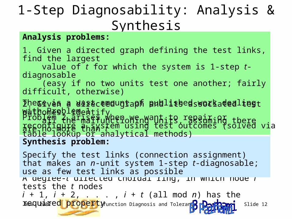
1-Step Diagnosability: Analysis & Synthesis
A degree-t directed chordal ring, in which node i tests the t nodes i + 1, i + 2, . . . , i + t (all mod n) has the required property
Synthesis problem:
Specify the test links (connection assignment) that makes an n-unit system 1-step t-diagnosable; use as few test links as possible
Analysis problems:
1. Given a directed graph defining the test links, find the largest value of t for which the system is 1-step t-diagnosable (easy if no two units test one another; fairly difficult, otherwise)
2. Given a directed graph and its associated test outcomes, identify all the malfunctioning units, assuming there are no more than t
There is a vast amount of published work dealing with Problem 1
Problem 2 arises when we want to repair or reconfigure a system using test outcomes (solved via table lookup or analytical methods)

Nov. 2007 Malfunction Diagnosis and Tolerance Slide 13
An O(n3)-Step Diagnosis Algorithm
Input: The diagnosis matrixOutput: Every unit labeled G or Bwhile some unit remains unlabeled repeat choose an unlabeled unit and label it G or B use labeled units to label other units if the new label leads to a contradiction then backtrack endifendwhile
M0
M1M3
M2
1
0
1
0
1
0
1-step 1-diagnosable system
M0 is G (arbitrary choice)M1 is BM2 is B (contradiction, 2 Bs)
M0 is B (change label)M1 is G M2 is GM3 is G
More efficient algorithms exist
Nov. 2007 Malfunction Diagnosis and Tolerance Slide 14
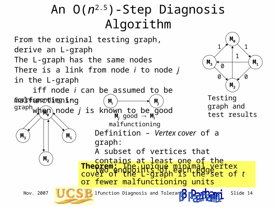
An O(n2.5)-Step Diagnosis Algorithm
From the original testing graph, derive an L-graphThe L-graph has the same nodesThere is a link from node i to node j in the L-graph iff node i can be assumed to be malfunctioning when node j is known to be good
M0
M1M3
M2
1
0
1
0
1
0
Theorem: The unique minimal vertex cover of the L-graph is the set of t or fewer malfunctioning units
Testing graph and test results
Mi Mj
Mj good Mi malfunctioning
Definition – Vertex cover of a graph: A subset of vertices that contains at least one of the two endpoints of each edge
M0
M1M3
M2
Corresponding L-graph
Nov. 2007 Malfunction Diagnosis and Tolerance Slide 15
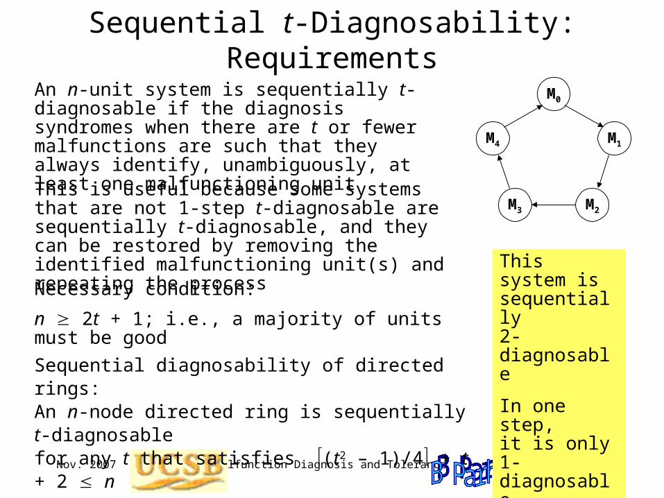
Sequential t-Diagnosability: Requirements
An n-unit system is sequentially t-diagnosable if the diagnosis syndromes when there are t or fewer malfunctions are such that they always identify, unambiguously, at least one malfunctioning unit
Necessary condition:
n 2t + 1; i.e., a majority of units must be good
This is useful because some systems that are not 1-step t-diagnosable are sequentially t-diagnosable, and they can be restored by removing the identified malfunctioning unit(s) and repeating the process
This system is sequentially 2-diagnosable
In one step, it is only 1-diagnosableSequential diagnosability of directed rings:
An n-node directed ring is sequentially t-diagnosable for any t that satisfies (t2 – 1)/4 + t + 2 n
M0
M1M4
M2M3
Nov. 2007 Malfunction Diagnosis and Tolerance Slide 16
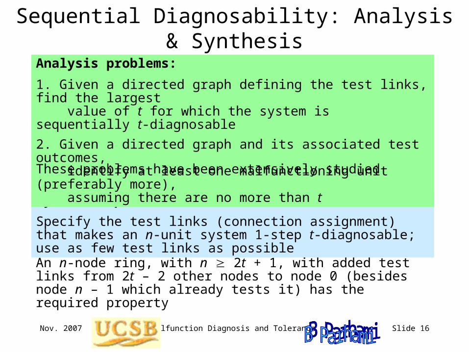
Sequential Diagnosability: Analysis & Synthesis
An n-node ring, with n 2t + 1, with added test links from 2t – 2 other nodes to node 0 (besides node n – 1 which already tests it) has the required property
Synthesis problem:
Specify the test links (connection assignment) that makes an n-unit system 1-step t-diagnosable; use as few test links as possible
Analysis problems:
1. Given a directed graph defining the test links, find the largest value of t for which the system is sequentially t-diagnosable
2. Given a directed graph and its associated test outcomes, identify at least one malfunctioning unit (preferably more), assuming there are no more than t
These problems have been extensively studied
Nov. 2007 Malfunction Diagnosis and Tolerance Slide 17
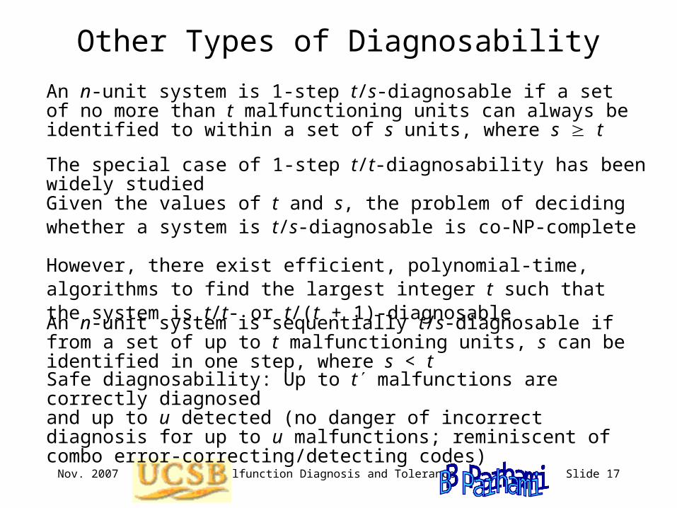
Other Types of Diagnosability
An n-unit system is 1-step t/s-diagnosable if a set of no more than t malfunctioning units can always be identified to within a set of s units, where s t
An n-unit system is sequentially t/s-diagnosable if from a set of up to t malfunctioning units, s can be identified in one step, where s < t
The special case of 1-step t/t-diagnosability has been widely studied
Given the values of t and s, the problem of deciding whether a system is t/s-diagnosable is co-NP-complete
However, there exist efficient, polynomial-time, algorithms to find the largest integer t such that the system is t/t- or t/(t + 1)-diagnosable
Safe diagnosability: Up to t malfunctions are correctly diagnosed and up to u detected (no danger of incorrect diagnosis for up to u malfunctions; reminiscent of combo error-correcting/detecting codes)

Nov. 2007 Malfunction Diagnosis and Tolerance Slide 18
What Comes after Malfunction Diagnosis?
When one or more malfunctioning units have been identified, the system must be reconfigured to allow it to isolate those units and to function without the unavailable resources
In a bus-based system, we isolate malfunctioning units, remove them, and plug in good modules (standby spares or repaired ones)
In a system having point-to-point connectivity, we reconfigure by rearranging the connections in order to switch in (shared) spares, using methods similar to those developed for defect circumvention
Reconfiguration may involve:
1. Recovering state info from removed modules or back-up storage2. Reassigning tasks and reallocating data3. Restarting the computation from last checkpoint or from scratch
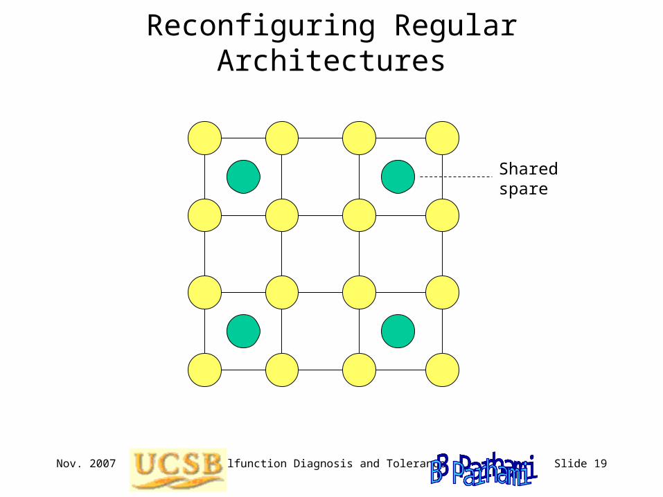
Nov. 2007 Malfunction Diagnosis and Tolerance Slide 19
Reconfiguring Regular Architectures
Sharedspare
Nov. 2007 Malfunction Diagnosis and Tolerance Slide 20
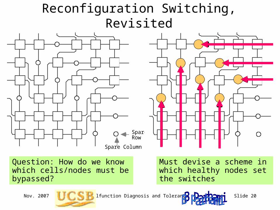
Reconfiguration Switching, Revisited
Spare Row
Spare Column
Question: How do we know which cells/nodes must be bypassed?
Must devise a scheme in which healthy nodes set the switches

Nov. 2007 Malfunction Diagnosis and Tolerance Slide 21
Diagnosability of Regular Structures
(a) 2D torus (b) 4D hypercube
(c) Chordal ring (d) Ring of rings
Diagnosability results have been published for a variety of regular interconnection networks

Nov. 2007 Malfunction Diagnosis and Tolerance Slide 22
Malfunction Tolerance with Low Redundancy
Reconfigurable 4 4 mesh with one spare
The following example scheme uses only one spare processor for a 2D mesh (no increase in node degree), yet it allows system reconfiguration to circumvent any malfunctioning processor, replacing it with the spare via relabeling of the nodes
0 1 2 3
4 5 6 7
8 9 10 11
12 13 14 15
11 12 13 14
15 0 1
2 3 4 5
6 7 8 9
10Spare
Malfn.