nottingham presentation advances in 3g and 4g mobile ... · comparison two military-controlled...
TRANSCRIPT

Nottingham Presentation
Presentation
By
Dr. S.V. Kibe
ISRO HQ
Bangalore, India
University of Nottingham
Nottingham, UK
May 17-18, 2010

Nottingham presentation: Part C
World developments in GNSS
Status of SATNAV Systems
• Principle of Positioning through one-way range
• GPS
• GLONASS
• Galileo
• GAGAN and IRNSS
• COMPASS
• QZSS
• Augmentations

REQUIREMENTS OF NAVIGATION AND POSITION
LOCATION SYSTEMS
• ALL WEATHER
• UNIVERSAL ACCESS
• MULTIMODAL
• CIVIL CONTROLLED
• MAINTAIN SOVEREIGNTY OF NATIONS
• HIGHEST SAFETY REQUIREMENTS
• HIGH REAL TIME POSITION ACCURACY
NAVIGATION AND POSITION LOCATION SYSTEMS STANDARDS ARE
DRIVEN BY CIVIL AVIATION

Global Positioning System
GPS


WGS-84 ELLIPSOID


Non-Precision Approach - 400 ft @ 4mi
Precision Approaches -Category I 200 ft @ .5mi
-Category II 100 ft @ .25mi
-Category III 50 ft @ .125 mDistance
to runway
Height
above terrain

SEPARATION OF ERRORS
ATMOSPHERIC ERROR - 3D
EPHEMERIC ERROR - 3D
CLOCK ERROR - 1D
WIDE AREA DIFFERENTIAL
TECHNIQUE

LNAV/VNAV (556 m by 50 m) - Baro VNAV
New APV-I (40 m by 50 m) - SBAS Avionics
APV-II (40 m by 20 m) - SBAS Avionics
Performance Comparison

COMPARISONTWO MILITARY-CONTROLLED OPERATIONAL
SATELLITE NAVIGATION SYSTEMS
GPS GLONASS
• > 30 SATELLITES 24 SATS BY 1996, 19 NOW
• 20,000 km. ALT. 19,000 km.
• L-BAND (20 MHz @ 1575.42 MHz L-BAND (23 MHz)
• ON-BOARD CLOCK MORE STABLE LESS STABLE
• 100 m H POS. ACC 100 m.
156 m. V POS. ACC
• 340 nsec TT ACC ~1 MICRO SEC
• CDMA FDMA/P-N CODE FOR
EACH S/C
• 7.5 to 10 YEARS S/C LIFE 5 YEARS FOR GLONASS M
• > $ 10 BILLION EST.>$10 BILLION
• WGS-84 ECEF PZ-90 ECEF

GPS Constellation Status
• 13 Block IIA satellites operational
• 12 Block IIR satellites operational
• 5 Block IIR-M satellites operational
– 4th IIR-(17)M successfully launched on 17 Oct 07
– Set healthy on 31 Oct 07
– 5th IIR-(17)M successfully launched on 21 Dec 07
– Set healthy on 3 Jan 08
• 3 additional satellites to launch through FY 2008
– IIR-(19)M in Mar 08
– IIR-(20)M in Jun 08
– IIR-(21)M in Sep 08
30 Healthy SatellitesBaseline Constellation: 24

Current GPS Accuracy• Signal-In-Space (SIS) User Range Error (URE)
– One-year RMS as of Jun 07: 0.95 meters
• Zero Age-Of-Data (AOD) URE
– One-year RMS as of Jun 07: 0.26 meters
Signal-in-Space User Range Error (SIS
URE) the difference between a GPS
satellite’s navigation data (position and
clock) and the truth, projected on the
line-of-sight to the user
URE

1575.421227.6
Frequency (MHz)
1176.45
-250
-240
-230
-220
Pow
er
Spectr
um
(dB
W/H
z)
1575.421227.6
-250
-240
-230
-220
Pow
er
Spectr
um
(dB
W/H
z)
Frequency (MHz)
1575.421227.6
Frequency (MHz)
1176.45
-250
-240
-230
-220
Pow
er
Spectr
um
(dB
W/H
z)
1575.421227.6
-250
-240
-230
-220P
ow
er
Spectr
um
(dB
W/H
z)
Frequency (MHz)
P(Y) C/A
L5
M
L2C
L1C
L1L2
L5
Block IIA/IIR, 1990
Block III, 2014
Block IIR-M, 2005
Block IIF, 2009
as of Dec 2005
(artist’s concept)
planned
previous
GPS Modernization – Spectrum
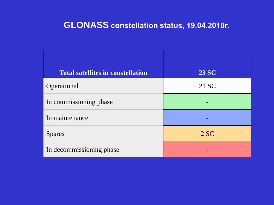
GLONASS constellation status, 19.04.2010г.
Total satellites in constellation 23 SC
Operational 21 SC
In commissioning phase -
In maintenance -
Spares 2 SC
In decommissioning phase -

Current values of position geometry factor PDOP on the Eath surface (the mask angle: 5°)

COVERAGE FROM 82 & 55 Deg.E

GPS Augmentation systems in the World
(For APV - 1.5 capability)
2008 2011? 2011?RNP 0.3
2012-13
GAGAN

100% less than 7.6m threshold value
Position Accuracy of GAGAN, BG- HYD Sortie on 18/09/2007

E6E5a E5E5b
L1
L5 L1
L3
LEX (E6)L5 L1
E6E5b L1
COMPASS
IRNSS
Compatibility & interoperability with other GNSS
GAGAN

E6E5a E5E5b
L1
L5 L1
L3
LEX (E6)L5 L1
E6E5b L1
COMPASS
IRNSS
Compatibility & interoperability with other GNSS
GAGAN
L5

GAGAN SPACE SEGMENT AVAILABILITY
• GAGAN FOP approved by the Indian Govt.
• The Department of Space has planned GAGAN L1 & L5 frequency payloads on GSAT-4, GSAT-8 & GSAT-9 satellites.The present schedules for these satellites are
1. GSAT-4 Launch by early 2010 on-board GSLV
2. GSAT-8 Launch by last quarter of 2010
3. GSAT-9 to be launched by second half of 2011. (GSAT-9 is planned to be an in-orbit spare.)
4. GSAT-10 planned to launched in 2011.

TDS CONFIGURATION FOR FSAT
Jammu
Ahamedabad
Delhi
Guwahati
Calcutta
Triuandrum
Port Blair
Bangalore
AR = Access Router
CR = Core Router
-DCN circuit lines
FES = Fast Ethernet Switch
AR #1
INRES
CR #1FES
#1
INMCC
AR #1
INRES
AR #1
INRES
AR #1
INRES
AR #1
INRES
AR #1
INRES
AR #1
INRES
AR #1
INRES
AR #1
INLUS
Jammu
Ahamedabad
Delhi
Guwahati
Calcutta
Triuandrum
Port Blair
Bangalore
AR = Access Router
CR = Core Router
-DCN circuit lines
FES = Fast Ethernet Switch
AR #1
INRES
AR #1
INRES
CR #1CR #1FES
#1
INMCC
AR #1
INRES
AR #1
INRES
AR #1
INRES
AR #1
INRES
AR #1
INRES
AR #1
INRES
AR #1
INRES
AR #1
INRES
AR #1
INRES
AR #1
INRES
AR #1
INRES
AR #1
INRES
AR #1
INRES
AR #1
INRES
AR #1
INLUS
AR #1
INLUS
Ground Segment
• 8 INRES: 2 INREEs
• 1 INMCC
• 1 INLUS
• 1 ring of OFC (7 INRES)
• 1 VSAT link (GPB)
Space Segment
• INMARSAT-4F1

ACCURACY TIMELINE FOR BANGALORE INRES During FSAT
FSAT RESULTS
BANGALORE (INREE-A) BANGALORE (INREE-B)
SBAS Position Error Date:13/08/2007,17:05 hrs
Place: NRSA Hyderabad using 532C Patch Ant
-10
-8
-6
-4
-2
0
2
4
6
8
10
128000 129000 130000 131000 132000 133000 134000 135000 136000
Time in GPS sec
Po
sit
ion
Err
or
in m
trs
Lat
Lon
Hight
SBAS Rx Performance During FSATSnap Shots of Availability Contour on
FSAT day (13-14 Aug 2007

IRNSS - An Overview

GEO at 34º E
GSO at 55º E GSO at 111º E
GEO at 132º E
GEO at 83º E
1 1
IRNSS Space Craft Control Centre
IRNSS TTC & Uplinking Stations
IRNSS Range and Integrity Monitoring Stations
IRNSS Timing Centre
CDMA Ranging Stations
Laser Ranging Station
IRNSS Navigation Centre
Data Communication Links
SCF
INC
CDMA
RangingCDMA
Ranging
IRIMS IRIMS
IRNSS Architecture
TT&C and
Nav. Uplink
TT&C and
Nav. UplinkIRNSS
User
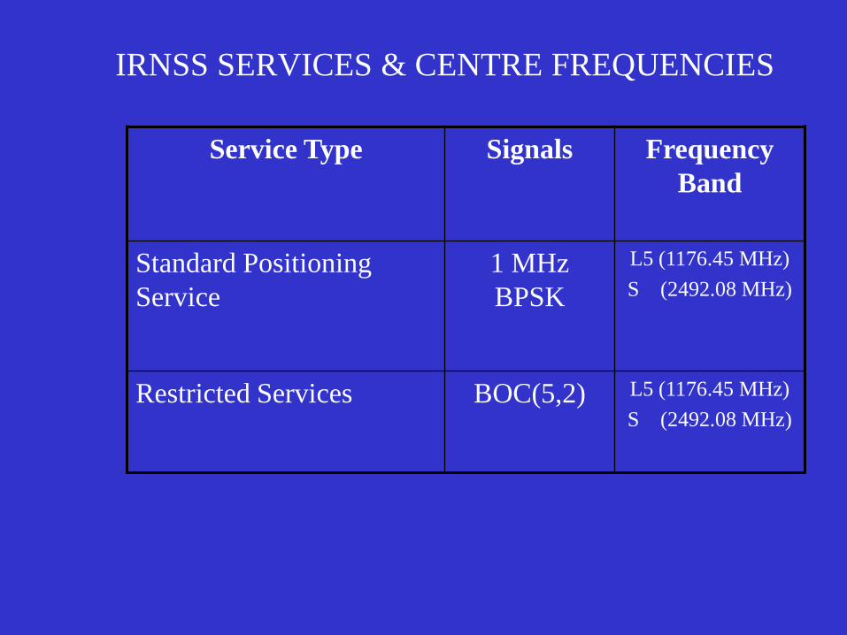
IRNSS SERVICES & CENTRE FREQUENCIES
Service Type Signals Frequency
Band
Standard Positioning
Service
1 MHz
BPSK
L5 (1176.45 MHz)
S (2492.08 MHz)
Restricted Services BOC(5,2) L5 (1176.45 MHz)
S (2492.08 MHz)

Navigation Signals –Fraction of power within Bandwidth
1 PSK
10 PSK
BOC(10,5)
BOC(10,2)
BOC(8,4)
BOC(5,2)
BOC(4,2)
BOC(2,1)
5 PSK
BOC(1,1)
Frequency Span: 0-30MHz


Data structure• Data structure for SPS and RS is the same and will include a
grid model. The clock, ephemeris, almanac data for 7 IRNSS
satellites is planned to be (?) transmitted with the same accuracy
as in legacy GPS, GLONASS & Galileo.
• Since the number of satellites in IRNSS are 7 as against 30 for
GPS, the field available for extra satellites is used up for
inserting a 80 grid points ionospheric model for the benefit of
single frequency user.
• Being discussed at present,Data structure similar to
augmentation, L2C/L5 systems and L1C is being further studied
( 33 bit ephemerides, message type structure, reduced almanac,
new coding etc).


Aggregate EPFD values computed during 4th & 5th RES-609 Consultaion
Meetings
-160-158-156-154-152-150-148-146-144-142-140-138-136-134-132-130-128-126-124-122-120
1164
1167
1170
1173
1176
1179
1182
1185
1188
1191
1194
1197
1200
1203
1206
1209
1212
1215
Frequency (MHz)
Agg.
EP
FD
(dB
W/m
2/M
Hz)
4th RES-609 CM 5th RES-609 CM (5deg) 5th RES-609 (1deg) ITU Limit
4th RES-609: -125.68dBW/m2/MHz, 5th RES-609(5deg): -122.46 dBW/m2/MHz, 5th RES-609(1deg): -122.34 dBW/m2/MHz

COMPASS – Technical description
• COMPASS consists of a constellation of 30 Non-
geostationary satellites and 5 geostationary satellites
at 58.75 deg.E, 80 deg.E, 110.5 deg.E, 140 deg.E
and 160 deg.E.
• COMPASS operations are centred around 1575.42
MHz, 1191.795 MHz and 1268.52 MHz.
• The geostationary satellites also use downlink in S-
band (2483.5 – 2500 MHz).
• The MEO constellation of COMPASS consists of 27
satellites in 3 orbital planes, inclined approx.55
deg.E to the equator and orbital altitude of 21500
kms.

COMPASS – Technical description (Contd.,)
• COMPASS signals in the L1 band uses BOC (14,2) modulation
(B signal). It is modulated with 50 bits/seconds/100
symbols/second navigation data. There is a pilot which is dataless
and is called B1P. The B1-C signal consists of two components in
phase quadrature. B1-CD is modulated with 100 symbols/sec
navigation data and B1CP is dataless. B1-CP represented by
)(33
4)(
33
29)( 1,61,1 fBOCfBOCfMBOC
)f(BOC)f(BOC)f(MBOC)f(BOC)f(S ,,, 16111111
1
11
10
4
3
4
1
The total psd of the B1-C components is given below:

COMPASS signals in the frequency
band 1 164-1 300 MHz
• COMPASS operates four signals in the 1 164-1 300 MHz
RNSS band. The signals include B2, B3 and B3-A.
• The COMPASS B2 signal is centred on a frequency of
1 191.795 MHz and is generated with an AltBOC
modulation of side-band sub-carrier rate of 15.345 MHz.
The power spectral density of the AltBOC signal is given
below:
• With is the subcarrier frequency, fc the chip rate,
Tc chip period and Tsc the period of the subcarrier.
2
4cos
2cos2
2cos
2cos
)/(cos
)(cos
2
1)( 2
2
2
22
scscscsc
c
c
c
Tf
Tf
Tf
Tf
nfT
fT
TffG
sc
sc
sc ff
T 1

COMPASS signals in the frequency band 1 164-
1 300 MHz (Contd)
• The B2 signal consists of two components in phase quadrature. One component, B2D, is modulated with a 50 bit/s/100 Symbol/s binary navigation data stream and the other, B2P, is dataless.
• The B3 signal is centred on 1 268.52 MHz. The carrier is QPSK modulated with a pseudo-random noise (PRN) codehaving a chip rate of 10.23 Mchip/s (in I channel or Q channel), which is Modulo-2 added to a 500 bit/s binary navigation data stream prior to modulation.
• The B3-A signal is also centred on 1 268.52 MHz, and uses a BOC(15,2.5) modulation. The B3-A signal consists of two components in phase quadrature. One component, B3-AD, is modulated with a 50 bit/s/100 Symbol/s binary navigation data stream and the other, B3-AP, is dataless.

Signal power and spectra
• The minimum received power level on the surface of the Earth, for
any elevation angle equal or more than 5°, based on an ideally
matched and isotropic 0 dBi receiver antenna are as follows:
B1 signal: −153.4 dBW for MEO network, −155.2 dBW for GSO/IGSO network.
B1-C signal: −156.4 dBW for MEO network,−158.2 dBW for GSO/IGSO network.
B2 signal: −153 dBW for MEO network,−154.8 dBW for GSO/IGSO network.
B3/B3-A signal: −156.5 dBW for MEO network,−158.3 dBW for GSO/IGSO network.


UK Data
The results of the aggregate epfd calculation for the above systems are
shown in the figure and table below.
1160 1170 1180 1190 1200 1210 1220145
140
135
130
125
120
Centre frequency (MHz)
agg
ep
fd (
dB
W/m
2.M
Hz)

Maximum RNSS Aggregate Epfd
per MHz
-140
-135
-130
-125
-120
1160 1170 1180 1190 1200 1210 1220
Center Frequency (MHz)
Max E
pfd
(d
B(W
/m²/
MH
z)
US Data

-145
-140
-135
-130
-125
-120
1164 1169 1174 1179 1184 1189 1194 1199 1204 1209 1214
Frequency (MHz)
Max
imum
agg
rega
te e
pfd
(dB
W/m
2/M
Hz)
Japan Data

Maximum Aggregate epfd
-145
-140
-135
-130
-125
-120
1164 1169 1174 1179 1184 1189 1194 1199 1204 1209 1214
Frequency, (MHz)
epfd
, (d
B(W
/m^2
)/M
Hz)
Maximum Aggregate epfd Limit =-121.5 (dB(W/m^2)/MHz)
Russian data

Maximum RNSS Aggregate epfd
-145
-140
-135
-130
-125
-120
1164 1169 1174 1179 1184 1189 1194 1199 1204 1209 1214
Frequency(MHz)
Aepfd
(dB
(W/m
²/M
Hz))
Res609 epfd Criterion
China data

MAXIMUM AGGREGATE EPFD
[INDIA WITH BEAM CENTRE (83,5) &
BOC(5,2) + 1 MHz BPSK]
-129
-128
-127
-126
-125
-124
-123
-122
-121
-120
1164 1169 1174 1179 1184 1189 1194 1199 1204 1209 1214
Frequency (MHz)
Ag
gre
gate
EP
FD
(d
B(W
/m2)/
MH
z)
1164 -128.17 1190 -127.95
1165 -128.3 1191 -127.86
1166 -128.39 1192 -127.89
1167 -128.33 1193 -127.86
1168 -128.07 1194 -127.53
1169 -127.57 1195 -126.82
1170 -126.78 1196 -125.98
1171 -125.82 1197 -125.31
1172 -125.23 1198 -125.17
1173 -124.66 1199 -125.6
1174 -123.97 1200 -126.29
1175 -123.45 1201 -126.68
1176 -122.35 1202 -126.35
1177 -123.26 1203 -125.71
1178 -123.57 1204 -125.06
1179 -124.06 1205 -124.98
1180 -124.51 1206 -124.52
1181 -125.1 1207 -123.49
1182 -126.14 1208 -124.34
1183 -126.94 1209 -125.5
1184 -127.6 1210 -125.66
1185 -128.09 1211 -126.27
1186 -128.34 1212 -126.87
1187 -128.38 1213 -127.17
1188 -128.27 1214 -126.7
1189 -128.11 1215 -125.91

LIST OF RNSS SYSTEMS USED FOR AGGREGATE EPFD
CALCULATIONS
RNSS NETWORK ADMN. SYSTEM IFIC
COMPASS -58.75E CHINA GSO 2420-2489
COMPASS -80E CHINA GSO 2420-2489
COMPASS –110.5E CHINA GSO 2420-2489
COMPASS – 140E CHINA GSO 2420-2489
COMPASS – 160E CHINA GSO 2512-2552
COMPASS – MHMG CHINA N-GSO 2513-2563
GLONASS-M RUSSIA N-GSO 2469
INMAR GSO-2N (64E) G GSO 2476-2507
INMAR GSO-2L(53W) G GSO 2453-1497
INMAR 4 – 25E G GSO 2504-2537
INMAR 4 – 143.5E G GSO 2504-2537
INMAR 4 – 98W G GSO 2527-2553

LIST OF RNSS SYSTEMS USED FOR AGGREGATE EPFD
CALCULATIONS (Contd.,)
RNSS NETWORK ADMN. SYSTEM IFIC
NAVSTAR GPS USA N-GSO 2479-2538
MSAT NAV 2 FRANCE N-GSO 2415-2490
NSAT HEO 2 JAPAN N-GSO 2490-2603
MTSAT-C-140E JAPAN GSO 2578-2595
MTSAT-C-140E JAPAN GSO 2578-2595
INSAT NAV A 34E INDIA GSO 2603
INSAT NAV A 83E INDIA GSO 2603
INSAT NAV A GS INDIA N-GSO 2603
INSAT NAV A 132E INDIA GSO 2603
INSAT NAV 55E INDIA GSO 2592
INSAT NAV 82 INDIA GSO 2510-2552
RPS 1 USA GSO 2482-2488

LIST OF RNSS SYSTEMS USED FOR AGGREGATE
EPFD CALCULATIONS (Contd)
RNSS NETWORK ADMN. SYSTEM IFIC
RPS 2 USA GSO 2482 - 2488
NIGCOMSAT 1G NIGERIA GSO 2546 - 2606

Thank-you