notice - videx, inc. replacement flashing led developers information pulsestar error codes and...
TRANSCRIPT


Notice:Videx, Inc. reserves the right to make improvements or changes in the productdescribed in this manual at any time without notice.
Limited Warranty:Videx, Inc. warrants this software package to be free from defects in materialand workmanship for a period of one year from the date of original purchase.Videx, Inc. assumes no responsibility for any special or consequential damages.
Disclaimer of All Warranties and Liability:Videx, Inc. makes no warranties, either expressed or implied except as explicitlyset forth in the Limited Warranty above, with respect to this manual nor withrespect to the product described in this manual, its quality, performance, mer-chantability, or fitness for any purpose. Videx, Inc. software is sold or licensed“as is.” The entire risk as to its quality and performance is with the buyer. Shouldthe programs prove defective following their purchase, the buyer assumes theentire cost of all necessary servicing, repair, or correction and any incidental orconsequential damages. In no event will Videx, Inc. be liable for direct, indirect,incidental, or consequential damages resulting from any defect or the possibilityof such damages. Some states do not allow the exclusion or limitation of impliedwarranties or liability for incidental or consequential damages, so the abovelimitation or exclusion may not apply to you.
Copyright Notice:This manual is copyrighted. All rights are reserved. This document may not, inwhole or in part, be copied, photocopied, reproduced, translated or reduced toany electronic medium or machine-readable form without prior consent, inwriting, from Videx, Inc.
PulseStar is a trademark of Videx, Inc. Videx is a registered trademark of Videx,Inc. All other trademarks are properties of their respective owners.
Copyright © 2000 by Videx, Inc.Part# MN-TPS-02 GCO# 1254
Videx, Inc., 1105 NE Circle Blvd., Corvallis, Oregon 97330Phone (541) 758-0521 Fax (541) 752-5285
www.videx.com

OverviewInstallation and Operation of PulseStar SystemPulseStar Base StationiButtonSoftware Installation
PulseStar PC SoftwareWindows
Transfer
iButtonMenus
FileEditSettingsHelp
Battery ReplacementFlashing LEDDevelopers Information
PulseStar Error Codes and Descriptions
Specifications
Configuration Options
Configure
.....................................................................................
...........................................................................................................................................................
......................................................................
...............................................................
.............................................................
........................................................................................................................
...............................................................
.........................................................................................................................
...........................................................................................................................................
..........................................................................
.....................................................................................................
..............................................................
................................144910
121417
18181820
2324
24
26
27
21
Table of Contents
..........................................................................Troubleshooting 25
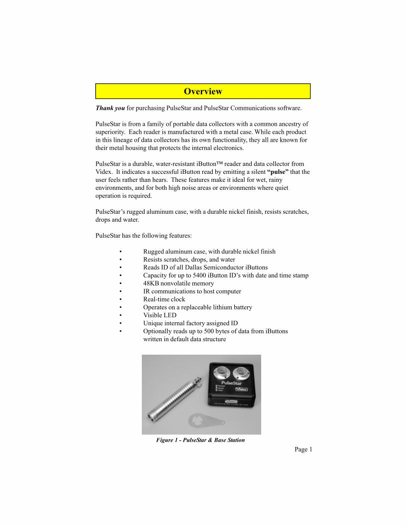
Thank you for purchasing PulseStar and PulseStar Communications software.
PulseStar is from a family of portable data collectors with a common ancestry ofsuperiority. Each reader is manufactured with a metal case. While each productin this lineage of data collectors has its own functionality, they all are known fortheir metal housing that protects the internal electronics.
PulseStar is a durable, water-resistant iButton™ reader and data collector fromVidex. It indicates a successful iButton read by emitting a silent “pulse” that theuser feels rather than hears. These features make it ideal for wet, rainyenvironments, and for both high noise areas or environments where quietoperation is required.
PulseStar’s rugged aluminum case, with a durable nickel finish, resists scratches,drops and water.
PulseStar has the following features:
• Rugged aluminum case, with durable nickel finish• Resists scratches, drops, and water• Reads ID of all Dallas Semiconductor iButtons• Capacity for up to 5400 iButton ID’s with date and time stamp• 48KB nonvolatile memory• IR communications to host computer• Real-time clock• Operates on a replaceable lithium battery• Visible LED• Unique internal factory assigned ID• Optionally reads up to 500 bytes of data from iButtons
written in default data structure
Page 1
Overview
Figure 1 - PulseStar & Base Station

Page 2
Overview
Full System Contents
1.) PulseStar reader2.) PulseStar Base Station (includes power transformer)3.) PulseStar Communications Software CD4.) iButtons5.) Serial cable (9-pin or 25-pin)
PC System Requirements
� Requires Windows® 95 or later, or Windows NT® Workstation 4.0 or later
� 32MB of RAM (64MB recommended)
� 5MB minimum hard drive space (20MB preferred to allow for data files and for installing Adobe Acrobat)
� 486 or faster processor (120MHz recommended, 350MHz desirable)
� Available serial port
� CD-ROM Drive for installation and to access technical reference material
Optional Accessory
Blue Dot reader and cable (BDR-000)

MemoryPulseStar has 48KB (K = 1024 characters) of memory. This is enough storagecapacity for 5400 iButton IDs (with time and date stamp) to be stored in memorybefore it is necessary to transfer the data to the computer.
When the PulseStar memory is full, it will not indicate successful reads and willinstead rapidly flash its LED. Memory is nonvolatile; the battery may beremoved but the memory contents are retained.
PulseStar contains a real-time clock that is set to match the computer’s clockeach time the unit is programmed or its data is transferred. For the PulseStarclock to be correct, the date and time on the computer must be set correctlybefore communicating with the PulseStar.
Clock
Overview
When an iButton is read successfully, the date and time is recorded along withthe entered data. This timekeeping feature makes it possible for you to use adatabase, spreadsheet, or other program to calculate beginning, ending, andintervals of time from data downloaded from the PulseStar.
The clock has a two-second resolution, and will operate up to one minute afterdisconnection from battery power.
Page 3

Page 4
To communicate with a computer using a PulseStar Base Station, insert thePulseStar into one of the Base Station’s slots (Figure 2). The Base Station mustbe connected to the computer’s serial port with either a 9-pin or 25-pin Videxserial port cable. See pages 5 – 7 for instructions on connecting the BaseStation to the computer. (Note: If the Base Station fails to communicate, reset itby unplugging it from the electric outlet and plugging it back in.)
Communication to the Computer
PulseStar communicates with the computer via an IR link, utilizing IrDA®technology. The PulseStar’s IR link is an IR transmitter recessed in the readhead. The computer’s IR link is a PulseStar Base Station. PulseStar establishestwo-way communication to the host computer using this IR link.
1.) PulseStar is ready for use the minute you receive it. To read an iButton,lightly press the PulseStar read head to an iButton. PulseStar willindicate a successful iButton read by emitting a silent “pulse.”
2.) Connect the base station to the PC using a serial cable and to powerusing the transformer. (See following section.)
3.) Install PulseStar Communications software. (Detailed instructionsstart on page 10.)
4.) Run PulseStar Communications software. PulseStar Communicationssoftware defaults to continually searching for the PulseStar oncommunication port 1. To change the default port setting, choose“Communications” from the “Settings” menu. A dialog box appearswhich allows you to change the communications port setting.
5.) To download the information the PulseStar has collected, placethe PulseStar into the base station. PulseStar Communications softwarewill locate, download, and update the data log of the PulseStar.
Installation and Operation of PulseStar System
PulseStar Base Station

The PulseStar Base Station provides communication between the PulseStar andthe computer. The base station has three LEDs: Transmit, Receive, and Power(Figure 3). The Transmit LED will illuminate when the PulseStar is sendinginformation to the computer. The Receive LED will illuminate when thecomputer is sending information to the PulseStar. The Power LED willilluminate when the base station is plugged into an electric power outlet.
PulseStar Base Station
The Computer port, Power connection, and Extension port are located on theside of the base station (Figure 4). The Computer port is where the computer’sserial port cable connects to the base station. The Power connection is wherethe power transformer plugs into the base station. The Extension port allowsyou to connect up to ten base stations to a single computer serial port. Thisallows you to transfer data from more than two PulseStars during a singletransfer process.
Figure 4 - PulseStar Base Station - Side View
Figure 3 - Base Station LEDs
Figure 2 - PulseStar Base Station
Page 5

Page 6
1. Shut down the computer.
2. Plug the Base Station’s power transformer (Output: 12 VDC 300 mA) intoan electric outlet.
3. Plug the other end of the transformer cable into the Power socket on theside of the Base Station. See Figure 4.
4. Verify that the Power light on the Base Station is lit.
5. Connect the serial port cable’s connector (9-pin or 25-pin) to yourcomputer’s serial port. You can use com ports 1, 2, 3, or 4. (Note: The serialports on a DOS/Windows computer are always a male connector. Pin-outsfor the Videx serial port cables are provided on the software CD.)
6. Connect the serial port cable’s RJ-11 plug to the Computer port of the BaseStation.
7. The Base Station must be placed at least three inches away from thecomputer and monitor to prevent the possibility of high levels of electro-magnetic interference hindering communications.
The following steps describe how to connect a PulseStar Base Station to thecomputer’s serial port. You will need a computer, PulseStar Base Station, and aVidex serial port cable (TWC-001 (DB25) or TWC-008 (DB9)).
Figure 5 - PulseStar Base Station Connections
Connecting the Base Station to a Computer

Figure 6 - Base Stations in Series
Up to 10 Videx Base Stations, holding 20 PulseStars, can be connected in seriesto a single serial port; this allows the user to transfer data from multiple datacollectors in a single transfer process. You can transfer data from up to 20 unitsat a time. Note: The additional base stations are powered from the first one, sono additional power transformers are required in most cases.
Connecting the Base Stations
To connect multiple Base Stations:1) Connect the first Base Station to the computer’s serial port:
a) Plug the Base Station’s transformer into an electric outlet and connect theother end into the Base Station’s Power connection.
b) Use the serial port cable to connect the computer’s serial port to theBase Station’s Computer port.
c) The Base Station should be placed at least three inches away from thecomputer and monitor.
2) To add additional Base Stations:a) Use an interconnect cable (TWC-006) to connect the Extension port of
the first Base Station to the Computer port on the second Base Station.b) Continue the same pattern of connection for each additional unit.
Page 7
Using Multiple PulseStar Base Stations

Page 8
If you should inadvertently remove a PulseStar while it is in the process oftransferring data, the software displays a message that it was unable tocommunicate with the unit and then continues to try to transfer the data from allof the other PulseStars. The data in the interrupted unit will not clear and can betransferred after the others have completed their data transfer.
To avoid problems when using multiple Base Stations, you need to be aware ofthe following caution:
Caution:
When transferring data from the PulseStars, do not interrupt the process byremoving a PulseStar from its Base Station or aborting the program. Thesystem is designed to avoid data loss, but observing this caution providesadded protection.
Using Multiple PulseStar Base Stations

An iButton (also known as an Touch Memory Button) is a memory chip housedin a stainless steel container. The stainless steel container protects the memorychip and also provides an electrical path for communication. The top of thebutton is connected to the enclosed memory chip circuit, and the bottom andsides of the button provide a signal ground. When a PulseStar touches aniButton, the top and the sides of the button are connected and an electrical path isestablished. Through this path, data is transferred at up to 16,000 bits per second.
All iButtons contain a unique serial number (12 hexadecimal digits) that isprogrammed into the button at the factory. The serial number is unalterable anduniquely identifies each button.
The PulseStar reads the ID number in all iButtons. Optionally you can configurethe PulseStar to read data written to buttons in Dallas default data structure fromthe following iButtons: 1982, 1985, 1986, 1992, 1993, and 1994. In addition tothe iButton ID number, the data stored in the iButton’s memory can be trans-ferred from the iButton to the PulseStar. This option is OFF by default and mustbe enabled with PulseStar Communications software.
Page 9
iButton
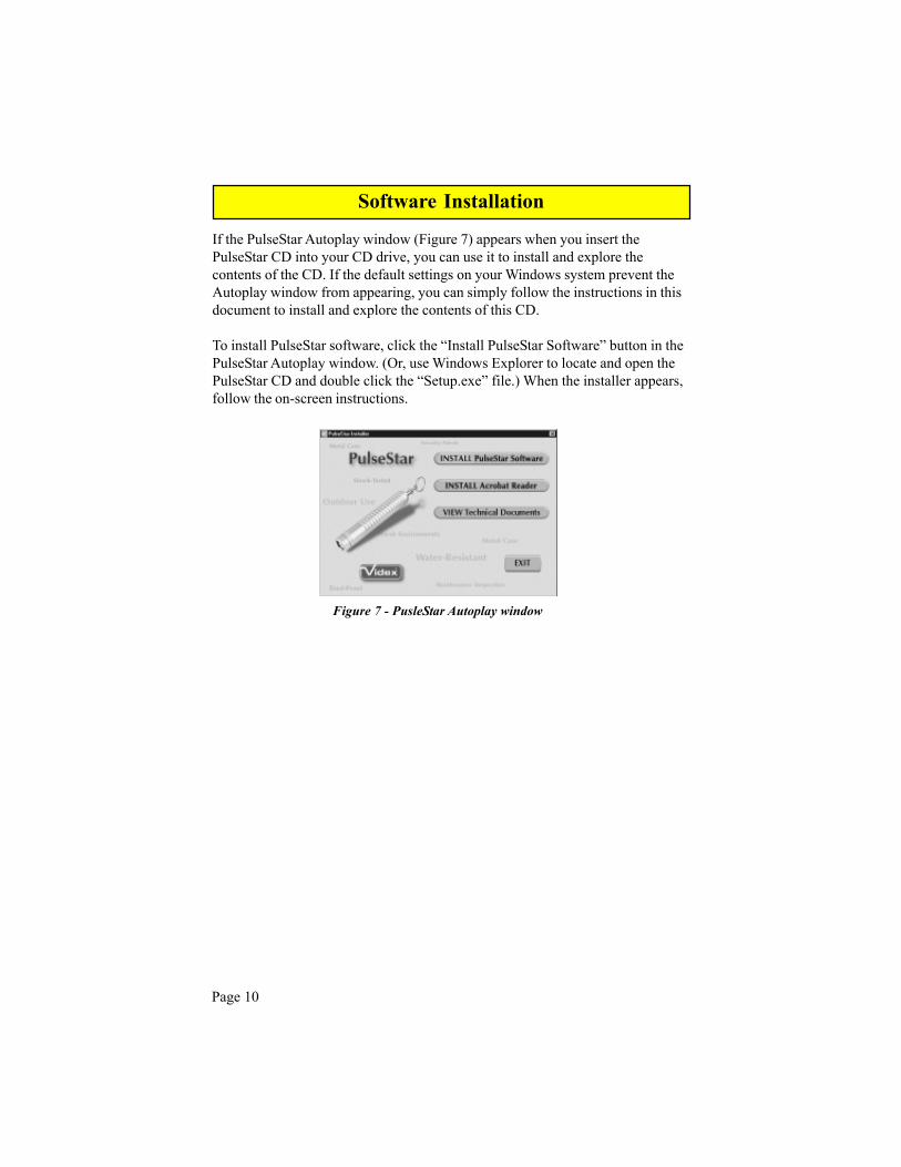
If the PulseStar Autoplay window (Figure 7) appears when you insert thePulseStar CD into your CD drive, you can use it to install and explore thecontents of the CD. If the default settings on your Windows system prevent theAutoplay window from appearing, you can simply follow the instructions in thisdocument to install and explore the contents of this CD.
To install PulseStar software, click the “Install PulseStar Software” button in thePulseStar Autoplay window. (Or, use Windows Explorer to locate and open thePulseStar CD and double click the “Setup.exe” file.) When the installer appears,follow the on-screen instructions.
Figure 7 - PusleStar Autoplay window
Page 10
Software Installation
Getting Started
Start PulseStar Communications by selecting Programs and then PulseStarCommunications from the Windows Start menu. When PulseStarCommunications first starts, it will attempt to use COM1 on your computer. IfCOM1 is not available, it will display the message “Unable to Open COM1” inthe status bar at the bottom of the window.
To use a different COM port, choose “Communications” (F2) from the “Set-tings” menu, and select one of the four available COM ports as your DataTransfer Serial Port. Then click OK. If “Looking for PulseStar on COMx” doesnot appear in the status bar, then from the “Settings” menu, choose “Look forPulseStar” to start the process. The Receive light on the PulseStar Base Stationshould now be lit.
Now insert a PulseStar into the base station. PulseStar Communications will findit, configure it, and add it to the list of PulseStars in the Configuration tab. Ifthere is any data it will transfer it, clear the data from the PulseStar, set thePulseStar’s clock, and display the data in the Transfer tab. It will also add anyiButtons to the list in the iButtons tab that are not already there.
Page 11

Transfer Tab
This tab shows data transferred from the PulseStar. In this window you may sortor filter the data, then export or print it. Click on column headers to sort. (Note:Cannot sort on iButton data.) Data can be filtered by “Factory ID,” “Name orSerial Number,” or “iButton Name or ID.” To filter data, first highlight the fieldto be filtered by single clicking on it. Then if you double click on that cell,filtered data will appear in the Transfer window.
To return the view to showing all data, double click on any of the column headerfields.
Tab headings:
Factory ID - Unique ID of PulseStarName or Serial Number - User-defined serial number or name for
PulseStar
Figure 8 - Transfer Tab
Name and location of data fileStatus of communications with PulseStar
Page 12
PulseStar PC Software - Tab Windows

Date and Time - Date and time of iButton readiButton Name or ID - iButton ID readiButton Data - Data retrieved from iButton. To read this
data, first highlight the iButton data field bysingle clicking on it. Then if you doubleclick on that field, the iButton data will bedisplayed (Figure 9).
Figure 9 - iButton Data
Page 13
PulseStar PC Software - Tab Windows
FacilityNameAcmeWarehouseFacilityOwnedByAcmeIncFacilityHasFourEntriesFacilityAddressOnePlazaPlaceLaurenceHarborNewJerseyFacilityRestrictionsNoEmployeeEntryAfterSevenPMFacilityEmergencyPrimaryContactJamesWhiteSecondaryContactMikeBrownFacilityLocatedInDistrictFiveFacilityChemicalHazardCodeOneFacilityLockDownTwoCorporateManagersNeedToAuthorizeFacilityOpeningAfterLockDown

Configure Tab
This tab shows the list of PulseStars in your system, the name or serial numberassigned to them, and the last date and time of communications. New PulseStarsare automatically added to the list when they are encountered by the communica-tions software. To assign a name or enter the serial number, simply type in thedesired name. The transfer grid will automatically update to show the changes.
Tab headings & buttons:
Factory ID - Unique ID of PulseStarName or Serial Number - User defined name or serial numberLast Communications - Date and time of last communication
Figure 10 - Configure Tab
Page 14
PulseStar PC Software - Tab Windows

Delete button - Remove PulseStar from list.
Advanced button - Brings up the list of settings to program into the PulseStarthe next time it is encountered. When a PulseStar is new, it is configured to thefour settings shown in Figure 11.
Duration of “good read” pulse – This tells the PulseStar how long to runits motor to indicate that an iButton has been read and recorded. Thefactory default is 1000 milliseconds (1 second). Since the “good read”pulse is the largest current draw in the system, increasing this value couldsignificantly reduce battery life. Conversely, decreasing the duration couldimprove battery life, particularly if reading more than 50 iButtons daily.Increasing the duration of the pulse also effectively reduces the number ofiButtons that can be read in a short period of time because PulseStar cannotread an iButton while it is pulsing. PulseStar Communications softwareautomatically sets it to 500 milliseconds (1/2 second) at its firstcommunications.
“Good read” pulse intensity – This setting increases or decreases the dutycycle of the motor. The factory setting of 5 represents a 50% duty cycle.Increasing the “Good read” pulse intensity to 10 (or 100% duty cycle)effectively doubles the current draw of the motor and could significantlyreduce battery life.
Delay before recording ID of same iButton – Since the PulseStar will readand record iButton ID’s very quickly, it is likely to read and record aniButton more than once when you only intended to record it once. Thissetting imposes a delay in 2 second increments that gives you some time toremove the reader from the iButton after the iButton ID is recorded in thePulseStar’s memory and the PulseStar emits its pulse. This delay is notimposed when you read iButtons with different IDs.
Figure 11 - Advanced Configurations
Page 15
PulseStar PC Software - Tab Windows

Set As Default button – Takes the settings from the current window andstores them as the default.
The following pop-up appears:
Unless you choose otherwise, all PulseStars in the system will be updated tothe new default settings when they are encountered.
Restore Default button – Retrieves your stored defaults from memory andwrites them to the fields in the window.
Attempt to read data from iButtons – The PulseStar can read and recorddata from iButtons written in the Dallas default data structure. Since thisfunction adds to the overall iButton reading time, it is turned off by defaultbut may be enabled by toggling this control.
Figure 12 - Set As Default
Figure 13 - PulseStar Status
Status button - displays the configuration settings read from the PulseStarduring its most recent communications.
Page 16
PulseStar PC Software - Tab Windows

iButton Tab
This tab displays a list of iButtons in your system. To assign a name or descrip-tion to an iButton, simply type in a name. The Transfer grid will automaticallyupdate with the new name. iButtons not in the list will be automatically enteredinto the list during communications. If you wish to add iButtons from the Editmenu, choose “Manually Add iButton” to type into the entry form (Figure 15).Alternatively you can use the Blue Dot reader to manually add iButtons. TheBlue Dot reader is an optional accessory. Before using the Blue Dot reader,
Figure 14 - iButton Tab
Status of communications with Blue Dotreader
Figure 15 - Manually Add iButton
Page 17
PulseStar PC Software - Tab Windows
Tab headings:
iButton ID - Unique factory IDiButton Name - User-defined name
make sure that the correct serial port has beenselected for this device. (From the Settingsmenu, choose Communications, and thenselect an iButton reader serial port.)

File MenuNew - Create new data fileOpen - Open existing data fileSave As - Save as Access database file (*.mdb) or as text file
(*.txt)Print Setup - Standard print setupPrint - Standard print optionsExit - End program
Edit MenuCut - Future useCopy - Future usePaste -Future useRemove Record(s) - Removes record(s) (Transfer and
Configuration screens)Remove iButton - Removes iButton from iButton screenManually Add iButton - Allows user to add iButtons manually
Settings MenuCommunications
Data Transfer Serial Port - Select the communicationport to which the base station is physically attached.
Blue Dot Reader Serial Port - Select the communication portto which the iButton Reader cable is physically attached.
PulseStar Settings -Clear PulseStar data after transfer (Default)Set PulseStar clock after transfer - Update each PulseStar afterdownload is complete. (Default)Warn if battery voltage drops below threshold - Allows user toset low battery voltage threshold. (Default 2.51V)
Figure 16 Communications OptionsPage 18
PulseStar PC Software - Drop-Down Menus

Raw Scan File
Look for PulseStar - When this menu option is checked, the softwarecontinually searches for the PulseStar for data transfer.
Figure 17 Raw Scan File Options
Output to Videx raw data file in addition to writing to the database -This option allows the software to create a Videx raw data file inaddition to the database file (.mdb) that is created automatically.This option is provided to allow compatibility with previouslyexisting applications. Contact Videx Customer Service for moreinformation.
Data File Name - Allows user to select location and name of datafile.
Replace iButton ID with iButton data when there is data read fromthe iButton - When this option is checked, the PulseStar will readthe data that has been written to the iButton’s memory instead of theID of the button, and write it to the raw scan file.
Data Indentation - Select Spaces, Tab, or None - This option allowsuser to select what type of indentation will be used in the data file.
Page 19
PulseStar PC Software - Drop-Down Menus

Help MenuAbout - Version of PulseStar Software
Figure 18 - About PulseStar Communications
Page 20
PulseStar PC Software - Drop-Down Menus

The PulseStar is shipped with a 3V lithium battery. The life of this battery insleep (storage) mode is up to 1 year or up to 40,000 reads when using defaultsettings. Exact battery life depends upon actual use.
To replace the battery, remove the battery cap using the spanner wrenchprovided with the PulseStar (Figure 19).
CAUTION:To help insure data integrity, download the PulseStar prior tochanging the battery. The system is designed to avoid data loss, butobserving this caution provides added protection.
Unscrew the battery cap counterclockwise. Replace the old battery with a newone, replace the battery cap, and tighten until snug. The new battery should beinstalled with the positive terminal facing toward the PulseStar read head(Figure 20). Replacement batteries are available in most photography outlets.
Figure 19 - PulseStar Spanner Wrench
Figure 20 - Battery Installation
Page 21
PulseStar Battery Replacement

Both the PulseStar reader and PulseStar Communications software provide alow battery warning. The warning is triggered when the measured batteryvoltage drops below a threshold. If it does, the PulseStar’s LED stops flashingand, if enabled, the PC will post a warning after completing communicationswith the PulseStar.
By default, the threshold voltage is 2.51, but it may be adjusted if desired. Youmay select from 2.19, 2.35, 2.51, 2.66, and 2.82 volts. The new threshold isprogrammed into each PulseStar at its next communication session.
The following chart provides an estimate of the days of battery life for PulseStar;it assumes that the PulseStar will be used 9 hours in a day, then downloaded andput into sleep mode. The PulseStar pulse duration is set at 1000 milliseconds(1 second) when it is shipped from the factory. PulseStar Communicationssoftware automatically sets it to 500 milliseconds (1/2 second) at itsfirst communications.
Page 22
PulseStar Battery Information
PulseStar Low Battery Level Warning

A light-emitting diode in the read head of the PulseStar is a status indicator. Thefollowing light patterns indicate the corresponding status:
1 flash every2.3 seconds
PulseStar battery level is above the low threshold, and itis checking every flash for a communications signalfrom the PC.
Double flash every4.6 seconds
PulseStar battery level is above the low threshold, but itis not checking for communications from the PC. Thisis the low power sleep mode set by the PC after datatransfer.
Steady on PulseStar infrared communications circuit is powered onand is ready to communicate with the PC. Typically thismode is invoked by the PC software, but it may also beinvoked by reading the same iButton 10 times in a row.The next button touch turns off the IR circuit and theLED.
Off PulseStar battery level is below the low threshold orPulseStar is nonfunctional.
Page 23
PulseStar Flashing LED

Please refer to the technical documents included on the PulseStarCommunications CD.
ErrorNumber Error Text
1000 "No error has occurred."
1001 "An attempt to allocate or reallocate memory failed."
1002 "An attempt to access a file failed."
1003 "An attempt to manipulate a comm port failed."
1004 "A synchronization error occurred while attempting to communicate with a button reader."
1005 "The function was interrupted by user input."
1006 "An invalid PulseStar ID was detected."
1007 "An invalid command was sent to the PulseStar."
1008 "No data is available."
1009 "A time-out occurred."
1010 "A bad bit value was specified for the PulseStar configuration bit variable."
1011 "No data is available."
1012 "Attempt to synchronize with the PulseStar failed."
1013 "One or more parameters contained an illegal value."
1014 "An error of unknown type occurred."
Page 24
Developers
PulseStar Error Codes and Descriptions

If you have problems with your PulseStar system, try the followingtroubleshooting tips. If you continue to have problems, contact Videx CustomerService by phone at (541)758-0521, by fax at (541)752-5285, or by e-mail [email protected].
My computer will not download data from the PulseStar.
1.) If the status bar at the bottom of the PulseStar window displays “Unableto Open Comx,” then the serial port may be in use by another programor device. To free up the serial port for use by the PulseStar, disable thatprogram or device.
2.) If the status bar displays “PulseStar Communications are idle,” from the“Settings” drop-down menu, be sure that “Look for PulseStar” ischecked.
3.) If the status bar displays “Looking for PulseStar on Comx” or “Unableto Open Comx,” make sure that the correct serial port has been selected.You can change the serial port by clicking on “Settings” and thenselecting “Communications.”
4.) If the status bar displays “Looking for PulseStar on Comx,” try cleaningthe outside surface of the PulseStar’s IR link (the recessed circular areain the read head). If dust or debris accumulates here, it can interferewith the PulseStar’s ability to communicate. A Q-tip or similar item canbe used to clean this area.
5.) If the status bar displays “Looking for PulseStar on Comx,” be sure thatthe PulseStar is firmly seated in the downloader.
6.) If the PulseStar LED is not flashing, replace the battery.
Page 25
PulseStar Troubleshooting
Page 26
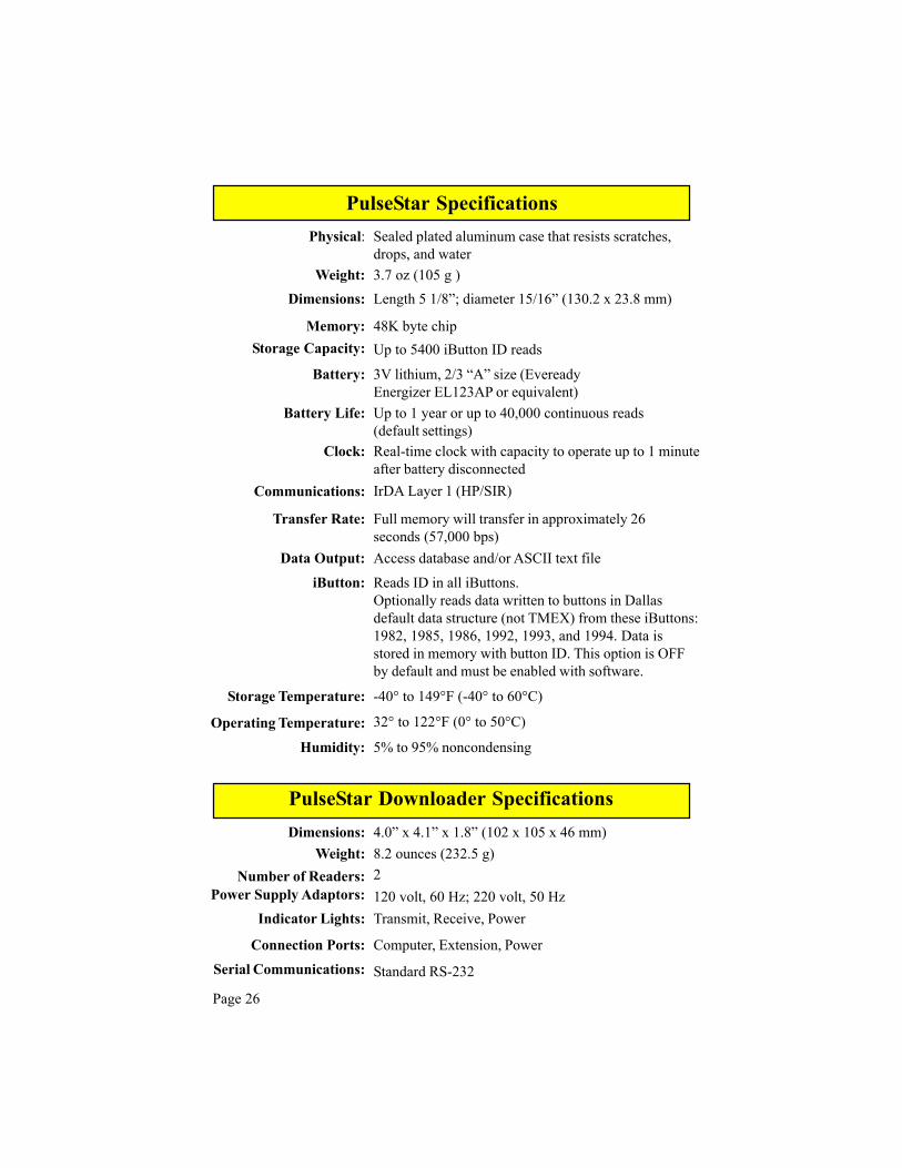
5% to 95% noncondensing
Physical:
Weight:Dimensions:
Memory:Storage Capacity:
3.7 oz (105 g )Length 5 1/8”; diameter 15/16” (130.2 x 23.8 mm)
48K byte chipUp to 5400 iButton ID reads
Battery: 3V lithium, 2/3 “A” size (EvereadyEnergizer EL123AP or equivalent)
Battery Life: Up to 1 year or up to 40,000 continuous reads(default settings)
Clock: Real-time clock with capacity to operate up to 1 minuteafter battery disconnected
Communications: IrDA Layer 1 (HP/SIR)
Transfer Rate: Full memory will transfer in approximately 26seconds (57,000 bps)
Data Output: Access database and/or ASCII text file
iButton: Reads ID in all iButtons.Optionally reads data written to buttons in Dallasdefault data structure (not TMEX) from these iButtons:1982, 1985, 1986, 1992, 1993, and 1994. Data isstored in memory with button ID. This option is OFFby default and must be enabled with software.
Storage Temperature: -40° to 149°F (-40° to 60°C)
Operating Temperature: 32° to 122°F (0° to 50°C)
Humidity:
Sealed plated aluminum case that resists scratches,drops, and water
Dimensions:Weight:
Number of Readers:Power Supply Adaptors:
Indicator Lights:
Connection Ports:Serial Communications:
4.0” x 4.1” x 1.8” (102 x 105 x 46 mm)8.2 ounces (232.5 g)2120 volt, 60 Hz; 220 volt, 50 HzTransmit, Receive, Power
Computer, Extension, Power
Standard RS-232
PulseStar Specifications
PulseStar Downloader Specifications

Page 27
Read RAM in iButton:
Motor running time (Read/Write):
Motor duty cycle (Read/Write):
Time between automatic IrDAsync retries:
Time attempting to sync:
Turn off ability to wake up byshorting contact:
0 - 12 seconds (default 1000milliseconds) PC software callsthis Duration of “good read”pulse. Allows range of 100 -1000 ms. NOTE: 0 - 1 secondadjustable through PulseStarCommunications Software.
1 - 10 (default 5 which is 50%) PCsoftware presents this as “Good read”pulse intensity.
0 to 586 seconds (default 2.3seconds)
1 - 255 ms (default 10 ms)
On - Off (default On)
On -Off (default Off) This optionincreases read time on all buttonsif enabled.
Refer to “Data Communications DLL Specification for PulseStar” document forinformation regarding additional settings. Technical documents can be locatedon the PulseStar Communications CD.
PulseStar Configuration Options
DLL Settings

Copyright © 2000 by Videx, Inc.Part# MN-TPS-02 GCO# 1254
Videx, Inc., 1105 NE Circle Blvd., Corvallis, Oregon 97330Phone (541) 758-0521 Fax (541) 752-5285
www.videx.com