notice - portal (tamir ba… · lock washers/plates and cotter pins ..... .. 1-3 bearings and oil...
TRANSCRIPT
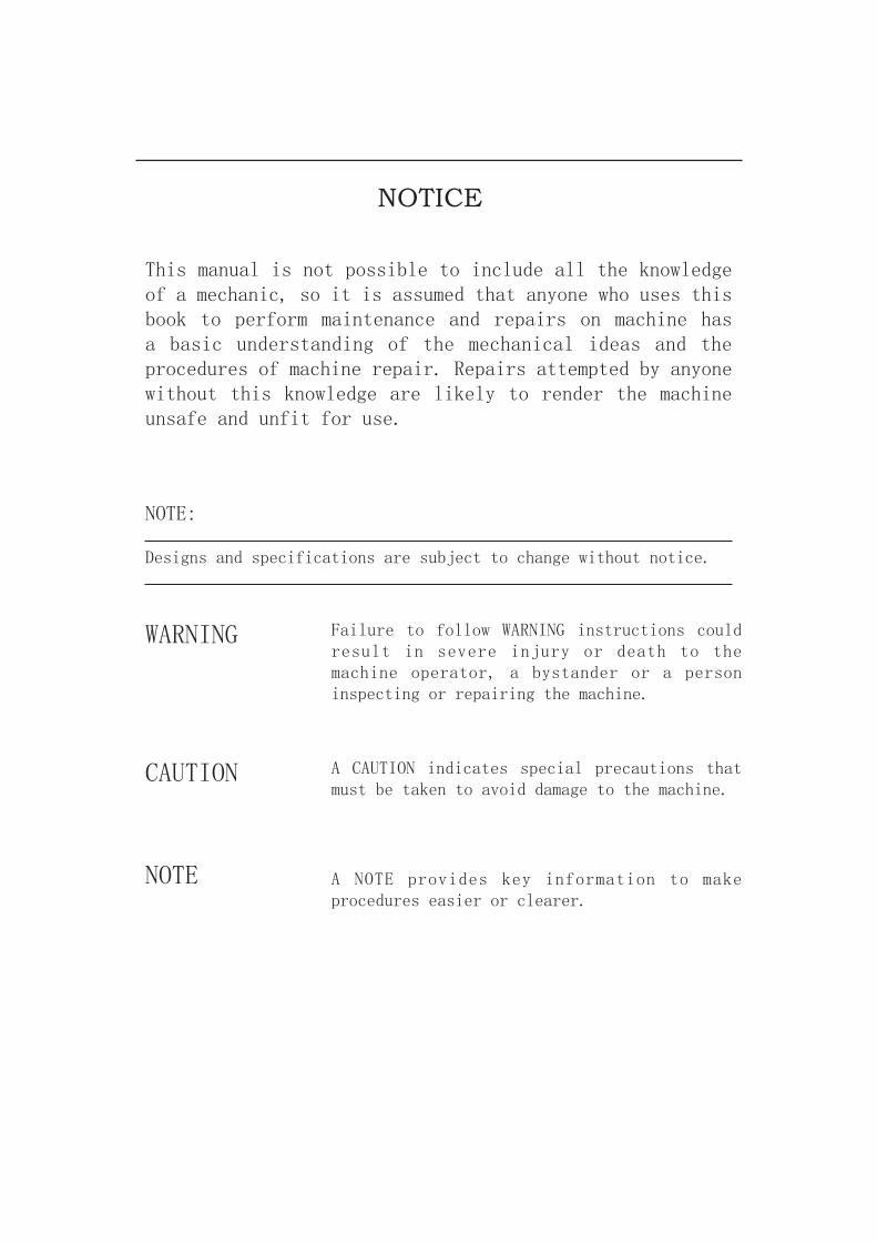
NOTICE
This manual is not possible to include all the knowledge of a mechanic, so it is assumed that anyone who uses this book to perform maintenance and repairs on machine has a basic understanding of the mechanical ideas and the procedures of machine repair. Repairs attempted by anyone without this knowledge are likely to render the machine unsafe and unfit for use.
NOTE:
Designs and specifications are subject to change without notice.
WARNING Failure to follow WARNING instructions could result in severe injury or death to the machine operator, a bystander or a person inspecting or repairing the machine.
CAUTION A CAUTION indicates special precautions that must be taken to avoid damage to the machine.
NOTE A NOTE provides key information to make procedures easier or clearer.

CHAPTER 1.GENERAL INFORMATION
MACHINE IDENTIFICATION ........................................................................ 1-1VEHICLE IDENTIFICATION NUMBER ................................................. 1-1MODEL LABEL ...................................................................................... 1-1IMPORTANT INFORMATION ....................................................................... 1-2PREPARATION FOR REMOVAL PROCEDURES ............................... 1-2REPLACEMENT PARTS ....................................................................... 1-2GASKETS, OIL SEALS AND O-RINGS ................................................ 1-2LOCK WASHERS/PLATES AND COTTER PINS ................................. 1-3BEARINGS AND OIL SEALS ................................................................ 1-3CIRCLIPS .............................................................................................. 1-3CHECKING OF CONNECTIONS .................................................................. 1-4SPECIAL TOOLS .......................................................................................... 1-5


1-1
GENERAL INFORMATION
MACHINE IDENTIFICATION
The vehicle identification number is stamped into the left side of the frame.
1-2
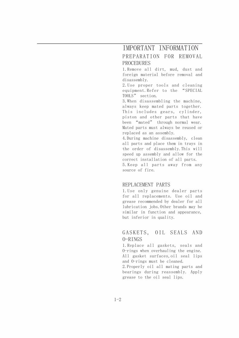
IMPORTANT INFORMATIONPREPARATION FOR REMOVAL PROCEDURES1.Remove all dirt, mud, dust and foreign material before removal and disassembly.2.Use proper tools and cleaning equipment.Refer to the “SPECIAL TOOLS” section.3.When disassembling the machine, always keep mated parts together. This includes gears, cylinder, piston and other parts that have been “mated” through normal wear.Mated parts must always be reused or replaced as an assembly.4.During machine disassembly, clean all parts and place them in trays in the order of disassembly.This will speed up assembly and allow for the correct installation of all parts.5.Keep all parts away from any source of fire.
REPLACEMENT PARTS1.Use only genuine dealer parts for all replacements. Use oil and grease recommended by dealer for all lubrication jobs.Other brands may be similar in function and appearance, but inferior in quality.
GASKETS, OIL SEALS AND O-RINGS1.Replace all gaskets, seals and O-rings when overhauling the engine. All gasket surfaces,oil seal lips and O-rings must be cleaned.2.Properly oil all mating parts and bearings during reassembly. Apply grease to the oil seal lips.

1-3
LOCK WASHERS/PLATES AND COTTER PINS1.Replace all lock washers/plates ① and cotter pins after removal. Bend lock tabs along the bolt or nut flats after the bolt or nut has been tightened to specification.
BEARINGS AND OIL SEALS1.Install bearings and oil seals so that the manufacturer’s marks or numbers are visible.When installing oil seals, apply a light coating of lightweight lithium base grease to the seal lips. Oil bearings liberally when installing, if appropriate.① Oil seal
CAUTION:Do not use compressed air to spin the bearings dry. This will damage the bearing surfaces.① Bearing
CIRCLIPS1.Check all circlips carefully before reassembly.Always replace piston pin clips after one use. Replace distorted circlips. When installing a circlip ① , make sure that the sharpedged corner ② is positioned opposite the thrust ③ it receives. See sectional view.④ Shaft
1-4
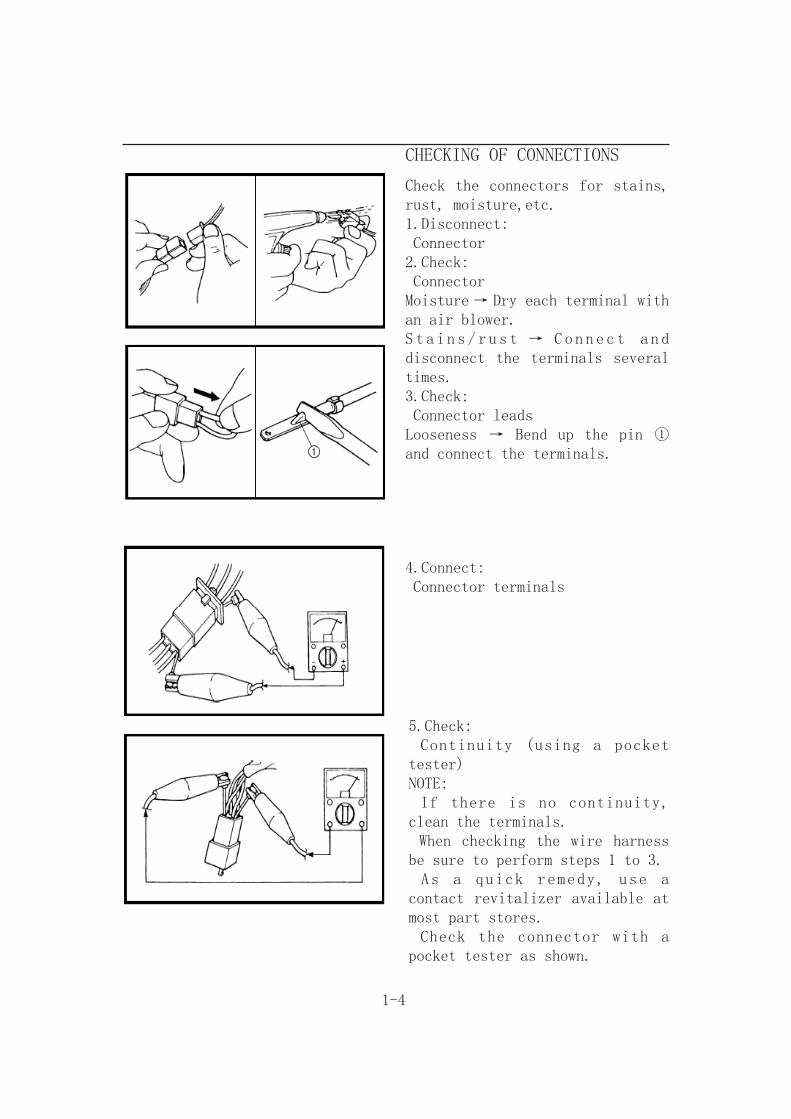
CHECKING OF CONNECTIONS
Check the connectors for stains, rust, moisture,etc.1.Disconnect: Connector2.Check: ConnectorMoisture → Dry each terminal with an air blower.S t a i n s / r u s t → Conn e c t a n d disconnect the terminals several times.3.Check: Connector leadsLooseness → Bend up the pin ① and connect the terminals.
4.Connect: Connector terminals
5.Check: Continuity (using a pocket tester)NOTE: If there is no continuity, clean the terminals. When checking the wire harness be sure to perform steps 1 to 3. As a quick remedy, use a contact revitalizer available at most part stores. Check the connector with a pocket tester as shown.

1-5
SPECIAL TOOLS
The following special tools are necessary for complete and accurate tune-up and assembly. Use only the appropriate special tools; this will help prevent damage caused by the use of inappropriate tools or improvised techniques.
Tool name/How to use Illustration
Slide hammer bolt (M6)/weight/setThese tools are used to remove the rocker arm shaft.
Crankcase separating toolThis tool is used to separate the crankcase.
Crankshaft installer potCrankshaft installer boltThese tools are used to install the crankshaft.
Crankshaft installer setThese tools are used to install the crankshaft.
AdapterSpacer (crankshaft installer)These tools are used to install the crankshaft.
SpacerThis tool is used to install the crankshaft.

1-6
Tool name/How to use Illustration
Piston pin pullerThis tool is used to remove the piston pin.
Tappet adjusting tool (3 mm)This tool is necessary for adjusting the valve clearance.
Fuel level gaugeThis gauge is used to measure the fuel level in the float chamber.
Radiator cap testerThis tool is used to check the cooling system.
AdapterThis tool is used to check the cooling system.
Damper rod holder (30 mm)This tool is needed to loosen and tighten the steering stem bearing retainer.
Flywheel pullerThese tools are needed to remove the rotor.
1-7
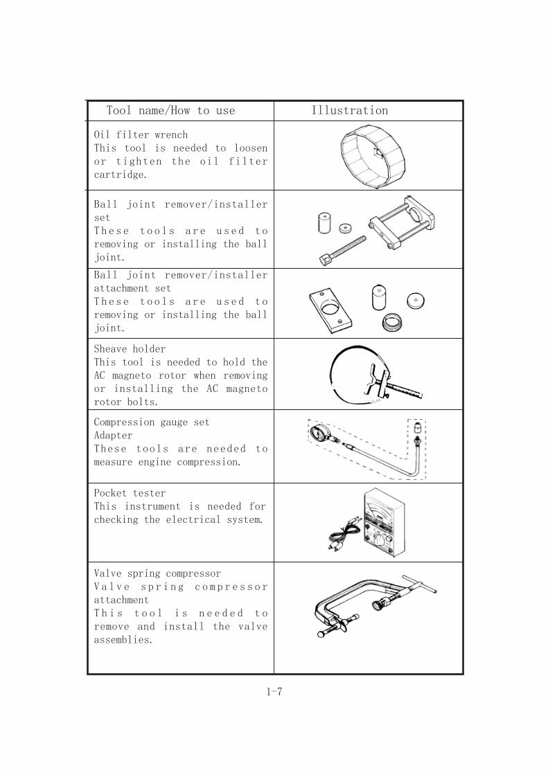
Tool name/How to use Illustration
Oil filter wrenchThis tool is needed to loosen or tighten the oil filter cartridge.
Ball joint remover/installer setT h e s e t o o l s a r e u s e d t o removing or installing the ball joint.
Ball joint remover/installer attachment setT h e s e t o o l s a r e u s e d t o removing or installing the ball joint.
Sheave holderThis tool is needed to hold the AC magneto rotor when removing or installing the AC magneto rotor bolts.
Compression gauge setAdapterThese tools are needed to measure engine compression.
Pocket testerThis instrument is needed for checking the electrical system.
Valve spring compressorV a l v e s p r i n g c o m p r e s s o r attachmentT h i s t o o l i s n e e d e d t o remove and install the valve assemblies.
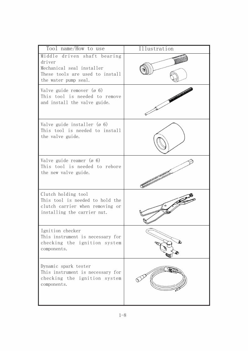
1-8
Tool name/How to use IllustrationMiddle driven shaft bearing driverMechanical seal installerThese tools are used to install the water pump seal.
Valve guide remover (ø 6)This tool is needed to remove and install the valve guide.
Valve guide installer (ø 6)This tool is needed to install the valve guide.
Valve guide reamer (ø 6)This tool is needed to rebore the new valve guide.
Clutch holding toolThis tool is needed to hold the clutch carrier when removing or installing the carrier nut.
Ignition checkerThis instrument is necessary for checking the ignition system components.
Dynamic spark testerThis instrument is necessary for checking the ignition system components.

2-1
SPECIFICATIONSGENERAL SPECIFICATIONS
Item Standard
Dimensions:Overall length 1890 mm Overall width 1050 mm Overall height 1120 mm Seat height 760 mm Wheelbase 1160 mm Minimum ground clearance 155 mm Minimum turning radius 2380 mm
Basic weight:With oil and full fuel tank 210 kg
Engine:Engine type Liquid-cooled Air cooled,4-strokeCylinder arrangement Forward-inclined single cylinderDisplacement 176 cm3Bore × stroke 62 × 58.4 mm Compression ratio 9.2 : 1Starting system Electric starter
Lubrication system: Force and splash
Oil type or grade:
API service SE, SF, SG type or higher
Oil capacity:Engine oilPeriodic oil change 1.9 LWith oil filter replacement 1.95 L Total amount 2.3 L Radiator capacity 1.3 L
Air filter: Wet type element
Fuel:Type Unleaded fuelFuel tank capacity 9 L
Transmission: Semi-automatic

2-2
Tire:Type TubelessSize front AT22 × 7–10rear AT22 × 10–10
Tire pressure (cold tire):Maximum load* 150 kgOff-road riding front 27.5 kPa (0.275 kg/cm2, 4.0 psi) rear 27.5 kPa (0.275 kg/cm2, 4.0 psi)*Load in total weight of cargo, rider and accessories
Brake: Front brake type Dual disc brake operation Right hand/Right foot operation Rear brake type Single disc brake operation Right foot operation
Suspension: Front suspension Double wishbone Rear suspension Swingarm (link suspension)
Shock absorber: Front shock absorber Coil spring Rear shock absorber Coil spring
Electrical: Ignition system DC-C.D.I. Generator system A.C. magneto Battery capacity 12 V 9 Ah
Bulb voltage/wattage × quantity: Headlight 12 V 30 W/30 W × 2 Tail/brake light 12 V 5 W/21 W × 1Indicator and warning lights Neutral 12 V 1.7 W × 1 Reverse 12 V 1.7 W × 1

HOW TO USE THE CONVERSIONTABLE
All specification data in this manual are listed in SI and METRIC UNITS.Use this table to convert METRIC unit data to IMPERIAL unit data.
2-3
Ex.METRIC MULTIPLIER IMPERIAL** mm × 0.03937 = ** in2 mm × 0.03937 = 0.08 in
CONVERSION TABLE
METRIC TO IMPERIALMetric unit Multiplier Imperial
unit
Torquem·kgm·kgcm·kgcm·kg
7.23386.7940.07230.8679
ft·lbin·lbft·lbin·lb
Weight kgg
2.2050.03527
lboz
Speed km/hr 0.6214 mph
Distancekmmmcmmm
0.62143.2811.0940.39370.03937
miftydinin
Volume/Capacity
cc (cm3)cc (cm3)lt (liter)lt (liter)
0.035270.061020.87990.2199
oz(IMP liq.)cu·inqt(IMP liq.)gal(IMP liq.)
Misc. kg/mmkg/cm2Centigrade(° C)
55.99714.22349/5+32
lb/inpsi (lb/in2)Fahrenheit (° F)
GENERAL TORQUESPECIFICATIONSThis chart specifies torque for standard fasteners with standard I.S.O. pitch threads. Torque s p e c i f i c a t i o n s f o r s p e c i a l components or assemblies are provided for each chapter of this manual. To avoid warpage, tighten multifastener assemblies in a crisscross fashion, in progressive stages, until the specified torque is reached. Unless otherwise specified, torque specifications r e q u i r e c l e a n , d r y t h r e a d s . Components should be at room temperature.
A: Distance between flatsB: Outside thread diameter
10 mm 6 mm 6 0.6 4.3
12 mm 8 mm 15 1.5 11
14 mm 10 mm 30 3.0 22
17 mm 12 mm 55 5.5 40
19 mm 14 mm 85 8.5 61
22 mm 16 mm 130 13.0 94
A(nut)
B(bolt)
General torquespecifications
Nm m•kg ft•lb

2-4
LUBRICATION POINTS AND LUBRICANT TYPESENGINE
Lubrication points Lubricant type
Oil seal lips (all)
O-ring (all)
Bearings (all)
Crank pin
Connecting rod (bearing)
Camshaft sprocket
Crankshaft
Piston surface/piston rings
Piston pin
Primary drive gear/primary driven gear
Valve stem/valve stem end
Rocker arm shaft
Rocker arm
Camshaft lobe/journal
Oil pump shaft, rotor, housing
Oil filter O-ring
Starter idle gear/shaft
Transmission gear (wheel/pinion)
Axle (main/drive)
Shift fork/guide bar
Shift drum/shift shaft/shift cam stopper ball
Shift lever/shift guide
① ② ③
④ ⑤ ⑥ ⑦
① Apply engine oil② Apply gear oil③ Apply molybdenum disulfide oil④ Apply wheel bearing grease⑤ Apply lightweight lithium soap base grease⑥ Apply molybdenum disulfide grease⑦ Apply silicon grease

3-1
PERIODIC CHECKS AND ADJUSTMENTSINTRODUCTION
This chapter includes all information necessary to perform recommended inspections and adjustments.These preventive maintenance procedures, if followed, will ensure more reliable vehicle operation and a longer service life. The need for costly overhaul work will be greatly reduced. This information applies to vehicles already in service as well as to new vehicles that are being prepared for sale. All service technicians should be familiar with this entire chapter.
PERIODIC MAINTENANCE/LUBRICATION INTERVALS
ITEMInitial Every
1 Month 3 Month 6 Month 6 Month 1 Year
Fuel Line 3 3 3
Spark Plug 1,3 1,3 1,3 1,3 1,3
Carburetor 3 3 3 3 3
A i r F i l t e r Element
Every 15-35 hours (more often in wet or dusty areas). Clean and replace if necessary.
Valves 3 3 3 3
Drive Chain 2,3 2,3 2,3 2,3 2,3
Battery 1,3 1,3 1,3 1,3 1,3
Nut Bolt,Fasteners 3 3 3 3 3
Wheels 3 3 3 3
Steering System 3 3 3 3 3
Brake 3 3 3 3 3
Oil Strainer 1,3 1,3 1,3 1,3 1,3
Wheel Bearing 2,3 2 2,3 2,3 2,3
Knuckle Shafts/Steering Shaft 2 2 2
1=clean2=lubricate3=adjust,inspect,replace if necessary.

NOTE
Recommended brake fluid: DOT 4 Brake fluid replacement:1.When disassembling the master cylinder or caliper cylinder, replace the brake fluid.Normally check the brake fluid level and add fluid as required.2.On the inner parts of the master cylinder and caliper cylinder, replace the oil seals every two years.3.Replace the brake hoses every four years, or if cracked or damaged.
WARNING
Indicates a potential hazard that could result in serious injury or death.
3-2
3-3
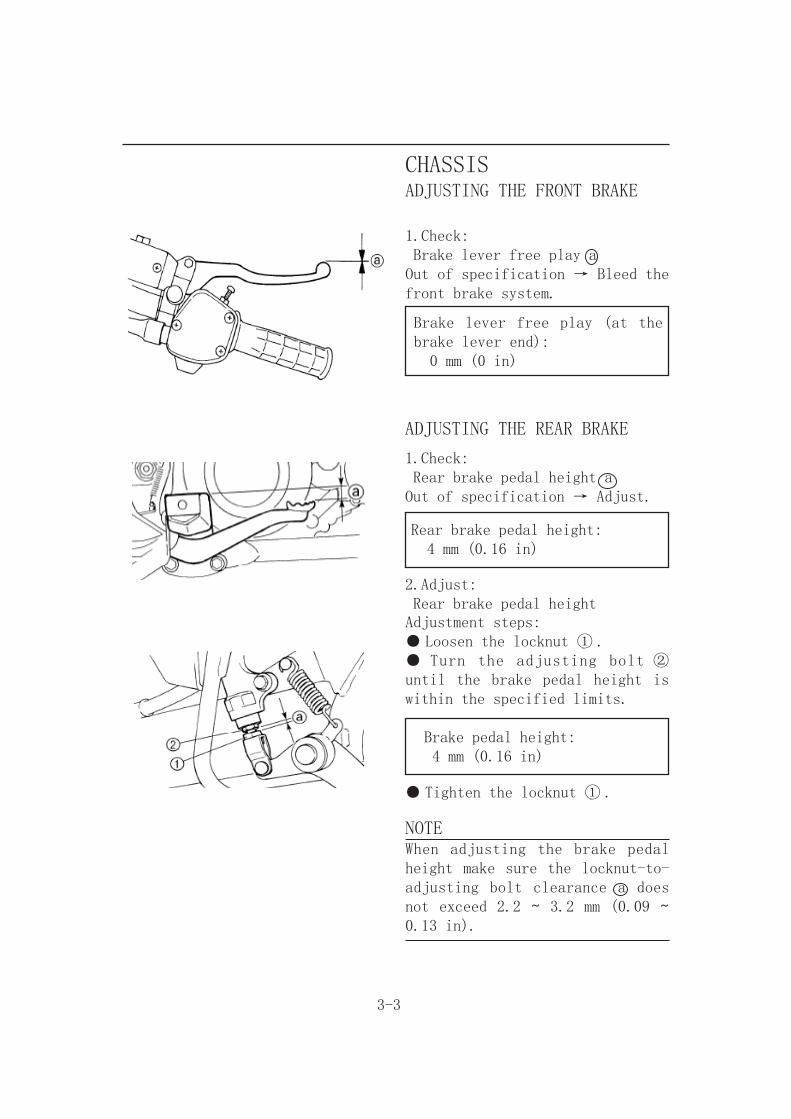
CHASSISADJUSTING THE FRONT BRAKE
1.Check: Brake lever free play aOut of specification → Bleed the front brake system.
Brake lever free play (at the brake lever end): 0 mm (0 in)
ADJUSTING THE REAR BRAKE
1.Check: Rear brake pedal height aOut of specification → Adjust.
Rear brake pedal height: 4 mm (0.16 in)
2.Adjust: Rear brake pedal heightAdjustment steps:● Loosen the locknut ① .● Turn the adjusting bolt ② until the brake pedal height is within the specified limits.
Brake pedal height: 4 mm (0.16 in)
● Tighten the locknut ① .
NOTEWhen adjusting the brake pedal height make sure the locknut-to-adjusting bolt clearance a does not exceed 2.2 ~ 3.2 mm (0.09 ~ 0.13 in).
3-4
WARNINGA f t e r t h i s a d j u s t m e n t i s performed, lift the rear wheels off the ground by placing a block under the engine, and spin the rear wheels to ensure there is no brake drag. If any brake drag is noticed perform the above steps again.
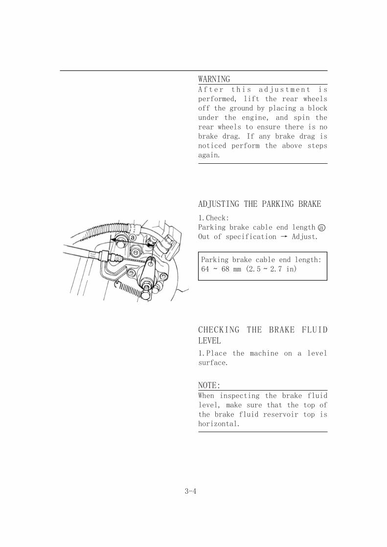
ADJUSTING THE PARKING BRAKE
1.Check:Parking brake cable end length aOut of specification → Adjust.
Parking brake cable end length:64 ~ 68 mm (2.5 ~ 2.7 in)
CHECKING THE BRAKE FLUID LEVEL
1.Place the machine on a level surface.
NOTE:When inspecting the brake fluid level, make sure that the top of the brake fluid reservoir top is horizontal.
3-5
2.Check: Brake fluid levelFluid level is below the “LOWER” level line → Add the recommended brake fluid to the proper level.
Recommended brake fluid: DOT 4
CAUTION:Brake fluid may erode painted surfaces or plastic parts. Always clean up spilled fluid immediately.
WARNING● Use only the designated quality brake fluid: Otherwise, the rubber seals may deteriorate, causing leakage and poor brake performance.● Refill with the same type of brake fluid:Mixing fluids may result in a harmful chemical reaction and lead to poor performance.● Be careful that water does not enter the master cylinder when refilling. Water will significantly lower the boiling point of the fluid and may result in a vapor lock.
3-6
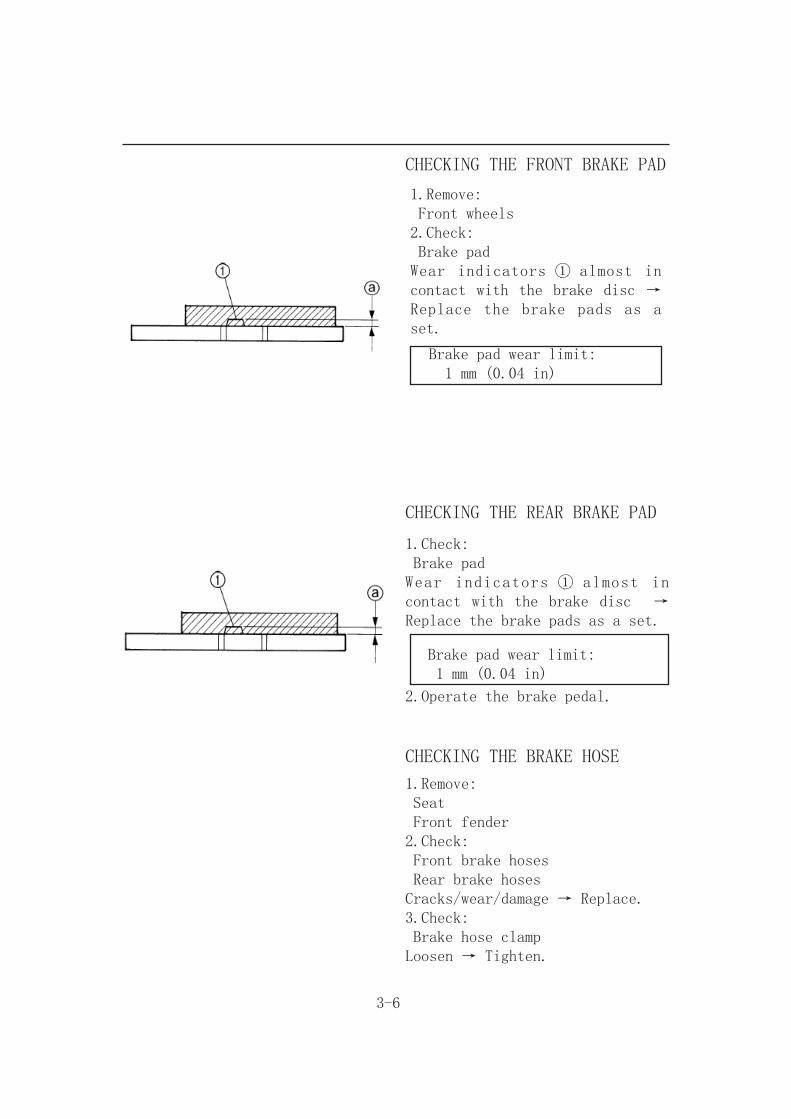
CHECKING THE FRONT BRAKE PAD
1.Remove: Front wheels2.Check: Brake padWear indicators ① almost in contact with the brake disc → Replace the brake pads as a set.
Brake pad wear limit: 1 mm (0.04 in)
CHECKING THE REAR BRAKE PAD
1.Check: Brake padWear indicators ① almost in contact with the brake disc → Replace the brake pads as a set.
Brake pad wear limit: 1 mm (0.04 in)
2.Operate the brake pedal.
CHECKING THE BRAKE HOSE
1.Remove: Seat Front fender2.Check: Front brake hoses Rear brake hoses Cracks/wear/damage → Replace.3.Check: Brake hose clampLoosen → Tighten.

4.Hold the machine in an upright position and apply the front or rear brake.5.Check: Brake hosesApply the brake lever several times.Fluid leakage → Replace the hose.6.Install: Front fender Seat
BLEEDING THE HYDRAULIC BRAKESYSTEM
WARNINGBleed the brake system if: T h e s y s t e m h a s b e e n disassembled. A brake hose or brake pipe have been loosened or removed. The brake fluid has been very low. The brake operation has been faulty.A loss of braking performance may occur if the brake system is not properly bled.
1.Bleed: Brake system
3-7
Air bleeding steps:a.Add the proper brake fluid to the reservoir.b.Install the diaphragm. Be careful not to spill any fluid or allow the reservoir to overflow.c.Connect the clear plastic hose ① tightly to the caliper bleed screw ② .
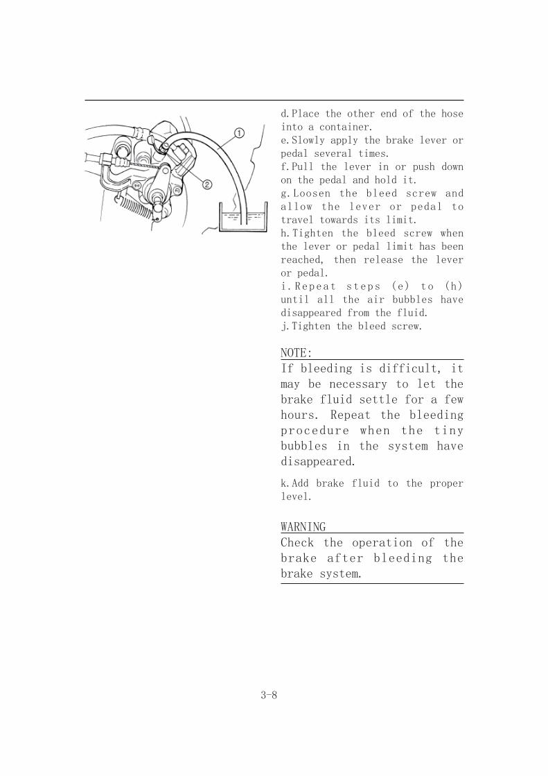
3-8
d.Place the other end of the hose into a container.e.Slowly apply the brake lever or pedal several times.f.Pull the lever in or push down on the pedal and hold it.g.Loosen the bleed screw and allow the lever or pedal to travel towards its limit.h.Tighten the bleed screw when the lever or pedal limit has been reached, then release the lever or pedal.i.Repeat steps (e) to (h) until all the air bubbles have disappeared from the fluid.j.Tighten the bleed screw.
NOTE:If bleeding is difficult, it may be necessary to let the brake fluid settle for a few hours. Repeat the bleeding procedure when the tiny bubbles in the system have disappeared.
k.Add brake fluid to the proper level.
WARNINGCheck the operation of the brake after bleeding the brake system.
3-9
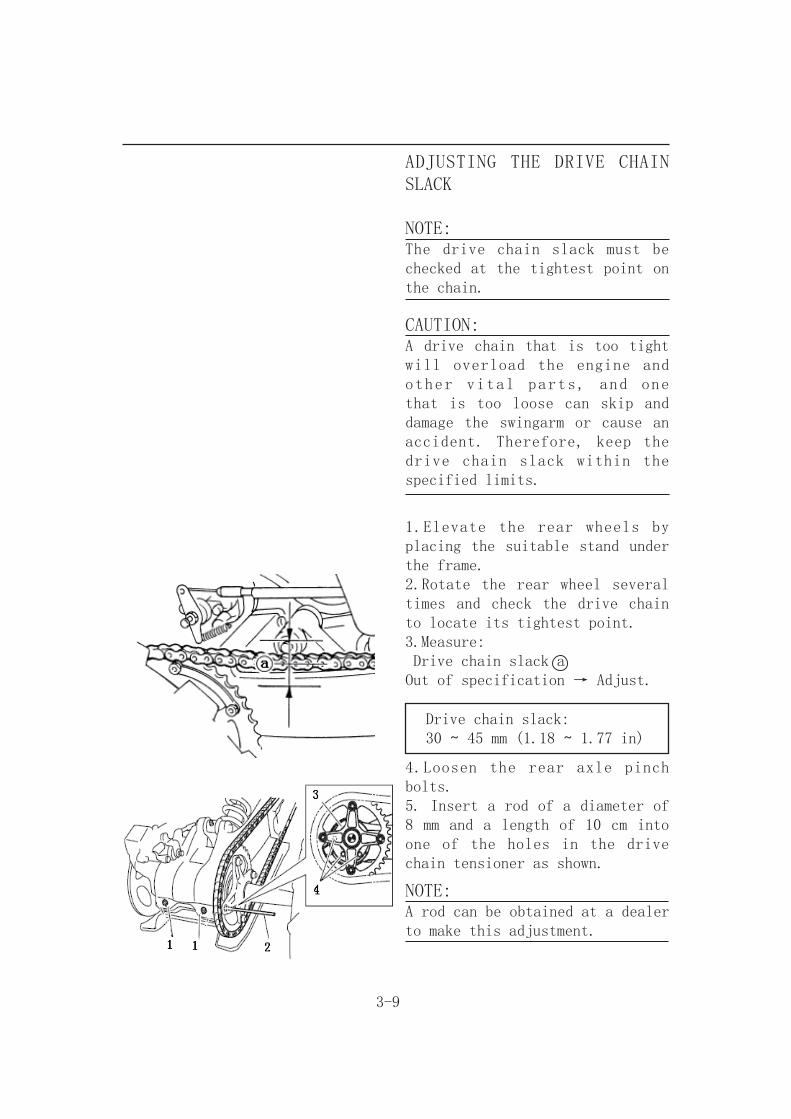
ADJUSTING THE DRIVE CHAIN SLACK
NOTE:The drive chain slack must be checked at the tightest point on the chain.
CAUTION:A drive chain that is too tight will overload the engine and other vital parts, and one that is too loose can skip and damage the swingarm or cause an accident. Therefore, keep the drive chain slack within the specified limits.
1.Elevate the rear wheels by placing the suitable stand under the frame.2.Rotate the rear wheel several times and check the drive chain to locate its tightest point.3.Measure: Drive chain slack aOut of specification → Adjust.
Drive chain slack: 30 ~ 45 mm (1.18 ~ 1.77 in)
4.Loosen the rear axle pinch bolts.5. Insert a rod of a diameter of 8 mm and a length of 10 cm into one of the holes in the drive chain tensioner as shown.
NOTE:A rod can be obtained at a dealer to make this adjustment.

3-10
1. Rear wheel axle pinch bolt2. Rod3. Drive chain tensioner4. Hole
6. Shift the transmission into neutral.7. To tighten the drive chain, push the ATV backward.To loosen the drive chain, push the ATV forward.
CAUTION:Improper drive chain slack will overload the engine as well as other vital parts of the ATV andcan lead to drive chain slippage or breakage.To prevent this from occurring, keep the drive chain slack within the specified limits.
8. Pull the rod out, and then tighten the rear axlepinch bolts to the specified torque.
Tightening torque:Rear axle pinch bolt:42 Nm (4.2 m·kgf, 30.4ft·lbf)
If the chain slack cannot be adjusted, replace the sprockets and drive chain as a set.The chain should be cleaned and lubricated after every use of the machine.
3-11
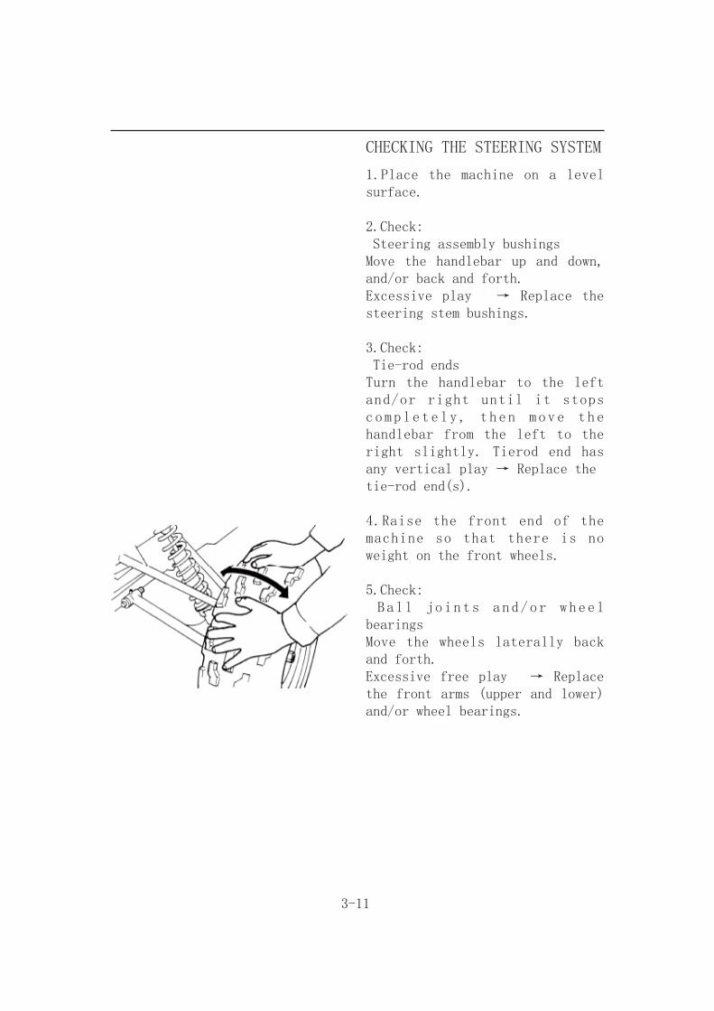
CHECKING THE STEERING SYSTEM
1.Place the machine on a level surface.
2.Check: Steering assembly bushingsMove the handlebar up and down, and/or back and forth.Excessive play → Replace the steering stem bushings.
3.Check: Tie-rod endsTurn the handlebar to the left and/or right until it stops completely, then move the handlebar from the left to the right slightly. Tierod end has any vertical play → Replace thetie-rod end(s).
4.Raise the front end of the machine so that there is no weight on the front wheels.
5.Check: Ball joints and/or wheel bearingsMove the wheels laterally back and forth.Excessive free play → Replace the front arms (upper and lower) and/or wheel bearings.

3-12
ADJUSTING THE TOE-IN
1.Place the machine on a level surface.2.Measure: Toe-inOut of specification → Adjust.
Toe-in:0 ~ 10 mm (0 ~ 0.39 in)
Toe-in measurement steps:NOTE:Before measuring the toe-in, make sure that the tire pressure is correct.
Mark both front tire tread centers.Raise the front end of the machine so that there is no weight on the front tires.Face the handlebar straight ahead.Measure the width A between the marks.Rotate the front tires 180°until the marks are exactly opposite one another.Measure the width B between the marks.Calculate the toe-in using the formula given below.
If the toe-in is incorrect, adjust it.
C Forward

3-13
3.Adjust: Toe-in
WARNING Be sure that both tie-rods are turned the same amount. If not, the machine will drift right or left even though the handlebar ispositioned straight. This may lead to mishandling and an accident. After setting the toe-in to specification, run the machine slowly for some distance with both hands lightly holding the handlebar and check that the handlebar responds correctly. If not, turn either the right or left tierod within the toe-in specification.
Adjustment steps:Mark both tie-rods ends.This reference point will be needed during adjustment.Loosen the locknuts (tie-rod end) ① of both tie-rods.The same number of turns should be given to both the right and left tie-rods ② until the specified toe-in is obtained. This is to keep the length of the rods the same.Tighten the rod end locknuts of both tie rods.
Locknut (rod end):15 Nm (1.5 m • kg, 11 ft • lb)
NOTE:Adjust the rod ends so that A and B are equal.

3-14
ADJUSTING THE FRONT SHOCK ABSORBER
WARNINGAlways adjust both front shock absorber spring preload to the same setting. Uneven adjustment can cause poor handling and loss of stability.
1.Adjust: Spring preloadTurn the adjuster ① in direction a or b .
Direction a
Direction b
Spring preload i s i n c r e a s e d (suspension is harder).
Spring preload i s d e c r e a s e d (suspension is softer).
Standard position: 3Minimum position: 1Maximum position: 5

3-15
ADJUSTING THE REAR SHOCKABSORBER
The spring preload can be adjusted to suit the rider’s weight and the riding conditions.
Adjustment steps:Elevate the rear wheels by placing a suitable stand under the frame.Turn the adjusting ring in direction (a) to increase the spring preload and thereby harden the suspension, and in direction (b) to decrease the spring preload and thereby soften the suspension.
NOTE:A special wrench can be obtained a t a d e a l e r t o m a k e t h i s adjustment.
1. Spring preload adjusting ring2. Position indicator
1. Special wrench
Spring preload setting:Minimum (soft): AMaximum (hard): E

3-16
CHECKING THE TIRE
WARNINGThis model is equipped with low pressure tires. It is important that they be inflated correctly and maintained at the proper pressures.
TIRE CHARACTERISTICS
Front
Rear
AT22×7-10
AT22×10-10
TIRE PRESSURE1)Recommended tire pressureFront 27.5 kPa (0.275 kg/cm2, 4.0 psi)Rear 27.5 kPa (0.275 kg/cm2, 4.0 psi)2)Tire pressure below the minimum specification could cause the tire to dislodge from the rim under severe riding conditions.The following are minimums:Front 24.5 kPa (0.245 kg/cm2, 3.5 psi)Rear 24.5 kPa (0.245 kg/cm2, 3.5 psi)3)Use no more thanFront 250 kPa (2.5 kg/cm2, 36 psi)Rear 250 kPa (2.5 kg/cm2, 36 psi)when seating the tire beads. Higher pressures may cause the tire to burst.Inflate the tires slowly and carefully.Fast inflation could cause the tire to burst.
3-17
MAXIMUM LOADING LIMIT1)Vehicle load limit (total weight of cargo,rider and accessories, and tongueweight): 150 kg
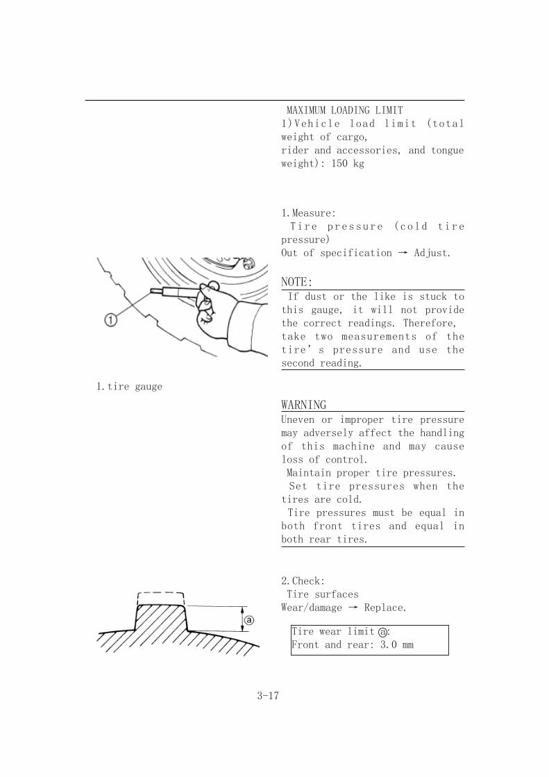
1.Measure: Tire pressure (cold tire pressure)Out of specification → Adjust.
NOTE: If dust or the like is stuck to this gauge, it will not provide the correct readings. Therefore,take two measurements of the tire’s pressure and use the second reading.
1.tire gauge
WARNINGUneven or improper tire pressure may adversely affect the handling of this machine and may cause loss of control. Maintain proper tire pressures. Set tire pressures when the tires are cold. Tire pressures must be equal in both front tires and equal in both rear tires.
2.Check: Tire surfacesWear/damage → Replace.
Tire wear limit a:Front and rear: 3.0 mm
3-18
WARNINGIt is dangerous to ride with a worn-out tire. When tire wear is out of specification, replace the tire immediately.
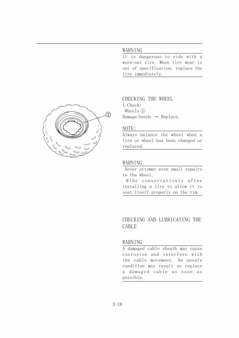
CHECKING THE WHEEL1.Check: Wheels ①Damage/bends → Replace.
NOTE:Always balance the wheel when a tire or wheel has been changed or replaced.
WARNING Never attempt even small repairs to the wheel. Ride conservatively after installing a tire to allow it to seat itself properly on the rim.
CHECKING AND LUBRICATING THECABLE
WARNINGA damaged cable sheath may cause corrosion and interfere with the cable movement. An unsafe condition may result so replace a damaged cable as soon as possible.

3-19
1.Check: Cable sheathDamage → Replace.2.Check: Cable operationUnsmooth operation → Lubricate or replace.
NOTE:Hold the cable end up and apply several drops of lubricant to the cable.
3.Apply: Lithium soap base grease(onto end of the cable)
LUBRICATING THE LEVERS AND PEDAL
1.Lubricate the pivoting parts.
Recommended lubricant: Lithium soap base grease

3-20
ELECTRICAL
CHECKING THE BATTERY
NOTE:Since the MF battery is a sealed type battery, it is not possible to measure the specific gravity of the electrolyte in order to check the charge state of the battery. Therefore the charge ofthe battery has to be checked by measuring the voltage at the battery terminals.
CAUTION:CHARGING METHOD This is a sealed type battery. Never remove the sealing caps. If the sealing caps have been removed, the balance will not be maintained and battery performance will deteriorate. Charging time, charging current and charging voltage for the MF battery are different from those of general type batteries.The MF battery should be charged as explained in “CHARGING METHOD”. If the battery is overcharged, the electrolyte level will drop considerably. Therefore, take special care when charging the battery.

3-21
WARNINGBattery electrolyte is dangerous; it contains sulfuric acid which is poisonous and highly caustic.Always follow these preventive measures: Avoid bodily contact with electrolyte as it can cause severe burns or permanent eye injury. Wear protective eye gear when handling or working near batteries.
Antidote (EXTERNAL): SKIN - Wash with water. EYES - Flush with water for 15 minutes and get immediate medical attention.Antidote (INTERNAL): Drink large quantities of water or milk followed with milk of magnesia, beaten egg or vegetable oil. Get immediate medical attention.
Batteries generate explosive hydrogen gas.Always follow these preventive measures: Charge batteries in a well-ventilated area. Keep batteries away from fire, sparks or open flames (e.g., w e l d i n g e q u i p m e n t , l i g h t e d cigarettes, etc.). DO NOT SMOKE when charging or handling batteries.
K E E P B A T T E R I E S A N D ELECTROLYTE OUT OF REACH OF CHILDREN.
3-22
1.Remove: Seat Battery holding bracket2.Disconnect: Battery leads
CAUTION:First disconnect the negative lead,then disconnect the positive lead .
3.Remove: Battery4.Check: Battery condition
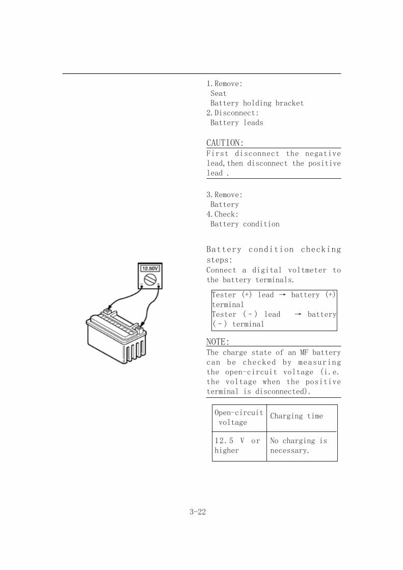
Battery condition checking steps:Connect a digital voltmeter to the battery terminals.
Tester (+) lead → battery (+) terminalTester (–) lead → battery (–) terminal
NOTE:The charge state of an MF battery can be checked by measuring the open-circuit voltage (i.e. the voltage when the positive terminal is disconnected).
Open-circuit voltage
Charging time
12.5 V or higher
No charging isnecessary.
3-23
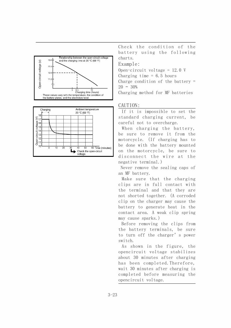
Check the condition of the battery using the following charts.
Example:Open-circuit voltage = 12.0 VCharging time = 6.5 hoursCharge condition of the battery = 20 ~ 30%Charging method for MF batteries
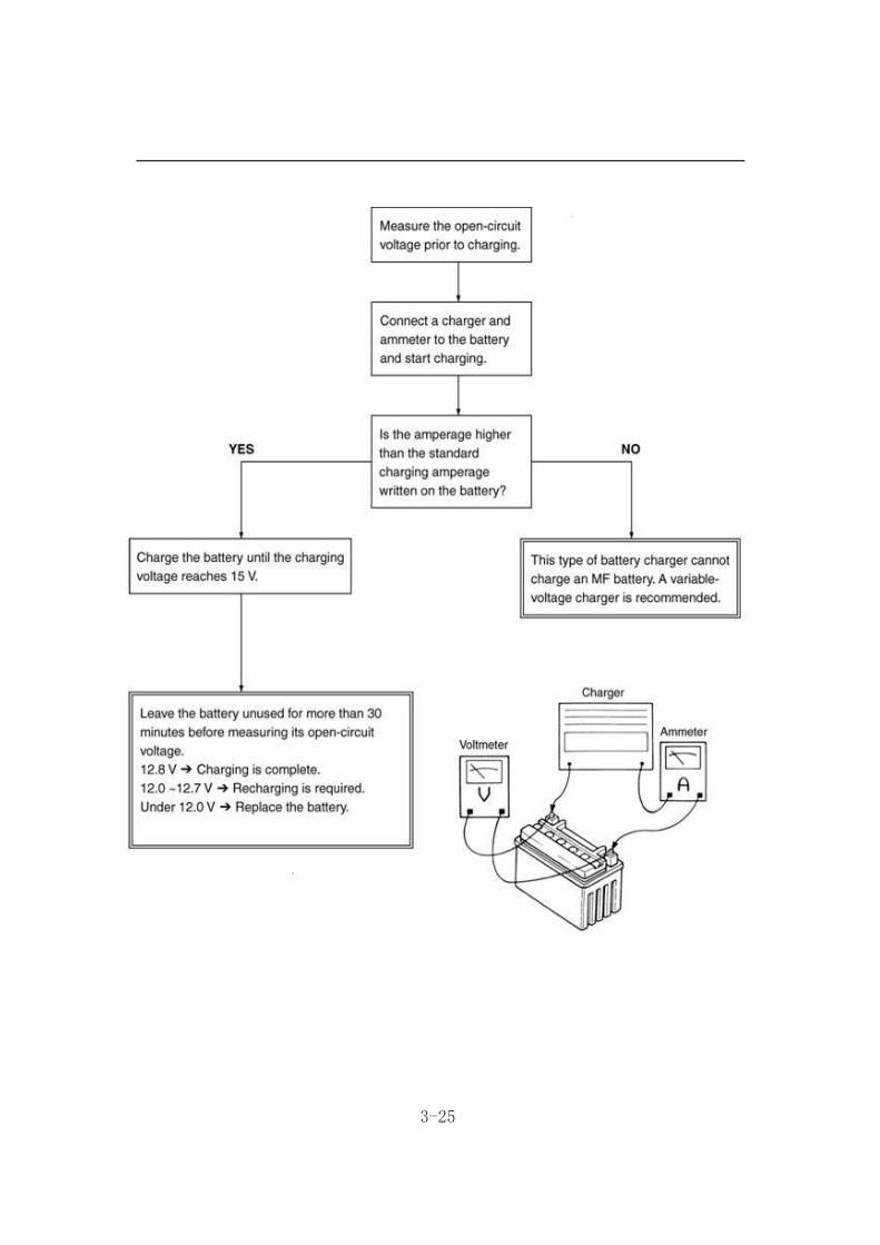
CAUTION: If it is impossible to set the standard charging current, be careful not to overcharge. When charging the battery, be sure to remove it from the motorcycle. (If charging has to be done with the battery mounted on the motorcycle, be sure to disconnect the wire at the negative terminal.) Never remove the sealing caps of an MF battery. Make sure that the charging clips are in full contact with the terminal and that they are not shorted together. (A corroded clip on the charger may cause the battery to generate heat in the contact area. A weak clip spring may cause sparks.) Before removing the clips from the battery terminals, be sure to turn off the charger’s power switch. As shown in the figure, the opencircuit voltage stabilizes about 30 minutes after charging has been completed.Therefore, wait 30 minutes after charging is completed before measuring the opencircuit voltage.
3-24
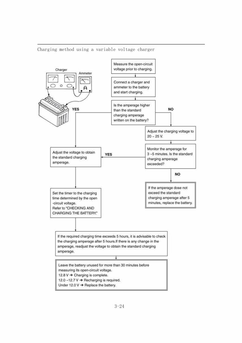
Charging method using a variable voltage charger
3-25
3-26
5.Check: Battery terminalsDirty → Clean with a wire brush.Poor connection → Correct.
NOTE:After cleaning the terminals, apply a light coat of grease.
6.Install: Battery
7.Connect: Battery leads
CAUTION:First,connect the positive lead,then connect the negative lead.
8.Install: Battery holding bracket Seat
CHECKING THE FUSE
CAUTION:Always turn off the main switch when checking or replacing a fuse. Otherwise, a short circuit may occur.
1.Remove: Seat
2.Check: Fuse
3-27
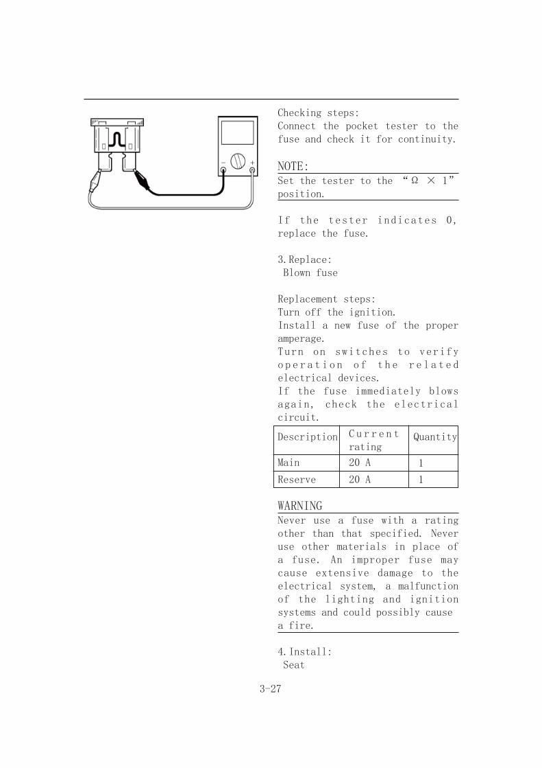
Checking steps:Connect the pocket tester to the fuse and check it for continuity.
NOTE:Set the tester to the “Ω × 1” position.
If the tester indicates 0, replace the fuse.
3.Replace: Blown fuse
Replacement steps:Turn off the ignition.Install a new fuse of the proper amperage.Turn on switches to verify o p e r a t i o n o f t h e r e l a t e d electrical devices.If the fuse immediately blows again, check the electrical circuit.
WARNINGNever use a fuse with a rating other than that specified. Never use other materials in place of a fuse. An improper fuse may cause extensive damage to the electrical system, a malfunction of the lighting and ignition systems and could possibly causea fire.
4.Install: Seat
Description C u r r e n t rating
Quantity
Main
Reserve
20 A
20 A
1
1
4-1
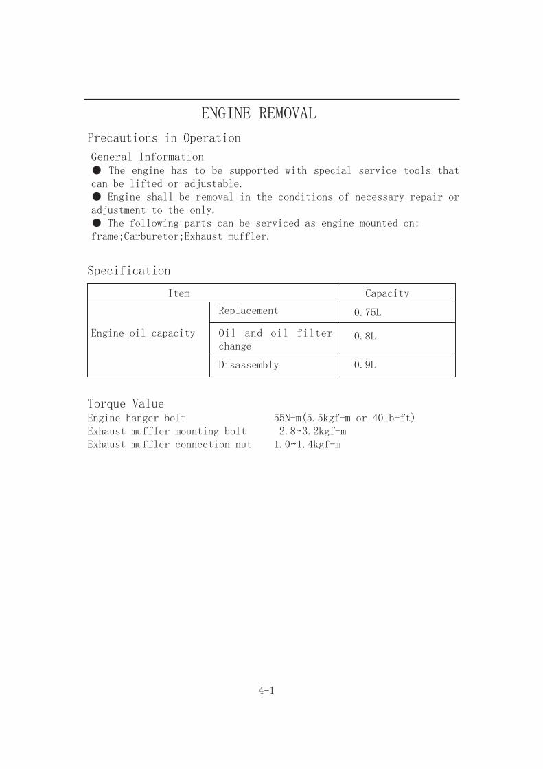
ENGINE REMOVAL
Precautions in Operation
General Information● The engine has to be supported with special service tools that can be lifted or adjustable.● Engine shall be removal in the conditions of necessary repair or adjustment to the only.● The following parts can be serviced as engine mounted on:frame;Carburetor;Exhaust muffler.
Specification
Item Capacity
Engine oil capacity
Replacement
Oil and oil filter change
Disassembly
Torque ValueEngine hanger bolt 55N-m(5.5kgf-m or 40lb-ft)Exhaust muffler mounting bolt 2.8~3.2kgf-mExhaust muffler connection nut 1.0~1.4kgf-m
0.75L
0.8L
0.9L
4-2
Engine Removal
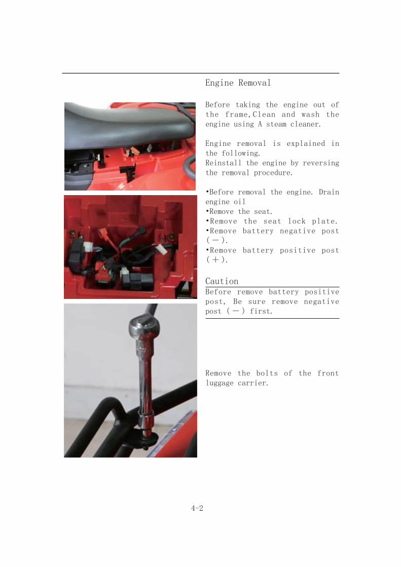
Before taking the engine out of the frame,Clean and wash the engine using A steam cleaner.
Engine removal is explained in the following.Reinstall the engine by reversing the removal procedure.
•Before removal the engine. Drain engine oil•Remove the seat. •Remove the seat lock plate. •Remove battery negative post ( - ). •Remove battery positive post ( + ).
CautionBefore remove battery positive post, Be sure remove negative post ( - ) first.
Remove the bolts of the front luggage carrier.

4-3
Remove the front luggage carrier.
Remove the bolts of the rear luggage carrier.
Remove the rear luggage carrier.
Remove the front fender side cover. (L and R)

4-4
Remove the footplate. (L and R)
Remove the bolts of the rear light decorated board.
Remove the decorated board.(L and R)
Remove the rear fender.
4-5
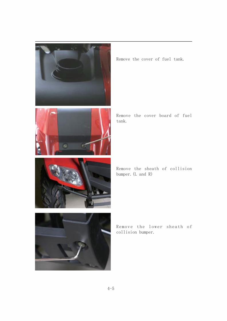
Remove the cover of fuel tank.
Remove the cover board of fuel tank.
Remove the sheath of collision bumper.(L and R)
Remove the lower sheath of collision bumper.

4-6
Remove the collision bumper.
Remove the cover of ignition switch.
Remove the handle.
Remove the front fender.

4-7
Remove the air intake pipe of engine.Remove the air export pipe of engine.
Remove the fuel hose and vacuum hose.
Remove the fuel tank.
Remove the air cleaner.
Remove the carburetor.
4-8
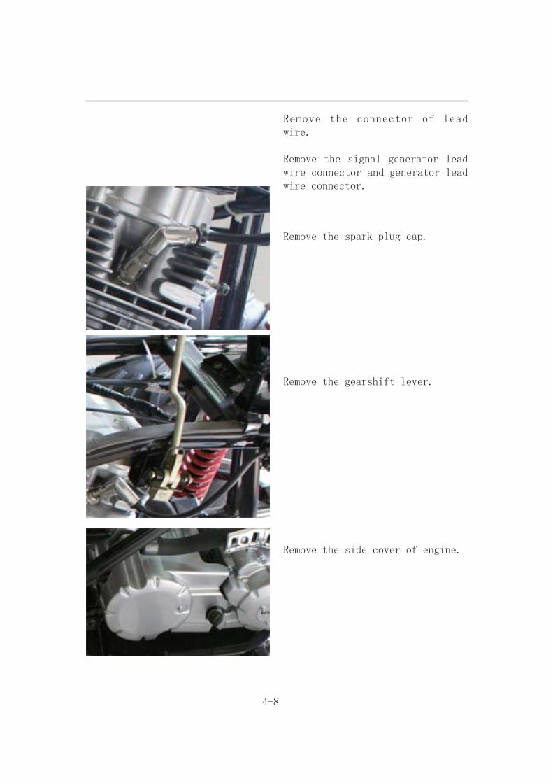
Remove the connector of lead wire.
Remove the signal generator lead wire connector and generator lead wire connector.
Remove the spark plug cap.
Remove the gearshift lever.
Remove the side cover of engine.
4-9
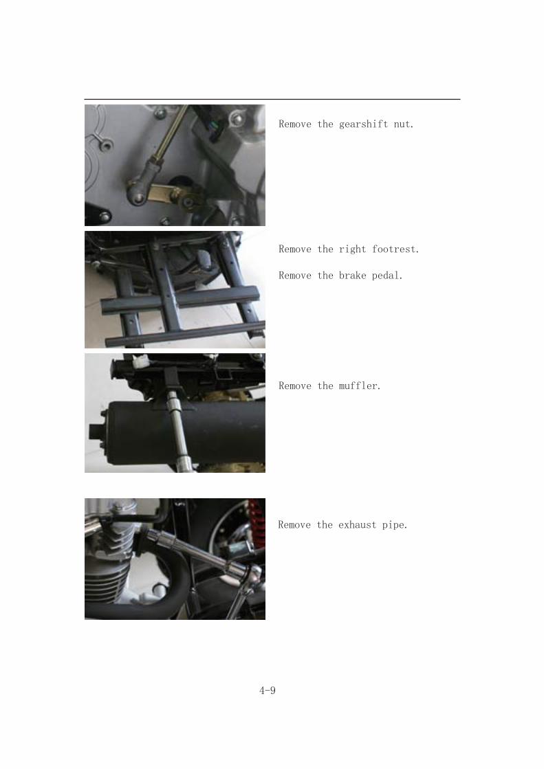
Remove the gearshift nut.
Remove the right footrest.
Remove the brake pedal.
Remove the muffler.
Remove the exhaust pipe.

4-10
Remove the engine mounting bolts and nuts.
Remove the engine from the right side.
Engine installation
Remove the engine in the reverse order of engine removal.
CautionThe engine mounting nuts are self-locking.Once the nut was been removed it is no longer of any use. Be sure to use new nuts for every time engine installation and tighten them。

5-1
FRONT BRAKE & FRONT WHEELMaintenance
Operational precautions
CautionInhaling asbestos may cause disorders of respiration system or cancer, therefore, never use air hose or dry brush to clean brake parts. Use vacuum cleaner or other authorized tool instead.
● The brake caliper can be removed without removing the hydraulic system.● After the hydraulic system is removed, the brake system is felt to be too soft, bleed the hydraulic system.● While refilling brake fluid, care should be taken not to let the foreign material entering into the brake system.● Do not spill brake fluid on the painted surfaces, plastic or rubber parts to avoid damage.● Check the operation of the brake system before riding.
Specifications
Item Standard (mm) Limit (mm)
The thickness of front and rear brake disk
3.500 2.000
Torque values
Brake hose bolts 3.50kgf-m Bolt for brake caliper 3.25kgf-m Bolts for the brake disk 4.25kgf-m Brake lever nut 1.00kgf-m Air-bleed valve 0.50kgf-m Front wheel nut 2.40kgf-m Front axle castle nut 5.00kgf-m

5-2
Trouble Diagnosis
Soft brake lever
1.Air inside the hydraulic system 2.Hydraulic system leaking3.Worn master piston4.Worn brake pad5.Poor brake caliper6.Worn brake lining/disk7.Low brake fluid8.Blocked brake hose9.Warp/bent brake disk10.Bent brake lever
Hard operation of brake lever
1.Blocked brake system2.Poor brake caliper 3.Blocked brake pipe4.Seized/worn master cylinder piston5.Bent brake lever
Uneven brake
1.Dirty brake lining/disk2.Poor wheel alignment3.Clogged brake hose4.Deformed or warped brake disk5.Restricted brake hose and fittings
Tight brake
1.Dirty brake lining/disk2.Poor wheel alignment3.Deformed or warped brake disk
Brake noise
1.Dirty lining 2.Deformed brake disk 3.Poor brake caliper installation 4.Imbalance brake disk or wheel
Hard steering
1.Faulty tire 2.Insufficient tire pressure
Front wheel wobbling
1.Faulty tire2.Worn front brake drum bearing3.Bent rim 4.Axle nut not tightened properly
Steers to one side
1.Bent tie rods2.Wheel installed incorrectly3.Unequal tire pressure4.Incorrect wheel alignment

5-3
Front Wheel
Removal
Raise the front wheels off the ground by placing a jack or other support under the frame.
Remove the front wheel nuts, and then remove front wheels.
Installation
Install the front wheel and tighten the nuts.
Torque: 5.0kgf-m
Front Wheel Hub
Removal
Remove front brake caliper (2 bolts).
5-4
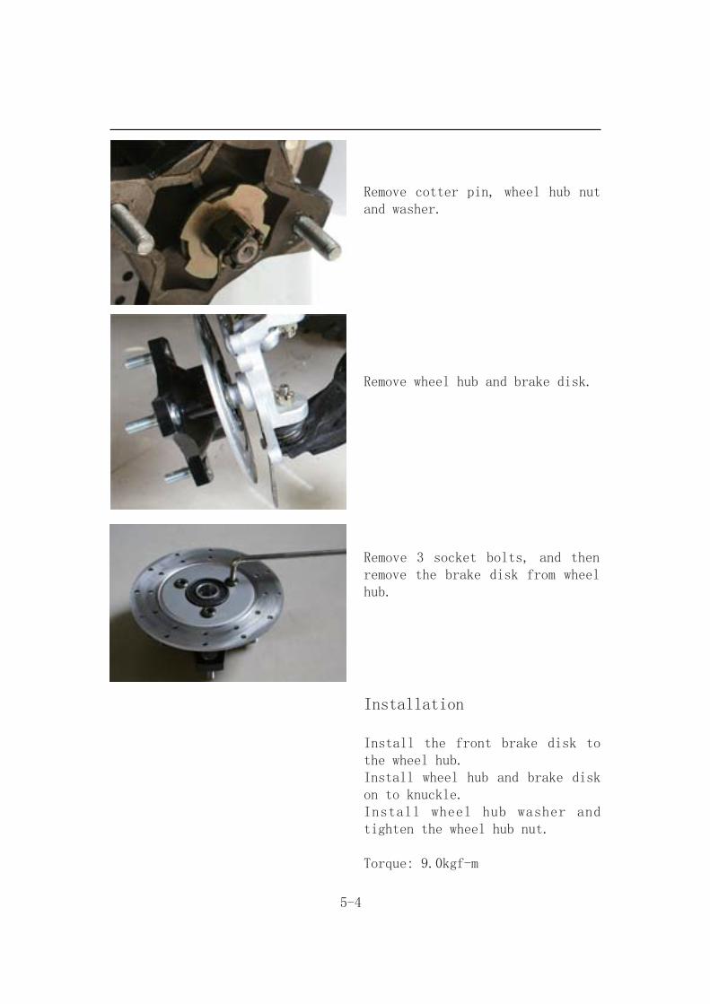
Remove cotter pin, wheel hub nut and washer.
Remove wheel hub and brake disk.
Remove 3 socket bolts, and then remove the brake disk from wheel hub.
Installation
Install the front brake disk to the wheel hub. Install wheel hub and brake disk on to knuckle. Install wheel hub washer and tighten the wheel hub nut.
Torque: 9.0kgf-m
5-5
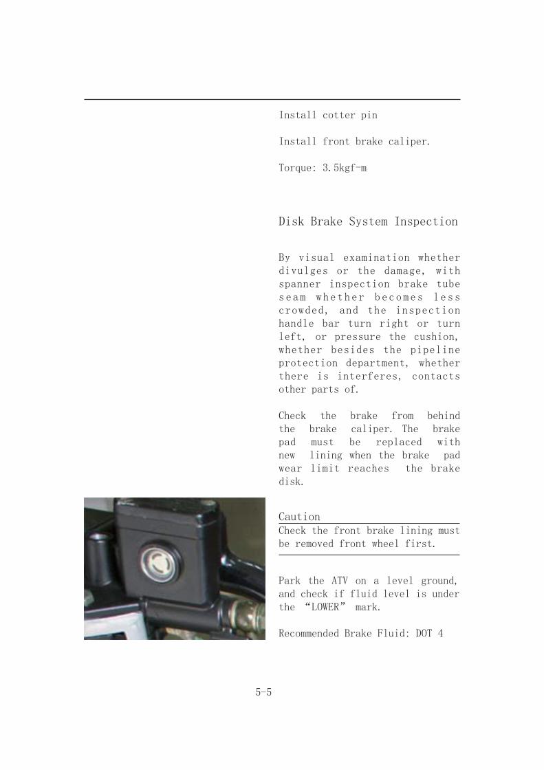
Install cotter pin
Install front brake caliper.
Torque: 3.5kgf-m
Disk Brake System Inspection
By visual examination whether divulges or the damage, with spanner inspection brake tube seam whether becomes less crowded, and the inspection handle bar turn right or turn left, or pressure the cushion, whether besides the pipeline protection department, whether there is interferes, contacts other parts of.
Check the brake from behind the brake caliper. The brake pad must be replaced with new lining when the brake pad wear limit reaches the brake disk.
CautionCheck the front brake lining must be removed front wheel first.
Park the ATV on a level ground, and check if fluid level is under the “LOWER” mark.
Recommended Brake Fluid: DOT 4

5-6
Adding Brake Fluid
Before the brake fluid reservoir is removed, turn the handle so that the brake fluid reservoir becomes horizontal, and then remove the brake fluid reservoir.
When maintenance brake system, will be supposed to paint the surface or the rubber parts catches up by the rags.
CautionSupplement brake fluid please do not surpass the upper limit, spilled brake fluid on painted surfaces, plastic or rubber components may result in their damages.
Remove the master cylinder cap and diaphragm.Increases the high quality brake fluid, uses by all means must with the trade mark brake fluid joins in the master cylinder.Clean the dirty brake disk.
Caution● The dirty brake lining or disk will reduce the brake performance.● To mixed non-compatible brake fluid will reduce brake performance.● Fo r e i g n m a t e r i a l s w i l l block the system causing brake performance to be reduced or totally lost.

5-7
Brake fluid replacement
WARNINGBleed the brake system if: T h e s y s t e m h a s b e e n disassembled. A brake hose or brake pipe have been loosened or removed. The brake fluid has been very low. The brake operation has been faulty.A loss of braking performance may occur if the brake system is not properly bled.
Air bleeding steps:
a. Add the proper brake fluid to the reservoir.
b. Install the diaphragm. Be careful not to spill any fluid or allow the reservoir to overflow.
c. Connect the clear plastic hose ① tightly to the caliper bleed screw ② .
d. Place the other end of the hose into a container.
e. Slowly apply the brake lever or pedal several times.
f. Pull the lever in or push down on the pedal and hold it.
g. Loosen the bleed screw and allow the lever or pedal to travel towards its limit.
5-8
Front Brake Caliper
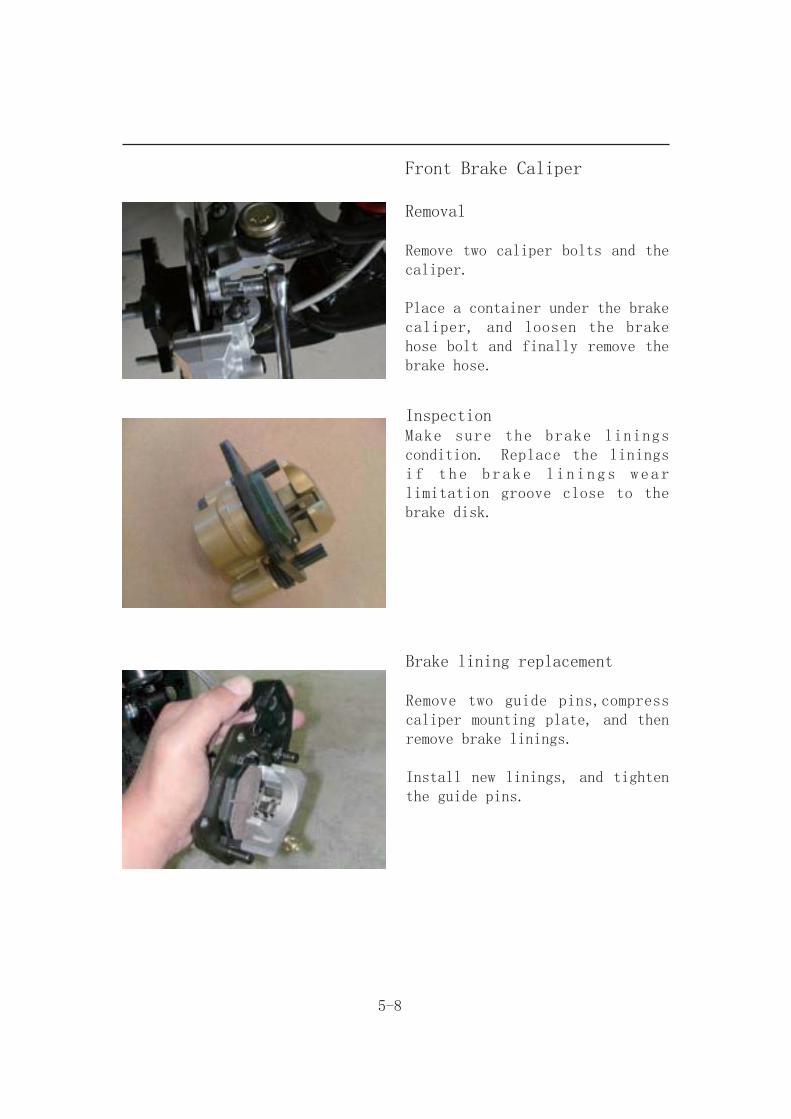
Removal
Remove two caliper bolts and the caliper.
Place a container under the brake caliper, and loosen the brake hose bolt and finally remove the brake hose.
InspectionMake sure the brake linings condition. Replace the linings if the brake linings wear limitation groove close to the brake disk.
Brake lining replacement
Remove two guide pins,compress caliper mounting plate, and then remove brake linings.
Install new linings, and tighten the guide pins.

5-9
Installation
Install the brake caliper and tighten the attaching bolts securely.
Torque: 3.25kgf-m
Caution● Use M8 x 18 mm flange bolt only.● Long bolt will impair the operation of brake disk.
Use two seal washers and hose bolts to lock the hose and brake caliper in place.
Torque: 3.5kgf-m
Refill up the brake fluid to the reservoir and make necessary air bleeding.
5-10
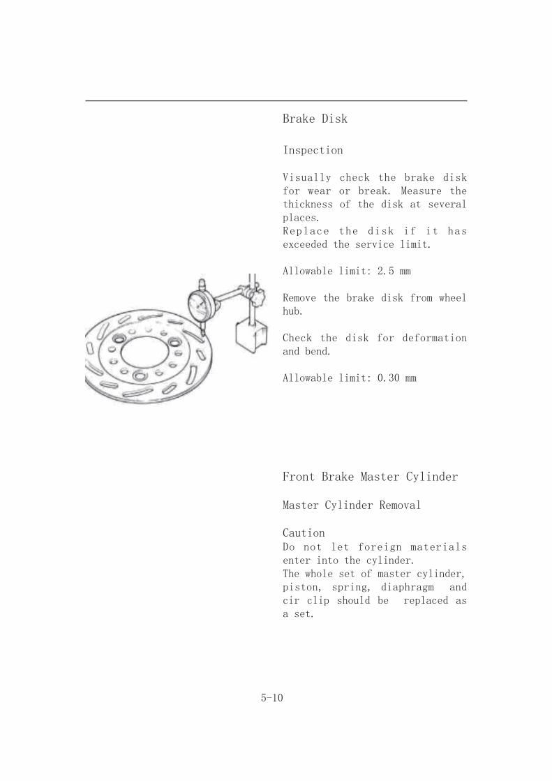
Brake Disk
Inspection
Visually check the brake disk for wear or break. Measure the thickness of the disk at several places. Replace the disk if it has exceeded the service limit.
Allowable limit: 2.5 mm
Remove the brake disk from wheel hub.
Check the disk for deformation and bend.
Allowable limit: 0.30 mm
Front Brake Master Cylinder
Master Cylinder Removal
CautionDo not let foreign materials enter into the cylinder.The whole set of master cylinder, piston, spring, diaphragm and cir clip should be replaced as a set.
5-11
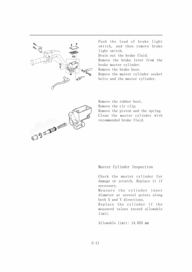
Push the lead of brake light switch, and then remove brake light switch.Drain out the brake fluid.Remove the brake lever from the brake master cylinder.Remove the brake hose.Remove the master cylinder socket bolts and the master cylinder.
Remove the rubber boot.Remove the cir clip.Remove the piston and the spring.Clean the master cylinder with recommended brake fluid.
Master Cylinder Inspection
Check the master cylinder for damage or scratch. Replace it if necessary.Measure the cylinder inner diameter at several points along both X and Y directions.Replace the cylinder if the measured values exceed allowable limit.
Allowable limit: 14.055 mm
5-12
Measure the outer diameter of the piston. Replace the piston if its measured value exceeds allowable limit.
Allowable limit: 13.945 mm
Master Cylinder Assembly
Caution● It is necessary to replace the whole set comprising piston, spring, piston cup, and cir clip.● Make sure there is no dust on all components before assembling.
Apply clean brake fluid to the piston cup, and then install the cup onto the piston.
Install the larger end of the spring onto the master cylinder.
The master cup’s cavity should be face inside of master cylinder when installing the master cup. Install the cir clip.
CautionNever install cup lip in the opposite direction.Make sure the cir clip is seated securely in the groove.
5-13
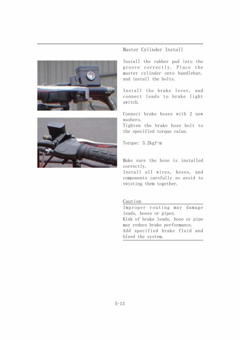
Master Cylinder Install
Install the rubber pad into the groove correctly. Place the master cylinder onto handlebar, and install the bolts.
Install the brake lever, and connect leads to brake light switch.
Connect brake hoses with 2 new washers.Tighten the brake hose bolt to the specified torque value.
Torque: 3.2kgf-m
Make sure the hose is installed correctly.Install all wires, hoses, and components carefully so avoid to twisting them together.
CautionImproper routing may damage leads, hoses or pipes.Kink of brake leads, hose or pipe may reduce brake performance.Add specified brake fluid and bleed the system.

6-1
REAR BRAKE & REAR WHEEL
Maintenance Description
Operational precautions
CautionInhaling asbestos may cause disorders of respiration system or cancer, therefore, never use air hose or dry brush to clean brake parts. Use vacuum cleaner or other authorized tool instead.
● The brake caliper can be removed without removing the hydraulic system.● After the hydraulic system is removed, the brake system is felt to be too soft, bleed the hydraulic system.● While refilling brake fluid, care should be taken not to let the foreign material entering into the brake system.● Do not spill brake fluid on the painted surfaces, plastic or rubber parts to avoid damage.● Check the operation of the brake system before riding.
Specifications
Item Standard (mm) Limit (mm)
The thickness of rear brake disk 4.0 2.5
Torque values
Brake hose bolt 3.50kgf-m Bolt for brake caliper 3.25kgf-m Bolts for the brake disk 4.25kgf-m Brake lever nut 1.00kgf-m Air-bleed valve 0.50kgf-m Rear wheel nut 2.40kgf-m
Rear axle castle nut 5.00kgf-m Rear axle holder bolt 9.20kgf-m Rear wheel axle nut 9.20kgf-m Rear cushion mounting bolt 4.6kgf-mSwing arm pivot bolt 9.2kgf-m

6-2
Trouble Diagnosis
Soft brake lever
1.Air inside the hydraulic system 2.Hydraulic system leaking3.Worn master piston4.Worn brake pad5.Poor brake caliper6.Worn brake lining/disk7.Low brake fluid8.Blocked brake hose9.Warp/bent brake disk10.Bent brake lever
Hard operation of brake lever
1.Blocked brake system2.Poor brake caliper 3.Blocked brake pipe4.Seized/worn master cylinder piston5.Bent brake lever
Uneven brake
1.Dirty brake lining/disk2.Poor wheel alignment3.Clogged brake hose4.Deformed or warped brake disk5.Restricted brake hose and fittings
Tight brake
1.Dirty brake lining/disk2.Poor wheel alignment3.Deformed or warped brake disk
Brake noise
1.Dirty lining 2.Deformed brake disk 3.Poor brake caliper installation 4.Imbalance brake disk or wheel
Vibration or Wobble
1. Axle is not tightened well2. Bent rim3. Axle bearings are worn4. Faulty tires5. Rear axle bearing holder is faulty
Soft Suspension
1. Weak shock absorber damper2. Weak shock absorber spring

Rear Wheel
6-3
Removal
Raise the rear wheels off the ground by placing a jack or other support under the frame.
Remove the rear wheel nuts, and then remove the rear wheels.
Installation
Install the rear wheel and tighten the nuts.
Torque: 2.4kgf-m
Rear Brake
Remove
Remove the brake caliper 2 nuts. and then remove the brake caliper。

6-4
Disk Brake System Inspection
Inspection
By visual examination whether divulges or the damage, with spanner inspection brake tube seam whether becomes less crowded, and the inspection handle bar turn right or turn left, or pressure the cushion, whether besides the pipeline protection department, whether there is interferes, contacts other parts of.
Check the brake from behind the brake caliper. The brake pad must be replaced with new lining when the brake pad wear limit reaches the brake disk
Park the ATV on a level ground, and check if fluid level is under the “LOWER” mark.
Recommended Brake Fluid: DOT 4
Caution● The vehicles inclined or just stop, the survey oil level could not be accurate, had to settle the 3~5 minute ● In order to prevent has the chemical change, please do not use counterfeiting or other unclear trade marks brake fluid.● Uses by all means must with the trade mark brake fluid, guarantees the ghost vehicle efficiency.

6-5
Rear Wheel Axle
Remove the rear wheel axle circlip by external circlip pliers.
Removal
Remove the bushing.
Remove the nut.
Remove the clip.

6-6
Remove the chain.
Remove the sprocket of final driven.
Remove the rear wheel axle circlip by external circlip pliers.Remove the left bushing.
Remove the nut.
6-7
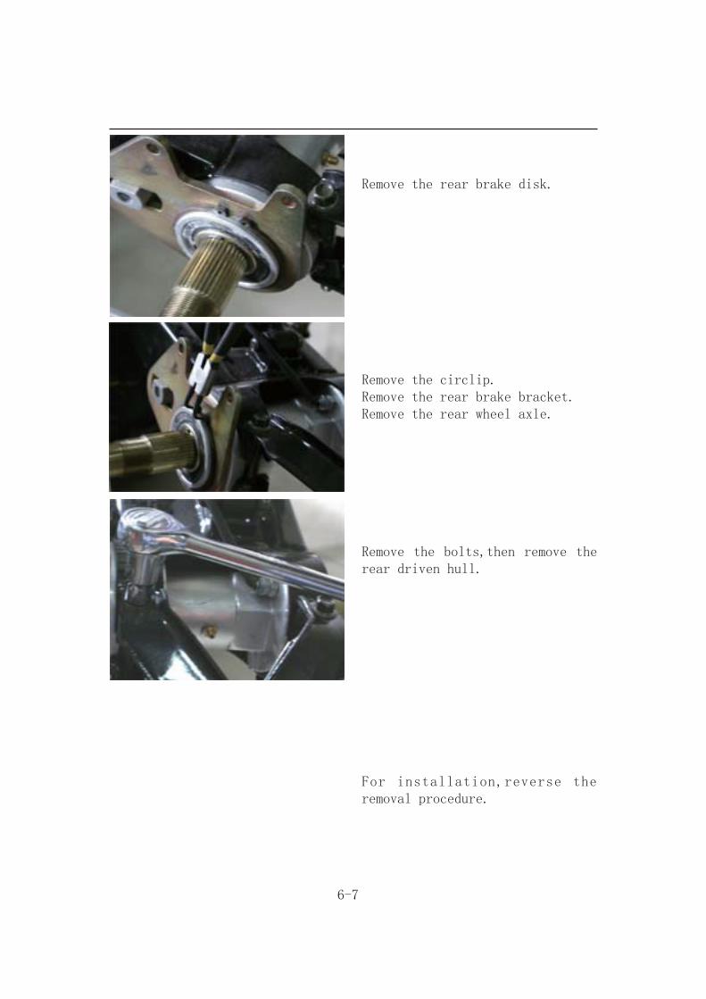
Remove the rear brake disk.
Remove the circlip.Remove the rear brake bracket.Remove the rear wheel axle.
Remove the bolts,then remove the rear driven hull.
For installation,reverse the removal procedure.

6-8
Adding Brake Fluid
Before the brake fluid reservoir is removed, turn the handle so that the brake fluid reservoir becomes horizontal, and then remove the brake fluid reservoir.
When maintenance brake system, will be supposed to paint the surface or the rubber parts catches up by the rags.
CautionSupplement brake fluid please do not surpass the upper limit, spilled brake fluid on painted surfaces, plastic or rubber components may result in their damages.
Remove the brake fluid cap and diaphragm. Increases the high quality brake fluid, uses by all means must with the trade mark brake fluid joins in the master cylinder.
Recommended: DOT 4
Clean the dirty brake disk.

Caution● The dirty brake lining or disk will reduce the brake performance.● To mixed non-compatible brake fluid will reduce brake performance.● Fo r e i g n m a t e r i a l s w i l l block the system causing brake performance to be reduced or totally lost.
6-9
Brake fluid replacement
Connect drain hose to air-bleed valve.
Open the drain valve on the caliper and operate the brake lever until the old brake fluid is entirely drained out.
Close the drain valve and add specified brake fluid into the brake master cylinder.
Recommended brake fluid: DOT 4

6-10
Connect one end of transparent hose to the drain valve, and put the other end into a container. Open the drain valve around 1/4 turns, and at the same time hold the brake lever until the there is no air bubble in the drain hose and also feeling resistance on the brake lever.
Close the drain valve when finishing the brake system refilling fluid procedure, and operate the brake lever to check whether air bubble is in brake system or not.
If brake is still soft, please bleed the system as described below:
1. Tightly hold the brake lever and open the drain valve around 1/4 turns, and then close the valve.2. Slowly release the brake lever, and wait for a few seconds until it reaches its top position.3. Repeat the steps 1 and 2 until there is no air bubble at the end of the hose.4. Tightly close the drain valve.5. Make sure the brake fluid is in the UPPER level of the master cylinder, and refill the fluid if necessary.6. Cover the cap.
6-11
Rear Brake Caliper
Removal
Remove two caliper bolts and the caliper.Place a container under the brake caliper, and loosen the brake hose bolt and finally remove the brake hose.
Installation
Install the brake caliper and tighten the attaching bolts securely.
Torque: 3.25kgf-m
Use two seal washers and hose bolts to lock the hose and brake caliper in place.
Torque: 3.5kgf-m
Refill up the brake fluid to the reservoir and make necessary air bleeding.
6-12
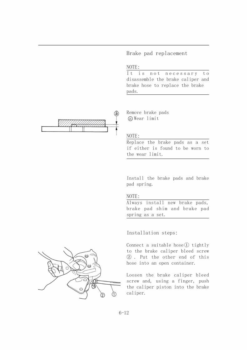
Brake pad replacement
NOTE:I t i s n o t n e c e s s a r y t o disassemble the brake caliper and brake hose to replace the brakepads.
Remove brake pads a Wear limit
NOTE:Replace the brake pads as a set if either is found to be worn to the wear limit.
Install the brake pads and brake pad spring.
NOTE:Always install new brake pads, brake pad shim and brake pad spring as a set.
Installation steps:
Connect a suitable hose① tightly to the brake caliper bleed screw ② . Put the other end of this hose into an open container.
Loosen the brake caliper bleed screw and, using a finger, push the caliper piston into the brake caliper.
6-13
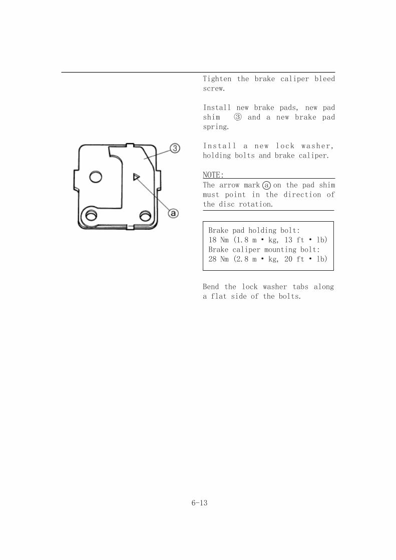
Tighten the brake caliper bleed screw.
Install new brake pads, new pad shim ③ and a new brake pad spring.
Install a new lock washer, holding bolts and brake caliper.
NOTE:The arrow mark a on the pad shim must point in the direction of the disc rotation.
Brake pad holding bolt:18 Nm (1.8 m • kg, 13 ft • lb)Brake caliper mounting bolt:28 Nm (2.8 m • kg, 20 ft • lb)
Bend the lock washer tabs along a flat side of the bolts.
6-14
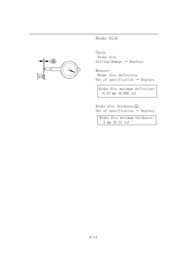
Brake Disk
Check: Brake discGalling/damage → Replace.
Measure: Brake disc deflectionOut of specification → Replace.
Brake disc maximum deflection: 0.15 mm (0.006 in)
Brake disc thickness aOut of specification → Replace.
Brake disc minimum thickness: 3 mm (0.12 in)

6-15
Rear Brake Master Cylinder
Removal
Remove the bolt,then remove the brake pedal.
Remove the two bolts.
Place a container under the brake caliper, and loosen the brake hose bolt and finally remove the brake hose.
Check
Brake master cylinderWear/scratches → Replace the brake master cylinder assembly.
Brake master cylinder bodyCracks/damage → Replace.
Brake fluid delivery passage(brake master cylinder body)B l o c k a g e → B l o w o u t w i t h compressed air.
Rear brake fluid reservoirCracks/damage → Replace.
6-16
Install
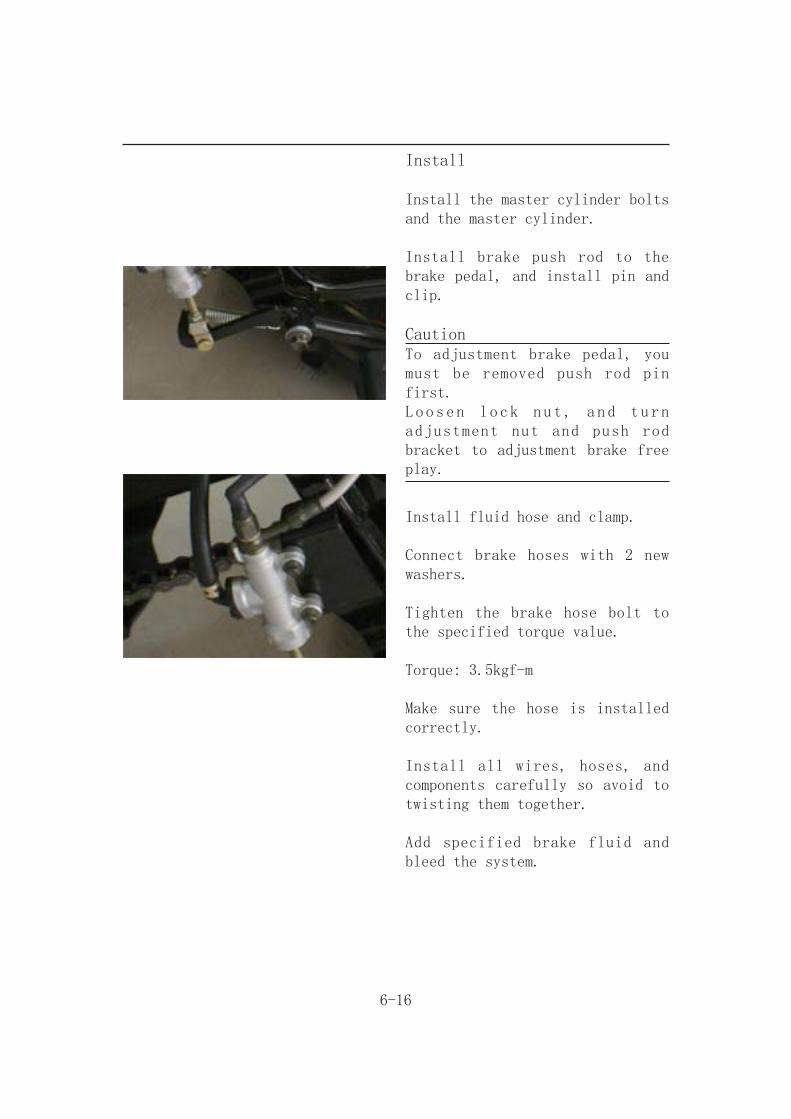
Install the master cylinder bolts and the master cylinder.
Install brake push rod to the brake pedal, and install pin and clip.
CautionTo adjustment brake pedal, you must be removed push rod pin first.Loosen lock nut, and turn adjustment nut and push rod bracket to adjustment brake free play.
Install fluid hose and clamp.
Connect brake hoses with 2 new washers.
Tighten the brake hose bolt to the specified torque value.
Torque: 3.5kgf-m
Make sure the hose is installed correctly.
Install all wires, hoses, and components carefully so avoid to twisting them together.
Add specified brake fluid and bleed the system.

7-1
STEERING SYSTEM
Handlebar
Removal
Remove the meter and meter cover.
Remove the brake master cylinder and throttle lever assembly.
Remove the park switch and handlebar switch.
Remove the meter cover bracket and handlebar holder.
Remove the handlebar.

7-2
Remove the handlebar.
NOTEBlow compressed air between the handlebar and handlebar grip, and gradually push the grip off the handlebar.
Check
Handlebar ①Bends/cracks/damage → Replace.
WARNINGDo not attempt to straighten a bent handlebar as this may dangerously weaken the handlebar.
Installation
For installation,reverse the removal procedure.
Installing the handlebar
Handlebar Handlebar holders Meter cover brackets
CAUTIONFirst tighten the bolts ① on the front side of the handlebar holder, and then tighten thebolts ② on the rear side.
7-3
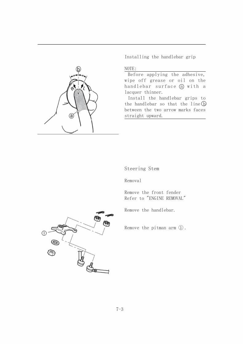
Installing the handlebar grip
NOTE: Before applying the adhesive, wipe off grease or oil on the handlebar surface a with a lacquer thinner. Install the handlebar grips to the handlebar so that the line b between the two arrow marks faces straight upward.
Steering Stem
Removal
Remove the front fenderRefer to "ENGINE REMOVAL"
Remove the handlebar.
Remove the pitman arm ① .
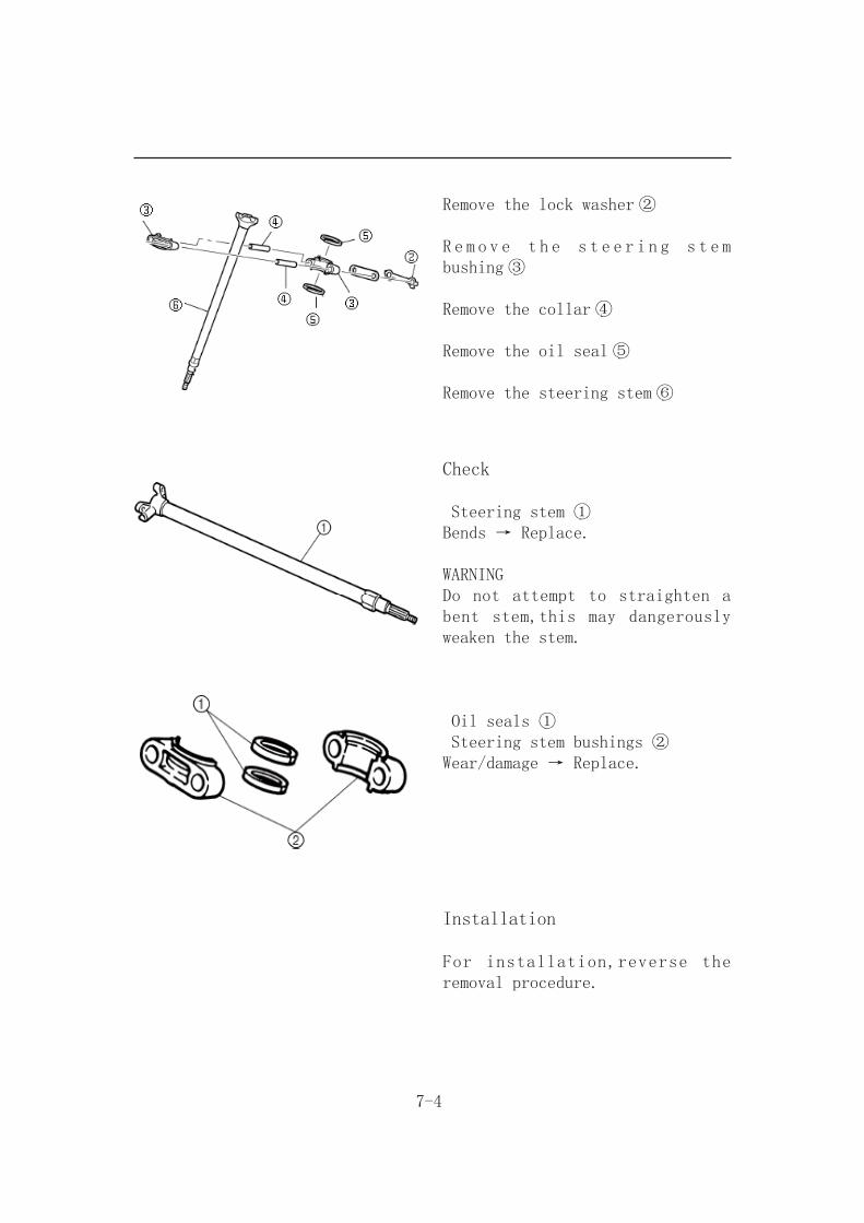
7-4
Remove the lock washer ②
R e m o v e t h e s t e e r i n g s t e m bushing ③
Remove the collar ④
Remove the oil seal ⑤
Remove the steering stem ⑥
Installation
For installation,reverse the removal procedure.
Check
Steering stem ①Bends → Replace.
WARNINGDo not attempt to straighten a bent stem,this may dangerously weaken the stem.
Oil seals ① Steering stem bushings ②Wear/damage → Replace.

7-5
Tie-rod and Steering Stem
Removal
Remove the front wheel and brake disc.
Remove the tie-rod ① .
Remove the pitman arm ② .
Remove the brake disc guard.
Remove the front arm(lower) ③ .
Remove the front arm(upper) ④ .
Remove the steering knuckle ⑤ .

7-6
Check
Check the tie-rod
Tie-rod free play and movementFree play → Replace the tie-rod end.Turns roughly → Replace the tie-rod end.
Bends/damage → Replace.
Checking the steering knuckle
Damage/pitting → Replace.
Installation
For installation,reverse the removal procedure.
Installing the tie-rod
NOTEThe tie-rod which must be installed on the out side has grooves ① .
8-1
ELECTRICAL SYSTEM
Maintenance Description
Operational precaution
● When remove the battery, the disconnection sequence of cable terminals shall be strictly observed.(First disconnect the negative cable terminal, next, the positive cable terminal.)● The model of the spark plug and the tightening torque. ● The ignition timing. ● Adjustment of headlight. ● Removal and installation of AC generator. ● The maintenance free battery requires no inspection of electrolyte level and refilling of distilled water.● To recharge the battery, remove the battery from rack without removing ventilation caps.● Unless in emergency, never rapid charge the battery.● The voltage must be checked with the voltmeter while charging the battery.● As C.D.I assembly does not require an ignition timing check. In case ignition timing is incorrect, check C.D.I and AC generator. Verify with an ignition timing light after replacement if necessary.
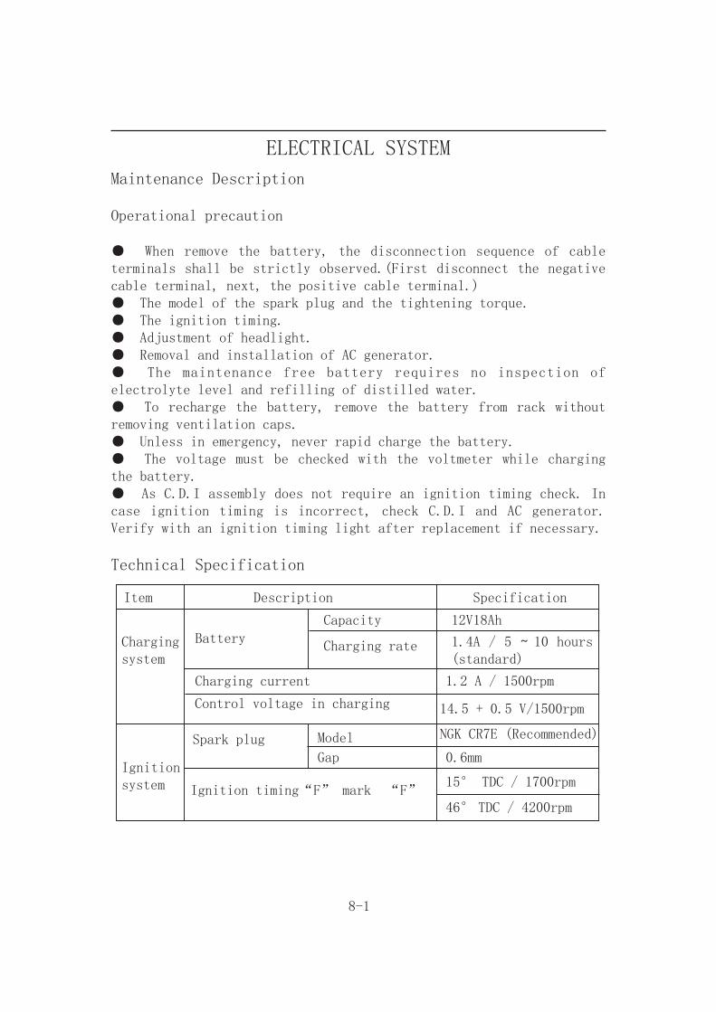
Technical Specification
Item Description Specification
Chargingsystem
Battery
Capacity
Charging rate
12V18Ah
1.4A / 5 ~ 10 hours (standard)
Charging current 1.2 A / 1500rpm
Control voltage in charging 14.5 + 0.5 V/1500rpm
Ignition system
Spark plug Model NGK CR7E (Recommended)
Gap 0.6mm
Ignition timing“F” mark “F”15° TDC / 1700rpm
46° TDC / 4200rpm

8-2
Trouble Diagnosis
No voltage● Battery discharged ● The cable disconnected● The fuse is blown● Improper operation of the main switch
Low voltage● The battery is not fully charged● Poor contact● Poor charging system● Poor voltage regulator
No spark produced by spark plug● The spark plug is out of work● The cable is poorly connected, open or short-circuited-Between AC.G. and C.D.I.● Poor connection between C.D.I. and ignition Coil-Poor connection between C.D.I. and the main switch.● Poor main switch● Poor C.D.I.● AC.G. is out of work
Intermittent power supply● The connector of the charging system becomes loose.● Poor connection of the battery cable.● Poor connection or short-circuit of the discharging system● Poor connection or short-circuit of the power generation system.
Engine does not crank smoothly● Primary winding circuit-Poor ignition coil-Poor connection of cable and connectors-Poor main switch● Secondary winding circuit-Poor ignition coil-Poor spark plug-Poor ignition coil cable-Current leakage in the spark plug● Incorrect ignition timing-Poor AC.G. -Improper installation of the pulse sensor-Poor C.D.I.
Starter motor does not work● The fuse is blown● The battery is not fully charge● Poor main switch● Poor starter switch● The front and rear brake switches do not operate correctly● Starter relay is out of work● The ignition coil is poorly connected, open or short-circuited.● The starter motor is out of work.
Charging system does not operate properly● Burnt fuse● Poor contact, open or short circuit.● Poor regulator● Poor AC.G

8-3
Battery
Removal
Remove the seat, and then you can see the battery.
Disconnect the negative cable terminal first, then the positive cable terminal.
Remove the battery clamp, and then remove battery..
Voltage Check
Use the digital voltmeter to check the voltage of the battery.
Voltage:Fully charged:13.0~13.2 V at 20℃Undercharged: Below12.3 V at 20℃
Charging
Connect the positive terminal (+) of the charger to the battery positive terminal (+).Connect the negative terminal (-) of the charger to the battery negative terminal (-).
Charging current
Charging time
Standard Maximum
1.8A 18A
5H 0.5H
8-4
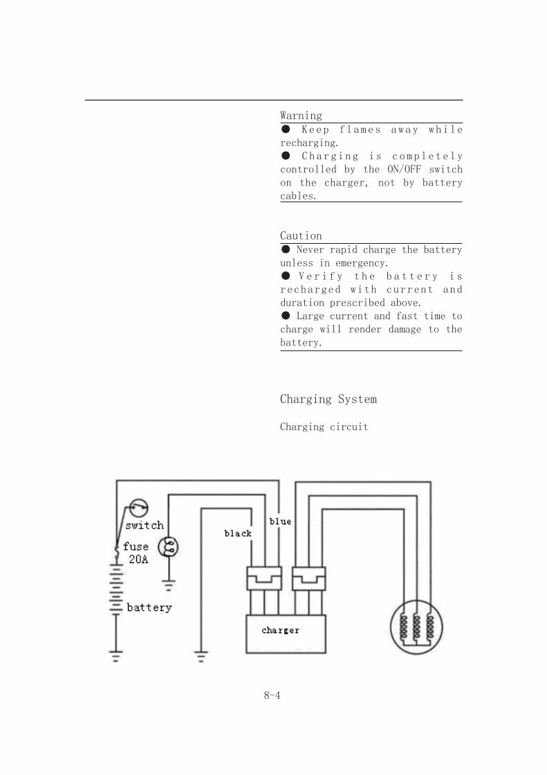
Warning● Keep flames away while recharging.● Cha r g i n g i s c o m p l e t e l y controlled by the ON/OFF switch on the charger, not by battery cables.
Caution● Never rapid charge the battery unless in emergency.● V e r i f y t h e b a t t e r y i s recharged with current and duration prescribed above.● Large current and fast time to charge will render damage to the battery.
Charging System
Charging circuit

8-5
Current Leakage Inspection
Turn the main switch to OFF position, and remove the negative cable terminal (-) from the battery. Connect an ammeter between the negative cable terminal and the battery negative terminal.
Caution● In the current leakage test, set the current range at the largest scale, then gradually decrease to the lower scale as the test process goes to avoid possible damage to the ammeter and the fuse.● Do not turn the main switch to ON position during test.
If the leaked current exceeds the specified value, it may indicate a short circuit.
Allowable current leakage: Less than 1mA
Disconnect each cable one by one and take measurement of the current of each cable to locate the short circuit.

8-6
Inspection on Charging Voltage
Caution● B e f o r e c o n d u c t i n g t h e inspection, be sure that the battery is fully charged. If undercharged, the current changes dramatically.● Use a fully charged battery having a voltage larger than 13.0 V.● While starting the engine, the starter motor draws large amount of current from the battery.
After the engine is warmed up, replace original battery with a fully charged battery.
Connect a digital voltmeter to the battery terminals.
Connect an ammeter between both ends of the main fuse.
Connect a tachometer.
Turn on the headlight to high beam and start the engine.
Accelerate the engine to the specified revolution per minute and measure the charging voltage.
Specified Charging Current:1.2 A / 6000 rpm
Control Charging Voltage:14.5 + 0.5 V / 2000 rpm

8-7
CautionWhen the probe is reversibly connected, use a voltmeter having an indication that the current flows from the positive or the negative direction and the measurement should be at zero, ammeter at one direction only.
Caution● Does not use short-circuit cable.● The main switch shall be turned to OFF position during the process of inspection. Never tamper with the ammeter and the cable while there is current flowing through. It may damage the ammeter.
The following problems are related to the charging system; follow the instructions provided in the checking list to correct it if any one of the problems takes place.
(1)The charging voltage can not exceed the voltage between two battery terminals.(2)The charging voltage and current are too much higher than the standard values.
8-8
The following problems are not related to the charging system; correct it if any by following steps indicate in the checking list.
(1)The standard charging voltage and current can only reach when the revolution of the engine exceeds the specified rpm.-Bulbs used exceed their rate andconsume too much power.-The replacement battery is aged and does not have enough capacity.
(2) The charging voltage is normal, but the current is not.-The replacement battery is aged and does not have enough capacity. -Battery used does not have enough electricity or is over charged.-The fuse of the ammeter is blown.-The ammeter is improperly connected.
(3) The charging current is normal, but the voltage is not.-The fuse of the voltmeter is blown.

8-9
Ignition System
Ignition circuit diagram
C.D.I unitDisconnect connectors of the C.D.I unit.Check the following connectors as indicated in the table at the harness side.
Item Check points Result
Main switch turn to “ON” position
Br/Bl~B Battery voltage
Pulse generator Bl/Y~G/R 50~170Ω
Ignition coil
Primary circuit
Secondary circuit
G/R~B
T E R M I N A L -B~with no cap
T E R M I N A L -B~with cap
2.9±10%Ω
15.0±10%Ω
20.0±10%KΩ
B BlackR RedG Green W White Y Yellow
L Blue

8-10
Inspection on Ignition Coil
Disengage the connector of the ignition coil and the spark plug cap.Measure the resistance between the terminals of the primary winding.
Standard resistance: 2.9Ω ± 10%
Remove the cap from the spark plug and measure the resistance between the spark plug and the primary winding.
Standard resistance:With no cap: 15.0Ω ± 10%With cap: 20.0±10%KΩ
Ignition Coil Replacement
Loosen the lock bolt and replace the ignition coil if necessary.
Inspection of Pulse Generator
Disconnect the coupler of the pulse generator and measure the resistance between the terminals of green/white and blue/yellow.
Standard resistance: 50~170Ω

8-11
Starting System
Starting circuit diagram
Inspection on starter relay
Open the main switch.Press the brake.Push down the starter switch.If a sound of “Looh Looh” is heard, it indicates the relay function normally.
Removal
Remove the seat.Disconnect the negative cable terminal of the battery.Disconnect the cable positive terminal from the relay.Disconnect the positive cable of the starter motor.Disconnect the coupler of the relay.
8-12
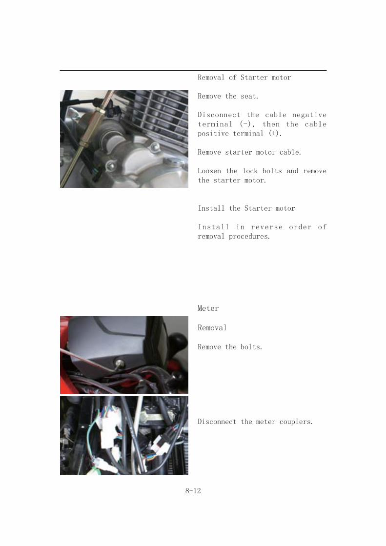
Removal of Starter motor
Remove the seat.
Disconnect the cable negative terminal (-), then the cable positive terminal (+).
Remove starter motor cable.
Loosen the lock bolts and remove the starter motor.
Install the Starter motor
Install in reverse order of removal procedures.
Meter
Removal
Remove the bolts.
Disconnect the meter couplers.
8-13
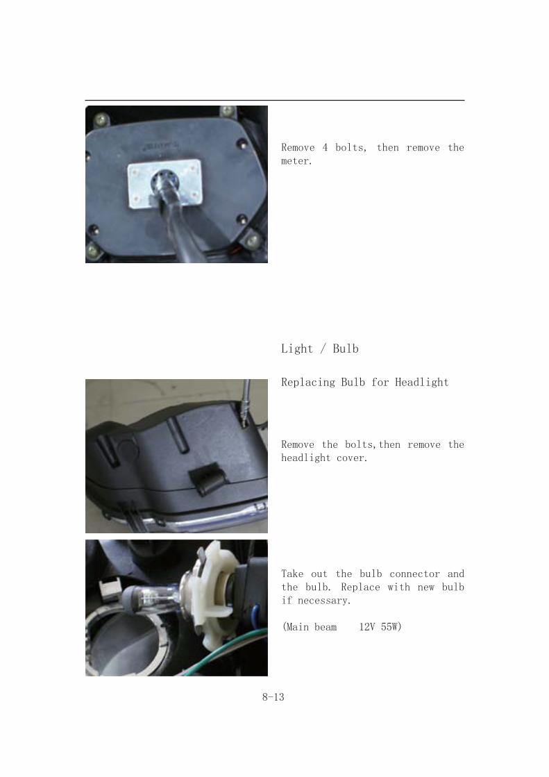
Remove 4 bolts, then remove the meter.
Light / Bulb
Replacing Bulb for Headlight
Remove the bolts,then remove the headlight cover.
Take out the bulb connector and the bulb. Replace with new bulb if necessary.
(Main beam 12V 55W)

8-14
Caution● Never touch the bulb with finger, which will create a heat point.● Clean the fingerprint left on the bulb with alcohol.
Install the bulb of the headlight in reverse order of removal.
Upon completion of replacement, turn on the main switch to ensure the headlight works well.
Adjust the beam and distance of the headlight if necessary.
Replacing the Front winker light Bulb
Pull out the front winker light bulb seat.
Replace with new front winker light bulb.
(12V 21W)
Replacing Bulb of Position Light
Pull out the position light bulb seat.
Replace with new position light bulb.
(12V 5W)
8-15
Replacing Bulb of Taillight
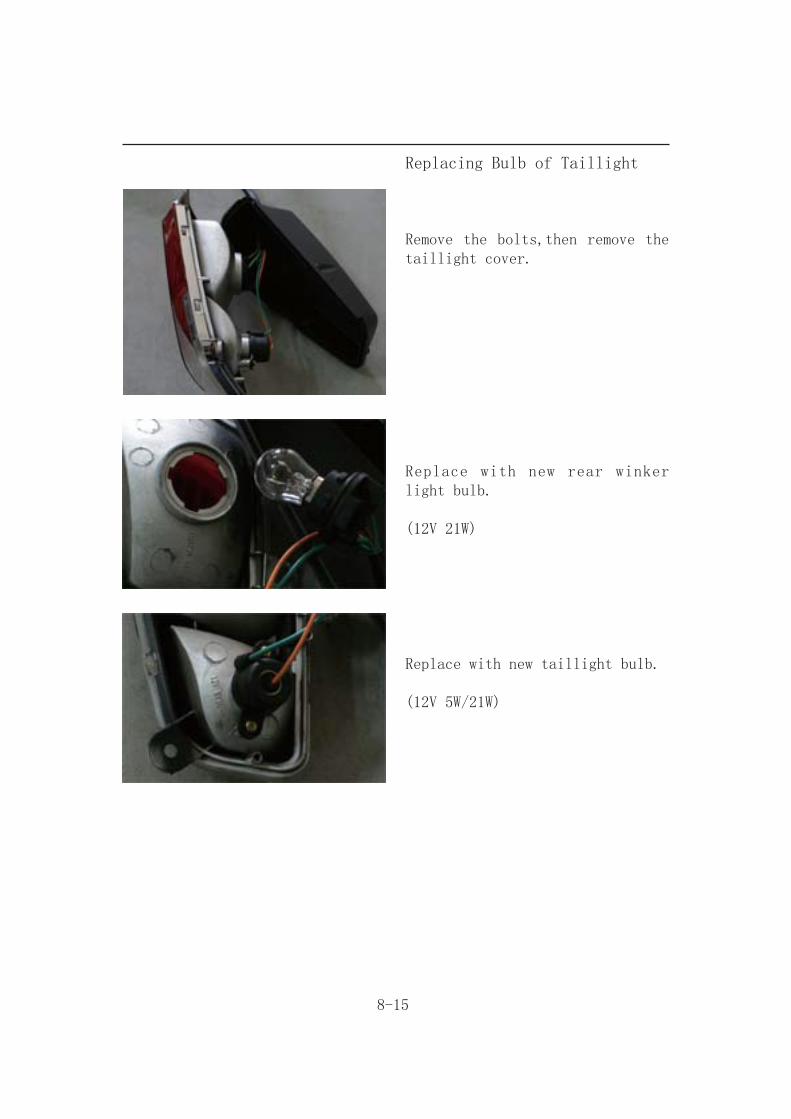
Remove the bolts,then remove the taillight cover.
Replace with new rear winker light bulb.
(12V 21W)
Replace with new taillight bulb.
(12V 5W/21W)
8-16
Switch / Horn
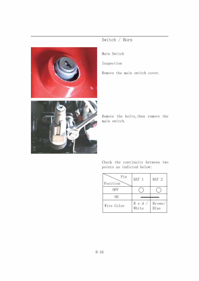
Main Switch
Inspection
Remove the main switch cover.
Remove the bolts,then remove the main switch.
Check the continuity between two points as indicted below:
Pin
PositionBAT 1 BAT 2
OFF
ON
Wire ColorR e d /White
Brown/Blue

8-17
Handle switches
Disconnect the coupler of handle from front fender left side.
Check the continuity between two points as indicated in the table below.
Start Switch
Position
Pin ST SG
Free
Wire ColorBlue/ White
Black
Headlight Switch
Position
Pin
OFF
Wire Color
BAT3 LO HI PL
Red R e d / Green
R e d /Yellow Blue
8-18
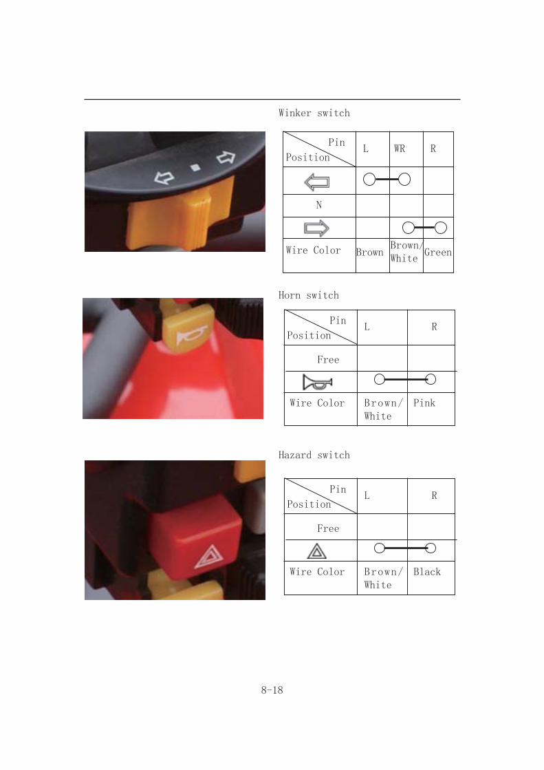
Winker switch
Position
Pin
N
Wire Color Brown/White
Brown
L WR R
Green
Horn switch
Position
Pin
Free
Wire Color Brown/ White
L R
Pink
Hazard switch
Position
Pin
Free
Wire Color Brown/ White
L R
Black
8-19
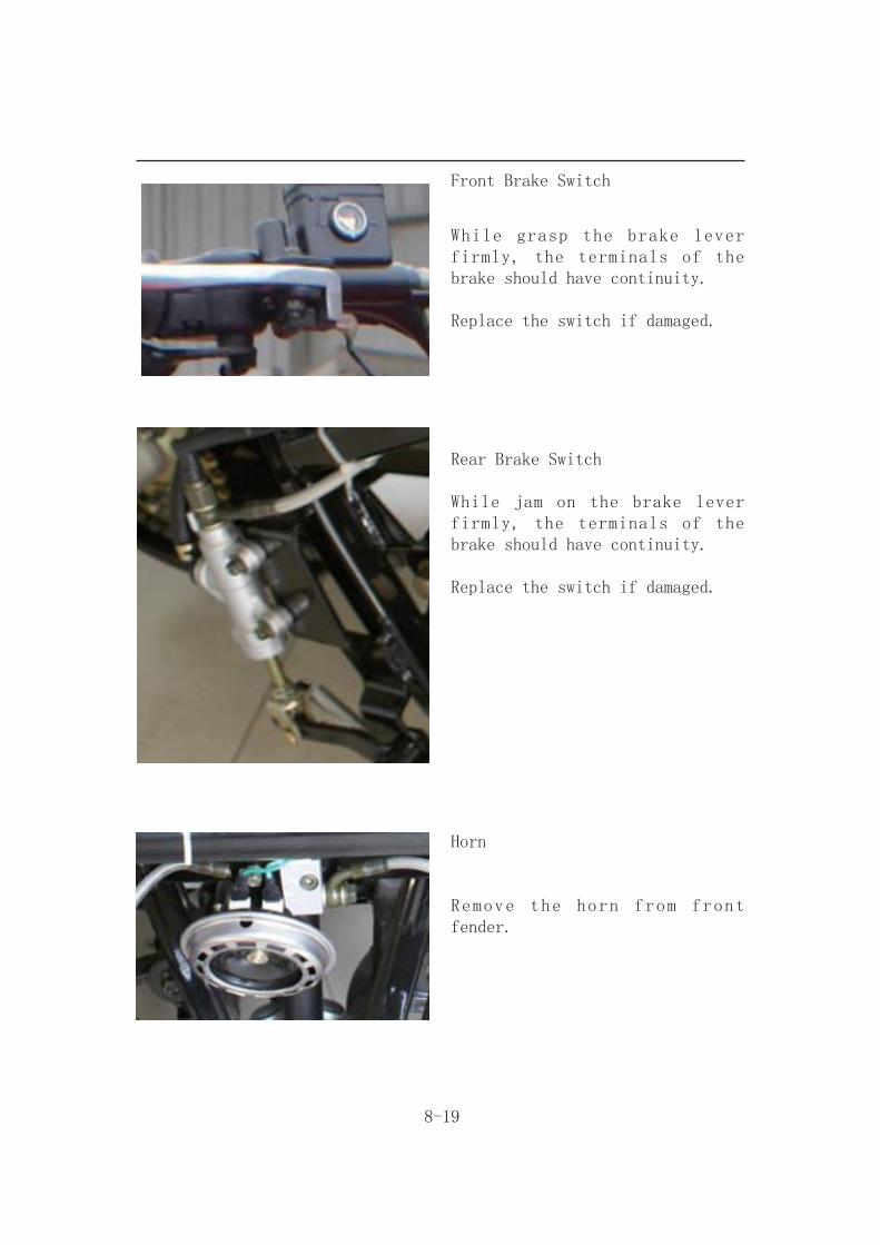
Front Brake Switch
While grasp the brake lever firmly, the terminals of the brake should have continuity.
Replace the switch if damaged.
Rear Brake Switch
While jam on the brake lever firmly, the terminals of the brake should have continuity.
Replace the switch if damaged.
Horn
Remove the horn from front fender.

8-20
Apply 12 V power source to two terminals of the horn, the horn should sound.
Replace the horn if necessary.

