notes on tuning and maintenance of ibis bicycles, rev. c ... · notes on tuning and maintenance of...
TRANSCRIPT

Instruction Manual
Notes on Tuning and Maintenance of Ibis Bicycles, Rev. C (Ripley Edition)
Reprinting Permitted if Source Quoted

2
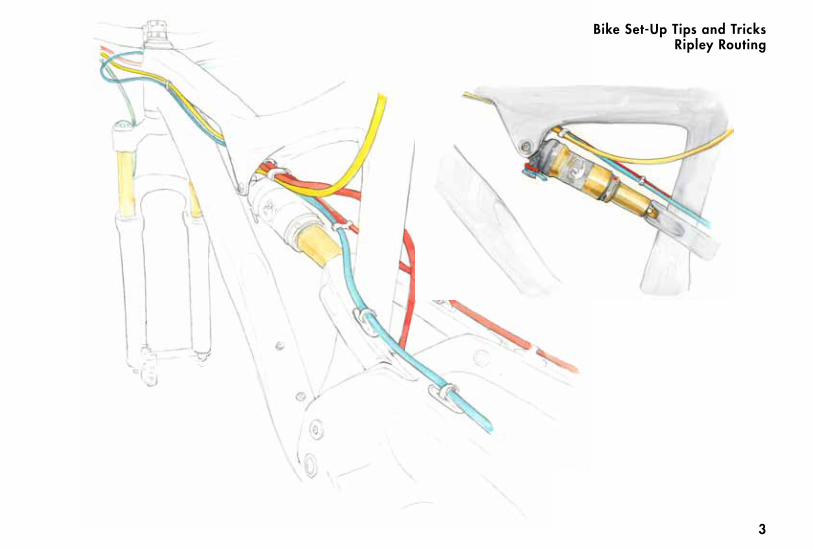
Internal routing is provided for the derailleur cable housing, and for a mechanical dropper cable if you’re not running a front derailleur (otherwise the dropper cable is external). The housing needs to be fished through the frame before you mount the fork. Use your derail-leur housing as a pilot. The housing provided in Ibis build kits is a little longer than you need and works fine as a pilot. With no fork installed, insert the housing into the cable exit hole that is under the upper shock mount. When the cable gets to the head tube, use your finger to guide the cable through the front access hole. We recommend that the rear derailleur cable goes in the left access holes. To keep the cable quiet inside the frame, install three zip ties on the housing about an inch apart, so that they will be located in the middle of the tube when the cable is installed in the frame (to do this, pull the housing out of the top tube and through the top of the head tube about 2 feet, then install the zip ties).
Ripley RoutingBike Set-Up Tips and Tricks
Point the zip ties in different direc-tions. Do not cut the tail off the zip tie. When you insert the housing with zip ties into the frame, the zip ties will prevent the cable from rattling inside the frame. Build the bike with the cables dangling, and when you are ready, feed the derailleur cable through the housing. A cable clip is provided to keep the cable from getting unruly. It should clip onto the two derailleur cables just in front of the seat tube. Once you’ve got your cables routed through the upper shock mount area (up to four cables), put a zip tie around the cables right where they exit that area. The front derailleur cable should be routed on the inside of the clevis. See illustration on the following page.
3
Bike Set-Up Tips and TricksRipley Routing

4
Ripley Routing
Cable RoutingBike Set-Up Tips and Tricks
5
Chain Length To get the correct chain length shift into the large chainring and largest cog and let all the air out of your shock. Thread the chain through the gears and derail-leurs, compress the suspension all the way to bottom out, and cut the chain at the minimum length needed with the rear derailleur stretched out.
Tapered Head TubeThe Ripley features a tapered headtube that works with new tapered steerer forks. Known as mixed tapered, or “ZS44/28.6 | EC49/40” in the Standardized Headset Identifica-tion System. This standard is compatible with both the Chris King IS3 and certain Cane Creek headsets (see our webstore for the offerings.) The Hakkalügi Disc features a tapered steerer too, with the following S.H.I.S identification: IS41/IS52. If you want information about these standards visit www.bicycleheadsets.com.This standard is compatible with both the Chris King Mixed Tapered and certain Cane Creek headsets (see our webstore
for the offerings.)If you’ve already got a perfectly usable fork with a traditional 11/8” steerer tube that you’d like to use, simply install an adapter that will make your fork work on the Ripley. Both Chris King and Cane Creek make adapter style headsets that will adapt our 1.5 cup to your 11/8” fork.For those who like to experiment with head angle and changing steering geometry, Cane Creek now offers a headset called the AngleSet, which is compatible with the Ripley. The AngleSet allows you to adjust the head tube angle of the bike in 1/2” degree increments, from +1.5̊ to –1.5̊ . Rear Dropouts and Disc Brake MountsThe rear axle is called a Maxle (it's 142x12), and is very similar to the new through axle fork axles. The Ripley is designed to bolt a post–mount stan-dard caliper directly to the frame for a 160mm rotor or to a 180mm or 185mm rotor with a post to post style adapter.The derailleur hanger for the Ripley is different than the one found on the Mojo
Carbon, Mojo SL, and Tranny. Replace-ments are available via your Ibis retailer or in the online Ibis store.
Bike Set-Up Tips and Tricks
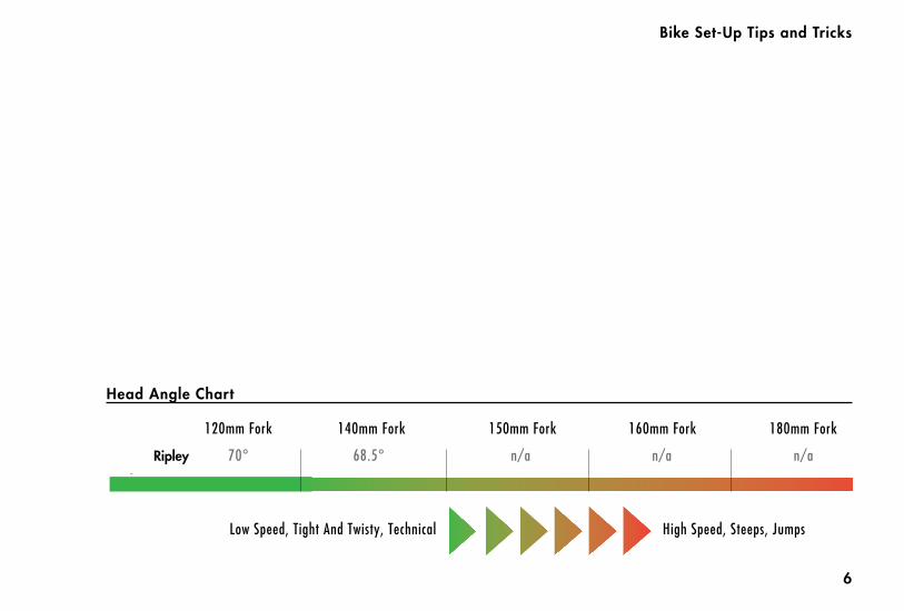
140mm Fork 150mm Fork 160mm Fork 180mm Fork
n/aRipley
Low Speed, Tight And Twisty, Technical High Speed, Steeps, Jumps
69°
68.5°
68.5°
120mm Fork
70°
68.5°
68°
68°
67.5°
67°
67°
n/a
n/a
n/a
n/a
n/a
Mojo SL
Mojo HD140
Mojo HD 160 66°
n/an/a68.5°
Bike Set-Up Tips and Tricks
Head Angle Chart
6
140mm Fork 150mm Fork 160mm Fork 180mm Fork
n/aRipley
Low Speed, Tight And Twisty, Technical High Speed, Steeps, Jumps
69°
68.5°
68.5°
120mm Fork
70°
68.5°
68°
68°
67.5°
67°
67°
n/a
n/a
n/a
n/a
n/a
Mojo SL
Mojo HD140
Mojo HD 160 66°
n/an/a68.5°
7
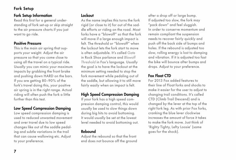
Fork Setup InformationRead this first for a general under-standing of fork set-up or skip straight to the air pressure charts if you just want to go ride.
Positive PressureThis is the main air spring that sup-ports your weight. Adjust the air pressure so that you come close to using all the travel on a typical ride. Usually you can mimic your maximum impacts by grabbing the front brake and pushing down HARD on the bars. If you are getting 80–90% of the fork’s travel doing this, your positive air spring is in the right range. Actual riding will often push the fork a little further than this test.
Low Speed Compression DampingLow speed compression damping is used to reduced unwanted movement and over travel due to low speed changes like out of the saddle pedal-ing and subtle variations in the trail that can cause wallowing etc. Adjust to your preference.
LockoutAs the name implies this turns the fork rigid (or close to it) for out of the sad-dle efforts or riding on the road. Most forks have a “blowoff” so that the fork will move if a large enough impact is felt. The threshold or “blowoff” when the lockout lets the fork start to move is often adjustable. It’s called Gate in Rock Shox parlance and Blowoff Threshold in Fox’s language. Usually the goal is to have the lockout at the minimum setting needed to stop the fork movement while pedaling out of the saddle, but allowing it to still move fairly easily when an impact is felt.
High Speed Compression DampingIf your fork has a high speed com-pression damping control, this would usually be used to slow things down during big hits to avoid bottoming. It would usually be set at the lowest level needed to avoid bottoming out.
ReboundAdjust the rebound so that the front end does not bounce off the ground
after a drop off or large bump. If adjusted too slow, the fork may “pack down” and feel sluggish. In order to conserve momentum and remain compliant the suspension needs to recover fairly quickly and push off the back side of bumps and holes. If the rebound is adjusted too slow, rolling energy is lost to damping and vibration. If it is adjusted too fast the bike will bounce after bumps and drops. Adjust to your preference.
Fox Float CTDFor 2013 Fox added features to their line of Float forks and shocks to make it easier for the user to adjust to changing trail conditions. It’s called CTD (Climb Trail Descend) and is changed by the lever at the top of the right fork leg. As with prior Fox forks, cranking the blue lever clockwise increases the amount of force it takes to make the fork move. Just think of ‘Righty Tighty, Lefty Loosie’ (same goes for the shock).
Fork Setup
8
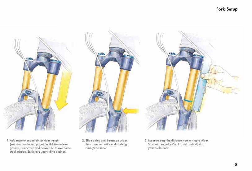
1. Add recommended air for rider weight (see chart on facing page). With bike on level ground, bounce up and down a bit to overcome stock stiction. Settle into your riding position.
2. Slide o-ring until it rests on wiper, then dismount without disturbing o-ring's position.
3. Measure sag–the distance from o-ring to wiper. Start with sag of 25% of travel and adjust to your preference.
Fork Setup

9
Fork Setup
CTDClimb enables a firm low-speed com-pression setting. We’d use it for paved or smooth fire road climbs. Trail mode dials back the low-speed compression damping from climb mode. And once you set the lever to Trail mode, changing between soft, medium, and firm settings on the outer dial enable you to further fine tune the low-speed compression damping (If on Trail mode, we usually prefer the soft setting). Fox recommends the Trail setting for an optimal blend of pedaling efficiency and bike control on variable terrain.Descend mode changes the compres-sion setting to full-open for maximum control and plush performance on steep, aggressive descents.

10
Ripley SagWe recommend the following shock pressures as starting points for the Ripley:< 170 lbs: riding weight less 10psi > 170 lbs: riding weight plus 10psi=170 start with riding weight
Shoot for 11mm (.45") sag.Less pressure gives a slacker seat angle and overall smoother ride. More pressure gives a firmer suspen-sion feel and steeper seat angle and more over the pedals riding position.
Trail AdjustThe new RP23 CTD (Climb, Trail, Descend) is set-up much like the Float CTD fork:Climb mode enables a firm low-speed compression setting. We’d use it for paved or smooth fire road climbs. Trail mode dials back the low-speed compression damping from climb mode. And once you set the lever to Trail mode, changing between soft, medium, and firm settings on the dark outer dial enable you to further fine tune the low-speed compression damping.
Descend mode changes the compres-sion setting to full-open for maximum control and plush performance on steep, aggressive descents. The pedaling efficiency of the dw-link suspension renders many of the features of the RP23 CTD superfluous. For all but smooth pavement or fire road climbing, we recommend run-ning the RP23 in the Descend setting. The increased low speed compression damping that Trail and Climb settings provide cut out much of the small bump sensitivity that our bikes are so well known for.
Adjusting Rebound The RP23 has adjustable rebound damping. It’s adjusted by turning the red dial on the inside of the CTD lever (or ProPedal adjust lever on older RP23s). Generally you want it as fast as you can set it without getting bounced off the saddle after a bump or drop (like riding off a curb in the saddle.) If the rebound setting is too slow the shock will be partially com-pressed when you hit the next bump resulting in “packing down”. Too fast
Rear Shock Setup

11
and the bike will bounce you up in the air after bumps and drops. Adjust to your preference.
ProPedalThis is a damping system used by Fox to minimize unwanted suspension bob. The dw–link suspension is good at minimiz-ing suspension bob but there are situa-tions where you might want to use some ProPedal. It is turned on or off with the simple movement of the easily accessible blue lever at the top of the shock. You can run the shock open or engage the ProPedal settings on any of the shocks.
On the Fly RP23 ProPedal controlsPosition 1: blue lever towards the drive side=shock open, no ProPedal.Position 2: blue lever toward the non–drive side=ProPedal level based on dial setting 1–3.
Kashima RP23The 2012 Kashima shocks have Adaptive Logic, and work differently than the prior RP23's. Set the lever
Rear Shock Setup
to the left, and you have the firmest ProPedal setting. To the right is 0 (open) or ProPedal 1 or 2. The other settings are the same as prior RP23s.

12
Maintenance

13
Maintenance
Working on your RipleyShould you find it necessary to replace any of the bearings on the Ri-pley eccentric linkages, you will need to remove the swingarm. For that, you will need the following tools:• 12mm open end wrench• 15mm socket wrench• 2 x 6mm Allen wrench• 1 x 5mm Allen wrench• 2 x 4mm Allen wrenches
Bearing Replacement:Please refer to the section on Ripley Swingarm Removal on pages 44–45.Ibis will be offering a bearing remov-al tool in addition to a bearing press in mid 2013. Complete instructions will be included in the next version of this guide.
Ripley Bearing Specs:Eccentric Core Inner Bearings:• 6806-2RS (30 x 42 x 7)
These are the same size as BB30 bearings.
Lower outer bearings • 608-RS 8x22x7
These mount in the swingarm and can be found in skate shops.
Upper outerbearing • 698-RS 8x19x6
These mount in the swingarm and can be found in skate shops.
The Ripley uses the following shock and shock hardware:
Upper Hardware: • 21.8mm wide with an 8mm bore
Lower Hardware: • Bushing removed, use provided clevis
bolt
Ripley Shock: 7.25” (184mm) eye to eye1.75” (44mm) shaft travel
All Mojos use the same shock mounting hardware.Upper Hardware: • 21.8mm wide with an 8mm bore
Lower Hardware:• 40mm wide with an 8mm bore

14
Frame HardwareTorque Specs
17 N·m 18 N·m 19 N·m 20 N·m
Mojo, Mojo SL:Front Derailleur Bolt (Clamp Style)
Forward Shock Mount BoltsRear Shock Bolt
Upper Link BoltsBoth Lower Link Bolts
Mojo HD and SL-R: Front Derailleur Bolt (Direct Mount)
Rear Brake Caliper BoltsBoth Lower Link Bolts
Forward Shock Mount BoltsNon QR Seat Binder Bolts
Tranny:Seat Stay Bolts
Slot Machine Bolt (See p. 37)
4 N·m(3 ft·lbs)
5 N·m(3.68 ft·lbs)
10 N·m(7 ft·lbs)
16 N·m(11.8 ft·lbs)
Frame Hardware Torque Specs, by Model
6 N·m(4.5 ft·lbs) (4.5 ft·lbs)
7 N·m 8 N·m(TK ft·lbs)
9 N·m(TK ft·lbs)
16 N·m (12 ft·lbs) for Geared Riding 20 N·m 15 ft·lbs for Single Speed Riding
3-4 N·m
RipleyUpper And Lower Eccentric Core Bolts M8 w/5mm Hex
8 N·m5 N·m
5 N·m
6 N·m
Use with Loctite 242
Use with Loctite 242
Use with Loctite 242
Use with grease for a ss bolt and anti-seize for a titanium bolt.Use with Loctite 242 for a steel pin and anti-seize for a titanium bolt.
Use with Loctite 2425-7N·m with a dab of grease
Use with Loctite 242 for a steel pin and anti-seize for a titanium pin.
Upper Link BoltsRear Shock Bolt Use with grease for a ss bolt and anti-seize for a titanium bolt.
Use with Loctite 242 for a steel pin and anti-seize for a titanium bolt.
Eccentric Shaft BoltsLower Shock to Clevis Bolts
Clevis To Swingarm Bolts4 N·mUpper Shock Mount Bolts
6mm Hex
15
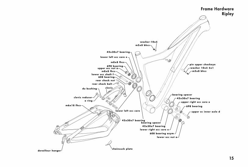
washer-10x5m5x8 bhcs
42x30x7 bearing
lower left ecc core e
m8x8 fhcs
698 bearingupper ecc nut a
m8x8 fhcslower ecc shaft f
608 bearing
rear shock bolt
du bushing clevis
clevis reducero ring
m6x18 fhcs
derailleur hangerchainsuck plate
lower left ecc core
42x30x7 bearing
rear shock nut
bearing spacer42x30x7 bearing
lower right ecc core e
608 bearing asym
lower ecc nut a
698 bearing
upper ec inner axle d
upper right ecc core e
42x30x7 bearing
bearing spacer
pin upper shockeyewasher 10x5 5x1
m5x8 bhcs
Frame Hardware Ripley

16
Ripley Swingarm Removal
Step 1 Put your Ripley in a work stand. Remove the front derailleur,cranks, brakes and the rear wheel.Remove the upper shock bolts (4mm Allen) and lower clevis bolts (5mm). Gently remove the clevis from the swingarm, leaving the shock attached.
Step 2 Remove both of the eccentric core bolts using 6mm allen wrenches.

17
Ripley Swingarm Removal
Step 3 Remove the countersunk bolt from each eccentric core cap. You might need to use a 12mm open end wrench to prevent the eccentric from rotating. Do not use a crescent wrench, cave man!
Step 4 Gently remove the cap, and then you will be able to push the eccentric core out of the frame.

1818
Ripley Swingarm Removal
Note:Special tools are needed to remove and replace the Ripley bearings in the seat tube and in the swingarm. Please do not attempt to remove and replace these bearings. Instructions on removal and rein-stallation of the bearings using a special Ibis manufactured tool will be added to this instruction book at a later date.
To reinstall the swingarm, work in the reverse order. Add grease to the core when reinstalling, and a lightly grease the inner lip of the eccentric cap. Don't forget the two spacers that go between the BB30 bearings in the seat tube. The chamfered hole on the cap aligns with the threaded hole on the eccentric core. Use blue loctite on the bolt.

1919
Ripley Swingarm Removal
Use a 12 mm open end wrench to align the eccentrics so that the flats are hori-zontal and at the 9 o'clock position when the frame is parallel with the ground. Gently slide the swingarm onto the ec-centrics. Insert the swingarm bolts, lower bolt from the non drive side, upper from the drive side. The conehead bolt goes on the lower bolt, on the drive side. Ride it and weep (with joy).