notes on system software - welcome to department of …€¦ · · 2017-08-28using the computer...
TRANSCRIPT
Department of Computer Science Assam University, Silchar
NOTES ON SYSTEM SOFTWARE Mrinal Paul
Mrin@l’$
1 | P a g e
Unit – I
SYSTEM SOFTWARE:
System software consists of a variety of programs that support the operation of a computer.
It is a set of programs to perform a variety of system functions as file editing, resource
management, I/O management and storage management.
The characteristic in which system software differs from application software is
machine dependency.
An application program is primarily concerned with the solution of some problem,
using the computer as a tool.
System programs on the other hand are intended to support the operation and use of
the computer itself, rather than any particular application.
For this reason, they are usually related to the architecture of the machine on which
they are run.
For example, assemblers translate mnemonic instructions into machine code. The
instruction formats, addressing modes are of direct concern in assembler design.
There are some aspects of system software that do not directly depend upon the type
of computing system being supported. These are known as machine-independent
features.
For example, the general design and logic of an assembler is basically the same on
most computers.
TYPES OF SYSTEM SOFTWARE: 1. Operating system
2. Language translators
a) Compilers
b) Interpreters
c) Assemblers
d) Preprocessors
3. Loaders
4. Linkers
5. Macro processors
Machine Structure:
Mrin@l’$
2 | P a g e
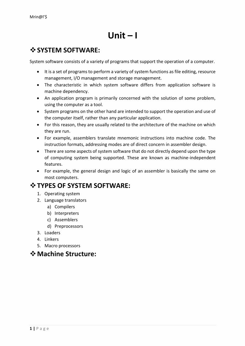
Fig: General hardware organization of a computer system
Memory is the device where information is stored. Processors are the devices that
operate on this information. One may view information was stored as being stored in the
form of ones and zeros. Each one or zero is separate binary digit called a bit. Bits are typically
grouped in units that are called words, characters or bytes. Memory location are specified by
address, where each address identifies a specific byte, word or character.
The component of a word may be interpreted as data (values to be operated) or
instruction (operation to be performed). A processor is a device that performs a sequence of
operation specified by instruction in memory. A program (or procedure) is a sequence of
instructions.
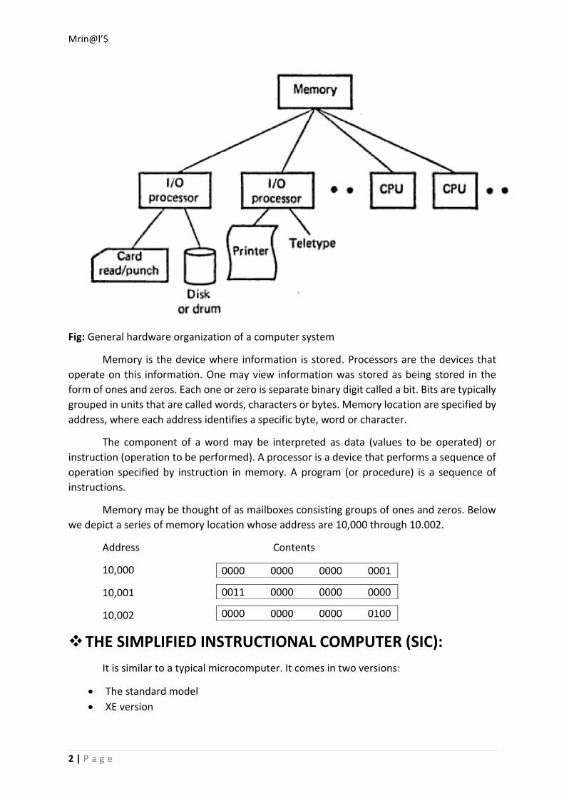
Memory may be thought of as mailboxes consisting groups of ones and zeros. Below
we depict a series of memory location whose address are 10,000 through 10.002.
Address Contents
10,000
10,001
10,002
THE SIMPLIFIED INSTRUCTIONAL COMPUTER (SIC):
It is similar to a typical microcomputer. It comes in two versions:
The standard model
XE version
0000 0000 0000 0001
0011 0000 0000 0000
0000 0000 0000 0100
Mrin@l’$
3 | P a g e
SIC Machine Structure:
Memory:
It consists of bytes (8 bits), words (24 bits which are consecutive 3 bytes) addressed
by the location of their lowest numbered byte.
There are totally 32,768 bytes in memory.
Registers:
There are 5 registers namely
1. Accumulator (A)
2. Index Register(X)
3. Linkage Register(L)
4. Program Counter(PC)
5. Status Word (SW).
Accumulator is a special purpose register used for arithmetic operations.
Index register is used for addressing.
Linkage register stores the return address of the jump of subroutine instructions
(JSUB).
Program counter contains the address of the current instructions being executed.
Status word contains a variety of information including the condition code.
Data formats:
Integers are stored as 24-bit binary numbers: 2’s complement representation is used
for negative values characters are stored using their 8 bit ASCII codes.
They do not support floating – point data items.
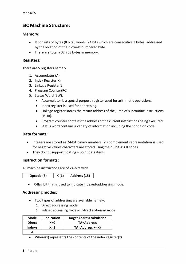
Instruction formats:
All machine instructions are of 24-bits wide
Opcode (8) X (1) Address (15)
X-flag bit that is used to indicate indexed-addressing mode.
Addressing modes:
Two types of addressing are available namely,
1. Direct addressing mode
2. Indexed addressing mode or indirect addressing mode
Mode Indication Target Address calculation
Direct X=0 TA=Address
Indexe X=1 TA=Address + (X)
d
Where(x) represents the contents of the index register(x)

Mrin@l’$
4 | P a g e
Instruction set:
It includes instructions like:
1. Data movement instruction Ex: LDA, LDX, STA, STX.
2. Arithmetic operating instructions Ex: ADD, SUB, MUL, DIB.
This involves register A and a word in memory, with the result being left in
the register.
3. Branching instructions Ex: JLT, JEQ, TGT.
4. Subroutine linkage instructions Ex: JSUB, RSUB.
Input and Output:
I/O is performed by transferring one byte at a time to or from the rightmost 8 bits of
register A.
Each device is assigned a unique 8-bit code.
There are 3 I/O instructions,
1. The Test Device (TD) instructions tests whether the addressed device is ready to
send or receive a byte of data.
2. A program must wait until the device is ready, and then execute a Read Data
(RD) or Write Data (WD).
3. The sequence must be repeated for each byte of data to be read or written.
SIC/XE ARCHITECTURE & SYSTEM SPECIFICATION
Memory:
1 word = 24 bits (3 8-bit bytes)
Total (SIC/XE) = 220 (1,048,576) bytes (1Mbyte)
Registers:
10 x 24 bit registers
Data Format:
Integers are stored in 24 bit, 2's complement format
Characters are stored in 8-bit ASCII format
MNEMONIC Register Purpose
A 0 Accumulator
X 1 Index register
L 2 Linkage register (JSUB/RSUB)
B 3 Base register
S 4 General register
T 5 General register
F 6 Floating Point Accumulator (48 bits)
PC 8 Program Counter (PC)
Mrin@l’$
5 | P a g e
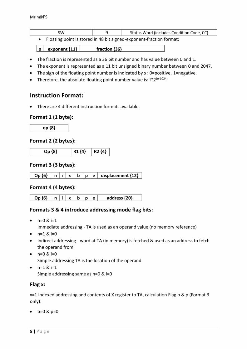
SW 9 Status Word (includes Condition Code, CC)
Floating point is stored in 48 bit signed-exponent-fraction format:
s exponent {11} fraction {36}
The fraction is represented as a 36 bit number and has value between 0 and 1.
The exponent is represented as a 11 bit unsigned binary number between 0 and 2047.
The sign of the floating point number is indicated by s : 0=positive, 1=negative.
Therefore, the absolute floating point number value is: f*2(e-1024)
Instruction Format:
There are 4 different instruction formats available:
Format 1 (1 byte):
op {8}
Format 2 (2 bytes):
Op {8} R1 {4} R2 {4}
Format 3 (3 bytes):
Op {6} n i x b p e displacement {12}
Format 4 (4 bytes):
Op {6} n i x b p e address {20}
Formats 3 & 4 introduce addressing mode flag bits:
n=0 & i=1
Immediate addressing - TA is used as an operand value (no memory reference)
n=1 & i=0
Indirect addressing - word at TA (in memory) is fetched & used as an address to fetch
the operand from
n=0 & i=0
Simple addressing TA is the location of the operand
n=1 & i=1
Simple addressing same as n=0 & i=0
Flag x:
x=1 Indexed addressing add contents of X register to TA, calculation Flag b & p (Format 3
only):
b=0 & p=0
Mrin@l’$
6 | P a g e
Direct addressing displacement/address field containsTA (Format 4 always uses direct
addressing)
b=0 & p=1
PC relative addressing - TA=(PC)+disp (-2048<=disp<=2047)*
b=1 & p=0
Base relative addressing - TA=(B)+disp (0<=disp<=4095)**
Flag e:
e=0 use Format 3
e=1 use Format 4
Instructions:
SIC provides 26 instructions, SIC/XE provides an additional 33 instructions (59 total)
SIC/XE has 9 categories of instructions:
Load/store registers (LDA, LDX, LDCH, STA, STX, STCH, etc.)
integer arithmetic operations (ADD, SUB, MUL, DIV) these will use register A and a word
in memory, results are placed into register A
compare (COMP) compares contents of register A with a word in memory and sets CC
(Condition Code) to <, >, or =
conditional jumps (JLT, JEQ, JGT) - jumps according to setting of CC
subroutine linkage (JSUB, RSUB) - jumps into/returns from subroutine using register L
input & output control (RD, WD, TD) - see next section
floating point arithmetic operations (ADDF, SUBF, MULF, DIVF)
register manipulation, operands-from-registers, and register-to-register arithmetics
(RMO, RSUB, COMPR, SHIFTR, SHIFTL, ADDR, SUBR, MULR, DIVR, etc)
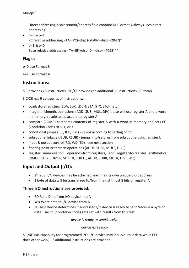
Input and Output (I/O):
28 (256) I/O devices may be attached, each has its own unique 8-bit address
1 byte of data will be transferred to/from the rightmost 8 bits of register A
Three I/O instructions are provided:
RD Read Data from I/O device into A
WD Write data to I/O device from A
TD Test Device determines if addressed I/O device is ready to send/receive a byte of
data. The CC (Condition Code) gets set with results from this test:
device is ready to send/receive
device isn't ready
SIC/XE Has capability for programmed I/O (I/O device may input/output data while CPU
does other work) - 3 additional instructions are provided:

Mrin@l’$
7 | P a g e
SIO Start I/O
HIO Halt I/O
TIO Test I/O
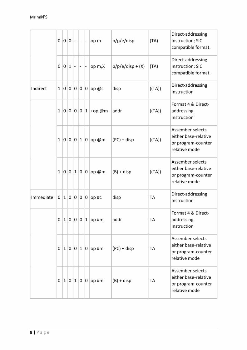
SIC/XE Addressing Modes:
Addressing
Type
Flag Bits Notation
Calculation of
Target Address Operand Notes
n i x b p e
Simple 1 1 0 0 0 0 op c disp (TA) Direct-addressing
Instruction
1 1 0 0 0 1 +op m addr (TA)
Format 4 & Direct-
addressing
Instruction
1 1 0 0 1 0 op m (PC) + disp (TA)
Assember selects
either base-relative
or program-counter
relative mode
1 1 0 1 0 0 op m (B) + disp (TA)
Assember selects
either base-relative
or program-counter
relative mode
1 1 1 0 0 0 op c,X disp + (X) (TA) Direct-addressing
Instruction
1 1 1 0 0 1 +op m,X addr + (X) (TA)
Format 4 & Direct-
addressing
Instruction
1 1 1 0 1 0 op m,X (PC) + disp + (X) (TA)
Assember selects
either base-relative
or program-counter
relative mode
1 1 1 1 0 0 op m,X (B) + disp + (X) (TA)
Assember selects
either base-relative
or program-counter
relative mode
Mrin@l’$
8 | P a g e
0 0 0 - - - op m b/p/e/disp (TA)
Direct-addressing
Instruction; SIC
compatible format.
0 0 1 - - - op m,X b/p/e/disp + (X) (TA)
Direct-addressing
Instruction; SIC
compatible format.
Indirect 1 0 0 0 0 0 op @c disp ((TA)) Direct-addressing
Instruction
1 0 0 0 0 1 +op @m addr ((TA))
Format 4 & Direct-
addressing
Instruction
1 0 0 0 1 0 op @m (PC) + disp ((TA))
Assember selects
either base-relative
or program-counter
relative mode
1 0 0 1 0 0 op @m (B) + disp ((TA))
Assember selects
either base-relative
or program-counter
relative mode
Immediate 0 1 0 0 0 0 op #c disp TA Direct-addressing
Instruction
0 1 0 0 0 1 op #m addr TA
Format 4 & Direct-
addressing
Instruction
0 1 0 0 1 0 op #m (PC) + disp TA
Assember selects
either base-relative
or program-counter
relative mode
0 1 0 1 0 0 op #m (B) + disp TA
Assember selects
either base-relative
or program-counter
relative mode

Mrin@l’$
9 | P a g e
General Machine Structure:

Mrin@l’$
10 | P a g e
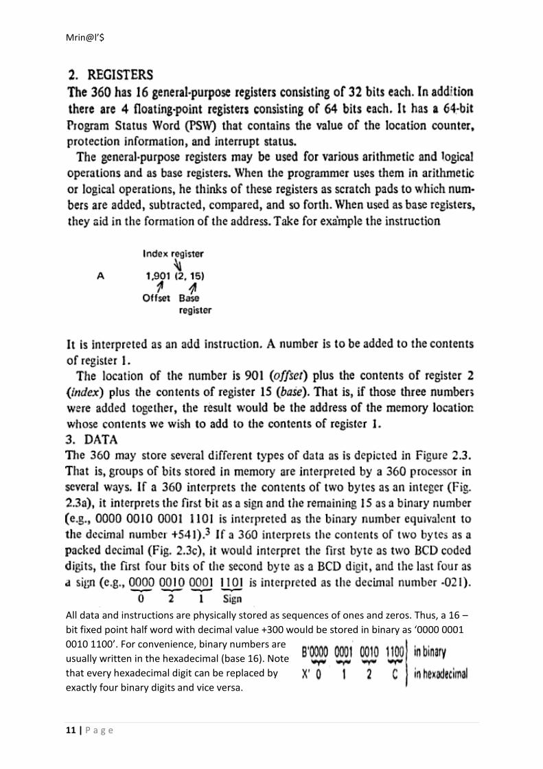
Machine Structure – 360 and 370:
Mrin@l’$
11 | P a g e
All data and instructions are physically stored as sequences of ones and zeros. Thus, a 16 –
bit fixed point half word with decimal value +300 would be stored in binary as ‘0000 0001
0010 1100’. For convenience, binary numbers are
usually written in the hexadecimal (base 16). Note
that every hexadecimal digit can be replaced by
exactly four binary digits and vice versa.

Mrin@l’$
12 | P a g e
Mrin@l’$
13 | P a g e

Mrin@l’$
14 | P a g e
For example, the instruction Add register 3, 4
Q: Write an assembly language program to adding instructions.
Ans.