note to users - university of toronto t-space · 2020. 4. 8. · discrete baseband mode1 for ss/tdm...
TRANSCRIPT
NOTE TO USERS
This reproduction is the best copy available.


CHIP EQUALIZATION AND TRANSMIT
ANTENNA DIVERSITY FOR
HIGH-SPEED SS/TDM SYSTEMS
Farhad Meshkati
Ji thesis subrriitted in coriforrriity with the reyuireme~its for tlic degrcc of blastcr of Applicd Scicncc
Graduate Department of Electrical and Cornputer Engineering University of Toronto
@ Copyright C Farliad hrleshkati, 2001

National Library Bibliothèque nationale du Canada
Acquisitions and Acquisitions et Bibliographie Services services bibliographiques 395 WeYington Street 395, rue Weüington OlmwaON K l A O N 4 -ON KlAONQ Canada Canada
The author has granted a non- exclusive licence dowing the National Library of Canada to reproduce, loan, distribute or sell copies of this thesis in microform, paper or electronic formats.
The author retains ownership of the copyright in this thesis. Neither the thesis nor substantial extracts fiom it may be printed or otherwise reproduced without the author's permission.
L'auteur a accordé une licence non exclusive permettant a la Bibliothèque nationale du Canada de reproduire, prêter, distribuer ou vendre des copies de cette thèse sous la forme de microfiche/füm, de reproduction sur papier ou sur format électronique.
L'auteur conserve la propriété du droit d'auteur qui protège cette thèse. Ni la thèse ni des extraits substantiels de celle-ci ne doivent être impximés ou autrement reproduits sans son autorisation.

Chip Equalization and Transmit Antenna Diversity
for High-Speed SS/TDM Systems
Farhad Meshkati
Master of Xpplied Science, 2001
Department of Electrical and Computer Engineering
University of Toronto
Abstract
Hybrid Spread SpectrumlTime Division Multiplex (SS/TDM) is a promising scheme for
the air interface of future high-speeci wireless packet-based networks, especially for the
downlink. In this thesis, we first present an alternative receiver to the Rake for the
downlink of SSITDhl systems. This receiver, which consists of a Fractionally Spaced
Chip Equalizcr (FSCE) and a dcsprcadcr, is shown to havc supcrior pcrformancc to thc
conventional Rake receiver and can be used in systems with long spreading codes. LVe
propose an adaptive implementation of the FSCE receiver and use simulations to study
the effect of various system parameters on the performance of the receiver. In addition.
for channels wit.h short delay spread in wliich spread spectrum does not provide enough
diversity to combat fading, ive combine chip equalization with transmit antenna diversity
to achieve botli interference suppression arid robustriess agairist fadirig. We dernoristrate
the performance of the conibined scherne iising simulations.

Acknowledgments
1 would like to thank Professor Elvino S. Sousa, my advisor. for his invaluable guidance
and support. 1 am also thankful to the members of the Wireless Lab for the helpful
discussions. 1 am deeply grateful to my family, especially my parents? for their continual
support and encouragement. 1 would also like to acknowledge the financial support of
the Natural Sciences ancl Engineering Research Council of Canada (NSERC) and the
Communications Group.

'To my parents

Contents
Abstract
Acknowledgments
Contents
iii
List of Figures viii
1 Introduction 1
. . . . . . . . . . . . . . . . . . . . . . . 1.1 Direct-Sequerice Spread S y ect runi 2
. . . . . . . . . . . . . . . . . . . . . . 1.2 Spread Spectruin Cellular Networks 5
. . . . . . . . . . . . . . . . . 1.3 hlultipath Fading arid Diversity Tecliniques 6
. . . . . . . . . . . . . . . . . . . . . . 1.4 Receiver Design for CDMA Systems 8
. . . . . . . 1.5 Hybrid Spread Spectruni/Time Division Multiplex (SS/TDh. 1) 10
. . . . . . . . . . . . . . . . . . . . . . 1.6 Thesis blotivation arid Orgaiiization 12
2 The Fractionally Spaced Chip Equalizer (FSCE) Receiver 14
. . . . . . . . . . . . . . . . . . . . . . . . . . . 2.1 SS/TDhl Downlink hlodel 15
. . . . . . . . . . . . . . . . . . . . . . . . . . . . . . . . . 2.2 Signal Detection 18
. . . . . . . . . . . . . . . . . 2.2.1 Optimal Receiver for AWGN Channel 18
2.2.2 Optimal Detection in Presence of Intersymbol Interference (ISI) . . 19
. . . . . . . . . . . . . . . . . 2.2.3 Fractionally Spaced Equalizer (FSE) 19
. . . . . . . . . . . . . . . . . . . . . . . . . . . . . . . . . . 2.3 Rake Receiver 22
. . . . . . . . . . . . 2.3.1 Tapped Delay Line Mode1 for Radio Channels 23
. . . . . . . . . . . . . . . . . . . . . . . . 2.3.2 Rake as a Matched Filter 23
. . . . . . . . . . . . . . . . . . . 2.3.3 Limitations of the Rake Receiver 25
. . . . . . . . . . . . . 2.4 -An Improved Receiver Based on Chip Equalization 27
. . . . . . . . . . . . . . . . . . . . . . 2.4.1 The MMSE Chip Equalizer 28
. . . . . . . . . . . . . 2.4.2 Fractionally Spaced Chip Equalizer (FSCE) 30
. . . . . . . . . . . . . . . . . . . . . . . . . . . . . . . 1.5 Chapter Summary 35
3 Simulation Results for the FSCE Receiver 36
. . . . . . . . . . . . . . . . . . . . . . 3.1 Simulation Mode1 and .A ssumptions 37
. . . . . . . . . . . . . . . . . . . . . . 3.2 Simulation Results and Discussions 43
. . . . . . . . . . . . . . . . . . . . . . . . . . . . . . . . . . 3.2.1 QPSK 44
. . . . . . . . . . . . . . . . . . . . . . . . . . . . . . . . . 3.2.2 lGQ.Abl 53
3 .23 Corriparisori Betweeri QPSK and 16-Q.AA.1 . . . . . . . . . . . . . . 54
. . . . . . . . . . . . . . . . . . . . . . . . . . . . 3.2.4 Correlated Fading 60
. . . . . . . . . . . . . . . . . . . . . . 3.2.5 Decisiori-Feedback Equalizer 60
. . . . . . . . . . . . . . . . . . . . . . . . . . . . . . . 3.3 Cliapter Summary 62
4 Combined Transmit Antenna Diversity and Chip Equalization 64
. . . . . . . . . . . . . . . . . . . . . . . . . . 4.1 .l lar~iou t i's Diversity Scl~errie 66
4.2 Trarisrriit Axiterrria Diversity ivith Cliip Equalizatiori for SS/TDM Systerris 68
. . . . . . . . . . . . . . . . . . . . . . 4.3 Simulation Results ancl Discussions 74
. . . . . . . . . . . . . . . . . . . . . . . . . . . . . . . 4.4 Chapter Summary 76
5 Conclusions 77
.. . . . . . . . . . . . . . . . . . . . . . . . . . . . . . . . . 5.1 Thesis Surrirriary l i
. . . . . . . . . . . . . . . . . . . . . . . . . . . . . . . . . . . .5 .2 Future Work 79

A The Recursive Least Squares (RLS) Algorithm
Bibliography
vii

List of Figures
. . . . . . . . . . . . . . . 1.1 Basic baseband mode1 for DS Spread Spectrum 2
1.2 Demonstration of the noise (interference) rejection property of spread spec-
trum . . . . . . . . . . . . . . . . . . . . . . . . . . . . . . . . . . . . . . . 3
. . . . . . . . . . . . . . . . . . . . . . . . 1.3 Time-varying multipath channel 6
. . . . . . . . . . . . . . . . . . . . . . . . . . 1.4 Fraiiie structure in SS/TDkI 11
. . . . . . . . . . . . . . . . . . . . . . . 2.1 Tratismitter for SS/TDM systems 16
. . . . . . . . . . . . . . . . . . . . . . . . . . . . . . . . . 2.2 hlatched Filter 18
. . . . . . . . . . . . . . . . 2.3 klatched Filter plus Lirlear Transversal Filter 19
. . . . . . . . . . . . . . . . . . . . 2.4 Iiifinitely long LTF with T tap spacing 20
2.3 r\liasing cffccts duc to insufficicnt sanipling rate . . . . . . . . . . . . . . . 21
. . . . . . . . . . . . . . . . . . . 2.6 Tappcd dclay linc modcl of radio channcl 24
. . . . . . . . . . . . . . . . . . . . . . . . . . . . . . . . . . 2.7 R.akc R.cccivcr 2.5
. . . . . . . . . . . . . . 2.8 .-\ri alternative representation of the Rake receiver 26
. . . . . . . . . . . . . . . . . . . . . . . . . . . 2.9 The &Il[SE chip equalizer 29
. . . . . . . . . . . . . . . . . . . 2.10 The chip eclualizer as a tapped delay line 31
2.11 The FSCE receiver . . . . . . . . . . . . . . . . . . . . . . . . . . . . . . . 32
2.12 Plot of 1 Hrll (w)12 for r = Tc . . . . . . . . . . . . . . . . . . . . . . . . . . 34
2.13 Plot of IHT, (w)12 for r = :Tc . . . . . . . . . . . . . . . . . . . . . . . . . . 34
3-1 Discrete baseband model for SS/TDiLI downlink transmitter . . . . . . . . 40

Discrete baseband mode1 for SS/TDM downlink with FSCE receiver . . . . 41
QPSK constellation . . . . . . . . . . . . . . . . . . . . . . . . . . . . . . . 44
Comparison between the FSCE and Rake receivers (Ar = 4, two-path chan-
ne1 with T = 2Tc, QPSK) . . . . . . . . . . . . . . . . . . . . . . . . . . . . 45
Comparison between the FSCE and Rake receivers ( N = 16: two-path
channel with T = 2Tc, QPSK) . . . . . . . . . . . . . . . . . . . . . . . . . 46
Effect of processing gain, N : on the performance of FSCE (two-path chan-
ne1 with T = 2Tc, q = 2,r'l.i = 15, QPSK) . . . . . . . . . . . . . . . . . . . 48
Performance of the Rake receiver under three different channel profiles
(IV = 4, II: = 1, QPSK) . . . . . . . . . . . . . . . . . . . . . . . . . . . . . 50
Performance of the FSCE receiver under three different channel profiles
(N = 4, K = 1, q = 2,121 = 15, QPSK) . . . . . . . . . . . . . . . . . . . . 51
Effect of ISI on the performance of the FSCE receiver (two-path channel,
q = 2 , M = 15, QPSK) . . . . . . . . . . . . . . . . . . . . . . . . . . . . . 52
16-QAM constellation . . . . . . . . . . . . . . . . . . . . . . . . . . . . . 54
Comparison bctwccn the FSCE and Rakc rcccivcrs (Ar = 4, two-path chan-
ncl with T = 2Tc, 16-Q-4M) . . . . . . . . . . . . . . . . . . . . . . . . . . a5
Effcct of proccssing gain: N, on the pcrformancc of the FSCE rcccivcr
(two-path channcl with T = 2Tc, q = 2. -44 = 15, 16-QUvI) . . . . . . . . . 56
Effect of ISI on the performance of the FSCE receiver (two-path channel,
q = 2, LI1 = 15. 16-Q.AM) . . . . . . . . . . . . . . . . . . . . . . . . . . . . 57
Comparison between QPSK and 16-Q-AM (two-path channel witli T = 2Tc,
q = 2 , M = 15) . . . . . . . . . . . . . . . . . . . . . . . . . . . . . . . . . 59
Effect of correlated fading (two-path channel, N = 4. K = 1, q = '2: 1bl = 15) 61
Comparison between FSCE and DFE (two-path channel with T = 2Tc,
11; = 4. IC = 1. QPSIO . . . . . . . . . . . . . . . . . . . . . . . . . . . . . 63

4.1 Transmitter and receiver structures for -4lamouti's diversity scheme . . . . 68
4.2 Block diagram of the receiver for the combined scheme . . . . . . . . . . . 72
4.3 The overail receit-er for the combined transmit diversity and chip equaliza-
tion scheme . . . . . . . . . . . . . . . . . . . . . . . . . . . . . . . . . . . 73
4.4 Cornparison between simple equalization and combined chip equalization
with transmit diversity (two-path channel with T = 0. lTc: N = 4. K = 1) . 75

Chapter 1
Introduction
The possibility of being able to offer multimedia services to mobile users anywhere and
at anytime has attracted enormous amount of attention and effort towards the area of
wireless communications. Multimedia applications such as Internet browsing arid video
coriferencing require high bit rates. In order to provide such services to a large number
of users over the liniited radio spectrum. the spectral efficienq. of wireless systerns has to
improve corisiderably. To desigri efficient wireless networks. it is esseiitial t ha t baridwidtli
arid trarisriiit power are rnariaged efficieritly. Towards this goal. spread spectrurri tecli-
niques tiü\-e received a great deal of att.eiitiori over t.he past feu- years. Iri this modulation
schtmc. the data signal is transmitted over a bandwidth that is much larger than the
data rate. This bandwidth esparision results in a number of properties of whicli interfer-
cncc rejection (suppression) is of primarj- importance. There are different tj-pes of sprcacl
spectrum. The three main ones are Direct-Sequence (DS): Frequency-Hopping (FH) and
Time-Hopping (TH) [II. Direct-Sequence Spread Spectriim (DS-SS) is the most popular
form of sprcad spcctrum and will bc our focus throughout this work.

spreading code Interference
*
spreading code
channel
Figure 1.1: Basic baseband modcl for DS Sprcad Spectrum
1.1 Direct-Sequence Spread Spectrum
Iri Direct-Seqtierice Spread Spectrum (DS-SS), the data signal is rriultiplied by a spreading
code wtricti has a much larger baridwidth thari the niininiurri baridwicltti typically required
for the given data rate. The spreading code should have noise-like properties to achieve
robustness against interference. -At the receiver, the DS signal is multiplied by the same
spreading code. This wax the information signal is despread back to its originaI band-
wicltli. But. the noise (interference) that was added in the channel remains spreacl over
thc largcr bandwidth. The rcsulting signal is thcn passcd through n lowpass filtcr (sce
Figurc 1.1). Thc output of the lowpass filtcr contairis only a fraction of the noisc powcr.
This noise rediiction is proportional to the amoiint of bandwicith cspansion (sec? Figure
1.2). The spreedirig code is normally n bina- pseudo random signal grneratecl by a sliift
register circuit with feedback connections. The binary pulses of this signal are referrecl
to as chips. The ratio between the symhol duration (7') and the cliip duration (Tc) is
called the processing gain and is an important factor in determining the performance of
the spread spectrurn modulation.
-4s a result of the bandwidth expansion, spread spectrum has a number of benefits

data signal ? SS signal
> -L
/ -L frequency
T I
interference f SS signal
/
I -L frcquency T
s~recid interference 1 r: I despread data signal
-L frequcncy T C
Figure 1.2: Demonstration of the noise (interference) rejection property of spread spec-
t rum

[l]: The main one is the interference rejection property. In addition. spread spectrum
provides anti-jamming capabilities. If the bandwidth of t.he SS signal is larger than the
coherence bandwidth of the cbannel, spread spectrum provides path diversity which can
be esploited to combat fading. Another benefit of spread spectrum is that because of
the low power spectral density, SS signals cannot be easily intercepted. AIso: due to
the use of randonl spreading codes, spread spectrum provides some level of secrecy. In
addition, the interference rejection (suppression) property of the spread spectrum allows
for multiple signals to be transrnitted sirnultaneously over the radio channel and hence
provides multiple access cayabilities. Multiple access communication can be achieved by
assigiiirig differerit spreadirig codes to different users. It is desirable that the spreadirig
codes have a narrow aut.ocorrelation function and the cross correlation betweerr different
spreading codes be as srnall as possible to reduce the amount of multiple access interfer-
ence. This multiple access scheme is called Spread Spectrum Multiple -1ccess (SS'Uf-4) or
Code Division Slult.ip!e Access (CDLIA) [2].
The spreading codes used for different users m a j be long or short depending on their
pcriod. If the pcriod of the scqucncc is cqual to the data syrnbol pcriocl the scqucncc
is callcd short. On the otlicr hand: if thc pcriocl is much largcr than t h data symbol
periad, t,hc sccliicncc is long. Also, dcpcnding on thc systcm dcsign. a SSM-1 systcm can bc
synchronous or asynchronous at thc chip lcvcl. In point to multipoint communication (cg.
hase station to mobile t.ertninals). it is possible to synchronize signals iit the cliip level.
This way. orthogonal spreacf ing codes can he useci t o eliminate CO-channel in terference
(orthogonal CDhl-A). U,.alsh codes are esamples of ort hogorial sprcading codes. N'hile
\j7alsh codes provide orthogonalit~v, they do not have noise-like properties such as narrow
autocorrelation function. To rectify this problem: a masking sequence can be used to
randomize the spreading codes while keeping ttieir orthogonality. In multipoint t o point
communication (mobile tcrminals to base station) it is difficult to synchronize the signals
transini tted by different users. In such cases, asynchronous transmission with short or

long pseudo noise (PX) spreading codes is used. This way? little coordination is required
among the users.
1.2 Spread Spectrum Cellular Networks
Because of its robustness against jamming, low probability of intercept and moderate
level of secrecy (encryption), spread spectrum was used mainly in military applications.
In 1978, cellular application of spread spectrum was proposed for the first time [ 3 ] . Due
to its noise rejection capability, spread spectrum reduces the intracell and interceIl inter-
ference and alion-s the entire available bandwidth to be used in every ce11 (i-e. frequency
reuse factor of one). This results in a higher system capacity compared to narrowband
modulation schemes. The capacity of spread spec trum cellular ~ietworks depends on the
level of intracell and interccll interference. Several approaches are taken to increase the
systerri capacity:
One technique is to use potver coritrol to rniriimize the aniount of iriterfererice iri the
system by adjusting the transmit pon7er according to the channel condition while satisfying
the required signal to noise ratio (SNR) level. -4nother approach is to use sectorization
along with directional antennas to reduce the interference. Ir1 the downlink (base station
to mobile) where communication is point to miiltipoint, signals can be synchronizecl at
the chip level. With synchronization, orthogonal spreading codes can be used to elimitiate
intraccll intcrfcrcncc. -41iothcr approach is to improvc tlic design of rcccivcrs so that tiicy
can achicvc thc dcsircd bit crror rates a t lowcr SNR lcvcls. This rcdiiccs thc rccliiircd
transmit power and hence reduces the overall interference in t,he system. .A11 of t h e above
techniqiies try to rnasirnize the system capacity hy minimizing the interference in the
system.

Figure 1.3: Time-varying multipath channel
1.3 Multipat h Fading and Diversity Techniques
hlultipath fading, which is a result of constructive and destructive combination of ran-
domly delayed! refiected. scattered and diffracted signal components (see Figure 1.3), is a
characteristic of almost al1 wireless channels and has to be given serious consideration in
the design of wireless networks. Variations in the envelope of the received signal result in
variations in thc rcccivcd SXR. Whcn the rcccivcd SNR is highcr than thc rcquircd SNR,
the unnecessary interference causes capacity rediiction. One the ot her hand, when the re-
ceived SNR is lower t hm the reqiiired SNR, the reqiiired qiiality of service cannot be niet.
Therefore, steps shoiild be taken to reduce the effect of fading and avoid fluctuations in
the SNR level. The rate of signal variation depends on the channel Doppler spread which
is related to a/,, ivhere 7: is the velocity of the receiver or transmitter or the siirroiinding
objects: c is the velocity of light and f, is the carrier frecpency. The coherence time of the
channel (rCoh), which is a measure of the time interval over mhich a transmitted signal will
be relatively undisturbed bÿ channel fluctuations. is approsimately equal to the inverse
of t.he Doppler spread.
The time dispersion caused by the channel as a resiilt of multipath propagation is
measured by the channel delay spread. The coherence bandwidth of the channel (f,,,,),

which measures the minimum frequency separation required for two signals to undergo
uncorrelated fading, is inversely proportional to the channel delay spread. If the signal
bandwidth is larger than the coherence bandwidth of the channel, fading is frequency
selective. In this case, although the channel causes dispersion in time, most of the signal
energy can be recovered at the receiver through proper signal processing. CVith spread
spectrum modulation, if the information signal is spread over a bandwidth larger than the
coherence bandwidth of the channel, fading becomes frequency selective. This provides
implicit path diversity ndiich can be esploited to combat fading. If the signal banciwidth
is smaller t han the coherence bandwid t h of the channel, fading is frequency non-select ive
(flat fading). Iri this case, the received signal eriergy cau fluctuate corisiderably deperidirig
on the relative phase of the rnultipatli components. To mitigate flat fading, diversity
techniques have to be used.
There are three main diversity rnethods: frequency, time and space. In frequency diver-
sity, multiple copies of the same signal are transmitted using different carrier frequencies.
In order to ensure independent fading? t,he spacing between the carrier frequencies niust
bc largcr than thc cohcrencc frcqucncy of thc channcl. Path diversity which is proviclcd in
sprcad spcctrum techniques can bc considcred as a spccial case of frcqucncy divcrsity. In
tinlc divcrsity, multiple copies of thc samc signal arc scnt diiring ciiffcrcnt timc slots. Tlic
scparation bctwccn thc timc slots should bc largcr than thc cohcrcncc timc of thc channcl
to ensure independent fading. Spme diversity is achieved iising multiple antenniis. One
cornmori way is to transmit the signal usirig one transmit antenna and receive the sigiial
with multiple receive antennas. If the receive antennas are positioned far enough [rom
each other. they \vil1 provide space diversity. It should be notecl that even if the signals
undergo correlated fading, there is still some diversity gain. However, the diversity gain
reduces as the correlation increases.
Due to the stringent limitations on the size and complexity of the mobile terminals.
receive antenna diversity is not very practical for the downIink charinel. Instead, it is

preferred to use transmit diversity. Most of the proposed transmit antenna diversity
schemes result in handwidth espansion or require feedback. -4lamouti in [4] and DaSilva
and Sousa in [5] have proposed two different transmit diversity techniques for Bat fading
channels. Alamouti uses a special case of space-time coding [6] to achieve diversity whereas
DaSilva and Sousa rotate the constellation t o obtain resistance against fading. Both
metliods are bandnidth efficient and do not require feedback. -4 rnodified version of
Alamouti's scherne has been proposed in [Tl for channels with ISI. The proposed scheme
is mainly concerned wi t h narrowband modulation and does not consider spread spectrum
modulation.
1.4 Receiver Design for CDMA Systems
We mentioned that one approach for increasing tlie capacity of spread spectrum cellular
rietworks is to irriprove the receiver design. -411 improved receiver cari satisfy the quality
of service requirernent a t a lower SNR level. This reduces the overall iriterfererice iri the
system and hence increases the capacity. The conventional receiver for spread spectrum
systems is the Rake receiver [8]. While it is simple and robust, Rake receiver performance
is limited by interference. New receivers have been proposed to mitigate tlie sliortconi-
ings of the Rake receiver [9]. These receivers can be divided into two main categories:
mult.iuser and single-user. The first multiuser detector was proposed by Verdu in 1986
[IO] and IWS bascd on hlilsinium Likclihood Sequcncc Dctcçtion (MLSD). Although t liis
rcccivcr can achicvc optimum pcrformancc. it is not practical duc t o its cxponcnt,ial com-
plesity. -4 niimber of siihoptimal reccivers have been proposed which are less comples to
implement . Decorrelator receiwr [l 11. Siiccessive Interference Cancellation (SIC) 1121 and
Parallel Interference Cancellation (PIC) [13] are examples of such suboptimal receivers.
In al1 multiuser receivers, the signal for each user is demodulated taking into account the
contribution of other users (interferers) in the system. Most of these receivers require ver'-

high computational power and hence are not suitable for the downlink. Froni a practical
point of view? size. complexity and cost of mobile terminak should be kept as Iow as
possible.
-4 single-user receiver, on the other hand, does not require any information regarding
other users in the system and demodulates the data signal of one user only. One family
of improved single-user detectors is the Minimum Mean Square Error (Mh.ISE) receiver
proposed in [14] and [ls]. These receivers have moderate complexity but the? require the
received signal to be cyclostationary. Therefore, they can only he used in systems with
short spreading codes.
-4 nuniber of receivers have beeri yroyosed for systerris with long spreading codes
116. 17, 18. 191. Ttiese receivers use chip equalization to suppress interferericc ic i the
downlink of CDhL4 systems. In [20]: Davis et al. present chip equalization as a noise
whitening approach for multiple-access noise rejection. CIiip equalization based on Zero
Forcing (ZF) and iLlinimum Meari Square Error (MhISE) criterion is discussed in [16]:
[18] and [19]. Several adaptive implenientations of chip equalization are also presented in
[lS], [21] and [22] for thc downlink of CDhjIA systcms.
Whilc chip cqualization is shown to givc supcrior pcrformancc cornparcd to t h con-
vcntional R.akc rcccivcr. thc pcrforniancc of siich rcccivcrs has not bccn sttidiccl in dctail.
hIorc rcscarch nccds to bc donc in ordcr to obtain furthcr insight into thc opcration of
these receiwrs. For esample, t he effect of varioiis system parameters siich as processing
gain and channel profile on the performance of tliese receivers needs to investigated. In
order to achieve high bit-rate transmission, the spectral efficiency of wireless systems hm
to improve. One possibility is to try to use Iiigh-order modulations siich as 16-QAM.
So far: no work has been done to study the performance of chip equalizers under such
modulation schemes.

1.5 Hybrid Spread Spectrum/Time Division Multi-
plex (SS/TDM)
Future wireless networks are espected to support various multimedia services. A large
portion of the traffic carried by these networks will be data-oriented. In contrast to voice.
which requires a constant bit rate and is sensitive to delay, data traffic is bursty in nature
and tolerant to delay. Current wireless systems (Le. 2G) are not particularly optimized for
data transmission. For example. the DS-CDhI-4 scheme that is employed in the downlink
of IS-95 standard is dcsigncd mainly for voicc transmission. Each uscr is assigncd onc
orthogonal code (Walsh codc) ovcr which thc uscrk information is sprcad. This way. a
voice channel is allocated to a user over the entire diiration of its call.
In contrast to voice services that use circuit-switching to guarantee continuous trans-
mission. data services can use packet-switching methocls to achieve higher efficiencies by
taking advantage of statistical multiplesing. Therefore, if a wireless network is to be
designed esclusively for packet transmission. it is reasonable to incorporate some form
of time multiplesing. This allows us to use fairly simple scheduling schemes to accom-
mociate both high bit-rate and low bit-rate users in the system. However. we would still
like to have some of the advantages of spread spectrum. In particular. we want to have
some degree of robustness against interference. Spread spectrum reduces the intracell
and intercell interference and allows us to use a frequency relise factor of one. LVe c m
have the benefits of both TDM.1 ancl spread spectrum by implementing a hybrid Spreaci
Spectrum/Time Dix-ision Multiples (SS/TDhI) scheme. In such a SS/TDM scheme. tin-ie
is divided into slots (frames). During eacti time slot, spread spectrun~ moclulation is usect
for data transmission. This way, users receive (or transmit) data in bursts rather than
continuously. Each frame contains one or more pilot bursts as shown in Figure 1.4. The
pilot bursts facilitate various tasks such as acquisition, synclironization. channel estima-
t ion, and signal to noise ratio (SNR) rrieasurement. Considering its structure: SS/TD LI is

I Time Slot (frame) Pilot Burst
Figure 1.3: Frame structure in SS/TDh,I
more feasible in point to multipoint communication wliere time synchronization is easier
to achieve. Implementing this scheme in multipoint to point scenarios is more difficult
and rleeds coordination among different users. Our focus throughout this thesis wilI be
the downlink (base station to mobile terminal) where the communication is point to mul-
tipoint,
The SS/TDM scheme is particularly suitable for cellular data networks due to the
following reasons:
The time niultiplex nature of this sctieme is very fitting for packet transmission.
It allows us to use schedulirig rriettiods to serve niobile users witli differerit bit-rate
requirenierits in a n efficient nianrier.
Because spread spectruni transmission is used iri each time slot, this scheine still
lias rohstriess agairlst iriterfereiice. I t . lierice? allows ttie entire available bariclwidth
to be used iri every ce11 (i.e. reuse factor of orle).
Sirice duririg auy giveri frarrie, o d y orle user receives (or trarisriiits) data, the traris-
riiissiori cari be optirriized for tlie user of iriterest. For esariipte: beariiforuiing cari
be dorie usirig ariteriria arrays tu reduce iriterfererice in the system.
If the size of the frames are chosen to be less tliaii the coherence time of the chaririel
(rCoh ). the tinie-varyirig radio charinel becoriies practically tirrie-irivariatit duririg a
frame period. This nrill allow for implementation of sophisticated signal processing
schemes nithout adding too nuc ch cornplexity.

Each user receives (or transmits) data in bursts. So, when a user is inactive, it can
either go to "sleep" mode to save power or process the data it already received.
There are different ways to implernent spread spectrum within each tinie slot. In
order t o support high bit rates and a t the same time keep the processing gain reasonably
large, multi-code DS-SS can be implemented in each time slot. In particular, in the
downlink mhere the signais can be synchronized at the chip level, orthogonal spreading
codes (e-g. IValsh codes) may be used to eliminate intracell interference. In practice,
however, mult ipath propagation destroys the ort hogonality and degrades the performance.
A SS/TDM system with Walsh spreading codes is somewhat similar to the scheme used
in the downlink of 1s-95 [2], [23]. However, tiie niain difference is that in the SS/TDM
system, users receive data in bursts. During each burst, al1 the \ITalsh codes are assignecl
to the sanie user. -An esample of such a SS/TDhl system is the High-Data-Rate (HDR)
system developed by Qualcomm lncorporated [24].
1.6 Thesis Motivation and Organization
Future wireless systems will have to support a variety of services? a majority of which
will be data-oriented. Most data applications have bursty and asyrnmetric traffic. In
many of tliese applications, the downlink traffic is greater than the uplirik traffic. In the
previous section! we ga'-e motivations for using SS/TDhl scheme in future wirelcss data
netn-orks, especially for tlie downlink. One approach is to use orthogonal spreading codes
to eliminate intracell ititerference. However, in practice, inultipat h propagation destroys
tliis ortliogoriality and results iri iriterpath arid ititerchartriel iriterfererice. Our objective
is to propose an alterriative receiver t o the Rake for tlie dowilirik of SS/TDhI systeriis to
cope with this iriterference better. Such a receiver should have rnoderate complexity and
be able to handle long spreading codes. Mre intend to study the effect of different system
parameters on the performance of this receiver. In addition, for channels with short delay

spread. in which spread spectrum may not provide enough robustness against fading, we
add antenna diversity to combat fading.
The organization of the thesis is as follows:
In Chapter 2, we give the system mode1 for the downlink of SS/TDM systems with
orthogonal (Walsh) spreading codes. We then describe the Rake receiver and discuss
its limitations. Nest, we present an alternative receiver for the downlink of SS/TDM
systems. This receiver, which consists of a Fractionally Spaced Chip Equalizer (FSCE)
and a despreader, is only slightly more complex than the conventiorial Rake receiver but
has much better performance.
Iri Cliapter 3, Ive study the perfor~nance of the FSCE receiver. Througli diip-level
siniulatiocis. me show that t his receiver yerforrns sigriificantly better than the Rake re-
ceiver. We also study the effect. of various system parameters such as processing gain and
channel profile on the performance of the FSCE receiver. In addition, we compare the
performance of the FSCE for QPSK and 16-QAhI modulation schemes.
In Chapter 4. ive combine transmit antenna diversit.' with chip equalization to achieve
robustness against fading and intcrfcrencc cancclIation for channcls with short dclay
sprcad. Tlic cornbincd schcmc whilc being more complcs than simple chip cquaIization
providcs an additional sourcc of divcrsity which is ncccssary to combat fading in cnviron-
ments siich as indoors whcrc the channcl dcIay sprcad is short. WC show t.hc pcrforrnancc
of t h e cornhined scheme iising simrilations.
Finallu, in Chapter 5, we present conclusions arrtl suggest future work.
Chapter 2
The Fract ionally Spaced Chip
Equalizer (FSCE) Receiver
ikiost of the traffic transmitted over future wireless systems will be da ta rather than voice.
As a result. there will be a need for networks that are optimized for data rather than for
voice. -4 promising scheme for the air interface of the downlink of wireless data s>-stems
is the hybrid Spread Spectrum/Time Division Multiplex (SS/TDlI). In t his scheme. tinie
is divided into slots (frames). During each time dot, spread spectrum modulation is useci
for data trarismission. Considering its structure, SS/TDAII is more pract ical for point to
multipoixit communication where time synchronization is easier to achieve. Herice, frorn
this point on. our Focus will be on the downlink. In particular, we assume that chip
synclironization can be achieved at the transniitter. Based on tliis cassumption. ive use
orthogonal (Walsh) codes to spread the data signal.
Ive start this chapter by describing the system mode1 for the above SS/TDhI scheme.
Then. on our way to presenting an improved receiver for this systern: we review some of
the basic concepts in signal detection. Nest, we describe the Rake receiver: whicti is the
conventional receiver for CDM-4 (spread spectrum) systems, and esplain its limitations.
-4fter ui~derstanding the shortcomings of the Rake, we conclude this chapter by presenting

a novel receiver which is particularly suitable for the downlink of the SS/TDM system
and has superior performance to the convent ional Rake receiver .
2.1 SS/TDM Downlink Mode1
To give a clearer pictiire of the above SS/TDLI scheme, let us assume that a processing
gain of hi is used to spread the data signal. For a processing gain of AT, ive can use K
IValsh codes simultaneously, where K 5 N. During a given franie. al1 K codes are used
to transmit data to one user (mobile terminal). The number of codes used depends on
the SNR a t the mobile and the desired bit error rate (BER).
First . the data bits are divided into A- streams using a serial to parallel converter (S/P).
The kt" stream is rnultiplied by the corresponding Walsh code (lis). Al1 li streams are
then added together and the resulting sequence is multiplied by a P N code. Since al1
cells use the same set of Walsh codes: the P N code is used to distinguish one base station
from another. The resulting chip sequence goes through a cttip filter with an impulse
response equal to f (t). The output of the filter, which is a baseband signal, is converted
to bandpass iising a carrier frequency. w,, to give the transrnitted signal as shown in
Figure 2.1. For siniplicity, only the in-phase coniponent is shown i r i this figure.
The transrnitted bandpass signal is given by
z( t ) = [$ f (t - nT,) cos(w,t) + d: f (t - nTc) sin(uict)] (2.1) n
where f ( t ) is the impulse responsc of the chip filter, sc is the carrier freqiiency, and
and
Here. cl(n) and cQ(n) are the PN codes çorresponding to the in-pliase (1) and quadra-
ture (Q) components. AL and A? are the amplitudes of the kt" stream in the 1 and Q
15

w K
Figurc 2.1: Transmittcr for SS/TDM systcnis
components, respectively. 1$5(n) is the periodic estension of the kt" LValsh code with
period N T i.e.
H,i(n) = Wi(n rnod !V) . (2.4)
where I l i (m) , with O 5 rn 5 N - 1, is the kLh Rglsh code. Finally, 8L(n) and @ ( n ) are
defined as R
= b N X J ) (2.5)
and n
b*Q(n) = bf( lTl) : (2 .6)
whcrc b i ( m ) and @(m) arc thc mth data syrnbol of thc 1 and Q cornponcnts corrcsponding
to thc kth strcam aiid arc assumcd to bc indcpendcrit. Hcrc [xj is an intcgcr such tliat
1.1 5 x < 1.1 + 1.
The receiveci signal, r ( t ) , consists of three components: signal. interference: and noise,
1.e.
d t ) = ~ l ( t ) + Io&) + n( t ) : (2-7)
where y ( t ) is the result of the convolution of the transrnitted signal with the channel,
Ioc(t) is the iritercelI interference? and n(t) is the background noise. WC car1 combine the

interference and noise cornponents to get
r ( t ) = + 7 7 w :
where
In al1 our analyses. we assume that q ( t ) is white and Gaussian. The channel can have
multiple paths, each with an amplitude and delay equal to al and 7 1 , respectively. Thus.
y ( t ) can be written as
where L is the nurnber of multipath components.
Several observations can be made regarding the above SS/TDR,I system:
O If the channel lias only one path, the orthogonality arnong the M'alsh codes wi
maintaincd and thcrc will bc no intraccll intcrfcrcncc.
0 -4 mult ipat h channel will destroy the orthogonality between different codes
cause interpat h and CO-channel interference.
1 be
and
a ,411 A- streanis go through t,he sarne channel before reaclling the recci\-er.
Based on above observations: for a single-patli channel, a simple correlator can be used
at the receiver to retrieve the transmitted data bit. In the case of a multipath channel,
howcwr, intraccll intcrfcrcncc dcgradcs thc pcrformancc of t h corrclator. Bcforc WC
discuss rccciwr dcsign for SS/TDM systcms, WC rcvicw somc basic concepts in signal
detection.

Figure 2.2: Matched Filter
2.2 Signal Detection
In almost al1 communication systems, the main challenge is to detect a desired transmitted
signal in the presence of some kind of noise. As a result? a fundamental question is: if we
receive r ( t ) corisisting of a signal component, s ( t ) , and a noise component. n( t ) :
what is the optimal receiver for detecting s(t)?
Before tve answer t his question, we have to specify the criterion foi optirnality. The
most reasonable criterion in most communication systerns is the probability of error (K..
2.2.1 Optimal Receiver for AWGN Channel
It is well known that for an additive white Gaussian noise (-;GY) charinel. a filter
rnatchecl to s ( t ) is optimal in the sense that it minimizes the probability of error (251 (see
Figure 2.2j.
If the additille noise is not white, a whiteiiing filter has to be inserted hefore the
matched filter. In this case, the matched filter should be matched to the signal component
of the output of the wtiitening filter.

Figure 2.3: hfatched Filter plus Linear Transversal Filter
2.2.2 Optimal Detection in Presence of Intersymbol Interfer-
ence (ISI)
If the channcl causes intcrsymbol intcrfcrcnce (ISi). a matchcd filtcr pltis a mlzsimiim
likelihood seqiience rlet,ector (MLSD) gives the optimum performance. However. hILSD
has esponential coinplexity and hence is not very practical. To keep the coniplesity liriear,
a Linear Transversal Filter (LTF) can be used in place of the hILSD as shown in Figure
2.3.
The coefficients of the filter can be optimized to minimize the probability of error.
But, this task is rather complicated because P, is a nonlinear function of filter coefficients.
Instead, Minimum Llean Square Error (b1MSE): mhich is a simpler but still reasonable
criterion, is used for adapting the coefficients. This resuits in suboptimal performance
which is still acceptable for most practical situations.
Theoretically, ?VISE can be minimized using an infiniteiy long LTF \vit11 tap spacing
equal to T , where T is the symbol duration (see Figure 2.4).
2.2.3 Fractionally Spaced Equalizer (FSE)
Altliough, an equalizer with tap spacing of T can theoretically achieve hlinimum 'Iean
Square Error (AIlISE). there are a few practical issues that have to be considered.
First of all, an infinitely long equalizer is not practical. Secondly, since a Nyquist pulse
with zero escess bandwidth decays slowly7 in practice some excess bandwidth is reqiiired.
Due to this excess bandwidth, sampling a t rate results in aliasiiig in the frequency

Figure 2.4: Infinitcly long LTF with T tap spacing
domain (see Figure 2.5). Therefore, the equalizer will try to equalize the aliased spectrum.
To show this more clearly: let x ( t ) be the output of the matched filter with .Y(w) as
1 its Fourier Transforrn. Sampling x(t) a t rate T gives us
Zn = z ( ~ z T + T ) ,
where r is the samplirig error. Based o n (2.12), the folded spectrum of x ( t ) is ['26]
Based on (2.13). spectral niills can occur due to timing errors. If they do, the equalizer
has to compensate for them by putting a large gain at those freqiiencies. This 1\41 resiilt
in noise en hancernent.
To avoid this ali,?sing effect, we should sample the output of the matchecl Cilter at a
rate higher than (or eclual to) t h e Nyquist rate. For ease of irnplementation, the sampling
rate is chosen to be an integer multiple of the symbol rate. In other words, we choose the
sampling rate, f 5 ? to be

Figure 2.5: -4liasing effects due to insufficient sampling rate
where T, = and q is an integer. An equalizer with tap spacing equal to Tq < T is
called a Fractionally Spaced Equalizer (FSE). In this case: since the sampling rate is hi&
enough, the operation of the matched filter can be included in the FSE.
The FSE has several advantages over the symbol rate eqiializer:
0 Sincc the channcl is unknown in most cascs, thc rcccivcr filtcr is usually matched
to thc transmittcd signal and not to thc rcccivcd oric. In thc casc of a symbol ratc
eqi~alizer~ the performance becomes very sensitive to sarnpling phase. The FSE, on
the other hand, is tolerant to timing errors.
a Since the FSE does both matched filtering and equalization a t the sanie tirne: a
simple front-end R F filter can be used to reduce the receiver cost.
0 In al1 practical cases where the equalizer has a finite length. the FSE can handle
spectral nulls better than the symbol rate equalizer.
For detailed analyses of the Fractionally Spaced Equalizer, refer to [27]. [28]. and [29].
N7e now return to our main topic which is receiver design for the dowilink of SS/TDM
systerris. We first. look at the Rake receiver. whicli is the corive~itiorial receii-er for spread
spectruni systenis witlr frequericy-selective fading. \Ve discuss sonie of tlie stiortcoriiirigs
of this receiver. Then, we present an improved receiver which is particularly siiitable for
the dotvnlink of SS/TDM systems.
2.3 Rake Receiver
One of tlie advaiitages of spread spectrurri is tliat it cari provide patti ciiversity (frequericj-
diversity) to corribat fadirig. If the iriforrriatiori signal is spread wide eiiougli so tliat
the trarismissiori bariclwidtii esceeds the coliererice bandwidth of the diaririel (f,,~), the
multipath components of the channel can be resolved. This will provide the receiver with
several iriclepcndently fading versions of the transmittcd signal.
22

2.3.1 Tapped Delay Line Mode1 for Radio Channels
Considcr that WC arc intcrcstcd in transmitting a chip scqucncc, d,, ovcr a radio channcl.
c(t). Lct f ( t ) bc the txansmittcr filtcr (chip filtcr) with bandwidth F. Thc bascband
transmittcd signal, s(t). will bc
LV where 7'' is the chip duration. Since s ( t ) is bandlimited to 2, we can assume that the
equivalent baseband channel is also bandlimited to y. As a result, the received signal,
r ( t ) , in the absence of noise can be expressed as [25]
A If we define cm = & c ( s ) , we get
This riiearis ttiat the received sigrial cari be represerited as an infirde surii of scalecl delayed
versions of the transmitted signal. Therefore, the channel can be modeled as an infinitely
long tapped del. line with tap spacing equal to & as shown in Figure 2.6.
Based on the above channel rnodel, Price and Green proposed the Rake receiver for
demodulat ing spread spectrum signals over frequenc-select ive fading cliannels [8]. Ttiis
receiver consists of a nurnber of "fingers?'. Each finger correlates the received signal with
a delved version of the transmitted signal. The outputs of the correlators are then
combined using maximal ratio combining (MRC).
2.3.2 Rake as a Matched Filter
Thc Rakc rcccivcr can bc vic~vcd as a matchcd filter. To makc this clcar: lct us considcr
trarismitting oric bit of information, 6 , using sprcad spcctriim. Thc bit is first mult.iplied

Figurc 2.6: Tappcd dclay linc modcl of radio channcl
by a spreading sequence, { a , } ~ ~ ~ , where N is the processing gain. The resulting secpence
goes through a chip filter, f (t). Let us combine the effect of spreading and chip filter into
one filter called sT ( t )? where
iv- 1
Based on the channel mode1 presented above (see Figure 2.6): the received signal in the
absence of noise will be
.A Rake receiver with infinite number of fingers (taps) spaced & apart is a niatciied filter.
Such a receiver is shown iri Figure 2.7.
The Rake receiver output, y ( t ) ? can be written as
where .ul = c-l . Since MRC and correlation are linear operations, we can change their
order to get

MRC
Figure 2.7: Rake Receiver
This new representation of the Rake receiver, which is shown in Figure 2.8, will be useful
in our future discussions.
2.3.3 Limitations of the Rake Receiver
While the Rake receiver is robust and simple to implement, it has a riumber of limitations:
0 The performance of the Rake is limited by the interference caused by niultipath
propagation. Because of the intracell interference. Rake lias a poor performance eveu
in the case of zero thermal noise and zero interce11 interference. The interference
esists everi if one code (streani) is used and becornes worse as the nuniber of codes
(strearris) iricreases. Tlie degradatiori in perforrria.rice is sigriificant iri systerris w1iei.e
the processirig gairi is srriall.
0 ,411 practical Rake receivers have firiite rrurrher of firigers. Herice. the pcrforrriance
of the Rake receiver is greatly affected by the positioii and spacirrg of the fingeis
25

\
: MRC
Figure 2.8: -An alternative repre~entat~ion of the Rake receiver

even if we have perfect knowledge of channel coefficients [30].
Al1 practical chip filters have some excess bandwidtti, i-e. < Tc. This rneans that
firiger spacing rriust be less than Tc, even when irifiriite riurriber of firigers is used.
Now that WC havc mentioncd somc of thc limitations of thc Rakc rcccivcr. wc try to
come iip with an improvcd rcccivcr which is part.iciilarly suitablc for the downlink of thc
SS/TDM system described in the beginning of this chapter (Sect.ion 2.1).
2.4 An Improved Receiver Based on Chip Equaliza-
t ion
-4s described previously. in the downlink of SS/TDhI. users receive data in bursts. Time
is divided into slots (frarnes). During each frame, only one user receiïes data in each
cell/sector. The data bits are divided into IC parallel streams. Each stream of bits
is spread over a wide bandwidth using ortliogonal 11,-alsh codes. The streanis are then
added together and are multiplied by a P N sequence. The resulting sequence is passed
through a chip filter and transmitted to the desired user (refer to Figure 2.1).
l \ e obserl-ed that thc multipatti channel destroys the orthogonality betweeii the codes
and causes interpath and interchannel interference. -4nother important observation n-as
that al1 A* streams go through the same multipath charinel before reaching the receiver.
So. if. a t the receivcr. ive use an equalizer to equalize the multipatli channel. the ortliogo-
nality between the codes will be restored and data bits can be cleniodulated wit hout an?
interference (rieglectirig the iritercell interference). Since a11 the codes go througti the sarne
cliariiiel. the sarrie equalizer cari be used for al1 A- codes. .After passirig tlie received ctiip
sequerlce through the cqualizer. the output is niultiplied first by tlie P N code ancl theri
by the LValsh codes and is summed over AT chips. The result is then sent to a decision
delice to obtain the data bits.

.Although radio channeIs are time-varying in general. in the case of SS/TDhI. ive can
assume the channel is invariant during one frame (Le. block fading) provideci that the
frame duration (TI,) is smaller than the coherence time of the channel ( r C o h ) . In the rest
of this chapter. ive assume that T!, < T ~ ~ , , and hence during a frame the channel can be
considered tirne-invariant. Cire sliow in Chapter 3 that this assurnption is reasonable. If we
assume that the radio channel is time-invariant during a frame, we can use the pilot burst
to train the equalizer. ,Ifter the training period is passed, actual data can be transmitted.
Since the channel stays the sarne during the frame, the equalizer will equatize the channel
and, hence, will remove the intracell interference. Since the equalization is done at t h e
chip tevel, this receiver cati be used in systerris with long spreadirig codes.
2.4.1 The MMSE Chip Equalizer
To gairi niore irisight irito the operation of the equalizer described above, consider the
following:
For now ignore the fact that the chip sequence a t the transmitt.er is the result of
adding K ctiip streams, eacli corresponcling to a bit. sequence multiplied by a spreading
sequence, and let us insteacl concentrate on chip transmission. The chip seqiiencc first
goes through a chip filter f (t) and then through the multipath channel. For sirnplicity. let
us assume zcro cxccss handuidth for the chip filter (i.c. Tc = h). Noise will bc added to
the seqiience before reaching the receiver. The chip equalizer estirnates the trarisniittecl
chips a t the receivei-. Let h ( t ) be the impulse response of the chanriel plus the chip filter.
In the discrete model, if ive transmit the chip sequence di, the receiwd sequence ni11 be
where hn = h(nTC) and is Gaussian noise. If we use an infinitel-long equalizer, the
transfer function of the equalizer based on the hlinimum Mean Square Error (hlhISE)

noise
) chip filter channel Equalizer -
Figure 2.9: Thc MhISE chip cqualizcr
criterion will be [31]
where H ( c ) is the z-transforrn of h,
numerator of (2.23) can be considered
and S,(z) is t.he power spectrum of the noise. The
as a filter matched to h, (or h( t ) ) . The denominator
can be viewed as a filter that tries to equalize the output of the matched filter taking into
account ISI and background noise. So, the MMSE chip equalizer as a whole docs both
matched filtering and eclualizing at the same time as shown in Figure 2.9. It is interesting
to notc that a matchcd filtcr t o the channcl actually pcrforms inasimal ratio combining
(hlRC). To sec tliis more clearly let ils assume that signal s ( t ) is transmittcd. For
simplicity. assume that the channel tias only two patlis. The received signal, rit). in the
absence of noise is
wliere B is a comples number representing the path amplitude and phase, and T is the
path delay. The Rake receiver is a matched filter. Hence, its output is

After a few simple steps, g(t) beconies
where Es is the energy of s ( t ) and w ( t ) is the interference given by
The first term in (2 .26) is the MRC term and the second term is interference due to nonzero
correlation bet.ween the paths. The equalizer not only performs matched filtering (and
hence blRC). but also suppresses the interference. This results in significant performance
improvement as shown in the nest chapter.
To summarize: the chip equalizer coefficients, ui. are optimized to perforrn three tasks:
1. Rlatched filter to the trarismitter chip filter, f ( t ) .
2. b:lâtched filter to the charinel: which is equivalent to h81RC.
3. Channel equalization to restore the orthogonality among the spreading codes (il~alsh
codes), or equivalent ly to cancel the interference.
The output of the equalizer is then passed through a correlator (despreader) to obtain
the desired bit as shown in Figure 2.10.
The receiver structure in Figure 2.10 is very similar to thc alternative representation
of the Rake sliown in Figure 2.8. The orily difference is that the [ilter coefficients arc tiow
optimized to do equalizatiori in addition to matched filtering.
2.4.2 Fract ionally Spaced Chip Equalizer (FSCE)
In Sectiori 2.2.3, we described tlie advaiitages of tlie fractiorially spaced equalizer over tlic
coiiwritiorial synibol-rate eqiializer. Based on the reasons giveri there, it is more baieficial
to use a fractionally spaced chip equalizer (FSCE) in our receiver. Given the transmitter
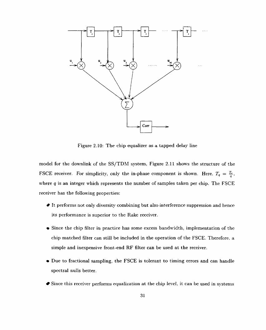
Figure 2.10: The chip equalizer as a tapped delay line
moclel for the downlink of the SS/TDbI system. Figure 2.11 shows the structure of the
FSCE receiwr. For sirnplicity. only tlie in-phase component is sliown. Here. T, = - < I '
where q is an integer which represents the number of samples taken per chip. The FSCE
receiver has the following properties:
It performs not on1y diversity combining but also interference suppression and hence
its pcrformancc is supcrior to the Rakc rcccivcr.
Since the chip filter in practice has some escess bandwidth, implemeiitation of the
chip matched filter c m still be included in the operation of the FSCE. Tlierefore. a
simple and inespensive front-end RF filter can be used a t the receiver.
r Due to fractional sampling, the FSCE is tolerant to timing errors and can handle
spectral nulls better.
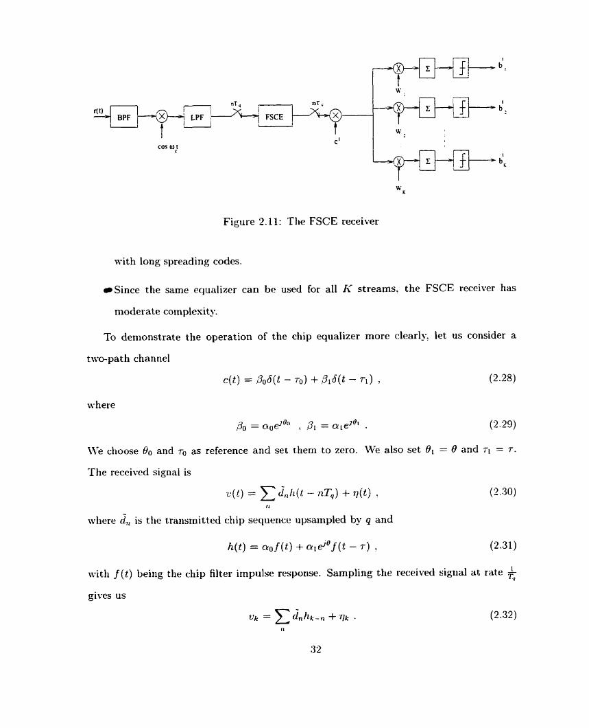
Sirice tliis receiwr perforiiis equalizatioii a t tlie cliip level, it cari be used in SJ-st,eiiis
31
I cos W l
Figure 2.11: The FSCE receiver
with long syreading codes.
Since the same equalizer can bc used for al1 h' streams, the FSCE receiver has
moderate coinplesity.
To demonstrate the operation of the chip equalizer more clearly, let us consider a
two-pat h channel
We choose 00 and ro as reference and set tliem to zero. We also set BI = 0 and ri = T .
The received signal is
- wliere d , is tlle trarisniitted diip sequeiice upsarnpled by q arid
h( t ) = no f ( t ) + oid0 f ( t - T ) y (2.31)
with f ( t ) ùeiiig the cliip filter impulse resporise. Sampling the received sigiial at rate '- r,
gives us

Based on (2.31), t he folded spectrum of h ( t ) is
where F ( w ) is the Fourier Transform of f (t). The chip equalizer will t ry t o equalize
HTq ( w ) If tve assume that sampling rate is liigh enough, we can focus our attention on
the interval [-- "1. In this interva1 we have TV
According to (2.23). the periodic transfer filnction of the hIMSE eqiializer will he
f o r - L < w c z . =, TP sin(?)
For esample, for f (t) = +, - i.e. a sinc pulse with zero escess bandwidth? we have 'rc
and
- Tc f o r l w l < $ F ( w ) =
O othernrise
Thus, (2.34) and (2.35) become
T c - HTq (w) = [ao + a l ej("-ur)] - for Iwl < 5 . Tq
For other cliannel profiles, a simiiar approach can be taken. \fi now use (2.37) t o
plot I ~ ~ ( w ) l * for different values of r and B. For simplicit- we assume Tc = 1 and
CLO = QI = fi . Figures 2.12 and 2.13 show I H ~ ~ ( w ) ~ ~ for different values of 0 witli
i = Tc aiid T = f Tc . respect ively.

Figure 2.12: Plot of 1 HT, (LI)/' for r = Tc
Figure 2.13: Plot of 1 HT, (w ) l2 for r = f Tc

ive observe that when T c 'Ti, the received signal energy is dependent on O and varies
significantly as O changes (flat fading). From (2.37). it can be observed that when r 2 Tc:
IHT,(w)l2 takes al1 the values betneen (aa - and (ao + a l ) 2 inclusive. This means
that the received signal energy is fixed and does not depend on the value for 8 (frequency-
selective fading). In this case? it can be seen that regardless of the value of 0: the channel
has a spectral nul1 if a. i a, (see Figure 3.12). To compensate for t hist the linear equalizer
has to put a large gain a t the frequency where the nul1 occurs. This in general results in
noise enhancement. A Decision-Feedback Equalizer (DFE) would fix this problern [25].
However, since ive are performing equalization on chips not bits, a DFE cannot be used in
this case because the ctiip values are uriknowri to the receiver. While bits cari take either
+l or -1 (in case of BPSK), the overall chip sequence has values between -K and +I<
and lience is more difFicult to estimate. In the case of IC = 1: chip values are either +I or
-1. Therefore, simple chip detection can be done and the resulting decisions can be fed
back. Homever, because chip detection does not bencfit from the processing gain. chip
decisions would not be accurate and hence the performance of the DFE would be poor.
2.5 Chapter Summary
In this chapter, we described the SS/TDRI transmission scheme as a prornising candidate
for the downlink of packet-based systems. We studied the conventional Rake receiver and
mcntioricd its limitations. 14.c thcn prcscntcd a novcl rcccivcr bascd on chip cqualization
n-liich is particularly siiitablc for the downlink of the SS/TDhI systcm. WC also dcscribcd
some of the advantages of this receiver as compared to the conventional Rake receiver. In
the following chapter, we will perform a n estensiw stiidy of the performance of the de-
scribed FSCE receiver using a series of detailed simulations and compare the performance
with that of the Rake receiver.

Chapter 3
Simulation Results for the FSCE
Receiver
In the previous chapter, tve presented a receiver for the downlink of SS/TDh,I systeins
based on chip equalization. We claimed that this receiver tvould outperforrn t,he con-
ventional Rake receiver whosc performance is interference-limited. Since the downIink
transmission is synchronoiis, if we use orthogonal spreading codes, intracell interference
can be avoided provided t hat t, he orthogonality among the spreading codes is maint ained.
But, a multipath channel will destroy this orthogonality and, hence, will cause interpath
and interchannel interference. ,A Rake receiver will perform poorly in sucli a system. How-
ever? channel equalizat.ion can restore the orthogonality and eliminate the interference.
This \vil1 considerably improve the performance of the receiver.
.Ilthough channel equalization for the dotvnlink of CDM-4 systems bas been proposed
in [1G]-[19]. the performance of such a receiver has not been discussed in detail. In
this chapter, we present an adaptive implementation of the Fractionally Spacecl Chip
Equalizer (FSCE) receiver described in Chapter 2 for the dotvnlink of SS/TDhI systems.
In addition, we study, in a comprehensive nianner, the effect of various system parameters
such as processing gain, channel profile and constellation size on the perforinance of the

FSCE receiver using a series of detailed sirnulations. Our simulation results provide insiglit
into the design of the downlink receiver for future high bit-rate SS/TDhI systerns.
3.1 Simulation Mode1 and Assumptions
In this section, ive give a detaited descriptiori of the mode1 used in our simulations and
state the assumptions made. -As we mentioned in the pre\-ious chapter. in a SS/TDM
system, time is divided into slots (frames) of length q, During each time slot' the base
station transmit data t o only one user using spread spectrum transmission. The data bits
of the user are divided into K streams. These streams are spread using orthogonal Walsh
codes and are then summed together. The overall sequence is multiplied by a P N code
unique to the base station. The resulting sequence goes through a chip filter and is tlien
transmitted.
The received signal is the surri of scaled, delayeci versioris of t lie t rarisrrii tt,ed sequerice
plus noise. The receiver corisists of a front-erid filter followed by a Fractiorially Spaced
Chip Equalizer (FSCE). The output of the equalizer is then multiplied by the P N and
Walsh codes and is summed over one symbol period. The result is sent to a decision
device (threshold detector) to get t,he data bits. Throughout this chapter, we assume
one transmit and one receive antenna. Mé do not consider sectorization. In our simula-
tions, ive mode1 the background noise and intercell interference as white Gaussian random
variables.
M.'c considcr a SS/TD-LI system with bandwidtli of B = 1 .25AfHz as uscd in 1s-95.
We assume that each time slot is 1.432ms long, i.e. Tj , = 1.432ms. From tliis 1.432mn.
ive a1locat.e 9%, which is eqiial to 130p,.s, to the pilot. The radio channel is assiimed to he
time-invariant duriiig each frame. This is a reasonable assumption because for a mobile
nioving a t a speed of 1001iPm/h, the coherence time of the channel, rCoh, is about 5.3ms
at 2GHz . This means tliat Tj, is about 4 times smaller than T ~ ~ , ~ . Hence, it is safe to

assume that the channel does not change during one frame.
The downlink radio channel is modeled as sum of L muitipath components. This can
be represented in baseband as
The amplitude of each component., al, is assumed to be a Rayleigh random variable.
The phase, &, is iiniformly distributed between O and 27;. The delay of each path. 71.
is assurned to be fised. ,As we mentioned above, throughout our simulations, we always
assume block fading. It ineans that a L 7 s and 81's stay constant during one frame. From
one frame to another, ive assume independent fading. The channel multipath components
are also assumed to fade independently.
-4s we change the processing gain, the frame Iength is kept the same (i.e. TI, =
1.432n~s). So, if the processing gain increases. siiice the chip rate is fixed, the nurnber
of syrnbols in each fraine decreases and vice teersa. To give an esample. if ive choose a
processing gain of 16. 1.e. = 16, the number of symbols in one fraine will be 110. Out
of the 110 syrribols, 10 syrribols d l be for the pilot. arid 100 syrnbols for the actual data.
If ive diange the processing gain to 4, each franie will have 440 synibols, 40 for tlie pilot
and 400 for data. This way the duration of the pilot burst and the data cornponent of
each frame stays the same independent of the processiiig gain. It should also be noted
ttiat Ive assignecl 9% of each frame to training SJ-mbols. This percentage can be reducecl
by increasing the nurnber of data symbols i r i the frarne as long as the frame duration stays
sufficiently small (i.e. TI, < T ~ , ~ ) .
In our simulations. ive consider both in-phasc (1) and quadrature (Q) channcls. Thc
same set of Walsh codcs is uscd for both channcls. Honrcvcr, the P N codes for the channcls
are different. We assume that the P N codes have long periods and hence mode1 them as
two random sequences. The overall chip secluence. dLQ7 is a complex sequence. Its real
part. d!,' is the in-phase sequence and t h e imaginary part, dnl is the quadratiire sequence.

For the transmitter chip filter, f (t), we use a square-root raised-cosine pulse [31] with
a roll-off factor of a = 0.01725 sirnilar to IS-95. Since our receiver uses a fractionally
spaced chip equalizer, the receiver chip filter: g ( t ) , does not have to be matched to the
transmitt.er filter, However, in our simulations: Ive assume that g ( t ) is also a square-root
raised-cosine filter. We combine the transmitter and receiver chip filters with the impulse
response of the channel to get
L- I
1=0
where p ( t ) = f ( t ) * g ( t ) is a raised-cosine with a roll-off factor of a. = 0.01725, i.e.
Since h ( t ) is unlimited in time domain, we truncate it to get
where ~,,,, and Tupper are the lower and upper limits of truncation. respectively. Through-
out our simulations. the time spans of the chip fiIters are chosen to be 6Tc. Xlso. we choose
the first path of the channel as the reference and set its d e l q and phase to zero, i.e. TO = O
and O0 = 0.
The discrete ciiannel (plus chip filters), h = [h,]? is obtained b j ~ sampling h( t ) : i.e.
nhere T, = 5 and q, which represents the ~iurnber of samples taken per chip, is a positive
integer. Since we are using a fractionally spacecl equalizer a t the receiver, the transmitted
cliip sequence, cl?. is upsampled by q to get diQ. This sequence is tlien convolved witli
. Soise, rlnQ. is added to get r, , . It should be noted that srQ consists of two inde-
pendent noise components and @ each with variance 02. The FSCE is represented
b~ an FIR filter, u: of Iength AI plus a downsampler. Since t,he transmitted chip values
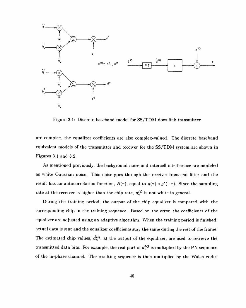
Figure 3.1: Discrete baseband mode1 for SS/TDhI downlink transmitter
are coniples, the equalizer coefficients are also cornplex-valued. The discrete baseband
cquivalcnt rnodcls of the transmittcr and rcccivcr for thc SS/TDRI systcrn arc shown in
Figures 3.1 and 3.2.
As mentioned previoiisly, the background noise and intercell interference are modeled
as white Gaussian noise. This noise goes through the receiver front-end filter and the
result has a n autocorrelation fiinction, R ( r ) , equai to g ( r ) * g* ( - T ) . Since the sampling
rate a t the receimr is higher than the chip rate, vLQ is not white in general.
Diiring the training period, the output of the chip eqiializer is compared with the
corrcsponciing cliip in the training secluence. Based on the error. the coefficients of the
equalizer are adjusted using an adaptive algorithm. When the training period is finished,
actual data is sent and the equalizer coefficients stay the same during the rest of the frame.
The estimated chip values? dfP, at the output of the equalizer, are used to retriem the
transmitted data bits. For example, the real part of dnq is multiplieci by the PN sequence
of the in-phase channel. The resulting sequence is then miiltiplied by the Walsh codes

Figure 3.2: Discrete baseband mode1 for SS/TDM domnlink with FSCE receiwr
and summed over IV samples.
The signal to noise ratio (SNR) is defined as the ratio of t.he average signal poiver to
the average noise (background noise plus intercell interference) power. The noise power
is normalized by the processing gain t o make fair cornparisons between the cases with
different processing gains. As a measure of SNR: we can use %, where Ea is the average
bit energy and 9 is the twesided noise spectral density.
Since the equalizer used in the receiver is a chip equalizer, tlie training has to also be
done at the chip level. In the SS/TDM system, al1 Ir' Walsh codes are used by the base
station to send data to a single user in each time slot. Therefore, al1 W'alsh codes should
be available at al1 mobile receivers. Mobile users also have knowledge of the PIN code used
by the base statiori. Corisequently, seriding knowri bits is equivalerit to seridirig kriowri
chips. If tlie receiver knows the training bits it cari easily generate the corresponding chip
sequence.
Anothcr important point regarding the training sequence is that since the equalizer
acts on chips, the power of the chip sequence during the training period should be equal
t o the p o w r of t.he chip sequence during data transmission. This means that if we are to
use I< streams of bits during data transmission: we should also use Ir' t rainirig st reams or
onc training strcam with I< timcs thc powcr. If thc training chips liavc a diffcrcnt powcr
than the data chips, thc pcrformancc of thc cqualizcr dcgradcs whcia i t is switchcd from
training mode tm data niode. In our simiilations, 1c-e use I< streams of t.rairiing bits.
-4nottier key parameter in training is the achieved level of Mean Square Errnr (MSE).
This deterniines how meIl we can estimate tlie chip values during da ta transmission. -4
good estimate of the chip sequence will ultimately result in good receiver performance.
While n.e are interested in a low SE value, Ive would like to converge to this ~ a l u e as
fast as possible to minimize the amount of overhead in each frame. In other words, we
would like our adaptive algorithm to have fast convergence and achieve low mean square
error. At the same time, we want to keep the coniplesity of t h e algorithm reasonable.
X good candidate for such an algorithm is the Recursive Least Squares (RLS). The RLS
algorithm converges t o a lom MSE value in approxirnately 3.U iterations' where 113 is the
length of the eqiializer [32]. The complexity of the algorit.hm is of the order of 11f2. For
al1 our simulations, ive use RLS algorithm to adapt the equalizer coefficients during the
training period. This algorithm is briefly described in Appendis -4.
To compare the performance of our receiver with that of the conventional Rake re-
ceiver. we will perform a number of simulations for the Rake receiver. In our Rake
simulations. we assume that the sampling rate is one sample per chip. LL'e assurne that
Rake has L fingers where L is the nurnber of multipath components of the channel as
showri by (3.1). The amplitudes? piiases and delays of the rriultipath cliaririel are assurried
to be kriowri to tlie Rake receiver.
For the cernainder of this chapter, we refer t o our proposed FSCE receiver (shown in
Figure 3.2) as chip equalizer although it consists of an equalizer and I< despreaders.
3.2 Simulation Result s and Discussions
We nonr present a series of simulation results in order to study the effect of various
system parameters such as processing gain, channcl profile and constellation size on the
performance of the FSCE receiver. In our simulations. we set the delay between the
transrnittcr ancl the receiver in sucli a way that the ceriter of the eqiializer coincides with
the ccntcr of thc channcl profile (i.c. ccntcr of thc rnultipath). \\'c transmit a t Icast
1000 framcs and continue thc transmission imtil 100 framc crrors occiir. A framc crror
happens when a fi-ame has one or more bit errors. We calculat,e the total ntiniber of bit
errors and di\.itlc i t by the total nimber of transrnitted bits to ohtain the bit, error rate.
Since t hcre is a synimetry between the in-phase and quadrature channels, nre only focus
on the in-phase bit error rate. In calculation of the bit error probability. we only look a t
the receij-ed bits of tlie first Stream.

Figure 3.3: QPSK constellation
3.2.1 QPSK
Hcrc, WC study the rcccivcr performance for QPSK modulation. The constcllation is
shown in Figurc 3.3. In this modulation schcrnc, cach symbol can takc onc of four valucs:
{ + l + j , -1 + jt +l - j . -1 - j ) .
To avoid long description of the channel, wc use the following notation: { ( T , . Pl):
(F-, Pz) , . . . ). Each pair represents one path of the muitipath channel. The first compo-
nent of each pair is the path delay and the second component is the path average power
(in dB) relatil-e to the first path.
FSCE vs Rake
ive first give a comparison between the corwentional Rake receiver and the Fractionally
Spaced Chip Ecpalizer (FSCE). Figures 3.4 and 3.5 show the average bit error rate (BER)
vs $ of tliese two receil-ers for different values of Ii with LV = 4 and N = 16. respeçtively.
The channel is assurnecl to have two paths with equal average powers. The clelay between
the two paths is r = ?Tc. Based on our notation, we can represent this channel as
{ ( O , OdB), (STc, OdB) }. The chip equalizer has 15 taps and uses two samples per chip
(JI = 15. q = 2). -4s a reference, the optimum single-user BER curve for the case of
Rayleigh fading with second order diversity is also shown [25].
-4s espected, the chip equalizer performs significant ly bet ter than Rake especially as
I< increases. It is also seen t h a t the BER curves for the Rake receiver ievel off much

IOO L i i 1 1 I l 1 I I i i 1 b r 4 K=1, FSCE ] -O- K=1, RAKE 1 + X.2. FSCE 11 -x- K=2, RAKE
1 - . optimum 11
Figure 3.4: Coniparisori hctn-een t h e FSCE and Rake receivers (!Y = 4, two-path channel
with 5 = 2Tc: QPSIi;)

U K=1; RAKE * K=4, FSCE -x- K 4 , RAKE + K=8, FSCE a- K=8, RAKE + K=16, FSCE T- K46, RAKE . - . optimum
Figure 3.5: Comparisori betwe~ri the FSCE and Rake receivers ( N = 16: two-path channel
with r = 2Tc1 QPSK)

faster than tliose corresponding to the FSCE. This is because the performance of the
Rake is limited by interpath and interchannel interference. -4s K increases? the amount
of interference increases and the performance of the Rake receiver degrades considerably.
It should be noted that since the FSCE receiver performs equalization at the chip
level, the SNR seen by the equalizer is related to g: where Ec is the chip energ-. In
our SS/TDM system, Ec = 5~~ . The behaviour observed in Figure 3.5 for the case of
Ar = 16 and h' = 1 with the FSCE receiver is because the SNR seen b - the equalizer in
this case is very low and, hence, good convergence cannot be achieved during the training
period.
Effect of Processing Gain
ici Figure 3.6. we corripare the perforrriance of the diip equalizer for two differeilt processirig
gairis (N = 4 arid N = 16). I t sliould be rioted that sirice ive keep the duratiori of the
franies fised independerit of the processing gairi. as we iricrease IV? we tiüve to increase
I< with the same proportion in order to keep the bit rat.e the same. But increasing I<
means increasing the overall transrnitted pomer. So, to keep the comparisori fair! ive
normalize the signal (or noise) power. -1s i t can be seen from Figure 3.6. changing the
proceçsirig gain does not have any significant effect on the performance of the FSCE. This
makes scnsc bccausc the cqualizcr acts on chips not bits. So: FSCE secs no differcncc
bctwccn thc two cas- bccaiisc thc incoming chips look thc samc (proviclcd that tlic poncr
is normrxlized properly). Of murse, the processirig gain cannot. be niatle arbitrarily srrièt l l .
In the cstreme case of ,\i = 1: the whitening efkct of the spread spectruni will totally
disappear.
EfTect of Channel Profile
\Ve now look at the performance of the chip equalizer and the Rake receiver for three
different channel profiles:

1 O-' I 1 I I 1 l I l I I 1 I I
-2 O 2 4 6 8 10 12 14 16 18 20 22 24 26 EdN, (dB)
Figure 3.6: Effect of processing gain, N. on the performance of FSCE (thmpath channel
with T = ZT,, q = 2: hl = 15, QPSK)
1- Channel 1: Two paths with equal average poivers and delays of O and -Tc: i.e.
((0 . OdB), (2Tc , O ù B ) ).
2. Channel 2: Four paths with equal average powers and delays of O. T,: WC, and 3Tc:
i .e. {(O , OdB) , (Tc OdB) , (2Tc . OdB). (3Tc OdB) ).
3. Channel 3: Four paths with decaying average powers and the sarne delays as Channel
2 , i.e. ( ( O - OclB), (Tc . -3dB). (-Tc . -GdB), (3Tc : -9dB)).
Figure 3.7 and Figure 3.5 show the simulation results for the case of lh7 = 4 and F< = 1.
The FSCE has the same tap spacing and length as the previous section, Le. q = 2 and
J I = 15. For the Rake receiver, the two-path channel has the best performance and the
four-path channel with equal average powers has the worst performance. This is because
the channel with four pat hs of equal strengt li causes the largest iriterpat h interference.
The interference caused by the channel with decq ing average powers is srnaller. The two-
path channel introduces the least amotint of interpath interferencc. It should be noted
that although the four-path chaniiels provide 4'" order diversity. the improvement over
the Y d order diversity pro\-ided by tlic tmo-path channel is overshadowed by the extra
interpath interference. For the chip eqtializer, on the other hanci? the four-patli cliannels
perforni bet ter tlian the two-path channel. This is because of the estra diversity provided
by tliese two clianriels. Since tire equalizer is able to suppress the int,erpath interference,
tlie est ra diversit .~ contributes to thc perforrnarice iniprovemerit seen in Figure 3.5.
Effect of Intersymbol Interference (ISI)
Ses t , ive studj- the effect of iiitersyrribol i~iterfere~ice (ISI). caused by a large ctiarinel
d e l v spread, ori tlie perforrriarice of ttic chip equalizer. To do tliis, we corisider a two-
path ctiaririel with a d e l q of GT,. i.e. ( ( O , OdB), (GT,, OdB)}. Figure 3.9 looks a t two
cases: one is the case of iv = 4 which rneans ISI esists. The other case is the case
of :Y = 16 wliicli corresponds to rio ISI. -As i t can be seen frorn the figure. ISI has no

4 Channel 1 (two paths) * Channel 2 (four equal paths)
Figure 3.7: Performance of the Rake reçeiver under tliree different channel profiles (:Y = 4:
K = l ? QPSK)

Figure 3.5: Performance of the FSCE receiver iinclcr three different chanriel profiles ( N =
1 l o O
IO-'
1 o - ~
[21 W m
1 o - ~
IO-^
[ -
1 IO-^. I I I l I I I I I 1 I I I i
-2 O 2 4 6 8 10 12 14 16 18 20 22 24 26 E p J , (dB)
r 1 1 4 1 I I 1 1 L 1 I 1 I + Channel 1 (two paths) * Channel 2 (four equal paths) -6- Channel 3 (four exp paths)
: -
.- -
7 -
= -
r

Figure 3.9: Effect of ISI on the perforiiiance of the FSCE recciver (two-path channei,

significant effect on the FSCE performance provided that the equalizer is long enough to
cover the channel length. The reason for this is that the equalizer processes chips not
bits. The FSCE tries to equalize the chips without any knowledge of the iinderlying bit
patterns. Because of the long PN sequence used to randornize the chips, the case of ISI
(:V = 4) does tiot look any different t o the equalizer than the case of no ISI (3- = 16).
However, as it is shown in Figure 3.9: for the same equalizer length, larger delay spread
results in poorer performance. This, of course, cornes as no surprise because the equalizer
needs rnore taps to equalize a channel with a larger delay spread.
I t is known that 16-Q-fiRI has a higher spectral efficiency ttian QPSK. This is because
each symbol in 16-Q-AM reprêsents 4 bits wliereas in QPSK eacli syrnbol represents 2
bits. Herice, the rriaxirriurri achievable spectral efficiericies for 16-QU1 arid QPSK are 4
and 2 bits per second per Hertz, respectively. Since the radio bandwidth is ver' limited,
to achieve high bit rates, we have to increase the spectral efficiency of our system. One
approach is to try to use a high-order modulation scheme such as 16-Q-4M instead of
QPSIi. This motivates us to study the performance of the FSCE with 16-QAh,I as the
n~odulation scheme. In this section: we present simulation results for 16-QAh,i. In the
following section, WC cornparc thc performance of thc chip cqualizcr for the tmo modulation
sclicri1cs.
Iri 16-Q,\h.I, cadi symbol caii takc one of 16 \*ducs as shown in Figrirc? 3.10. For
oiir simtilations. t,he chip eqiializer is assiimed t o have 15 taps with n spncing of 2 - (Le.
51=1.5. q=2). Figure 3.11 shows the BER rs % for different values of li with N = 4.
The channel in this case has two paths with equal average powers and a delay of LTc-
Thc figure shows siniilar trends as for the QPSII; casc. Howcvcr, in this case? t.hc Rakc
receiver performance is estremely poor dile t o escessive amoiint of interference causeci by

Figure 3.10: 16-Q.AX,I constellation
16-Q-4h.I modulation sclieme.
-4s it is shown in Figurc 3.12. proccssing gain docs not have any signifiant effect on
the pcrformancc of thc cqualizcr. This, as csplaincd prcviously. is duc to thc fact t.hat
the FSCE eqtializes chips not bits. In Figure 3-13: ive compare the cases of 1SI and no
1S1 for 16-Q.414 as ive did for QPSK. Again. here we see that while a largrr delay spreacl
degracies the performance of the eqiializer, the performance is independent of whether ISI
esists or not.
i ve now would like to compare the receiver performance for the cases of QPSK and
16-QXh.1. This will help us decide when to switch the moduiation scheme from QPSIi to
16-QUI and vice versa.
3.2.3 Comparison Between QPSK and 16-QAM
As ive mentioned carlier, 1GQ-UI has a spectral efficiency that is two timcs higlier than
QPSIi. Since spectrum is scarce i r i wireless commuriication, we would like to know when
it is sensible to switch froin QPSK to 16-Q-AlSI. To answer this question, consider the
following scenario:
In our SS/TDhI system, we are transmitting data t o a mobile terminal iising QPSK.
Let us assume tha t we have a processing gain of 4 and we are using 2 IVCilsh codes. i-e.

I I I l i 1 l I 1 I I I I
+ K=l , FSCE : U K=l , RAKE . +- K=2, FSCE -x- K=2. RAKE .
-B- K=4. FSCE . 4- K 4 , RAKE
Figure 3.11 : Coin parison between the FSCE and Rake receivess ( N = 4. two-patli channel
witli 7 = 2T& IG-Q-AhI)

Figure 3.12: Effect of processirig gain, iV, on the performance of the FSCE receiver (two-
path channet with r = 2Tc, q = 2, A l = 15, 16-QXM)

Figure 3.13: Effect of ISI on the performance of the FSCE receiver (two-path channel,
q = 2. A/ = 15, 16-Q-Ah[)

iV = 4' = 2. Now consider that the channel condition improves. With the improved
channel condition. we can transmit more bits without sacrificing the probability of error.
There are two ways t o increase the bit rate. One is to keep the modulation scheme as it
is (Le. QPSK) and increase the number of Walsh codes. -4nother approach is to keep Ii-
the same and instead switch from QPSK to 16-QAM. The question is which method is
more efficient?
Figure 3.14 tries to answer this quest,ion. In this figure we have shown the BER curves
for QPSK and 16-Q,4R3. The dashed iine is the reference curve which corresponds to
QPSK witb N = 4 and = 2. It is seen frorn the figure that for t,he same overail bit
rate, usiiig QPSK is riiore efficient ttiari usirig 16-Q-4bI. For esarriple. to double the bit
rate arid keep the BER a t 4 x 1 0 - ~ , if we use QPSK aiid change Iil frorri 2 to -1: ive iieed
to increase the transmitted power by IdB. On the other hand. if we keep A- a t 2 and
switch to 16-QXhI? ive need to increase the power by about 9dB. This means that QPSK
is about 8dB more efficient than 16-Q.AhI. This can be explained as follows:
In the case of QPSK: when ive double K , we double the average transmitted power.
Howcvcr. whcn WC switch from QPSK to 16-QA-UvI: WC incrcasc thc ai-cragc powcr bi- a
factor of 5 . In othcr words. to kccp thc avcrapc transmittcd powcr tlic same. wc have
to diviclr thc arnplititdc of thc trnnsrnittcd 1 6 - Q U I signal by fi. This gives QPSK a
$ ( = 4 d ~ ) adrantage over 16-QAhI in terms of signal to iriterference power ratio [33]. In
addition. effect of fading is much niore severe on 16-QAhl tlian on QPSK [34].
Bascd on thc abovc discussion. switching from QPSK to 16-QUI makcs scnsc only
mhcn WC have rcaclicd thc maxiinum spcctral cfficicncy achicvablc bj. QPSK (i.c. h- = iV).
This means that 16-Q-4hl slioiild be used only after we have reached the 2 bps/Hz ~p~ic t ï i l l
cfficiency possible with QPSK. At this point if we still want to increase the bit rate. \ire
cannot do it with QPSK and ive have to switch to a liighcr order modulation.

1 J I 1 1 1 I 1 L , I i 1 l
4 N=4, K=4. QPSK + N=4, K=2, 16-QAM 1
1 - - N=4. K=2, QPSK (Ref.) I f
Figure 3.14: Cornparison t~etween QPSK and 16-Q-AM (two-path channel with T = lTc,

3.2.4 Correlated Fading
In ordcr to motivatc the antcnna diversity schcmc introduccd in the ncst chaptcr. WC show
the pcrformancc of thc FSCE for a channel with vcry short dclay spread (i.c. smallcr than
onc chip) and cornparc it with that of a channcl with a longer del- sprcad. To do this. WC
consider two channels: one is a two-path channel with eqiial path strengths and dehy of
O.lTc. The other is a two-path channel with eqiial path strengths and delay of 1.1 Tc. The
FSCE has 1.5 taps and a t ap spacing of i.e. AI = 15. q = 2. Figure 3.15 shows the BER
curves for these two channels. From the figure, it is observed that the BER is higher in
the case of short delay spread. This is because a delay of O.lTc results in a high correlation
between the two paths at the receiver. This will reduce the diversity gain significantly.
_At high SNR levels. the effect of diversity becomes more pronounced and the gap between
the two BER curves widens. It should be noted that although the difference betweeii the
average probabilities of error shown in the figure may not be considered significant, the
fluctuation around the average BER value is rnuch larger in the case of the channel with
0. lTc delay spread.
3.2.5 Decision-Feed back Equalizer
We mentioned in the previous chapter that a multipath channel can have spectral nulls. I t
is known that a linear equalizer results in noise enhancement when the channel spectrum
has nulls. To rectify this problem a Decision-Feedback Equalizer (DFE) can be iised [25].
However: since we are implementing a chip equalizer, using a DFE is not feasible because
the chip values are not known to the receiver. However, just to demonstrate the effect of
iising a DFE instead of a linear equalizer we perform the followirig simulation:
We assume a two-patii channel with equal path strengths and delay of WC. We ilse one
data streani. i.e. II' = 1. This way the in-phase and quadrature chip values can be either
+l or -1. We compare the performance of the receiver for tliree cases: a linear FSCE

Figure 3-15: Effect of correlateci fading (two-path ctiannel? N = 1. li = 1 , q = 2: dl = 15)
with q = 2 and 11.1 = 15, a DFE with perfect knowledge of chip values (ideal DFE)? and
a decision-directed DFE. Both DFE equalizers have a feedforward lengt,h of 11 taps and
a feedback length of 4 taps. In ideal DFE? we assume that we have perfect knowledge of
chip values a t the receiver. For the decision-directed DFE, Ive use two threshold detectors
to detect the in-phase and quadrature compone~its of th2 chips before feeding them back
into the equalizer. The simulation results are shown in Figure 3.16. -4s espected the
ideal DFE outperforms the other two. The performance of the decision-directed DFE
is worse than the linear equalizer for low SNR values. This is because chip detection
does ilot benefit frorn the processing gaiii. Hence, the resulting chip decisions are not
accurate whe~i the SNR is not high. At high SNR levels. the decision-directed DFE starts
to outperform the linear FSCE equalizer.
3.3 Chapter Summary
I n this diapter, ive presented a compreherisive study of the performance of the FSCE
receiver for the downlink of SS/TDM systerns. i v e used chiplevel simulations to show
the effect of different parameters on the performance of the equalizer. It \vas çhown that
processing gain and ISI do not have significant effects on the FSCE performance. We
also investigated the performance of the chip equalizer under different channel profiles.
In addition, we cornpared the performance of the FSCE receiver for QPSK and 16-Q.Ah4
modulation scherncs. WC concludcd that QPSK shouki be iiscd instcad of 16-4.-1'11 until
wc rcach the maximum spcctral cficicncy uchicvablc by QPSK (i.e. 2 bps/Hz). \\iC
also demonstrated t.he effect of correlated fading on the performance of the eqiializer.
It was observed that becaiise correlatecl fading rediices the diversity gain: it resiilts in
degradation in performance. In the nest cliapter, we combine transmit antenna diversity
with chip equalization to mitigate this problem.
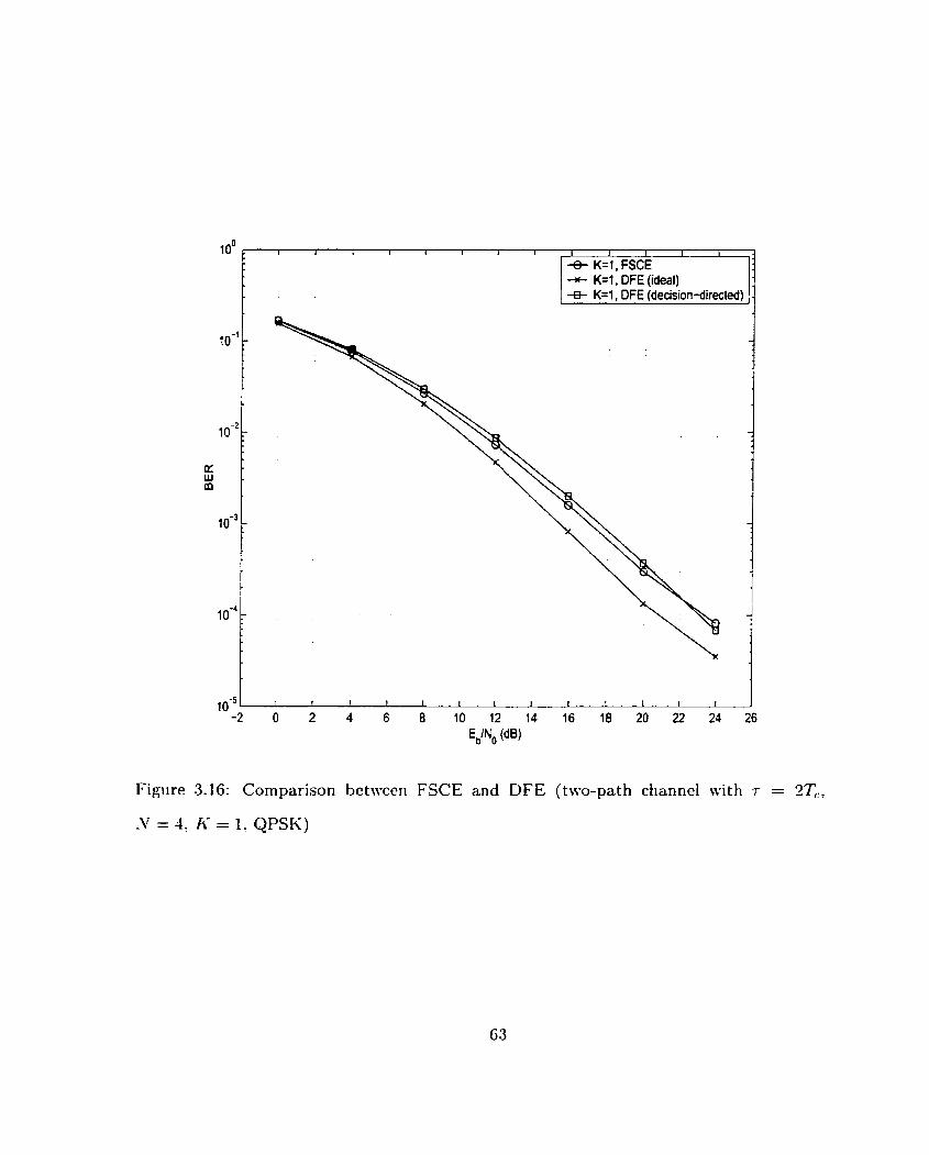
loO r 1 1 4 1 1 I 1 I t L I I l
4 K=l , FSCE -N- K=1, DFE (ideal) -e- K=1, DFE (decision-direct&) 1
Figure 3.16: Cornparison betweeii FSCE and DFE (two-path cfianncl witli r = -Tc,
= 4, A- = 1: QPSIi)

Chapter 4
Combined Transmit Antenna
Diversity and Chip Equalization
Alultipath fading makes reliable wireless communications very difficult . .At the receiver,
multiple copies of the transrnitted signal are superimposecl. This superposition could he
constructive or destructive depending on the relative phase of the multipath components.
Destructive superposition results in deep fades in the signal amplitude. This, in turn, will
cause error bursts in the received bits. To combat fading. diversity techniques arc used.
In a11 of these techniques. multiple copies of the signal are sent in such a way tha.t these
copies undergo independent fading. This way? the probability t hat al1 of them fade at the
same time is reduced considerably.
-4s we nlentioned in the previous chapters, spread spectrum provicles pat h di\-ersity
if the bandwidth of the signal is larger ttian the coherence bandwidth of the channel
(frequency-selective fading). On the other hand, in environments siich as indoors where
the clelay spread is short. al1 multipath components ma- arrive within one chip period (flat
fading). In this case, the energy of the received signal fluctuates considerably depending
on tlie relative phase of the multipath components. One approach for mitigating the
flat fading problem is t o spreacl the signal over a larger bandwidth such that the fading
becomes frequency-selective. However, in many cases, this solution may not be practical.
For esample, to achieve frequency-selective fading: it may be required t o spread the signal
over a bandwidth larger than the allocated bandwidth for the syst.em. Even if we have the
freedom of increasing the system bandwidth, it mal- require costly hardware modifications.
-An alternative approach is to use other sources of diversity to mitigate fading. It should
be noted that even in the case of frequency-selective fading: in many real-life scenarios,
there is a strong correlation between adjacent resolvable multipath components [35]. This
means that even in frequency-selective channels, t here may still be a need for additional
sources of diversity.
,\riterina diversity is an effective way to combat fading. Due to size and conipiexity
limitations of the mobile terrriinal, placing multiple aritennas a t the mobile is not very
practical. -4s a result, for the downlink, transmit diversity is preferred over receive diver-
situ. Alost transmit diversity methods are either bandwidt,h inefficient or require feedback.
Alamouti in [4] and DaSilva and Sousa in [5] have proposed two different transmit diversity
techniques for flat fading channels. A1amout.i uses a special case of orthogonal space-time
coding (361 to achim-c divcrsity whcrcas DaSilva and Sousa rotatc the constellation to
obtain rcsistancc against fading. Both mcthods arc bandwidth efficient and do not rc-
qiiirr fccdback. A modificd version of Alamouti's schcmc lias becn proposcd in [ï] for ISI
channcls and narrowband niodiilation.
In this &aptes: we first clescrihe Alamoiiti's diversity schenie for flat fading channels.
After that. we apply t h e modified version of this schenic proposed in [î] to spread spectriirii
ancl combine it with chip equalization to achieve both di\;ersity gain and interference
suppression in channels with short delay spread. At the end, we show simulation results
for the combined scheme.
4.1 Alamouti's Diversity Scheme
In [Il. .-\lamouti presented a two-branch transmit diversity scherne for channels with no
intersyrnbol interference (ISI). This scheme uses two antennas at the transmitter and one
antenna at the receiver and achieves the same diversity gain as maximal ratio combining
(MRC) with one transmit antenna and two receive antennas. Furtherrnore, this scheme,
while simple to implemeat, does not require ariy bandnidth expansion and feedback from
the receiver to the transmitter. Here, we give a brief surnmary of .~lamouti 's transmit
diversity scheme.
Let us assume that ure have two antennas a t the transmitter. tVe cal1 the antennas A
and B. At a given symbol period, T l , two indeperident symbols are transmitted sirnulta-
neously froni the two antennas, d.4 from -4ntenna -4 and dB froni Antenna B. During the
nest synibol period! T2, we transmit -d, from -4ntenna .4 and d i from Antenna B. So,
the received signals during Tl and S2 are
and
respectivcly. 111 tlie above equatioiis, ha-\ = ry.4ej0'\ aiid hs = uee~'n regreserit the cfiariiiels
frorn .4riteriria -4 and Aritenria B to the receive aiitenna. d', arid d, are the corriples
coiijugates ~ f ' t l . ~ arid d B , respectively. Iri additiori. 711 arid na are ttic additive rioise wtrich
is assiimed to bc white and Gaussian.
A A Let x 1 = 1-1 and x2 = r.5. Now, (-4.1) and (4.2) can be written in matris forni as

.= [n:]
and
To retrieve the transmitteci symbols. we combine rl and r2 as follotvs
and
d B = h é r , - h,ir; .
After a few simple steps, the above equations become
4 4 = (a2! + a;) d.4 + qi ,
and
whcre i l l ancl are white Gaussian noise. Combining rl and r2 according to (4.4) and (4.5)
is equivalent to niultiplying x by the transpose conjugate of H. Sincc H is an orthogonal
matris, rnultiplying H witli its transpose conjugate resiilts iii a diagonal matris. Hence,
ive Cali ret rieve d.
Equatio~is (4.6) arid (4.7) are similar to the m e s obtairied usirig hIRC witti oiie trans-
mit antenna and two receive antennas. Figure 4.1 shows the transmitter and receiver
for -Ll1amoutits diversity method. The above scheme assumes that the chaniiel does not
67

TI:
Figure 4.1: Transmit ter and receiver structures for -41amouti7s diversity scheme
cause any ISI. In addition? the channel is assurned to be known to the receiver and to be
invariant during Ti and TL. In this scheme: two antennas transmit independent symbols
during Tl. Herice, there is no bandwidth expansion.
4.2 Transmit Antenna Diversity with Chip Equaliza-
tion for SS/TDM Systems
In the previous section. te describecl Alamoutios transmit diversity scheme. \F'e saw tliat
this scheme does not result in bandwidth expansion and does not require any feedback. It
also fits wry m l 1 with the time-division nature of the SS/TDM system. In this section.
ive apply a inodificd version of Alamouti's scherne to the downlink of SS/TDh,I systems
and combine it with the Fractionally Spaced Chip Equalizer (FSCE) receiver proposed in
the previous chapters.
Consider the SS/TDM scheme ive described in Chapter 2 for the downlink of a data-
oriented wireless system. In this scheme, we divide the time into frames. During each
frame, Ive transmit to onIy one user using spread spectrum with orthogonal W'alsh codes.
The channel can be rnodeled as
whcrc 4 = criejol is thc complcs channcl coefficient corrcsponding to thc Ph path and T[
is the corresponding path delay. If the channel is frequency-selective? a Rake receiver c m
be iised to esploit thc path diversity. In Chapter 2, we claimed that an FSCE rcceiver
not only exploits this diversity but also cancels interpath ancl interchannel interference
and hence is superior in performance to the Rake receiver. Our simulations in Chapter 3
confirmed tliis claim. In addition: we showed that if the relative path delays are smaller
than one chip period, the performance of the FSCE receiver degrades because of correlated
fading. Our goal in this section is to combine chip equalization with transmit cliversity.
This will not only kecp the advantages that the chip equalizer had over the conventional
Rake receiver but also provide additional diversity for combating fading.
We use two antennas at the transmitter (base station) and one antenna at the rccei~ver
(mobile terminal). The transmit antenrias are placed far enough so tliat thcir signals
undergo independent fading. After the data symbols are divided into i< streams? they are
spread using orthogonal 1Valsh codes. The resulting Ii- seyuences are summcd together
and are multiplied by a scrambling code. The resuiting comples-valueci cliip sequcnce is
clfQ(rz) as descrihed in Chapter 3. The job of the FSCE at the receiwr is to estimate the
transmitted chip sequence. The estimated chip sequence at the output of the equalizer
can then be despread to retrieve the corresponding data bits. Let us for noir- ignore the
spi-eading and despreading operations at the traiismit.ter and receiver. By cloirig so. oilr
system can be viewed a s a non-spread-spectrum system in which transmitted symbols
are chip values (d1Q 's) and the channel has ISI. However: ISI in oiir case is actually
interchip interference (ICI). For the rest of the section. we concentrate on transmission of
chips (instead of bits) but i t is understood that a chip sequence is sum of K data streams
spread by orthogonal codes. Also. for simplicity, we drop the IQ superscript keeping in
rnind that the cliip values are complex in general. tVe now follow a procedure similar to
the one descri bed in [il. We divide each frame into two halves. In the first half, we transmit d,\ (n) from the first
antenna and de(*rt) froni the second antenna, where da4(n) and dB(n) are two independent
chip sequerices. The resultirig received sequence will be
wliere hdl(n) ancl h,*(n) are the cliscrete miiltipath channels from the first and second
transmit antennas to the receive antenna. They are obtained in the same \vit? that
h(n) was obtâined in Section 3.1. In the second half of the frarne, Ive transmit negative
conjugate of dB(n) in reverse order, i.e. -dB(-n) , from the first antenna and con.jugate of
d,l (n) in reverse orde- i-e. df, ( - n ) , from the second antenna. The corresporiding receiveci
sequence is
In above equations. and q2 are Gaussian noise. It should be noted that because we use
a sampling rate higher than the chip rate. and 772 are not white in general.
Let xi (n ) r l (n) and x2(n) r; (-n). This rneans tha t ~ ~ ( 7 2 ) is the reverse-ordcred
conjugate of ~ ( 7 2 ) . At the receiver we combine xl (n) and x2(n) as follows
and

The combining operation can be viewed as a Multiple Input Multiple Output (klIMO)
system where the inputs are xl(n) and ~ ( n ) and the 0utput.s are y,(n) and yB(n) . We
take the z-transform of (4.11) and (4.12) to get
and
We now combine (4.13) and (4.14) with the 2-transforms of (4.9) and (4.10): making use
of the facts that ,Y1 ( 2 ) = Ri ( 2 ) and X2(z) = R;(&), to obtain
ivhere Da-,(,.) and D B ( z ) are the z-transforms of d 4 n ) and d ~ ( n ) : respectively. Further-
more:
Ici (4.15) arid (4. l û ) , rA (2) arid r B ( z ) are z-transforrns of yA(n) aiid yB(r1) wllidi are liiiear
combinations of q1 and q 2 and hence are Gaussian. The abow equations can equivalentlx
New: if we pass y.., (T L ) anci y B ( n ) ttirough two chip equalizers, we can obtain est i~iiates
of claA1 (TL) and dB(n) as sfiow~i in Figure 4.3. The z-tra~isforrri of the MMSE chip equalizer

1 MIMO
r X 1 1 - ?i 2
z-
Figure 4.2: Block diagram of the receiver for the combined çcheme
d iere S,(z) is the power spectrurn of -,,\(n) and ys(n). But Qls(&) = Q - i B ( ~ ) . There-
chip equalizer
y~ d
= chip equalizer . B >
fore,
A >
X 2 > '
r 2 )
The operation of chip ecpalization can be included as part of the MI110 filters. This
rime reverse and conjugale
will give us four filters:
and
Based on above equations, the overall receiver including diversity cornbining and chip
cqualization c m bc writtcn as

Figure 4.3: The overall receiver for the combined transmit diversity and chip equalization
scheme
and
where u ~ ~ . ~ ( n ) , waii(n), wiB(n) and wpB(n) are four FIR filters as shown in Figure 4.3.
IVe can represent these filters in vector form as W ~ A . w p ~ ? W ~ B and W ~ B . In (4.27)
and (4.28), da4 (n) and d B (n) are estimates of the transmitted chip sequences. These chip
sequences are then despread to retrieve the corresponding data bits.
-4s s!iown in Figure 4.3, w l ~ and W ~ A can be concatenated to make a larger filter,
WA. Similarly, w . 1 ~ and w z ~ can be put together to make a larger filter. WB. NOW, W A
and WB can be irnplemented as two Fractionally Spaced Chip Equalizers (FSCE). They
perform cliip matched filtering, path and space diversity combining as well as interference
suppressiori. It slioiild be rloted that based ori (4.18) f 4.20) : the equivalerit cliaririel for
these equalizers has a ierigth wfiich is approsirnately equal to 1riax(2L.~, 2LB) . wliere L,\
and L are lengt hs of he4 ( r r ) arid ilB (n), respectively. This means that to achieve the
same level of interference suppression, w~ and WB must have a larger length compared
to an equalizer used in the case of no transmit diversity. While this increases the receiver
cornplesity. the corribined scheme provides robustness against fading even when the chan-
ne1 delay spread is short. Simple chip ecpalization will not have this robiistness if the
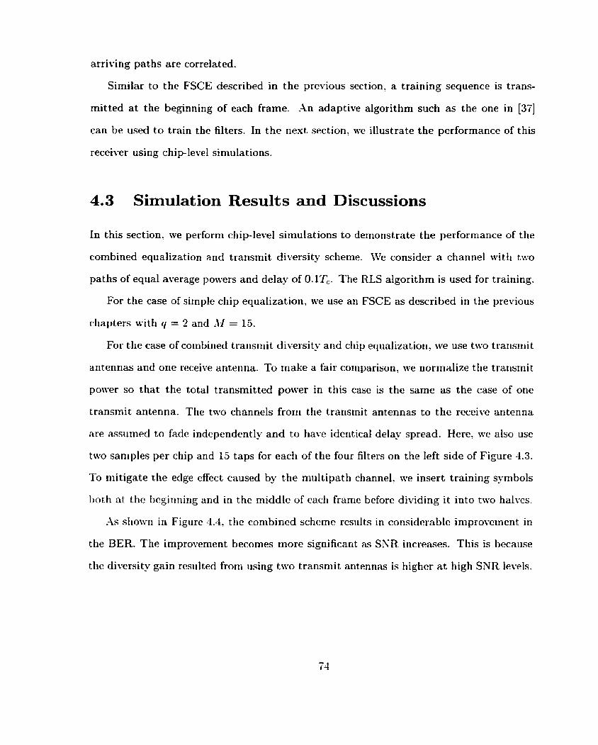
arriving paths are correlated.
Similar to the FSCE described in the previous section, a training sequence is trans-
mitted a t the beginning of each frame. .ln adaptive algorithm such as the one in [XI
can be used to train the filters. In the next section, ive illustrate the performance of this
receiver using chiplevel simulations.
4.3 Simulation Results and Discussions
In this section. ive perform chip-level simulations to demonstrate the performance of the
combined equalization and transmit diversity scheme. Ive consider a channel with two
paths of equal average powers and delay of O.lTc- The RLS algorithm is used for training.
For the case of simple chip equalization. Ive use an FSCE as described in the previous
cliapters with q = 2 and -11 = 15.
For the case of cotribiried trarisrriit diversity arid ctiip equalizatiori, ive use two trarisriiit
anterinas and orle receive ariterina. To rriake a fair cornparisori, we norrnaiize tlie transmit
power so that the total transmitted power in this case is the same as the case of one
transmit antenna. The two channels froni the transmit antennas to the receive antenna
are assumed to fade independently and to have identical delay spread. Here, we also use
two sarriples per chip and 15 taps for each of the four filters on the left side of Figure 4.3.
To initigate the eclge effect caused by the miiltipath channel, we insert training syrnbols
bot11 at thc bcginning and in the middlc of each framc bcforo dividing it into two halves.
-4s shown in Figiirc 4.4, tiic combincd schcinc rcsrilts in considcrablc improvciiicnt in
the BER. The improvement becomes rnore significarit as SKR increases. This is because
tlie diversitu gain rcsiiltcd froni iising two transmit antennas is highcr at high SNR levels.

l o O I l 4 1 1 I I I 1 I - 1 1 I
f + equalization oniy '
- * combined scheme
Figure 4.4: Cornparison between simple equalization and combinecl chip equalizstion witli
transmit diversity (two-patli channel with r = O.lTc, .V = 4: IC = 1)
-- ILI
4.4 Chapter Summary
Spread spectrum can provide path diversity if the signal bandwidth is larger than the
coherence bandwidth of the channel. On the other hand, if the delay spread of the channel
is less than the chip duration. the arriving paths beconie correlated at the receiver. This
will result in reduction in diversity gain and degradation in performance. The same will
happen in frequency-selective channels if the arriving paths are correlated.
To mitigate this problem: we proposed a scheme for cornbining chip equalization with
transmit antenna diversity for the downlink of SS/TDhI systems. The combined scheme,
while being more cornplex, pro\-ides both interference suppression and robustness against
fading. \Ve used transmit diversity because receive diversity is not very practical for the
downlink due to size limitation of mobile terminais. A modified version of -Alamouti's
cliversity scheme was used because this scheme is bandwidth efficient and does not re-
quire any feeclback. The performarice of the conibined receiver was dernonstrated usiug
sirr~u1atioris.

Chapter 5
Conclusions
In tliis chapter, we summarize the results and discussions presented in the previous c h a p
ters. We also suggest a feu- areas for future research.
5.1 Thesis Summary
The traffic of future wireless systerns ndl be mainly data rather than voice. Since the
cliaracteristics of data traffic are quite different from those of voice traffic, there will be
a need for rietworks that are particularly optimized for data rather than for voice. -4
pro~iiising sclleriie for the air interface of tlie downlink of liigh-speed wireless data systeiiis
is the 11)-brid Spread Spectrurri/Tiirie Division h,lultiples (SS/TDM). 1x1 SS/TDI,l. tiriie
is dividec! irito slots. Duririg eadi tirrie slot, data is serit to orily one user usirig spread
spectruni rnodulatiori. Tlierefore. users receive data i r i biirsts. Tlie tirrie division iiatiire
of SS/TDhl facilitates scheduling of different users with different bit-rate requirements
vith ho ut degrading the system performance. It also allows for the traiismission to be
optiiiiized for the user of interest during each time slot. The spread spectrum nature
of the SS/TDhlI scheme provides robustness against interference and allows a frequency
reusc factor of one to he used.

In this thesis, we described a SS/TDM scheme for the downlink of packet-based wire-
less systems. In this scheme: orthogonal (IValsh) codes are used to spread the data signal.
However. multipath propagation destroys the orthogonaiity and causes intracell interfer-
ence. We proposed a novel receiver for the downlink of SS/TDhI sÿstems. This receiver,
which consists of a Fractionally Spaced Chip EquaIizer (FSCE) and a despreader, was
shown to perform significantly better than the conventionai Rake receiver. The chip
equalizer riot orily performs masimal ratio combining to exploit the path diversity but
also suppresses the intracell interference caused by the multipath channel. The FSCE
receiver has rnoderate coniplexity and can be used in systems with long spreading codes.
The fractiorially spaced equalizer provides robustriess agaiiist timing inaccuracies arid
cari haridle spectral nulls bet ter. In addition, sirice FSCE irriplicitly performs matched
filtering, a simple and inexpensive front-end filter can be used at the receiver.
We presented an adaptive implementation of the FSCE receiver and studied its per-
formance using chipleve: simulations. We investigated the effect of different parameters
such as processing gain. constellation size and channel profile on the performance of this
rccci ver.
If al1 multipath components arrivc a t thc rcccivcr within one chip pcriod. sprcad spcc-
trtim cannot proviclc rohiistncss against fading. Thc silrnc will happcn in a frcqiicncy-
sclcctivc channcl if thcrr! is high corrclation betwccn adjacent rcsolvablc psths. To rniti-
gate t his problern, we proposed a scheme thnt combines transmit antenna diversity with
chip equalizatiori. This combined scheme provides bot h robustness against fading and
inter ference suppression in the downlin k of SS/TDN systems. We presented a n aclap-
tivc i~iiplenientation of sucli a receiver and demonstrated its perforniance using chip-le\-el
simulations.

5.2 Future Work
This work can be estended a t a few fronts:
-4 muitipath channel in general has spectral nulis. I t is known that a nonlinear equal-
izer such as the Decision Feedback Equalizer (DFE) is able to handle spectral nulls better
than a linear equalizer. In the case of chip equalization, we need accurate estimation of
chip values in order for the DFE to work properly. But, chip detection is not easy to do
because of the multi-level nature of chip values and because of the fact that chip detection
does not benefit from the processing gain. -4 rnethod for accurately detecting the cliip
values needs to be developed before a DFE can be used effectively.
Another area for further investigation is equalizer training. Given the structure of
the receiver, one can investigate the effect of different training patterns on the equalizer
perforniaiice. For esample: is it better to use K data streams for training or one data
streani with K times the power? What happens if the power of transmittecl signal is
iricreased duririg training to facilitate convergence:' -4lso: effect of different adaptive
algorit hms on the receiver performance needs to be investigated.
For the conibined chip equalization and transmit diversity scheme, one can study the
effect of different system parameters on the performance of the receiver. For esample. the
effect of processing gain, constellation size and channel profile on the receiver performance
can be investigated. In addition, the case of frequency-selective channels with correlated
fading cari IIC studicrl and cornparcd with the casc of flat fading.

Appendix A
The Recursive Least Squares (RLS)
Algorit hm
Here, we briefly describe the RLS algoritlim used to train the Fractionally Spaced Chip
EquaIizer (FSCE).
Let r = [ r ( 0 ) r(1) ... r ( n - 1) r ( n ) r ( n + 1) ... 1'' be the received signal which is
a noisy version of the convolution between the trarismitted chip sequcnce. d, and the
channel, h. Né denote the signal input to the equalizer during tlie nth iteratioa tq-
xj;';' = [ r ( n ) r ( n - 1 ) ... ~ ( 7 2 - iC[ + 1) IT. ivhere AI is tlie nuniber of equalizer taps. The
equalizer output is lience equal t o
wliere u = [ ir(0) ~ ( 1 ) ... u ( d l - 1) IT is the equalizer coefficients. The error is then
where dnJ is the corresponding chip value in the training sequence. MTe tlien obtain tlie
gain vector? Knl , using

1 KY) = p(n- l j x(n)* ( n ) " p c - ~ ) (n)* "' AI :
,w + x,, 'bl
where O < w < 1 is a weighting factor and P,ll is the estimate of the inverse of the
au tocorrelation matrix of the received signal. l i e now update P.il to get
The equalizer coefficients are also updated using
For initialization. we set do) = O and PEI = $ In[, where III is the AI x AI identity
matris and 6 is a small positive constant.
Bibliography
[l] R. C. Dison, Spread Spectrum Systems wzth Commercial Applications. U'i le-
Interscience, 3rd ed., 1994.
[2] -1- J . kïterbi. C D M 4 : Principles of Spread Spectrum Communication. -Addison-
\Cesley? 1995.
[3] G. R. Cooper and R. IV. Kettleton, "-4 spreacl-spectrum technique for high capacity
mobile communications,'' IEEE Transactions o n Vehicular Technologies. vol. VT-7:
pp. 264 275, Kovember 1978.
[1] S. M. .\lamoiiti. "-4 simple transmit divcrsity technique for wirclcss communicat,ions."
IEEE Journal on Selected .4rens in Conzmunicntiom (,JS,4C), vol. 16, pp. 1451 1458,
October 1998.
[5 ] \.. hl . DaSilva and E. S. Sousa, "Fading-resistant modulation iising several trans-
mitter aritennasl" IEEE Transactions o n Communicationsl vol. 45, pp. 1236-1244.
October 1997.
(61 A. F. Naguib. N. Seshadri, and A. R. Calderbank. "Increasing data rate over wireless
chan~ie l s ,~ IEEE Signal Processing Magazine, vol. 17, pp. 76-92. May 2000.
[7] E. Liridskog arid -4. Paulraj, ".A trarisrriit diversity scherrie for cliaririels witli iritersyrri-
bol interference." Proceedings of the International Conference on Communicat ions
(ICC'OO). pp. 307 31 1 . 2000.

[8] R. Price and P. E. Green, Jr., "A communication technique for multipath channels,"
Proceedings of the IRE. vol. 46, pp. 555-570. 5Iarch 2958.
[9] D. Koulakiotis aiid H. -Aghvanii, "Data detectioii techiques for DS/CDhI;\ mobile
systems: a review?'? IEEE Personal Communications Magazine, vol. 7 , pp. 24 34,
June 2000.
[IO] S. Verdu, Wiiiimiim probability of error for asynchronoiis Gaussian multiple-access
channels," IEEE Transactions on infromation Theonj, vol. 32, pp. 85 96. .January
1986.
[ I l ] A. Klein and P. 13-. Baier, "Linear unbiased data estimation in mobile radio sys-
terris applying CDM -4:'' IEEE Journal on Selected Areas in Communications (JSA C):
vol. I l . pp. 1058-1066: Septenber 1993.
[12] -4. J . Viterbi, "Mry low rate convolut ion codes for maximum t heoretical performance
of spread-spectriim multiple-access channels." IEEE Journal on Selected Areas in
Comrnltnications (JSAC) , vol. 8, pp. 641 649. h4ay 1990.
[13] M. K. Varanasi and B. Aazhang: "Multistage detection in asynchronous Code-
Division hl ultiple -Acccss communications," IEEE Transuctior~s on Comnzuni~ations~
vol. 35. pp. 509-519, -4pril 1990.
[14] U. ~ l a d h o ~ v ancl X I . L. Honig: "kIhlSE interference suppression for direct-scqiicncc
spread-spectrririi CDhI-A." IEEE Transactions on Com~rtunica~io7ts, vol. 13. pp. 3178-
3188. December 1994.
[ l5] P. B. Rnpajic and B. S. Vucetic, ''Adaptive receiver structures for nsynchronous
CDh.1-4 systcms." IEEE Journal on Sclectcd Arcas i n Co~nrnunicntions (JSAC).
vol. 12, pp. 685 69ï1 hlay 1994.

[16] -4. Klein, "Data detection algorithms specially designed for the downlink of
CDM.4 mobile radio systems," Proceedings of the Vehicular Technologg Conference
(IfTC'97), pp. 203-201' 1997.
[lï] C. D. Frank and E. Visotsky. "-4daptive interference suppression for Direct-Sequerice
CDM-4 systems with long spreading codes," Proceedings of the Thirty-sixth Annual
Allerton Conference on Communications, Control and Computing, pp. 41 1 420, 1998.
[18] 1. Ghauri and D. T. h4. Slock, "Linear receivers for the DS-CDiLIA downlink exploit-
ing ort hogonality of spreading sequences," Proceedings of the Thirtg-second d silomar
Conference on Signals: Systems and Cornputers, pp. 650-654. 1998.
[19] K. Hooli, hI. Latva-aho, and M. Juntti: bLRiultiple access interference suppression
with linear chip equalizers in Ct-CDMA downlink receivers," Proceedings of the Global
Telecommunication Conference (Globecom 1991, vol. l a , pp. 467-471. 1999.
[20] hl. Davis' A. Monk. and L. B. blilstein, ''A noise whitening approach to multiple-
access noise reject ion- Part II: Implementat ion issues," IEEE Journal on Selected
Areas in Communications (JSAC), vol. 14? pp. 1488 1499, October 1996.
[2 11 1.1. J . Heikkila, P. Kornulainen, and J. Lilleberg, "Interference suppression in CDXiX
downlink t hrough aclaptive channel equalization," Proceedings of the Vehicular Tech-
nolopy Conference (VTC'N)? pp. 978-982, 1999.
[22] K. Li and H. Liu, "-A new blind receiver for downlink DS-CDRtl-4 con~munications."
IEEE Communications Letters, vol. 3: pp. 193-195, July 1999.
[23] J . S. Lee and L. E. Miller, CDMA Systems Engineering Handbook. Artech House
Publishcrs: 1999.

[24] P. Bender. P. Black. hl. Grob, R. Padovani, N. Sindhushayana, and -4. Viterbi.
"CDMA/HDR: -4 bandwidth-efficient high-speed wireless data service for nomadic
users," IEEE Communications Magazine, vol. 38. pp. 70-77, .July 2000.
[35] J. G. Proakis, Digital Co.rnrnunications. McGraw-Hill, 3rd ed., 1995.
[26] A. V. Oppcnheim and R.. W. Schafer, Discrete-Tirne Signal Processing. Prentice
Hall: 2nd ed., 1999.
[27] R. D. Gitlin and S. B. \ITeieinstein, "Fractionally-Spaced Equalization: An improved
digital transversal equalizer," Bell System Technical Journal, vol. 60, pp. 275-296,
February 1981.
[28] S. U. H. Qureslii arid G. D. Forne3;: Jr., "Performance and properties of a T/2
equalizer," NTC'77 Conference Record, pp. 11: 1/1 - 11: l/9, 1977.
[29] D. Saha and S. Pasupattiy, "Fractional sampling and robust equalization," Journal
of the Franklin Institute. vol. 317, pp. 183-21 1, h r c h 1984.
[30] K. J . Kim, S. Y. Kwon? E. K. Hong, and K. C. CVhang? "Effect of tap spacing
on the performance of Direct-Sequence Spread-Spectrum R-AICE receiver," 1EEE
Transactions on Communications, vol. 48, pp. 1039-1036, .lune '2000.
[31] E. A. Lee aiid D. G. Messerschmitt, Digital Communication. Klunrer -4cademic Pub-
lishers, 3rd ed., 1995.
[32] S. Haykin, Adaptiue Filter Theory. Prentice Hall, 2nd ed., 1991.
[33] L. B. hlilstein and A I . S. Lim, "On the performance of a higher order alphabet size
in CDMA!" IEEE Communications Letters, vol. 1, pp. 9-11? January 1997.

[34] C.-J. Kimo \'.-S. Kim: G.-Y. Jung, and H . 4 . Lee, "BER analysis of Q.UI with MRC
space diversity in Rayleigh fading channel," Proceedings of the Personal, Indoor and
Mobile Radio Communicat ions Conference (PIMRC795), pp. 482-485, 1995.
[35] hd. K . Simon and RI.-S. Alouini, Digital Commuizication ouer Fading Clmnrtels: A
UniJied Approach to Performance Analysis. Wiley-Interscience, 2000.
[36] V. Tarokh, H. Jafarkhani, and A. R. Calderbank. "Space-tinie block codes from
orthogonal designs," IEEE Transactions o n h format ion T h e o q . vol. 45, pp. 14.56
14G7, July 1999.
[3T] A. Maleki-Tehrani, B. Hassibi, and .J. hl. Cioffi. "-4daptit-e equalizat ion of multiple-
input mult iple-output (I\/lIh/IO) frequency selective channels," Proceedings of the
Thirty-third Asi lomar Conference on Signals, Systems and Cornputers, pp. 5-17-551,
1999.