note: riser / distributor pipe should be cut 1/2” below
TRANSCRIPT

MTS 95 System
Inst
alla
tion a
nd
Opera
tion M
anual
REVISION # 4 AREVISION DATE SEPTEMBER 19, 2017
NOTE:
RISER / DISTRIBUTOR PIPE SHOULD BE CUT 1/2” BELOW THE
TOP SURFACE OF THE TANK INSERT.
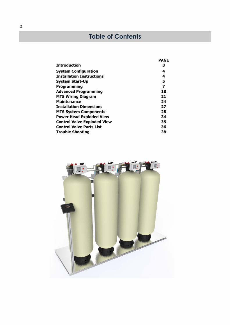
2
PAGE
Introduction 3
System Configuration 4
Installation Instructions 4
System Start-Up 5
Programming 7
Advanced Programming 18
MTS Wiring Diagram 21
Maintenance 24
Installation Dimensions 27
MTS System Components 28
Power Head Exploded View 34
Control Valve Exploded View 35
Control Valve Parts List 36
Trouble Shooting 38
Table of Contents
3
MTS systems have been designed and engi-neered to offer considerable performance ad-vantages compared to traditional products in the Commercial & Light Industrial market to-day.
High Efficiency & High Quality Product Water MTS systems are optimized to use the mini-mum salt and regeneration water necessary to regenerate the system. This reduces wa-ter and salt wasted per regeneration up to 50%.
When used in softener systems during peri-ods of low flow rates, the controller will keep only a single tank in service eliminating the potential for “channeling”. Tanks are brought on or off line according to flow rate demand so that the system is always operating at peak efficiency.
Battery Back Up A battery back up system allows the control-ler to continue metering and tracking water usage for up to 9 hours so that all capacity used during the outage is accounted for.
Track & Forecast Water Usage (NOT AVAILABLE AT THIS TIME) The controller tracks and stores historical us-age and builds a forecast to predict water usage. The controller will automatically in-crease the system capacity to cover peak wa-ter usage periods.
Remote Start An external remote button can easily be added so that the system can be manually started from a control room or other location.
Advanced Diagnostics The system has advanced diagnostics to help trouble shoot any problems that may be en-countered.
Introduction
Standard Features
Polishing Recycle Rinse For softener systems an option for Polishing Recycle Rinse is available. Prior to a tank coming on line product water is recycled through the tank to polish the water and in-sure no hardness is passed to the service line. If the flow rate drops below the point where channeling can occur, the system will also recycle product water to maintain high quality.
Remote Monitoring (NOT AVAILABLE AT THIS TIME) The MTS system can easily connect to a PC directly or wirelessly (3G network) to the internet and to your PC. All system informa-tion and settings can be viewed and moni-tored.
Options

4
1. Locate the system close to a drain where the system will be installed. The surface shouldbe clean and level.
2. Connect the inlet and outlet of the softener using appropriate fittings. Perform all plumb-ing according to local plumbing codes.
Any solder joints near the valve or any other plastic connections must be done before con-necting any piping. Always leave at least 6" (152 mm) between the joints when soldering pipes that are connected. Failure to do this could cause damage.
Installation Instructions
3. Connect 3/4” drain hose to each valve and secure it with a hose clamp. Run the drainhose to the nearest drain pipe. This can be ran up overhead or down along the floor. Ifrunning the drain line more than 20 ft overhead, it is recommended to increase the hosesize to 1”. NEVER MAKE A DIRECT CONNECTION INTO A WASTE DRAIN. A PHYSICALAIR GAP OF AT LEAST 1.5” SHOULD BE USED TO AVOID BACTERIA AND WASTEWATERTRAVELLING BACK THROUGH THE DRAIN LINE INTO THE SYSTEM.
4. Connect the brine tanks to each valve.5. Close the isolation ball valves to each control valve. Open the main bypass ball valve to
the open position. Slowly turn on the main water supply. At the nearest cold treated wa-ter tap nearby open and let water run a few minutes or until the system is free of any airor foreign material resulting from the plumbing work.
6. Make sure there are no leaks in the plumbing system before proceeding. Close the watertap when water runs clean.
7. Open the brine tank salt lid and add water until there is approximately 3" (75 mm) of wa-ter in the tank. Do not add salt to the brine tank at this time.
8. Proceed to start up instructions.Note: The unit is not ready for service until you complete the start-up instruc-tions.
System Configuration
MTS95 Softener System Configuration
Tank Size (Diameter) Injector Set Brine Line Flow Control (BLFC)
Drain Line Flow Control (DLFC)
14" #4S Black
0.9 GPM
#4S (5.0 GPM)
16" #5S Orange/Black Noz #7S (7.0 GPM)
18" #1 Gray #1 (8.0 GPM)
21" #3 Red1.35 GPM
#2 (11.0 GPM)
24" #4White #4 (17.0 GPM)
Suggested Filter Valve Configuration
Tank Size (Diameter) Drain Line Flow Con-
14" #3 (14.0 GPM)
16" #4 (17.0 GPM)
18" #5 (21.0 GPM)
21" #6 (24.0 GPM)
24" none (35.0 GPM)

5
System Start-Up
1. Plug the valves and main controller into an approved power source. 2. Step each valve into the BACKWASH position. Use the UP or Down key to highlight each
tank in the system. Press and hold the SET / REGEN button for 3 seconds to start a man-ual regeneration for that tank.
3. Open the outlet isolation valve on each tank slowly and allow water to enter the unit. Al-low all air to escape from the unit before turning the water on fully then allow water to run to drain for 3-4 minutes or until all media fines are washed out of the tank indicated by clear water in the drain hose.
4. For softener systems, press any button on each slave valve to advance to the BRINE posi-tion. Check the water level in the brine tank to insure the valve is drawing brine properly.
5. Press any button on each slave valve to advance to the RINSE position. Check the drain line flow. Allow the water to run for 3-4 minutes or until the water is clear.
6. For softener systems, press any button on each slave valve to advance to the REFILL po-sition. Check that the valve is filling water into the brine tank. Allow the valve to refill for the full amount of time as displayed on the screen to insure a proper brine solution for the next regeneration.
7. The valve will automatically advance to the SERVICE position when the refill cycle is com-plete.
8. Open the inlet and outlet isolation valves. Close the main bypass valve. 9. Add salt into the brine tanks. 10. Program the system.
Key Pad Configuration
MENU Enter or exit the system menu. Press and hold the button for 3 seconds to unlock the screen.
SET/REGEN Press this button to select a program or to save the settings. Press and hold the button for 3 seconds to initiate a manual regeneration.
DOWN / UP Press these buttons to increase or decrease the value of the settings. Press the buttons to enter the previous or the next menu.
Start-up Instructions

6
System Diagram
Time of Day Number of Units in System
Total System Flow Rate
Remaining System Volume
Percent Capacity Remaining
Unit In Service
Unit Off Line
In regeneration: Back Wash
Time remaining in regeneration cycle
Unit Flow Rate
Unit Address
Optional Polishing Rinse Pump
Optional Polishing Pump Solenoid Valve
MTS 95 SLAVE VALVE 1.25” SS Electric Ball Valve
Isolation Ball Valves System Bypass Ball Valve
2” Inlet
2” Outlet
Main Page Display
Main System Components

7
Programming
Press the MENU button to advance to the first menu page.
Press the UP / DOWN button to highlight and choose the menu. Press the SET button to enter the menu icon you want to edit. The displayed value will begin flashing. Press the UP / DOWN button to adjust the value. Press the SET button again to accept the change.
Date and Time, Region, Language
The first three menus are standard for all systems. Press the UP / DOWN button to choose the Date and Time, Region, or Language menus. Some software versions may only include US Gallons and English language options. The options inside the System Settings Menu will vary depending on the System Type chosen. The Diagnostic Information will also vary de-pending on the System Type chosen.
8
System Type
This menu controls the type of systems available with MTS. All MTS systems can operate with 2 to 16 valves. Softener (Demand Flow) As flow rate demand increases and passed the preset trip points, external motorized ball valves on each control valve are opened to bring additional tanks on-line to increase flow capacity. When the demand goes down below the trip points, the tanks are taken off-line. When the capacity of a tank is depleted, it will immediately go into regeneration. The outlet valve will close to prevent any hard water from entering the service line. Only one tank may regenerate at a time. If the system forecasts a future period of high demand and the current capacity is not enough, the system will automatically regenerate the tank with the least capacity remaining to restore enough capacity to cover the high period of demand. Filter (Time Clock) At the preset regeneration time, a regeneration will occur. The regeneration can be sched-uled on certain days of the week or by set intervals of days between. The outlet valve will close to prevent any raw water from entering the service line. Only one tank may regener-ate at a time. The tanks will regenerate in sequence one by one. Filter (Meter Delay) When the preset total system capacity reaches zero, a regeneration will be scheduled at the next preset regeneration time. The outlet valve will close to prevent any raw water from entering the service line. Only one tank may regenerate at a time. The tanks will regener-ate in sequence one by one. Filter (Meter Immediate) When the preset total system capacity reaches zero, a regeneration will be occur immedi-ately. The outlet valve will close to prevent any hard water from entering the service line. Only one tank may regenerate at a time. The tanks will regenerate in sequence one by one. Filter (Pressure Drop) When the pressure drop across an individual filter reaches the trip point, a regeneration will be occur immediately. The outlet valve will close to prevent any hard water from entering the service line. Only one tank may regenerate at a time. The tanks will regenerate only when they have reached the pressure drop trip point.

9
Press the SET button to enter the System Type menu icon. A password is required to un-lock this screen to prevent non-qualified persons from making changes. The password is 1, 2, 3, 4
For standard MTS system the default Valve Type is BNT 950. When changing from different modes, a page will displayed that will confirm you want to change the System Type. Select Yes to change the type and No to keep the current settings. A System Setting page will be displayed. These options are covered in the Advanced Programming section and are only needed when you are replacing a valve / controller in the system at a later time. Press the MENU button to exit the System Setting page and return to the Main Menu. If you are changing a Main PCB or Slave PCB it may be necessary to format them. Format Slave Valve, Restore History Data, and Restore Settings are covered in the Advanced Pro-gramming Section.

10
System Type - SOFTENER
Press the UP / DOWN button to highlight the System Settings menu icon. Press the SET button to enter the menu.
Press the UP / DOWN button to highlight the desired menu icon. Press the SET button to enter the System Size menu. In the System Size menu you can edit the number of units, amount of softener resin per unit, and the refill flow rate (DLFC).
Press the UP / DOWN button to highlight the desired menu icon. Press the SET button to enter the Salt Efficiency menu In the System Size menu you can choose High Efficiency (6lbs per CF), Standard Efficiency (10lbs per CF), or High Capacity salt settings (15lbs/CF). The system capacity is automatically calculated based on the System Size and Salt Effi-ciency.

11
Press the UP / DOWN button to highlight the desired menu icon. Press the SET button to enter the Feed Water menu In the Feed Water menu you can enter the Hardness, Iron, and Manganese concentrations.
Press the UP / DOWN button to highlight the desired menu icon. Press the SET button to enter the Regen. Cycle menu The default values are already pre-set for optimized operation based on the system settings. In the Regen. Cycle menu you can edit the Backwash, Brine, Rinse settings. Refill time is automatically calculated. The Backwash Override setting can be adjusted. This setting controls the number of Backwash cycles to be skipped.
Press the UP / DOWN button to highlight the desired menu icon. Press the SET button to enter the Advanced Settings. Advanced settings are factory pre-set and should only be changed by qualified technicians.
Tank Size Model CF ResinBW TIME
BRINE
TIME
RINSE
TIMEBW TIME
BRINE
TIME
RINSE
TIMEBW TIME
BRINE
TIME
RINSE
TIME
1452 200 2 6 38 6 6 44 6 6 57 6
1465 300 3 9 68 9 9 53 9 9 46 9
1665 400 4 9 69 9 9 54 9 9 47 9
1865 500 5 9 66 9 9 52 9 9 45 9
2162 600 6 8 65 8 8 51 8 8 44 8
2162 700 7 10 60 10 10 47 10 10 41 10
2472 800 8 7 77 7 7 60 7 7 52 7
2472 900 9 8 73 8 8 57 8 8 49 8
2472 1000 10 9 69 9 9 54 9 9 47 9
10 lb 6lb15 lb

12
Press the UP / DOWN button to highlight the desired menu icon. Press the SET button to enter the Trip Point Settings. These settings determine what flow rate will cause additional tanks to come on line to increase flow capacity. Trip Delay Time On This value controls the delay time in seconds that the flow rate must exceed the Trip Flow Rate before the next tank will come on line. Trip Flow Rate On This value controls the flow rate that must be exceeded before the next tank will come on line. Trip Flow Rate Off This value controls the flow rate limit that the actual flow must be less than before the tank will come off-line. The default delay time is 5 minutes and is not adjustable. Trip Delay Time Off Multiple This value controls the factor of time (Trip Delay Time Sec x Multiple) for the Trip Flow Rate Off delay. i.e. Trip Delay On Time = 30 sec, Multiple = 10, therefore Trip Delay Off Time = 600 sec
Press the UP / DOWN button to highlight the de- sired menu icon. Press the SET button to enter the Peak Period Block Out settings. These set-tings allow to block out two periods per day where a regeneration will not be allowed. At the end of a Peak Period, and units scheduled for regeneration will start. Note: It is not recommended to use this function with softener mode.

13
Press the UP / DOWN button to highlight the desired menu icon. Press the SET button to enter the Auxiliary Outputs menu. For detailed programming instructions please see the Ad-vanced Programming section.
Press the UP / DOWN button to highlight the desired menu icon. Press the SET button to enter the Salt Efficiency Settings Menu. A password is required to un-lock this screen to prevent non-qualified persons from making changes. The password is 1, 2, 3, 4 These settings are Factory Set. Minimum Residual setting controls at what minimum system reserve capacity percentage a regeneration will be scheduled to increase capacity of the entire system. This setting is fac-tory set. Minimum Residual / Unit setting controls at what minimum reserve capacity percentage each individual tank a regeneration will be scheduled. It is factory set at 3% to allow for variation in capacity due to flow rates and fluctuating hardness.
3650
2800
2000

14
Press the UP / DOWN button to highlight the desired menu icon. Press the SET button to enter the Chemical Pump menu. This setting will control the Time On (Seconds) per Vol-ume (Gallon) of water passed through the system.
Press the UP / DOWN button to highlight the desired menu icon. Press the SET button to enter the Product Water Polish menu. The Min Flow Rate setting will control at what flow rate the Product Water Recycle Pump will turn on to recycle the water and avoid hardness channelling through the bed. The Time On function controls how long the Product Water Recycle Pump will turn on each time the tank comes into service. This will polish the water and avoid any hardness to leak into the service line.
Note: For the Chemical Pump function or Product Water Polish function, the options must be se-lected the Auxiliary Out Put Menu. Please refer to the Advance Programming section.

15
System Type - FILTERS
Press the SET button to enter the System Type menu icon. A password is required to un-lock this screen to prevent non-qualified persons from making changes. The password is 1, 2, 3, 4

16
Press the UP / DOWN button to highlight the desired menu icon. Press the SET button to enter the Regen. Time menu In the Regen. Time menu you can edit the time of day a re-generation will occur.
Press the UP / DOWN button to highlight the desired menu icon. Press the SET button to enter the System Size menu. In the System Size menu you can adjust the number of tanks / valves in the system.
Press the UP / DOWN button to highlight the desired menu icon. Press the SET button to enter the Regen. Schedule menu. In the Regen. Schedule menu you can set the system to regenerate by Number of Days or choose specific days of the week.
Press the UP / DOWN button to highlight the desired menu icon. Press the SET button to enter the Gallons Setting menu. In the Gallons Setting menu, you can adjust the gallon ca-pacity of the system. In Filter (Pressure Drop) mode, you can adjust the trip point pressure and trip time delay to initiate a regeneration.

17
Press the UP / DOWN button to highlight the desired menu icon. Press the SET button to enter the Regen. Cycle menu. In the Regen. Cycle menu you can set the system Backwash and Rinse times. The times apply to all the tanks in the system.
Press the UP / DOWN button to highlight the desired menu icon. Press the SET button to enter the Peak Period Block Out settings. These settings allow to block out two periods per day where a regeneration will not be allowed. At the end of a Peak Period, and units sched-uled for regeneration will start.
Press the UP / DOWN button to highlight the desired menu icon. Press the SET button to enter the Advanced Settings menu.
Press the UP / DOWN button to highlight the desired menu icon. Press the SET button to enter the Auxiliary Outputs or Chemical Pump menu. For detailed programming instructions please see the Advanced Programming section.
NOTE:
SET THE TIMES SO
THAT THEY ARE
ALL EQUAL VALUE
IF NO BLOCK OUT
PERIODS ARE DE-
SIRED.

18
Advanced Programming
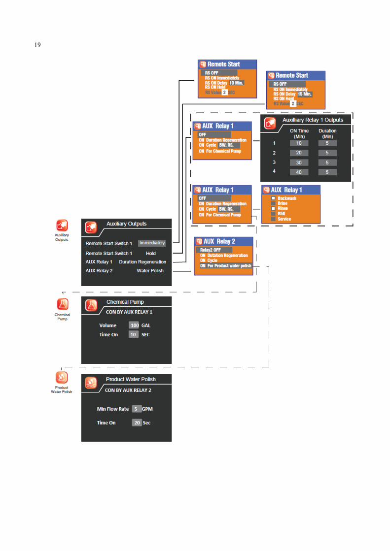
From the Advanced Settings menu, press the UP / DOWN button to highlight the Auxiliary Output menu icon. Press the SET button to enter.
Auxiliary Outputs
Remote Start Switch 1 and 2 There are 2 inputs for remotely starting a regeneration. One input is reserved for an exter-nal switch like a push button wired to a control panel as an example. The second input is reserved for an input signal from other devices such as a pressure switch that could signal a regeneration. RS OFF is the default value. RS ON Immediately would signal a regeneration as soon as the remote button or switch is pushed. RS ON Delay would signal a regeneration to start at the end of the delay period. RS ON Hold would signal a regeneration when the remote button or switch is pushed and held on for the RS Value.
AUX Relay 1 & 2 There are 2 programmable outputs controlled from the start of a regeneration. The default is OFF. ON Duration Regeneration would open the relay output signal at the start of a regeneration. Up to 4 steps may be programmed in this mode. In the On Cycle option you can select which cycles the relay output signal should be on for. All, some, or none of the cycles can be selected. On for Chemical Pump or Product Water Polish may be selected to designate the relay to control these options.
19

20
Formatting Slave & Master PCB’s
For standard MTS system single valve the default Valve Type is BNT 950. For the 2 piston valve the type is BNT 950-X When changing from different System Types, a page will displayed that will confirm you want to change the System Type. Select Yes to change the type and No to keep the current settings. A System Setting page will be displayed. Press the MENU button to exit the Sys-tem Setting page and return to the Main Menu. If you wish to erase the current valve history (Diagnostic Information), it will be necessary to format the slave PCB’s. If you are changing a master PCB and want to restore the history and settings you need to restore history and settings. The Format Slave Valve function wipes out all the stored settings in the slave PCB. The Re-store History Data function will upload the stored settings from the slave PCB to the main PCB. The Restore Settings function will transfer the saved settings from main PCB back to the slave PCB. Re-Format (Erase) Slave PCB Settings & History Data If you wish to reset the history (System Diagnostics) back to zero and start tracking new data the Slave PCB’s can be re-formatted. You may choose the individual Slave Valve No. or ALL. When you press enter, the history data will be erased and set to zero values. Restore Main PCB Settings If you replace the main PCB, you can restore the current settings and history from the Slave PCB’s to the Main PCB. Select Restore History Data to restore history data from Slave PCB’s to new Master PCB. Select Restore Setting to restore valve settings (People, Hardness, Backwash Time, etc,) from Slave Valve PCBs to Main PCB.

21
MTS Wiring Schematics
Softener or Filter Wiring Diagram
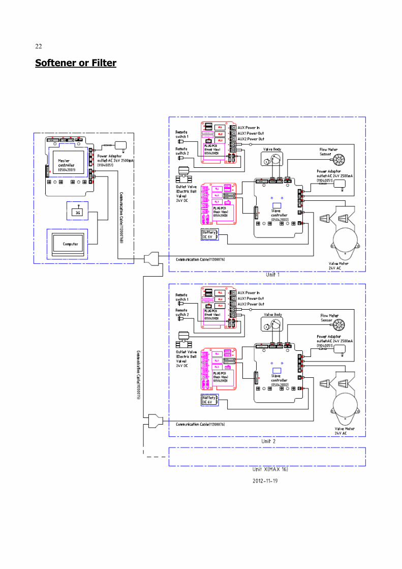
22
Softener or Filter

23
Softener With Polishing Recycle Option

24
Filter With Pressure Differential Switch Option

25
Removing Power Head Assembly
Manually remove the Power Head Assembly: Press and hold Manual Button With 8 hex key, insert Cam Hole, turn the Cam anti-clockwise to the marked position Remove the Connector Remove the Locking Bar Pull the Power Head Assembly outwards. Automatic remove the Power Head Assembly: Unlock the screen Press and hold Down button, the valve will advance the Cam to the marked position Remove the Connector Remove the Locking Bar Pull the Power Head Assembly outwards.
Maintenance

26
Replace Drain Line Flow Control (DLFC)
To replace the Drain Line Flow Control (DLFC): Remove the Clip Pull the Drain Elbow outward Pull the DLFC Holder outward from the Drain Elbow Replace the DLFC
Replace Brine Line Flow Control (BLFC)
To replace the Brine Line Flow Control (BLFC): Remove the Clip Pull the Brine Elbow outward Pull the BLFC Holder outward from the Brine Elbow Replace the BLFC
Drain
Elbow
Brine
Elbow

27
Replace or Cleaning Injectors
Sediment, salt and silt will restrict or clog the injector. A clean water supply and pure salt will prevent this from happening. The injector assembly is located on the right side of the control valve. This assembly is easy to clean. To replace the Injectors: Shut off the water supply to your softener and reduce the pressure by opening a cold
soft water faucet. Remove the Connector Remove the Screw Slightly pull the Injector Body and Injector Cover outward Slightly pull out the Screen Replace the Nozzle Slightly pull out the Air Disperser Replace the Throat Reassemble using the reverse procedure Note: Carefully flush all parts including the screen. Use a mild acid such as vinegar or Pro-Rust Out to clean the small holes in the orifice and throat.

28
MTS System Components
10010055 VALVE BNT950 MTS (SLAVE) 4" C/W 1.25" BALL VALVE
10010056 MTS MAIN CONTROLLER
60010182 MTS COMMUNICATION CABLE 2M
60010197 MTS COMMUNICATION CABLE 6M
60010083 MTS POWER TRANSFORMER 120V INPUT 24V OUTPUT

29
1.
1.
2.
3.
3.
4.
1. 80040050 63MM UPVC TEE PLAIN
2. 80040051 63MM UPVC DOUBLE UNION BALL VALVE
3. 80040052 63MM X 2” UPVC (P/T) SOCKET
4. 80040053 63MM UPVC PIPE 4M
5. 80040057 63MM UPVC PIPE CLIP
6. 80040058 50MM UPVC DOUBLE UNION BALL VALVE
5.
6.
INLET (2”MNPT).
OUTLET (2”MNPT).
CONNECT TO BRINE TANK
30
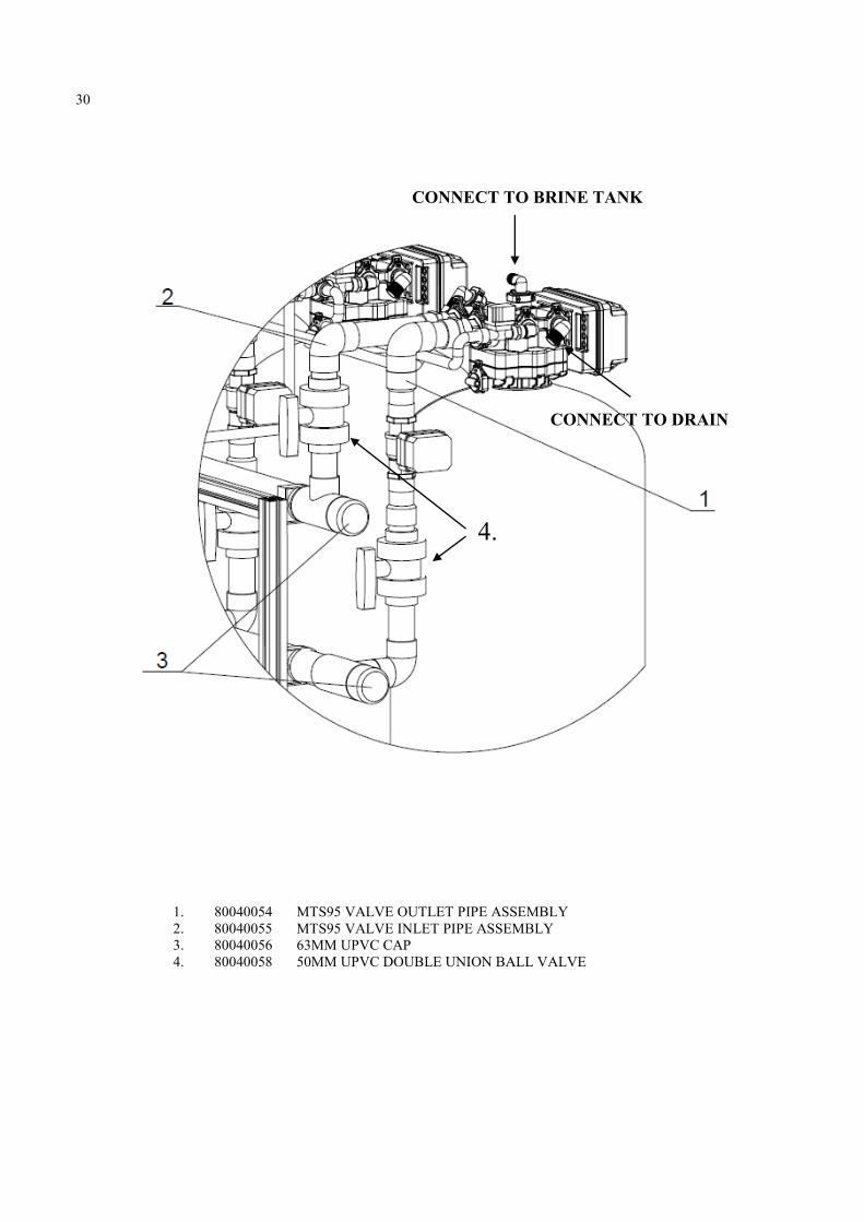
1. 80040054 MTS95 VALVE OUTLET PIPE ASSEMBLY
2. 80040055 MTS95 VALVE INLET PIPE ASSEMBLY
3. 80040056 63MM UPVC CAP
4. 80040058 50MM UPVC DOUBLE UNION BALL VALVE
CONNECT TO BRINE TANK
CONNECT TO DRAIN
4.

31
80040054 MTS95 VALVE OUTLET PIPE ASSEMBLY
80040055 MTS95 VALVE INLET PIPE ASSEMBLY

32
60024290 ELECTRIC BALL VALVE 1.25" NPT MTS
60024291 ELECTRIC BALL
VALVE 1/2”"MTS
80040061 MTS POLISHING PUMP

33
Power Head Exploded View
Item No. Part No. Part Description Quantity
A01 05040038 Bnt95 Cable Jaket(without hole) 2
A02 26010028 O-Ring-Ø28×2.65 1
A03 05040086 O-Ring-Ø8×2 2
A04 05040005 Bnt95 Housing 1
A05 05040008 Bnt95 Driving Cam 1
A06 05040032 O-Ring-Ø4×1.5 1
A07 05040009 Bnt95 Driven Cam 1
A08 05010078 Magnet-Ø4x3 1
A09 05040095 Bnt95 Brine Valve Connector 1
A10 05056085 Screw-ST2.9×9.5(Large Wafer) 7
A11 05040052 Bnt95 Sensor Pcb 1
A12 05010047 Friction Point 6
A13 05040007 Bnt95 Mounting Plate 1
A14 05056084 Screw-ST3.5×13 10
A15 05056129 O-Ring-Ø23×3 1
A16 05040054 Bnt95 Meter Cable 1
05040039 Bnt95 Meter Cover 1
05040037 Bnt95 Cable Jaket(with hole) 1
05040086 O-Ring-Ø8×2 1
A17 05040053 Bnt95 Power Cable 1
05040037 Bnt95 Cable Jaket(with hole) 1
05040086 O-Ring-Ø8×2 1
A18 05040087 O-Ring-Ø5.5×1.5 4
A19 05040044 Bnt95 Motor Pin 1

34
Control Valve Exploded View
Item No. Part No. Part Description Quantity
A20 05040047 Bnt95 Motor (AC12V,2RPM) 1
A21 05040046 Bnt95 Gear Spring 1
A22 05040040 Bnt95 Gear 1
A23 05040033 Bnt95 Piston Rod Bush 1
A24 05040041 Bnt95 Manual Button 1
A25 05040085 O-Ring-Ø10×2.5 1
A26 05040051 Bnt95 Main PCB 1
A27 05056529 Bnt465 Button 4
A28 05040043 Bnt95 Housing Seal 1
A29 05040036 Bnt95 Clear Cover 1
A30 05040006 Bnt95 Cover 1
A31 05040092 Bnt95 Label (Filter) 1
05040093 Bnt95 Label (Softener) 1
A32 05040026 Bnt95 Brine Valve Piston Rod 1

35
Control Valve Parts List
Item No. Part No. Part Description Quantity
B01 05040025 Bnt95 Piston Rod 1
A23 05040033 Bnt95 Piston Rod Bush 1
B02 05040029 Bnt95 Quad Ring Holder 2
B03 05040004 Bnt95 End Plug Retainer 1
B04 05040024 Bnt95 Piston Rod Holder 1
B05 05040022 Bnt95 Spacer Seal 5
B06 05040002 Bnt95 Valve Body 1
05040049 Bnt95 Nut M6 6
05056101 Nut M5 6
B07 05040104 DLFC #3S (4.5 GPM) 1
05040105 DLFC #4S (5.0 GPM) 1
05040107 DLFC #6S (6.0 GPM) 1
05040108 DLFC #7S (7.0 GPM) 1
05040069 DLFC #1 (8.0 GPM) 1
05040070 DLFC #2 (11.0 GPM) 1
05040071 DLFC #3 (14.0 GPM) 1
05040072 DLFC #4 (17.0 GPM) 1
05040073 DLFC #5 (21.0 GPM) 1
05040074 DLFC #6 (24.0 GPM) 1
B08 05040030 Bnt95 Dlfc Holder 1
B09 05040012 Bnt95 Drainlet 1
A15 05056129 O-Ring-Ø23×3 5
B10 05040015 Bnt95 Plug 3
B11 05040018 Bnt95 Clip (S) 5
B12 05040017 Bnt95 Clip (L) 2
B13 05040034 Bnt95 Impeller Bush 1
B14 05040020 Bnt95 Impeller Holder 1
B15 05040014 Bnt95 Adaptor 2
B16 05040019 Bnt95 Impeller 1
A08 05010078 Magnet-Ø4x3 2
B17 05040045 Bnt95 Impeller Pin 1
B18 26010030 O-Ring-Ø48.7×3.55 3
B19 05040084 O-Ring-Ø14×3 3
B20 05040013 Bnt95 Brinelet 1
B21 05040031 Bnt95 BLFC Holder 1
B22 26010046 O-Ring-Ø27×3 4
B23 05040010 Bnt95 Injector Body 1

36
Item No. Part No. Part Description Quantity
B24 05040112 Bnt95 Nozzle-4S 1
05040113 Bnt95 Nozzle-5S 1
05040059 Bnt95 Nozzle-3 1
05040061 Bnt95 Nozzle-4 1
05040063 Bnt95 Nozzle-5 1
05040065 Bnt95 Nozzle-6 1
B35 05040117 Bnt95 Throat-4S 1
05040118 Bnt95 Throat-5S 1
05040060 Bnt95 Throat-3 1
05040062 Bnt95 Throat-4 1
05040064 Bnt95 Throat-5 1
05040066 Bnt95 Throat-6 1
B25 05040099 Screw-M5×55 (Hexagon with Washer) 2
B26 05040011 Bnt95 Injector Cover 1
B27 05040048 Bnt95 Brine Valve Screen 1
B28 05040027 Bnt95 Brine Valve Spacer 1
B29 05040028 Bnt95 Brine Valve Seal Cover 1
B30 05040050 Bnt95 Brine Valve Rod Pin 1
B31 05056070 Quad Ring 2
B32 05040023 Bnt95 Brine Valve Piston 1
B33 05040042 Bnt95 Brine Valve Seal 2
B34 05040081 Bnt95 BLFC-6 (0.9 GPM) 1
05040083 Bnt95 BLFC-7 (1.35 GPM) 1
B36 05040035 Bnt95 Air Disperser 1
B37 07060007 Valve Bottom Connector 1
B38 05056063 O-Ring-Ø78.74×5.33 1
B39 26010103 O-Ring-Ø25×3.55 1
B40 05040001 Bnt95 Valveset (2.5inch) 1
B41 05040094 O-Ring-Ø108×5.3 1
B42 05040091 Bnt95 Seal Holder 1
B43 05040088 Screw-M6×30 (Hexagon with Washer) 6
B44 05040090 Bnt95 Valveset (4inch) 1
B45 05040082 O-Ring-Ø47×3 2
B46 05040003 Bnt95 Spacer 10
B47 05040021 Bnt95 Piston 1
B48 05040016 Bnt95 Housing Locking Bar 2
B49 05056088 Screw-M5×16 (Hexagon with Washer) 4

37
Trouble Shooting Issue Possible Cause Possible Solution
1. No power supply. Check electrical service, fuse, etc.
2. Defective circuit board. Replace faulty parts.
3. Power failure. Reset time of day.
4. Defective meter. Replace turbine meter.
1. By-pass valve open. Close by-pass valve.
2. Out of salt or salt level below water level. Add salt to tank.
3. Plugged injector / screen. Clean parts.
4. Flow of water blocked to brine tank. Check brine tank refill rate.
5. Hard water in hot water tank. Repeat flushing of hot water tank required.
6. Leak between valve and central tube. Check if central tube is cracked or o-ring is
damaged. Replace faulty parts.
7. Internal valve leak. Replace valve seals, spacer, and piston
assembly.
8. Reserve capacity setting too low. Increase reserve capacity.
9. Not enough capacity. Increase salt dosage.
1. Refill time is too high. Check refill time setting.
2. Defective flow control. Replace.
1. Iron or scale build up in line feeding unit. Clean pipes.
2. Iron build up inside valve or tank. Clean control and add resin cleaner to clean
bed. Increase regeneration frequency.
3. Inlet of control plugged due to foreign
material.
Remove piston and clean control valve.
4. Deteriorated resin. (Maybe caused from
high chlorine or chloramines.)
Re-bed unit. Consider adding carbon pre-
treatment.
1. Air in water system. Check well system for proper air eliminator
control.
2. Incorrect drain line flow control (DLFC)
button.
Check for proper flow rate.
1. Plugged injector or screen. Clean parts.
2. Valve not regenerating. Replace circuit board, motor, or control.
3. Foreign material in brine valve. Clean parts.
4. Unit not drawing brine. Check for vacuum leak in brine line
connections.
1. Drain line flow control is plugged. Clean parts.
2. Injector or screen is plugged. Clean parts.
3. Inlet pressure too low. Increase pressure to 25 PSI.
4. Internal valve leak. Replace seals, spacers, and piston assembly.
5. Safety valve closed. Check for leak in brine line connections.
Replace safety float assembly.
6. Vacuum leak in brine line. Check for leak in brine line connections.
Tighten all connections.
7. Drain line has kink in it or is blocked. Check drain line.
H. Valve continuously
cycles.
1. Defective position sensor PCB. Replace faulty parts.
1. Valve settings incorrect. Check valve settings.
2. Foreign material in control valve. Clean control.
3. Internal leak. Replace seals, spacers, and piston assembly.
4. Piston is stuck in position. Motor may have
failed or gears have jammed or disengaged.
Check for power to motor. Check for loose
wire. Check for jammed gears or gears
disengaged. Replace faulty parts.
J. Valve makes beeping
sound.
1. The piston has not advanced to the next
cycle position properly.
Check for power to motor. Check for loose
wire. Check for jammed gears or gears
disengaged.
I. Flow to drain
continuously.
G. Unit fails to draw brine.
A. Unit fails to initiate a
regeneration cycle.
B. Water is hard.
E. Resin in drain line.
C. Salt use is high.
D. Low water pressure.
F. Too much water in brine
tank.

38
Warranty
Limited Warranty
Fiberglass tanks - 5 years; Control valves and electronics - 5 years under normal use (excludes normal maintenance items such as seals/spacers, pistons & brine valves);-Brine tanks and assemblies - 1 year; All other components - 1 year;-Any other components not manufactured by Canature is limited to the warranty given by the manufacturer of the com-ponent. The warranty is limited to the replacement of the defective parts, FOB our factory and does not cover any payment for damages or labor charges. If a part proves to be defec-tive within the warranty period, it should be returned to the factory, freight prepaid together with information on the unit and date purchased. A replacement part will be supplied free of charge. All products supplied by Canature are subject to the warranties of their respective manufac-turers. RETURN OF GOODS: Authorization number must be obtained before returning any mer-chandise. NOTE: All material returned to Canature must be returned freight prepaid. Goods returned under warranty, found defective – Will be repaired, replaced, or credited un-der warranty, no charge to the customer, return freight prepaid. Warranty does not obligate Canature to bear the cost of field labor or mileage. Goods returned out of warranty for repair and returned to the customer – These will be re-paired and returned at normal charges for this work.
General Conditions Damage to any part of this water system as a result of misuse, misapplication, neglect, al-teration, accident, installation or operation contrary to our printed instructions, damage to ion exchange resin and seals caused by chlorine / chloramines in the water supply, or dam-age caused by any force of nature is not covered in this warranty. We will repair or replace defective parts if our warranty department determines it to be defective under the terms of this warranty. Canature assumes no responsibility for consequential damage, labour or ex-pense incurred as a result of a defect or failure.