note: mil-std-769 has been redesignated as a design...
TRANSCRIPT
NOTE: MIL-STD-769 has been redesignated as a Design Criteria Standard. Thecover page has been changed for Administrative reasons. There are no otherchanges to this Document.
MIL-STD-769J(SH) 9 OCTOBER 1990_
SUPERSEDING MIL-STD-769H (SH)
8 APRIL 1985
AMSC N/A FSC 5640
DISTRIBUTION STATEMENT A. Approved for public release; distribution isunlimited.
INCH-POUND
DEPARTMENT OF DEFENSEDESIGN CRITERIA
THERMAL INSULATION REQUIREMENTSFOR
MACHINERY AND PIPING
Downloaded from http://www.everyspec.com
M IfSID-769J(SH)
9 October 1990
FOREWORD
1.ThisMilitaryStandmd is approved for use by the Naval Sea Systems Gxnrnand, Departmentof the Navy, and is available for use by all departments and agerrciea of tbe Department ofDefense ..
,., ”
2 &meGAl anrnents (reccprnendatioq edditio~ deletjons) md any perdnent data which maybe of use in irnpruving Uris document should be addmsaed to: Commander, Naval Sea SystemsCamrrm@ SEA 5523, Department of the Navy, WashingtnU DC 20362-5101 by using the self-addrcssed Standmhm“ tion Dxument Improvement Propmd (DD Form1426)appearingattheendofthisdocumentofbyletter.
3. This standard covers basic thermaf insulation requirements. llre information cnntained in thisstandard ampliks lhe requirements for insulation of piping machiieq, uptnkes and mechanicalequipment avered in the General Spccilicatinns for Ships of the U.S.Navy or in ship specificationsfnr individual ships or cfasses of ships.
/
ii
Downloaded from http://www.everyspec.com
M1lASI1l-769J(SH)9 October1990
.-CONTJ%NTS
Pmngrapfl Pnge
1... 1.1
22121.12122223
3.
4.4.142434.44.s4.6
5.5.152535.45555.15.5.1.15.5.1.255.1355.1.455.1.55.5.1.65325s355.45.55
. 53.6
SCOPE ........................................-.....-.1Pm’pose................... .............................1
APPIKAEX.EDOtXMmm....... . . . . . . . . .. - . . ..- . . . ...-...1Govcromult *cots . . . . . . . . . . . . . . . . . . . . . - . . . . . . - . . . . - . . . 1
Spaifications andstambm k.... . . . . . . . . . . . . . . . . . . . . . . . . ......1Otbcr Gxrnmcnt drawings mIdpubH@om . . . . . . . . . . . . . . . . . . . ...2Non—Gowrnmutt publications . . . . . . . . . . . . . . . . . . . . . . . . . . . . . . . . . 3
Ordcrofprcccdcnce ..:...... . . . . . . . . . . . . . . . . . ...-”... -.....4
D~ONS . . . . . . . . . . . . . . . . . . . . . . . . . . . . . . . . . . - . . . . ...-.4
GENERAL REQ~ . . . . . . . . . . ..- . . . . . . . . . . . . ...-..-4
Nomioalthickncs= . . . . . . . . . . . . . . . . . . . . . . . . . . .............4Spczial conditions . . . . . . . . . . . . . . . . . . . . . . . . . . . . . . . . . . . . . ..-10Adb=ivcs . . . . . . . . . . . . . . . . . . . . . . . . . . . . . . . . . . - . . - . . . . ...10Fmisbingccmcnts.........-.........................-....11Metallagging...........................................11FM~= ................-.............................11 .
DEIWLED REQ UIREMmm . . . . . . . . . . . . . . . . . . . . . . . . . . . . ...11Hot-surfaceinsulation covers . . . . . . . . . . . . . . . . . . . . . . . . . . . . . . . . 11
t%isttuction . . . . . . . . . . . . . . . . . . . . . . . . . . .................12Fabric.atio~pipingmntponcnts.............................. 12
Fabricationmachineryandquipmmt .........................-13Installation.........................................-...14Hotaufacchxwcation... .... ..............................14Pipeandtubing..................................”.......14Pipiogcampcmcota. . ....... ..........................--..14Machinctyandaluipmcnt 14.................................-
8oilcruplakc5............................”.-......-.....15Utdifcd pressure vcsuJs . . . . . . . . . . . . . . . . . . . . . . . . . . . . - . . . . - . 15
Outcrboilcrcaaing . . . . . . . . . . . ......................... ...15Antisw@ioaukXion (coldandchillcdwatcr )service . . . . . . . . . . . . . ...16Rcftigcrantinsulation . . . . . . . . . . . . . . . . . . . . . . . . . . . . . . . . . . . . . 16
Wcatber deck hot pipioginSuhtion . . . . . . . . . . . . . . . . . . . . . . . . . ...16
Metal laggiog . . . . . . . . . . . . . . . . . . . . . . . . . . . . . . . . . . . . . . . . . ..18
Painting, . . . . . . . . . . . . . . . . . . . . . . . . . . . . . . . . . . . . . . - . . . . ...18
...111
Downloaded from http://www.everyspec.com
MIL-STD-769J(SH)9 October 1990
CONTENTS
Pstragmph Page
.6.6162636.4
Tables
LJLm.
IV.
v.
VL
w.
VuLIX
x.
NOTES ................................................18Imrrdedrrse..’............. ............................18Acquisitionrequirementa...................................18Subjecttenn(keyword)listing...............................18Change9fmmpreviorn issue . . . . . . . . . . . . . . . . . . . . . . . . . . . . . . . . 19
Insulation and lagging materials . . . . . . . . . . . . . . . . . . . . . . . . . . . . . . . . 6Thickness ofinaulation for bot piping moforming to MffA-2781 . . . . . . ...6Thickncssofinsulation eonformingtohUIA-24703 aodMIIA-22344,for hot piping . . . . . . . . . . . . . . . . . . . . . . . . . . . . . . . . . . . . . . . . . . ...7Thisknesa of insulating materials for hot surfaces of valvesand Gttings upto1200degnxs . . . . . . . . . . . . . . . . . . . . . . . . . . . . . . ...7Thkkocss of insulating tape eonforrning to MfL-G2C079, MILI-16411,typeIIorMfLI-231~ gnrdeAclaaa2for l/4t03/4-inchsizehot piping . . . . . . . . . . . . . . . . . . . . . . . . . . . . . . . . . . . . . . . . . . . . ...8~CkOCSS Ofinsulation materiak for hot sti~
ofmacbirrcryaod equipment. . . . . . . . . . . . . . . . . . . . . . . . . . . . . . . . ...8
lW&ncsa ofplaaticfoa~ MILI-24703, refrigemrrt insulationfor piping . . . . . . . . . . . . . . . . . . . . . . . . . . . . . . . . . . . . . . . . . . . . . ...9
Tbirkrteaa ofrefrigermrt insulation for maebirtery aodequipment . . . . . . . ...9
‘l%ickneas of antisweat insulation materials for machinery and equipment
(exekiveof vaporba rsier).. . . . . . . . . . . . . . . . . . . . . . . . . . . . . . . . ...9
Nominal thickn- ofinsulation for weather dd hot piping . . . . . . . . ...9
4
iv
Downloaded from http://www.everyspec.com

MIL-SID-769J(SH)
9 ~ober 1990
1. SCOPE.
1.1, Purp&L The purpose of ths standord is to preserii the requirements for thermalinsulation of pipin~ machinery, uptakea and m~htmieal equipment for ship of the U.S. Navy.
2. APPL.fCAflLJ? DOCUMENTS
Z1 Government doenmenta.
21.1 Spedtlrntions and standards. The following apeeifieations and standards form a part of
tfrii doeurrtent to the atent specitled herein. Unfcss otherwise speeifid tfre issues of thesedoeumenrs are those listed in the issue of the Department of Defense Ink of Speeikations andStandards @ODfSS) and supplement thereto, ated in the sofieitation (ace 62).
SPECJFfCATfONS
FEDERAL
HH-P-31
Tr-P-38
Tr-P-320
UU-B-790
MfLtTARY
KfI/T-2118
MILxz7Bl
MfL1-2818
MDA-2819
MfLC4861
MJLA-3316
DOD-P- tS328 z
Paeking turd Lagging Material, Rbmus Ghts Metallic and Plain Clothand Tape
Paint, Afuminum, Heat Resisting (1200 T)
pignren~ Atuminurm Pov.der and Paste for Paint
Building Paper, Vegetable Fitreti (Kraf~ Waterproofed, WaterRepellent and Fire Resistant
TrafL Sttx~ llrermostati~ Naval Shipboard Use
fnsalatioq Pipq Thermal
Irtsufation BfankeL TlsermaL Fibrous Mineral
Insrdstion BloeJq lkrmal
CemmrL Insulation High Temperature
Adhesives, Fue-Reaistun~ T%emml fnwfation
Primer (Wash), pretreatment (f%msula No. 117 for Metals) (Metric)
1
Downloaded from http://www.everyspec.com
MILA-16411
MILG200i9
. . . MILI-22023
MIL-I-22344
MIL-G22395
MILrA-24179
DOD-C-245%
DOD-524607
MfLI-24703
MIL-SID-769J(SH)9 October1990
InsulationFelLThermal,GlassFiber<
ClothGlass;Tap& TextifeGIs, and Thread, Glass And WireReinforud Glass
Inwlation FCIL Thermal and Sound Absorbing FelL Fibrous Gl~Flm%le
Insulation, Pipe+ Ttserrrm~ Fibrous Glass
Comrsnund,End ScafinE,ThermafInsulationPipeCoverinE-.Fire-.Wat&., and Weather-R&istsutt
-.
Adhes~ Fiexiile Unieeflufar-Plastic Thermal Insulation
Coating Compormd$ Nonflamin& F~Proteuive (Metric)
Enamel, Interior, Nonllaming (Dry), Chlorinated AU@Surrigloss (Metric)
insulation, Pipq Polyphosph~e Sheet and Tubular
Resin,
(Unfess otherwise indicat~ mpies of federal and rrrifitaryspecilleations and standards are avaifablekm the Standardization~ments OrderDeslqBld~ 4D, 700 Robbirrs Avenue PbifadefphisLPA 19111-5094.)
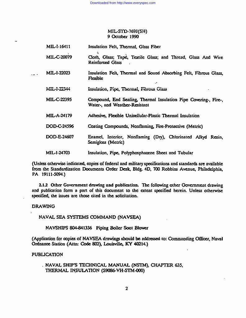
21.2 Other Government drnwlng and publieatinn. The following olher Government drawingand publication form a part of tfsii decument to the estent speeified herein. Unless otherwisesfKdi~ she issues are those sited in the solicitation.
DRAWfNG
NAVAL SEA SYSIEMS COMMAND (NAVSEA)
NAVSIUPS S04.S41336 Piping Boiier Saot Blemer
(Application for copies of NAVSf3A drawings should be addnmed to: Chtrnaodistg Officer, NavalOrrfnan= Station (Attsu t%de S02), Iauisvilfq KY 40214.)
PUBLICATION
NAVAL SHIP’S TECHNICAL MANUAL (NWM), CHAPTER 635,THERMAL IN.SUIATfON (S908&VHSMtJ00)
2
Downloaded from http://www.everyspec.com

MLSTD-769J(SH)9 October1990
(Copies of NSTM required by contractors in esxrncction with specific aq.isition functions shouldbc obtained from the wntmcting activity or as directed by the mrrtrocting activity.)
2.2 Non-Covermment prrblhmtions. The following documents form a part of this documentto the extent specifred hcreim Uofeas otherwise specified, the issues of the documents wlich areDOD adopted arc those listed in the issue of the DODISS cited in ~e solicitation. Unlessoth- Sfrecifid the issti of documents not listed io the DODISS are the issues of thedocrrmeots ated in she aoliotation (see 62).
AMERICAN SOCD?fY FOR TESTING AND MAIERJALS (m
A 167
AS26
B209
c 449
c 595
D3400
F 113S-88
Stainless and Hsxrt-R&sting Cluomium-Nicke.l Steel PIat~ Shee~ andStrip, Standard Spcdcotion foq (DOD adopted)
Steel ShecL ZhvXoated (Gafvaoisd) by the Hot-Dip P-Commercial Quality, Standard Speciticotion foq (DOD adopted)
Afuminum and Aluminum-AfloySheet and Platq Smsrdrad Specificationfoc (Metric) (DOD adopted)
Mineral Fiber Hydmuli@ettirrg Thermal Insulating and FinishingCurrerr~ Standard Specification fon (DOD adopted)
Blended H@mrlic Cenrertt$ Standard Speei5cadorr fo~ (DOD adopted)
fiquid So&urn Silicates, Standard Specification for
Spray Shields for Mechanical Joints, Standard S~ificstion for
(Applkstionforcopies shoufdbeaddresedtotheAmericanSocietyforTestingandMaterials,1916Race%ec~ Pbifadefph@PA 19103.)
(NOo—Govunmmt standards rmd other publications are norcmdfy available from the orgsnimtionsthat prepare or diatriiute the dotxrmeota. These documents afscs may be avrtifable in or throughIiimriea or other informational services.)
23 Order of precedence In the event of a corrflict betwers the text of this document andthe refcrerrcu cited lrereisL the m of this dearment tokcs prccdeocc Nothing in this document,hO=W% S~ apph~b~ ~ and PW~tiOLM UnlS a specific ~ption h= ~n ob~in~.
/
3
Downloaded from http://www.everyspec.com
—- ——
MIL-STD-769J(SH)9 October1990
.-
3. DEFINfTfONS.,
3.1. Application of the requirements listed herein k limited only to the equipment speeified
in 1.1.
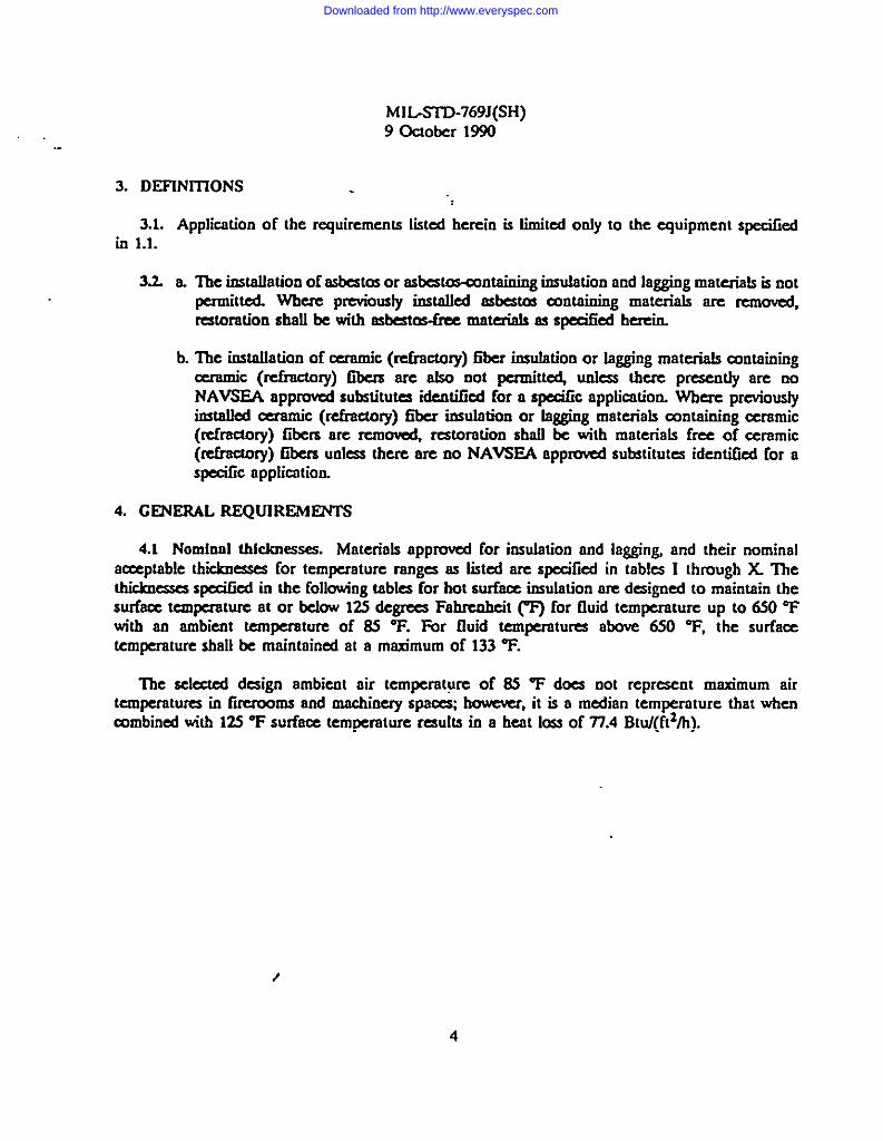
3.2 a llre installationof asbestos or asbestos-containing irtsrdation and lagging materials is not@ttCd. Wb- prc?iousfy irxtalfed asbestos OxMahiag materials are rcfaoved,restoration shall be with ask@s-fru materials as specified herein.
b. The irrstrdfation of ceramic (mfracttrry) liter insrdation or lagging materiafs antainiigcenurric (refmctory) Gbers are also not permit- unks tbcrc prc5eotly are noNAVSEA approved substitutes identified for a spedc application. Where previouslyiastrtfled ceramic (refractory) fiber insufadtrrt or lagging materials containing ceramic(refractory) Gbers arc rcmowd, restoration shall bc with materials free of ceramic
(refractory) IIbcrx unkss there are no NAVSEA approved substitutes identified for aspecific application
4. GENERAL REQUIREMENTS
4.1 Nominol thkloresses. Materials approved for insufsttion and la~”n~ and their nominal
a~ptable thicknesses for temperature ranges as listed are specified in tables I thtrsugh X Thethicknesses specikl in the following tables for hot S* insulation are drsigned to maintain tbesurface temperature at or below 12S degrees Fahrenheit (T) for fluid temperature up to 6S0 Tw“tb so ambient temperature of 6S T. For ffuid temperatures above 650 T, the surfacetemperature shaIl be maintained at a mm-mum of 133 T.
The seleaed design ambient air temperature of SS T does not represent maximum airtemperatures in firerooms and machinery spaces; bowewr, it is a median temperature that whenmmbincsl titb 125 “F surface temperature results in a heat loss of 77.4 Btu/(ft2/h).
Downloaded from http://www.everyspec.com

. .
MILSTD-769J(SH)
L1
II
>ber 1!
!!—
—
—
5
Downloaded from http://www.everyspec.com

hflMTD-769J(SH)9 October 1990
TABLE II. ~
Ncmirulppc&e(ii)
5,6,7
ss of inndation & hot p@ing conjtig to MM-2781.
. .Tcmpcrnt urc
wm
m-388
389-7307s1 -930931 - 103O
m-m339-388389-5U0w] -1036
123-338339-388389-300301-5WSO1 -930931 - IWO
123-338339-3883s?7-7307s1 - w
::: ?&l
123-338339-3883s9 -300301 -7307s1 -930901-9s6931- 1030
I-w/234
l-wZIc33-V244-3L2
l-r/2%m3-V24~U2-s-m
1.1122-IL?z-m44-IK2s6
6
Downloaded from http://www.everyspec.com
MILSTD-769J(SH)9 October 1990
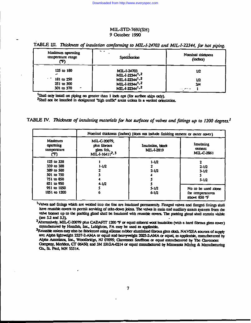
TABLE III. “17uAmx of inndotionconfwmhgtoMI..I-247O3 and MIL-I-22344, for hotpiping.
~w=@3 ---Spdlhrca Naninal~
Uqanmre rangem
(-ii)
12SmlS0 hfIIJ-247u3 2/2~1.27344fc2
‘“ 181m2S0 MIL-2-233441.22Slm300
u.?MfbI-223441.2 ?J4
301m370 - Mf3/3~f,2 . .. . . 1
%211mtyinsmflrnpi pingmgroxerumn liaOps(fcf suf7kcc*@)%2nmlteiMm5.Ahda@mj7@ onf2w2mm lmle$atOawnkafabm12ml
TABLE W. ~ of inndating nmtti.% for hot S@O~ of vdva ond @tin@ q to 1200 dqywz.]
Nominal IMcMMs(ii) (dIxsmxindudc ti&bing mnmIIXOUUYmr)
Mum MU-G20D79,
W==@l @ls Ii&m ~Mck fnsuaing
-P& M23X2S19Mfi?wll%.s
CmlcmML-C-2861
Uz5mms I l-w 2339m~ l-lf2 2 LV23a9m S00 2 2-2/2 3-W301 m 750 3 4 s751 m 850 4 S-IL?821m950 4-W? :%1 m lMO 5 S-I/2 Nombcusedalonc1031 m la 6 &2fz fw mnqm-wums
ntm.emv
7
Downloaded from http://www.everyspec.com
MIL.’7ITJ-769J(SH)9 October1990
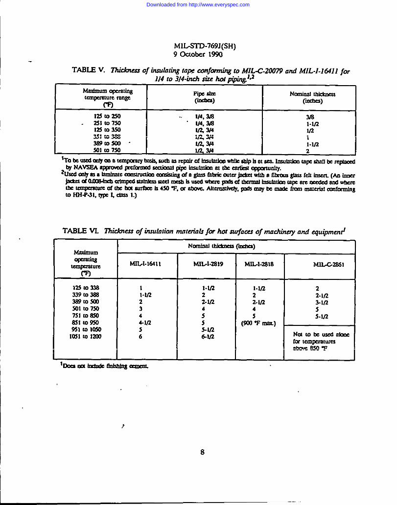
TABLE V. Zhi&ussof insuhting tap wnfbnning to MIL-G21W9 and MIL-I-16411 for114 to 3)4-inch size hol p@in&IJ
himinmmopwating%==&= w
Pi~ size Nomitml thktocu
-) (ii)
mlozso .. 3182s1 10 73a “ 2% l-m12SI03S0 m331t03m Zz 1389tosoo - a2f4 l-w301 m 7s0 lR3i4 a
TABIE VL 77icbxs of insuhwn materials fbr ho: s@acu oj machinery and quipmed
I Norniml “Malimum
Ib&OcQ(id%aa)
-T
KL[-16411 w3x3S19 hi31/1-2818
125t033a339mw38910300301107m7s110m8S1109S0951la10541031m IZaJ
,.
I-U22344-IR56
1-1122%ln
:55-V!6-W?
1-1/222-1124
(safJ5Tlrom)
bOcsOOtindlJ6canbbbIgoman
?
8
t.uLG2&51
22-V2Z-in
:.V2
Ncdtotcusdhb Iempmtum
abobcuo-p
Downloaded from http://www.everyspec.com
_ .
MHAWD-769J(SH)9 October 1S90
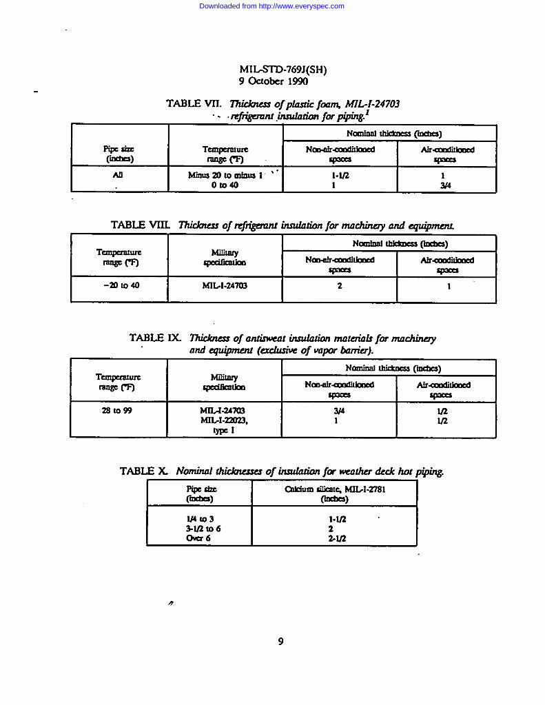
TABLE VII. “~ ‘f P? f- hfIL-I.24703
“- @i!P~.~ [email protected]~ @xbcs)
Fycky Toqermmc NmdruuMbxE6 AirUmamcclWm q=== -
All Mimm2010mlaml ‘“ l-w? 1Oloa 1 2f4
TABLE VIIL “~ofti+~ - jwnlachirray andcquipmc?u
Nomiml~ (kales)Tan$cnwm
-m Nmdradikxwd Alrumlibxdw= w
-mlo40 MIL1-24703 2 1
TABLE IX “~ of ONinwalhrdahon“ mafaialsf9r tnochinayandCquiprrlau(aclusiwof vapor bwlier).
Nominaltlridms @c4cs)Tanptra!um-m --h Nm.drudiOmd Alr-mwMmc6
w= v==
2ato93 MlLKwo3 whtrL1-22023,
U?1 V2
ml
TABLE X Nominal “~of~ “ jamxher&khotP @ng
Pipesim CxkiumsilicmqKILI-278]-) O@=)
IU4103
I
l-mM/2r06 2ckt6 >U2
9
Downloaded from http://www.everyspec.com
MIUTID-769J(SH)9 October 1990
4.2 Special conditions. The foIlowing s@aI renditions supplement or mcdify the selectionof matm”als or thicknesses spcciliq, when applicable
a.
,..b.
c.
d
e.
f.
‘llre insulation thickness on soot blower piping betwccrr the mot valve and the sootblower heada shrdl be reduced to onrihoff that indicated for a system normaIIy at thesame temperature...
‘ For repair or replacement of piping md machinery insulation, only the materialsseed herc~ sh]l be used. Procedures for tbe repair and replacement ofinsulation are cmrtairred in Naval Ships Tecbrricaf Manual (NSTM), Clrapter 635.
Where HOT SURFACE insulation thicknesses are not specifi~ and for special
aPPfi=tio- the ~ulation rhib= @ be sfidmt to reduce the insulationsurface temperature to the values shown in 4.1.
Adhesives containing halogenated solvents shall not be used for submarineapplications.
Insulation shall not be irratallcd on two feet of pipe immediately upstream ofthermostatic steam traps, complying with MILT-21 la A removable cover, consistingof two la~ra of glass cloth shall bc instdlcd over the unirr.xdatcd pipe and thethermostatic trap.
Smofl diameter hot piping l/2-inch nominal pipe size (rips) and under shall not beinsulated when the operating temperatu~ arc less than 12S T.
Shielding on uninaulatcd hot pipes shall be pmvidcd only where such pipes arcreadily a=ible to contact with personnel.
IkfWI-2781 shall be used in “hicfr tra5c- areaa ‘Hi@h traffic” areas are those areaswhere the installed insulation a~d lagging will be su~at to war and damage ”dunngroutine operations.
43 Adhcaivcs.
a Adhesives conforming to MLA-3316 shafi be used for fastening Gbmws gfoas cfothand tape lagging. Rcwetrable lagging is a~rable provided the end result is
b. cxmfornrhrg to ML-A-2A179 shafl be used to secure EYPELApcdyphcopbarzrre irrsufotion conforming to MILI-24703 to itself and to merafa
c sodium silicate solution, ASTM D 34tXl, ahafl be used 0s an adhesive for joiningKSC.~rS OfCdc.iUIItSikOlepreformed pipe irrsdation in accsxdance wjth MLl-
.,
10
Downloaded from http://www.everyspec.com

MILSTD-769J(SH)9 Gctober 1990
4A Finishing cements. Where Gniuhing cement is spezified, any Of tbe foflowing materiafsare acceptable Prior to ~ material “compau%ility w“tb the proposed application will be verified.
a finishing cement in accordance with ASl14 C 449.
“b. High-tenrperalure insulating cement in accordance with MIfAX8dl, when usedunder fibrous gfsss cloth.
Q A mixture of 80 percent high-temperature insulating cement in aczmfmsce with h41LC2861, and 20 pereent cement in aeusrdan= with AWh4 C 59S.
45 Metal Ia@sg. Where metal fagging is required, any of the following materials areaceeptablq except for uptake applications (s& ‘~1.4~
Sheet material Sped fkatfon
Hotdipped ASIMA 526 *gafvnnti steel coating da”gnation
G-1 15
Afuminum ASl%f B 209,6061
COrmsion-resistant ASl?vf A167, type304steel
Nomlml thkkness
0.014
0.030
0.014
4.6 Fasteners. Insulation shall be held in place by suitable wire or flat metal bands Thewelding of fsstenera to machinery, piping pressure vessels or other related equipment is prohibited.Where fasteners are neeessaty, thq shall be attadsed during manufacture (prior to heat treatment,stress relief and testing) by a NAVSEA approwd procedure
S. DfH’AII,ED REQUfREMFNTS
5.1 Hot-surface Iasafntfon cuvera In odes to ensure that the pipe covering will 001interfere with the aavidng of a takdmvn joint where a reusable cover is instaff@ the permanentinsolation shafl stop short of the takedmm joint and a abort removable and reusable section ofirssufation shafl be instaffed between the pmnanent insulation nod the takdovm joinL Theinsulation joint formed by the pexrnaneot and reusrdsfe seedons may be aqua= or at an angfe of45 degnxs, The reusable sedion sfsdl fit tightly at tfse interhang joint witbout”gsps and shaIl be
befd in pface w“tb removable pb dim wi~ or bmsds to nutfntain a tight joinL
11
Downloaded from http://www.everyspec.com
MIL-STD-769J(SH)9 October1990
s2,Construction.l% sizeslargerthan2-inchn% vahebonnetsand valves having takedcnvrrjoints at the ends shafl be fitted with reuaobIe mvess such thai the bomet joint may be removedindeperrdentfy of the vsrfw covering. Vn~ 2-inch rtps aod under, shall be Etkxl with separatecovem m indicated ax or covers of a one-pieee design such that they may be wrapped amuodthe entire valve body ond clipped or olhenvise secured just below the packing gland on the valvestern. P8ckirrg gland shau remain visible
- S3 FabrknUo~ plpiag eom~nenta. For piping components except as otlre- specifi~soy one of Ure folfowirrg metheds of fabrication k aacptablc
53.1 km that ore csposed to temperatures under 4S0 W may be made irr tws hrdf-sedio- using Gbrorrs glass felt in accordance with MffA16411 encfosed in fibrous glass fabriceortfortrriog to MIXZO079, type I, & 9. Aftenratively, silicone rubber costed, afunrinid glassfabr# may be substituted for plain fibrmus glass fabric for the caver raateriaL Covmx that oreexpased to temperatures of 4S0 “F ond rxer shalf bow o 0.00Eiich diameter knitted stainless steelwire mesh stwrr on to the fibrous glas elotb on the inside (hot) surface and on the endsAkernativefy, the inside surface and ends of pads maybe fabricated of wire-reinforced fibrous gfasscloth oxrforming to HH-P-31, type I, class 1. Each half cover shall he sewn and quifted withpolytemafluoroethylmre (PTFE) tooted fibrous ghrss yarr-csxrforrrring to MJLC20079, type HI,classes 3,4, or 6 for hand seviin~ or PTFE coated Iibrous glass sewing thread (fully sintered), type~ classes 3,5, or 6 for machkre sewing. The covers may afso be fostened by mechanical staplingtitb galvanized or stainless steal staples in a manner to provide uniform thktmess, strength, andrigidity.
SS.1.1 Knitted w“re mesh shall be of 304 ameafesf stoinks steel. ‘flrc w-m shall be 0.tX18-
inch dmeter. ‘fhe m~h shall consist of 7-112 * 1/2 murses per inch equal spacing and 10 * 1woks per inch equal spacing. ‘he mesh shall be furnished in 30 * 1/2 inch flattened tubular formand shall be erirrrped 0.12S to 0.150 inch deep by 5/16 inch crimp to crimp.
hpprwd rourusforSitimncrubtu matq Sru- graslfame Ore0s rattms Atpasughwei@rt3337-2-AMAmsquatarD3rEmpd@r2cr23-2AMAorsquaLOsappldMq maoufraredtyAt@aAssaiOlrs,tar i,wOYmrkt~ NJmulrrmmr sdrrcororcquatarsaufaoured trylmccsamnml = ~ ~ 064% ond 3MSRGAU2MorCqustmmufamdtyhtii Miairrg& Manukuriag Ox SL Pa@,MN55144.
/
12
Downloaded from http://www.everyspec.com

MIL-STD-769J(SH)9 October1990
.5&? Preformedlitmusglassvabeorfitting covers may be used when temperatures ore in
he 12S to 370% rangeTheseshallbeofthesamesMcknessastheadjaeurtpip eovcrirr~Sucheovem, when wed, shall be lagged independently of the pipe covering and in a manner which willfaeihtate removal and I’C.pk@CMCrIL
533 Cows may be made of segmeots of blor& insulation or preformed pipe insulation,having the same thickness as that on Use adjacent pipin& B1oeks shaIl be aearefy wired to fmrnesof l/2-ioeh square mes~ number 18 gauge. (0,049-inch diameter) gabanid e.tecf wire. Wke meshframes inside and outaide of blocks aball haw ends bent m and joiita secured with number 18gauge bfaek annealed ironwireWJWOthrough the mesh. High temperature cement in aeuxrfaneewith M3L-C2861 sbaff be truwe.fed smoothly over all surfaces of the wire mesh Fibrous glass feltin aoxxdanee with MII/I-16411 maybe used to build UP arver’a when tie flange diameter is larger
than the outside diameter of the adja~rrt pipe eowrin~ Covers shafl be tightfy and smmthfy laggedto envefop the outside and errd$ using Gbmur glass efoth conformingtoh41L.-C2fM379,type~ elros9.‘@gingmaybeeithereententedorsewnOILexceptendsofcoveqwitiebshrdlafwayxbesewnWheredoublefayerinsulationisused,thew sectionsofthecovershaflbeGttedtogetherwkhscarfedjoinLSuchjointsshrdlbestraightandtrue10reduceheatIcms.Bard&eyeletsorlocksofgalvanizedstil,orlacingwithhooks,rings,washersandw“reshallbeusedtosecuretheeovem.
S3.4 When iostaffing the above ~ spaeu between inner surfaces of rnmrs for flanges
and other irregular surfaces sltdl be Gfkd titb pi- offibrousglassinsulationfeftinaeeardaneewithMWI-16411. 1%1~shall be packed Iocoe.ly enough to pre$emm air cell structure and tightlyenough 10 prevent air arudation
S3S Preformed mineral wool insrdation with a hard Gbmus gfass cover (CADAFIT 12CKITjor qual may be used as applieabl~ For titckness of CADAFIT 12MJV or qunl mineral woolimuhxion refer to the Uridme$ses shown in table II at the appmpnate tempermure nmge.
5.4 Fabrimtfo~ mnchlnery and equipment. For reusable eovem for maclrhery andequipmen~ either of the following methods of fabrimtion is aeeeptabl~
5.4.1 Ckwetssirrtifar to fibrous glass felt in aeeordanoe with MII--I-16411 deserii for pipingarmponents (see 53.1).
SA.2 Covers made in sections formed of irrsufating block befd together with wire and adheskeemerr~ covered with Wii thiekoeas of fhishirrg eernerr~ ASl?vf C 449 and lagged. IArrg withbemheirr~washers mrdwireorbrassanap fastenem sftalfbe usedt6aeeure tbcmvers.
w“ Smwmmmabk hrrbioe eaaingoange amem may beitratafled staaetaftemati forrenrovabfe covers specified above The permanent insulation shalf be run to the eas’mg flarr~affowing for bolt removaf apa~ The ffange and bolts shafl be covered with 6brous glass cloth inaeeordanee with hffL-GXs079, type ~ wire insermd Gbmus glass elotb in aecordaoee with HH-P-31, type ~ ekt.xs 1, or bitted w’k mesh as required by operating temperatu~ titch shall beaecumd to the bolts .yitb wire llre flange shallthenbe insulatedwithfibrousglassfeltin
13
Downloaded from http://www.everyspec.com

MIL-STD-769J(SH)9 October 1990
accordance with MIL-I-164 11, m“neral wmol felt in accorrhm- w“th MXJA-281& or insulation blockin accadstnce with MfM-2819, cJass 2 to the required Utickncss and shape llte insulation is thenlagged with fibrous glms cloth, ‘kfrich shall be carried nwzr the outer edge of the permanentinsulation aad sccurcd with adhesive The semi-remcwable cover shaIl then be scaled w“th adhcsiw
in acurrdarrrxw“thhfILA-331&class1,andpainted.
S5 Inatnlfntion.
5S1 Hot-arrrfnes iasnfation.
S.S.1.1 Pipe and tubing. Each layer of molded insulation shalI be instrdlcd witi joints buttedtogether. Wberc two Iaya-a arc used, joints shall be staggered. Not less than three fastenings shallbe used for securing ertcb 3-foot section of irrsufadon. F=tcning shall be number 18 gaugerrrinkrmm(0.OWrdr diameter) annealed black or hotdippcd gafvanirzd imn wire or W: steelban& lkept m otherwise ~“ficd, lagging shafl be installed over the insulation.
S,S.1.1.1 The installation of soot blower piping insulation shall be in acmxdarrce w“th Draw”ng804-841336.
S.S.1.2 Piping components. Va~ fittirr~ and accessories with weldd and brazed fittings,irtcfudirrg uniou may be imulatcd and lagged sirdarty to adjacent piping.
S.S.1.2.1 Block or felt insulating matenafs, or molded pipe imulation secured w“th hotdippedgafwmirsd iron or steel wir~ shall be used. When irrsufatirrg felts arc ~ the inner layer sfrdl befibrous gfass felt conforming to lKIJJ-16411. Gah’anized imn or steel wire nettirt& number 18
gauge minimum (0.049-inch diameter), shall be spread over the insulating material and securedw“th wire, fnsulatirtg ctment shall be d to Ill crevkxs smooth surfaces and completely coverthe tie netting. A MZ-inch thickness of finishing cement shaU tbert be applied. Alternatively, wire
netting may be omitted where the size of the installation does not require netting to hold theinsulation cement in place during the installation process For these installatio~ gbw cloth maybe irrstalfed over the previously finished insulation material without the inkxrrrediate layer of wiremesh. Insulating matcrird shall be the same tbickncss as that on adjaant piping.
5.S.1.22 Rerrsnblecovem sfmll be fitted where rmqukesf.
55.33 Macblrrery and sqnlpment. For macbinq and equipmcq blo& feft or blanketbrstdadrrgrasteriak of tbc nquircd thickness sbafl be secured with ftotdipped @wniuxl imrrwireGtdwukd iron wire nettirtg I-inch meab and ttrmrbe.?18 gauge minirnrtro (0.049-ii dimncter),ahaffbc spmadovcr thesurfa~nnd aecuruf bywirelnsufatirrg cenrerrt sbaIlbc used totll*S ammtfr surfaces and ampletely arvcr the wire nesting,
S.S.13.1 When no insulating cement has been speci~ a M?-irtctt thickness of finishingcement shall be applied.
/,
14
Downloaded from http://www.everyspec.com

MHST3-769J(SH)9 Gclober1990
.-S.5.13.2Wlrenaninsulating cement has been specified, it shall be applied in successive laye~
lLMrreh to l-inch in tM~ tu@l the total thieknesa speeilled hro been reaelmd. Wn netting,sim”lar to that used for covering the insulating materiak shall be instaffed betwem fayem A li2-ineh Utielmes of Grrishiog eemeot ahaU be applied over the lastlayerof isrsufstting eeMtXIL
55.133 Lagging sbafl be in@kd over Gnishingce.nrenLReusable mverx shaff be instaUedwhere requi@ .. ,.
.-
S5.13.4 (IS hma or other fastenings for aeeuriag insulation or fstggissgshaU not be brazedor wAded to nonferrous parts of distilling plants or deaerating feed tanks.
5.5.1A Bailer uptakes. Boiier uptake thermal inaufation shall be insulated with either mineralwool felt in acmrdtmce with MILJ-281S or Gbmus glass feh in aceordstnce with MfJA-164 11. Ifamustic absorptive treatment is found to be n~ to decrease the. noise x the insulation
lhiekrress ahaU tc inercused accordingly.
5.S.1.4.1 Metal la~”ng for uptakes shall be galvanizxl sheet steef eonforsrting to ~ A
526, mating designation G-1 15, not less than 1/32 inch Uriek.
5S.1.4.2 Insulation and fsgging is not required on uptakes above the weather dec& aeeptwhere the transfer of heat to apaccs adjamrst to the uptake arm wxtld be objeedonable
55.15 Unfired preaaure vessels. Unfired pressure wssels, irteluding catapult wetaceumulatnr&sbaU be covered with block insulation MfL-1-2819, or Gbrousgfass felt in acmrdmtcewith MIIA-16411. Insulation shall be held in place with 18 gauge galvanized wire spaced onappIOXiMa~b S-ikIeh 0311fXs or at=] strapping apamd on %ineh maximum mtstesx Irrardation shallbe eowred w“th l/2-iieb Gniihing cement in acmrdanee with ASTM C 449, lagged with fibrousglass efoth in accordance with MIIX-20079, type I and painted as specified in 5.S.6. Imulation inthe way of ~ supports shall be rnetal-faced to prevent insulation from wedging between thevessel and its support
S5.1.S.1 Removable and reusable eovetx ahail be irtstafled m butt-wlded sheU inserts forwhich periodic nrdiogrstphic impeetion ofthejointisrequired.These,pvemshaUextend4 irteheabeymd theweldedjoinL
5.S.1.6Onterboilereasing.Ifinsulationiss~fied by perdoentships’spesiflcationoreon- insulationblockinaaordan=withhfIIA-2819,class2sftaUbeaeeuraftoestairrgbywirenetting(number18gauge)lad towefdedmtehedstudson boifereasing.Fag mmesrLASlMC449, sbaUbeusedtofiUerevi~smmtbsurfaS mtdmrrrpfetefymverShenettingto112inchthieknsSGlassefothmnfomtirrgtohfILG20079,typeL classasapplieabl~shaUbeusedtofagtheinsufatinrtsmdsbaUbepaintedasapeciiiedin55.6.
15
Downloaded from http://www.everyspec.com

.
MIL-STD-769J(SH)9 Oclok-sr 1990
5.5.2 Antiswat hrsuintiorr (cold and chilled water serviee).. .
5.S2.1 Arrtkwcstt piping insufrttion shaIl consist of preformed sectiorrrd pipe covering fabricatedof EYPELA polyphcrsphazene insulation (MffA-24703). ‘fhickoess shall be 3M-ioch, 00 all pipe
sti CSUPt in ~r~ndition~ spa% where thickness shall be @iich. On large pipe ~EYPEM&polyphmp_e @dation forro.S may be applied in l/4-iich rninimurnthickrs= Irtyusas neecssmy to build up to the required thickness. Glass cloth la@rrg shall be applied to proteztbrsrdntion from damage in hid time areas.
S.SS Refrigerant insulation.
. 5.SS.1 EYP~A polyphosphaxnc insulation in acczadancc with MUA-24703 maybe appliedin l/4-ir@r minimum thickness Iaym as trecessmy to build up the required thickness (form T orS, as applicable). Longitudirrrd and butl joints shall be staggered. Joints shalI be sealed usingadhesive conforming to M&A-24179. Glnss cloth lagging shall be applied over elastomeric foamedplastic in high tmffic areas to protect against dnmagc
5.5A Weather deck bot piping Insulation.
5.SA.1 Sectional preformed calcium siIicate (MfLI-2781) insulation for piping orposed to tbeweather shall be installed as follows:
a. Preliminary preparation of piping.
(1)
(2)
AU surfaces shall be clean, dry, and free of scale and grease
Fittin& vati flang~ pipe supporting clamp, and at least 3 inches of adjacentpipe shall bc painted as follcrvm Apply one coat pretreatment formula 117 in
accordance w“th DOD-G15328 to a maximum dry film thickness (D~ of
0.CKK)5 inch (0.S roil). After this coat dri~ apply twr coats of afumimrm paintmade by mixing 2 pounds of aftrrrsinum paste in a-rdrmce with lT-P-320, typeII, chss & with each gallon of pherrolic varnish for temperatures up to 300 T.Abou 300 T, apply m coats of paint conformirig to lT-P-2&
b. Installation on pipes.
(1) fxmgitudii joiits on horizontal piping sbrdl be on top and bottom of pi=joirr~ sludl bc staggered.
(2) Insulation shall be sceured tightly to pipcwitb @iich wide 22-gauge grrlwmizedsteel bands or 1&gauge galvanized iron wire on 9-irtcb czxtta
Downloaded from http://www.everyspec.com

MILST13-769J(SH)9 Ostober1990
.
(3)
(4) .
Fdl all joints. and wida in the insulation with high @ra@ture cement inaccordance w“th MIfX-2861. Wrap tightly with one layer of fibrous glasslagging elotlr inaaordarreewithh41LG20f)79,type~ using adhesive inaaurrfance with MJLA-331~ slass 1. After the adhesive has dried, the la~”ngsbafl be mated titb w brush coats of end sealing mmpound in amordsnccw“tIr-M.fIx-z239s. “Where insrdatiorr is stopped off on the pipio& tbe preformed insulation shall
—aetapemd. llleesposed srrrtaccmtd 3irreba ofpifse stra11beeoatedwitbaeafing sompound in accordance with MILG223%. Fibrous glass lagging sJo&in accmdanee with MHAXMM79, type ~ class as applicable tailored to fit overUSCtapered imulation aad cspased pipe abtdf be applied wttife the end sealingeompattd b SW tacky. The faggittg shafl be attached to the inndation usingadheaiw in aaordarree wkfr ~A-331d aad to USCpipe w“tJr a U2-inch wide.22-gauge gnfvarrird steel band.
c fastaffation on fittings, flanges and valves.
(1)
(2)
(3)
(4)
Before applying flange insulation, wrttber deck piping shall be tested and
secured in tbe following mamec After seed tds are completed, weatherdesk piping shall be subjated to altemtate ~“ods of fufl operating pressur<allowing pipe to come to marrirmmrtempxaturq and then to zero gaugepressure allowing pipe to come to ambient tempemtum These @es shall ber’e~ti a sufficient number of time& with tightening and adjusting flangeswhere necessary, until no leaks ean be detated
Fittirr~ flanges and valve sewers shaff be shipfabricated from ~ions of
molded pipe mvenng block mmented together with adhesive in accordance withASTM D3400.
Permanent covem for fittings and vafves shall be Ilted snugfy to fittings andadjaeertt pipe covering using the same material and methods as outlined for pipecovering Voids between insulation and fitting af@ be Gffed with tightiy packedIibmus glass feft in accordance with MIJJ16411. Permanent cam’s shaU belagged and mated in the same manner as the adjamrt piping insulation.
WbemapeciG@ rigid-typererrrovablellangeeaersabaffaterrdovertheadjacent pipe eowxhrg l-1/2 dm= the UrickrIcssof the iasufatioo. Tire NWJbafvcs of tbc uwc.r shaff be coated sad lagged sepamtely, using the samemateriafa and procedure as outfirred for weather dcek hot pipe covering. l%e~s~tids-~~tbe- _togetheraod to theadja-t pipesoverirrgshaUbeappfialow.%thelaggingandthenmatedwithth~end sea(ing compound in accordance with M31AX2395.
17
Downloaded from http://www.everyspec.com

MIL-STD-769J(SH)9 October1s90
d. Installationaruundsupports and hangers.. .
(1) Remove only enough insulation from butt edg~ to provide a snug tit aroundsupport bmekets or hanger rods Fti voids betvmen insulation and support withtightly packed Gbrous glass feft in oaordanec with MILI-16411 to within l/4-ineb frum insulation sut-hec Fill remainder of space with sealing compound, inarmrdan~ with IvflL-G223%, otwlapping generous? both the support member&rd the adjaeurt insulation. Lag and coat w“tb tfre &are method and materials& adjaeurt pipirig.
5.S.S Metal faggfng. Metal la~”n& where requi@ shall be installed with lap joirr~ ‘kecuredwith hardened self-topping screws or metal bands. Joints shall be arranged in a reamer wbieh will
facilitate rruwff of impinging Iiqui&
S3.6 Painting. Cloth and tape Ingging shall be painted after installation with one coat ofnon-Qamirrg paint eamformirtg to formula No. 124 of DOD-E-24607 or water base DOD-C245%or Navy formula 25A if nesxssstry for appenran= Unlagged EYPELA polyphosphozene insulationeonfornting to MllA-24703 shall be sealed with one cat of Devoe and Raynolds ‘DEVLEX 1“or equal to ensure that the insulation &mns remain tighL Both unlagged EYPELApnlyphospfrazrre insulation sealed with TEVFLEX 1“ or equal and lagged insrdation shalI bepainted with tire retardant paint eonforrrringto DOD-E-246fJ7 or water base DOD-C245% orNavy formula25A.
6. NOTES
6.1 Intended use ‘fIre therrrraI insulation speeified in this standard is U@ for the insulationof pipin& maehine~,uptakesandmechanieolequipment used by the Navy for indtidual and classeaof ships-
6.2 Aeqtdsition requirements. Acquisition doeumenrs must s~”fy the followirr~
a Title ❑umber, and date of this standardb. Issue of DODISS to be ated in the solieitatinq and if required, the specific issue
of individual documents referenced (see 21.1 and 22).
4
18
Downloaded from http://www.everyspec.com

MIL-STD-769J(SH)9 October 1993
63 SubJeet term (ksywnrd) listing.
AlrriitBoiler uptakes
bld artd chilled water. ..F-g cement
Metal lagging
Refrigerant
untired prcmure vessels
6.4Cbangssfkomprevious Issue Marginal notations are not used in this [email protected] the previous issue due to the ateasiwrr ess of the changes.
Preparing acdvityNavy - SH(Project S640-N46S)
19
Downloaded from http://www.everyspec.com
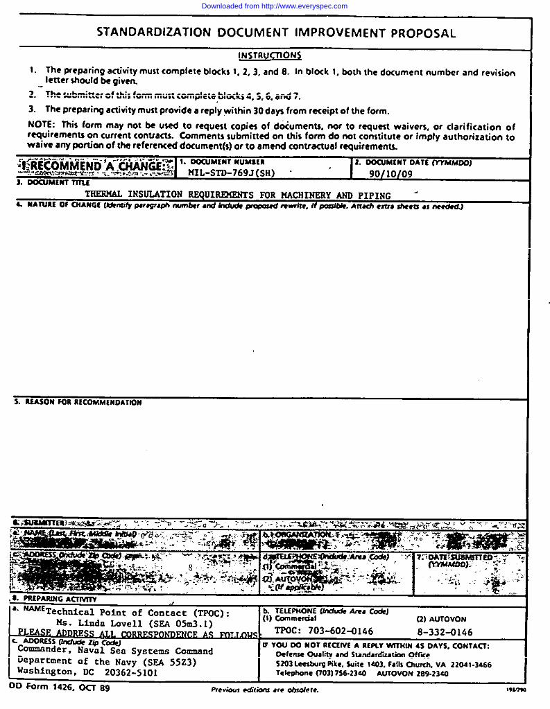
STANDARDIZATION DOCUMENT IMPROVEMENT PROPOSAL
lNSTRUCTfON~
1. The preparing am”vity mu$t complete blocki 1, 2.3, and 8. In blork 1. both [he document number and revisionletter $hould be given.
2. ‘“llw submitter of this fomrmust complete bfocks 4. S, 6. and 7.
3. The preparing artivity must provide a repiy within 30 days from receipt of the form.
NOTE: This form may not be used to request copies of dtiuments, nor to request waivers. or clarification ofrequirements on current contracts. Comments wbmitted on this form do not constitute or imply authorization towaive any portion of the refere~arj dorument(Q or to amend contractual requirements..
--$ -., -1 :,---- 1. OOCUMtHl NIJM1lR:l”<iiEC’O’MM-EN D A .CHIUKE:$ti
1 OOCUMIN1 OATE fYYAtAfOOJ
-V.---e.l’x z. .-.. S.- --- ...s UIL-STD-769J (SH) . ‘1. -MINT n7Ls
ITi52WW INSULATIONRSQUIRENZNTS FUR NACHINSRY AND PIPING -L SSA7UREOf CNANGfftinsify pwqraph number ●d 6nchd ~ #mwifr, S#po@bSt. Aftuh ●ma ahrcd ● neddJ
ciEua3m’7Eabrik+a.r:+-d ‘., -, ‘:y.? - -.~-:o :>-, >.- .;, ~.::.,..7 xgM,=yq*.~~;.#/& .~~.pa?c;~: u ; -T ‘+-:’WS
%@a&ii&isi%52w5 m<5%l!iEi”mF 7noAlEamMsTfeD--- .:
y’yy,. :,;’ .?,
.t PSEPAR132GA~
●. ~ET,ecb~cal pointof Contact(TPOC): h 7ELEPNONE Unduda Ara CodrJ
Ms. Linda Lovell (52A 05M3.1)(1)Com.emial
PLEASE ADDRE~ AS s? TPs3C:703-602-0146
~AjoN.,@,
8-332-0146c ADORESSflllrk&z~c-Commander, Naval Sea Systems Command
IFYOU 00 NOT RKSfVE A R[PLVW1’7t41N45 DAYS. CONTAIX
Department of the Navy (SEA 5523)Oefenla Quality ●nd slmld*?diz,riOrl w~e5203 Leabuw Fike. SuiCe1403. falls OIwrtl. VA 22041.3466
Iiashfngton, DC 20362-5101 Tele@wne f703) 7sa.23ao ALSTOVONz4g.z3a4
oo Form 1426. ocz 89 Previ.xl, C.jikntl ,,,? 0t1502ere. ,*I,7!
Downloaded from http://www.everyspec.com