note: for your convenience, this document identifies web ... · pdf fileautonomous ground...
TRANSCRIPT


Note: For your convenience, this document identifies Web links when available. These links are correct as of this publishing; however, since Web links can be moved or disconnected at any time, we have also provided source information as available to assist you in locating the information.

Contents
Timeline for NASA Student Launch .............................................................................................................. 1Acronym Dictionary ...................................................................................................................................... 2
Proposal/Statement of Work for Colleges/Universities/Non-Academic Teams
Design, Development, and Launch of a Reusable Rocket and Autonomous Ground Support Equipment (AGSE) Statement of Work (SOW) ................................................................. 4
Vehicle Requirements ............................................................................................................................ 5Recovery System Requirements ........................................................................................................... 7Competition and Autonomous Ground Support Equipment (AGSE) Requirements .............................. 8Safety Requirements ............................................................................................................................11General Requirements ......................................................................................................................... 12
Proposal Requirements ............................................................................................................................. 13
Proposal/Statement of Work for Middle/High Schools
Design, Development, and Launch of a Reusable Rocket and Payload Statement of Work (SOW) ......... 18Vehicle Requirements .......................................................................................................................... 18Recovery System Requirements ......................................................................................................... 20Payload Requirements ........................................................................................................................ 21Safety Requirements ........................................................................................................................... 22General Requirements ........................................................................................................................ 23
Proposal Requirements ............................................................................................................................. 24
Vehicle/Payload Criteria
Preliminary Design Review (PDR) Vehicle and AGSE/Payload Experiment Criteria ................................. 28Critical Design Review (CDR) Vehicle and AGSE/Payload Experiment Criteria ........................................ 32Flight Readiness Review (FRR) Vehicle and AGSE/Payload Experiment Criteria .................................... 37Launch Readiness Review (LRR) Vehicle and AGSE/Payload Experiment Criteria .................................. 42Post Launch Assessment Review (PLAR) Vehicle and AGSE/Payload Experiment Criteria ..................... 42Educational Engagement Form ................................................................................................................. 43
Safety
High Power Rocket Safety Code ............................................................................................................... 46Minimum Distance Table ............................................................................................................................ 48
Related Documents
NASA Project Life Cycle ............................................................................................................................ 50Hazard Analysis – Introduction to Managing Risk ....................................................................................... 61Example Hazard Analysis .......................................................................................................................... 71Understanding Material Safety Data Sheets (MSDS) ................................................................................ 77


Timeline for NASA Student Launch (Dates are subject to change.)
September 2014 11 Request for Proposal (RFP) goes out to all teams.
October 2014
6 Electronic copy of completed proposal due to project office by 5 p.m. CDT to
Ian Bryant (Jacobs ESSSA Group) [email protected]
Katie Wallace: [email protected]
Julie Clift: [email protected]
17 Awarded proposals announced 31 Team web presence established
November 2014 5 Preliminary Design Review (PDR) reports, presentation slides, and flysheet posted on the team Website by
8:00 a.m. Central Time. 7-21 PDR video teleconferences
January 2015: 16 Critical Design Review (CDR) reports, presentation slides, and flysheet posted on the team Website by
8:00 a.m. Central Time. 21-31 CDR video teleconferences
February 2015 1-4 CDR video teleconferences
March 2015: 16 Flight Readiness Review (FRR) reports, presentation slides, and flysheet posted to team Website by
8:00 a.m. Central Time. 18-27 FRR video teleconferences
April 2015: 7 Teams travel to Huntsville, AL 7 Launch Readiness Reviews (LRR) 8 LRR’s and safety briefing 9 Rocket Fair and Tours of MSFC 10 Mini/Maxi MAV Launch day, Banquet 11 Middle/High School Launch Day 12 Backup launch day 29 Post-Launch Assessment Review (PLAR) posted on the team Website by 8:00 a.m. Central Time.
May 2015: 11 Winning team announced
1
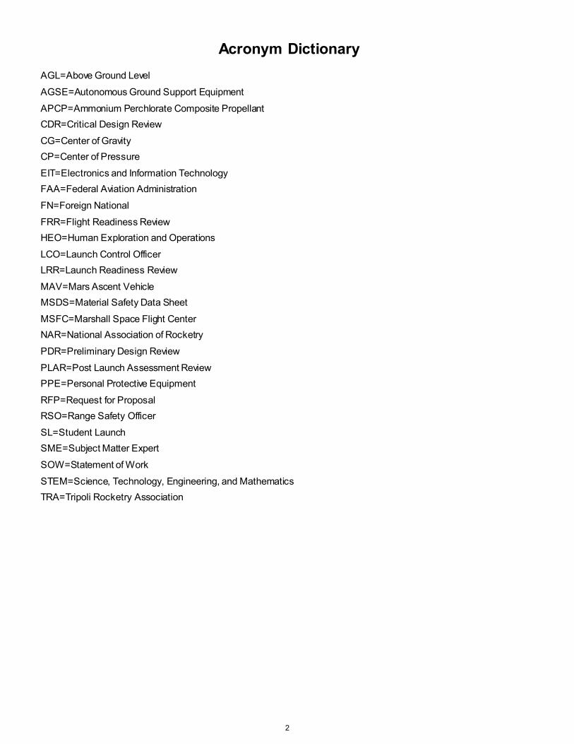
Acronym Dictionary
AGL=Above Ground Level
AGSE=Autonomous Ground Support Equipment
APCP=Ammonium Perchlorate Composite Propellant CDR=Critical Design Review
CG=Center of Gravity CP=Center of Pressure
EIT=Electronics and Information Technology FAA=Federal Aviation Administration
FN=Foreign National
FRR=Flight Readiness Review HEO=Human Exploration and Operations
LCO=Launch Control Officer LRR=Launch Readiness Review
MAV=Mars Ascent Vehicle MSDS=Material Safety Data Sheet
MSFC=Marshall Space Flight Center NAR=National Association of Rocketry
PDR=Preliminary Design Review
PLAR=Post Launch Assessment Review PPE=Personal Protective Equipment
RFP=Request for Proposal RSO=Range Safety Officer
SL=Student Launch SME=Subject Matter Expert
SOW=Statement of Work
STEM=Science, Technology, Engineering, and Mathematics TRA=Tripoli Rocketry Association
2

Proposal/Statement of Work for Colleges/Universities/
Non-Academic Teams
Design, Development, and Launch of a Reusable Rocket and Autonomous Ground Support Equipment Statement of Work
(SOW)
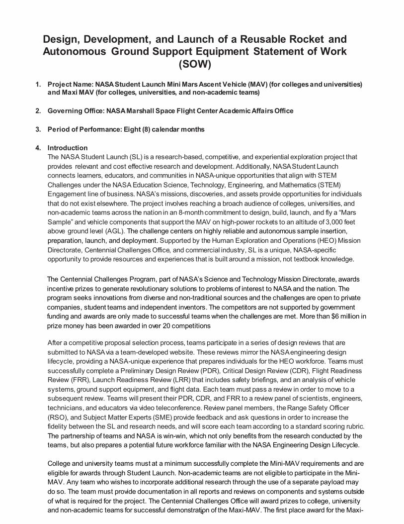
1. Project Name: NASA Student Launch Mini Mars Ascent Vehicle (MAV) (for colleges and universities) and Maxi MAV (for colleges, universities, and non-academic teams)
2. Governing Office: NASA Marshall Space Flight Center Academic Affairs Office
3. Period of Performance: Eight (8) calendar months
4. Introduction
The NASA Student Launch (SL) is a research-based, competitive, and experiential exploration project that provides relevant and cost effective research and development. Additionally, NASA Student Launch connects learners, educators, and communities in NASA-unique opportunities that align with STEM Challenges under the NASA Education Science, Technology, Engineering, and Mathematics (STEM) Engagement line of business. NASA’s missions, discoveries, and assets provide opportunities for individuals that do not exist elsewhere. The project involves reaching a broach audience of colleges, universities, and non-academic teams across the nation in an 8-month commitment to design, build, launch, and fly a “Mars Sample” and vehicle components that support the MAV on high-power rockets to an altitude of 3,000 feet above ground level (AGL). The challenge centers on highly reliable and autonomous sample insertion, preparation, launch, and deployment. Supported by the Human Exploration and Operations (HEO) Mission Directorate, Centennial Challenges Office, and commercial industry, SL is a unique, NASA-specific opportunity to provide resources and experiences that is built around a mission, not textbook knowledge.
The Centennial Challenges Program, part of NASA’s Science and Technology Mission Directorate, awards incentive prizes to generate revolutionary solutions to problems of interest to NASA and the nation. The program seeks innovations from diverse and non-traditional sources and the challenges are open to private companies, student teams and independent inventors. The competitors are not supported by government funding and awards are only made to successful teams when the challenges are met. More than $6 million in prize money has been awarded in over 20 competitions
After a competitive proposal selection process, teams participate in a series of design reviews that are submitted to NASA via a team-developed website. These reviews mirror the NASA engineering design lifecycle, providing a NASA-unique experience that prepares individuals for the HEO workforce. Teams must successfully complete a Preliminary Design Review (PDR), Critical Design Review (CDR), Flight Readiness Review (FRR), Launch Readiness Review (LRR) that includes safety briefings, and an analysis of vehicle systems, ground support equipment, and flight data. Each team must pass a review in order to move to a subsequent review. Teams will present their PDR, CDR, and FRR to a review panel of scientists, engineers, technicians, and educators via video teleconference. Review panel members, the Range Safety Officer (RSO), and Subject Matter Experts (SME) provide feedback and ask questions in order to increase the fidelity between the SL and research needs, and will score each team according to a standard scoring rubric. The partnership of teams and NASA is win-win, which not only benefits from the research conducted by the teams, but also prepares a potential future workforce familiar with the NASA Engineering Design Lifecycle. College and university teams must at a minimum successfully complete the Mini-MAV requirements and are eligible for awards through Student Launch. Non-academic teams are not eligible to participate in the Mini-MAV. Any team who wishes to incorporate additional research through the use of a separate payload may do so. The team must provide documentation in all reports and reviews on components and systems outside of what is required for the project. The Centennial Challenges Office will award prizes to college, university and non-academic teams for successful demonstration of the Maxi-MAV. The first place award for the Maxi-4

MAV is $25,000, the second place team receives $15,000, and the third place team receives $10,000. Maxi-MAV teams will only be eligible for prize money after the successful completion of all parts of the Maxi-MAV competition. The awards listed on pages 50-51 will only be given to Mini/Maxi teams from an academic institution.
The performance targets for the reusable launch vehicle, AGSE, and payload are
1. Vehicle Requirements
1.1. The vehicle shall deliver the payload to, but not exceeding, an apogee altitude of 3,000 feet above ground level (AGL).
1.2. The vehicle shall carry one commercially available, barometric altimeter for recording the official altitude used in the competition scoring. The altitude score will account for 10% of the team’s overall competition score. Teams will receive the maximum number of altitude points (3,000) by fully reaching the 3,000 feet AGL mark. For every foot of deviation above or below the target altitude, the team will lose 1 altitude point. The team’s altitude points will be divided by 3,000 to determine the altitude score for the competition.
1.2.1.The official scoring altimeter shall report the official competition altitude via a series of beeps to be checked after the competition flight.
1.2.2.Teams may have additional altimeters to control vehicle electronics and payload experiment(s).
1.2.2.1. At the Launch Readiness Review, a NASA official will mark the altimeter that will be used for the official scoring.
1.2.2.2. At the launch field, a NASA official will obtain the altitude by listening to the audible beeps reported by the official competition, marked altimeter.
1.2.2.3. At the launch field, to aid in determination of the vehicle’s apogee, all audible electronics, except for the official altitude-determining altimeter shall be capable of being turned off.
1.2.3.The following circumstances will warrant a score of zero for the altitude portion of the
competition: 1.2.3.1. The official, marked altimeter is damaged and/or does not report an altitude via a series
of beeps after the team’s competition flight. 1.2.3.2. The team does not report to the NASA official designated to record the altitude with their
official, marked altimeter on the day of the launch. 1.2.3.3. The altimeter reports an apogee altitude over 5,000 feet AGL. 1.2.3.4. The rocket is not flown at the competition launch site.
1.3. The launch vehicle shall be designed to be recoverable and reusable. Reusable is defined as being
able to launch again on the same day without repairs or modifications. 1.4. The launch vehicle shall have a maximum of four (4) independent sections. An independent section is
defined as a section that is either tethered to the main vehicle or is recovered separately from the main vehicle using its own parachute.
1.5. The launch vehicle shall be limited to a single stage. 1.6. The launch vehicle shall be capable of being prepared for flight at the launch site within 2 hours, from
the time the Federal Aviation Administration flight waiver opens. 1.7. The launch vehicle shall be capable of remaining in launch-ready configuration at the pad for a
minimum of 1 hour without losing the functionality of any critical on-board component. 1.8. The launch vehicle shall be capable of being launched by a standard 12 volt direct current firing system.
The firing system will be provided by the NASA-designated Range Services Provider.
1.9. The launch vehicle shall use a commercially available solid motor propulsion system using ammonium perchlorate composite propellant (APCP) which is approved and certified by the National Association of Rocketry (NAR), Tripoli Rocketry Association (TRA), and/or the Canadian Association of Rocketry (CAR). 1.9.1.Final motor choices must be made by the Critical Design Review (CDR).
5

1.9.2.Any motor changes after CDR must be approved by the NASA Range Safety Officer (RSO), and will only be approved if the change is for the sole purpose of increasing the safety margin.
1.10. The total impulse provided by a launch vehicle shall not exceed 5,120 Newton-seconds (L-class). 1.11. Any team participating in Maxi-MAV will be required to provide an inert or replicated version of their
motor matching in both size and weight to their launch day motor. This motor will be used during the LRR to ensure the igniter installer will work with the competition motor on launch day.
1.12. Pressure vessels on the vehicle shall be approved by the RSO and shall meet the following criteria: 1.12.1. The minimum factor of safety (Burst or Ultimate pressure versus Max Expected Operating
Pressure) shall be 4:1 with supporting design documentation included in all milestone reviews. 1.12.2. The low-cycle fatigue life shall be a minimum of 4:1. 1.12.3. Each pressure vessel shall include a solenoid pressure relief valve that sees the full
pressure of the tank. 1.12.4. Full pedigree of the tank shall be described, including the application for which the tank was
designed, and the history of the tank, including the number of pressure cycles put on the tank, by whom, and when.
1.13. All teams shall successfully launch and recover a subscale model of their full-scale rocket prior to CDR.
The subscale model should resemble and perform as similarly as possible to the full-scale model, however, the full-scale shall not be used as the subscale model.
1.14. All teams shall successfully launch and recover their full-scale rocket prior to FRR in its final flight
configuration. The rocket flown at FRR must be the same rocket to be flown on launch day. The purpose of the full-scale demonstration flight is to demonstrate the launch vehicle’s stability, structural integrity, recovery systems, and the team’s ability to prepare the launch vehicle for flight. A successful flight is defined as a launch in which all hardware is functioning properly (i.e. drogue chute at apogee, main chute at a lower altitude, functioning tracking devices, etc.). The following criteria must be met during the full scale demonstration flight:
1.14.1. The vehicle and recovery system shall have functioned as designed. 1.14.2. The payload does not have to be flown during the full-scale test flight. The following
requirements still apply: 1.14.2.1. If the payload is not flown, mass simulators shall be used to simulate the payload mass. 1.14.2.2. The mass simulators shall be located in the same approximate location on the rocket as
the missing payload mass. 1.14.2.3. If the payload changes the external surfaces of the rocket (such as with camera housings
or external probes) or manages the total energy of the vehicle, those systems shall be active during the full-scale demonstration flight.
1.14.3. The full-scale motor does not have to be flown during the full-scale test flight. However, it is
recommended that the full-scale motor be used to demonstrate full flight readiness and altitude verification. If the full-scale motor is not flown during the full-scale flight, it is desired that the motor simulate, as closely as possible, the predicted maximum velocity and maximum acceleration of the competition flight.
1.14.4. The vehicle shall be flown in its fully ballasted configuration during the full-scale test flight. Fully
ballasted refers to the same amount of ballast that will be flown during the competition flight.
1.14.5. After successfully completing the full-scale demonstration flight, the launch vehicle or any of its components shall not be modified without the concurrence of the NASA Range Safety Officer (RSO).
1.15. Each team will have a maximum budget they may spend on the rocket and the Autonomous Ground
Support Equipment (AGSE). Teams who are participating in the Maxi-MAV competition are limited to a $10,000 budget while teams participating in Mini-MAV are limited to $5,000. The cost is for the
6
competition rocket and AGSE as it sits on the pad, including all purchased components. The fair market value of all donated items or materials shall be included in the cost analysis. The following items may be omitted from the total cost of the vehicle:
• Shipping costs • Team labor costs
1.16. Vehicle Prohibitions 1.16.1. The launch vehicle shall not utilize forward canards. 1.16.2. The launch vehicle shall not utilize forward firing motors. 1.16.3. The launch vehicle shall not utilize motors that expel titanium sponges (Sparky,
Skidmark, MetalStorm, etc.). 1.16.4. The launch vehicle shall not utilize hybrid motors. 1.16.5. The launch vehicle shall not utilize a cluster of motors.
2. Recovery System Requirements
2.1. The launch vehicle shall stage the deployment of its recovery devices, where a drogue parachute is deployed at apogee and a main parachute is deployed at a much lower altitude. Tumble recovery or streamer recovery from apogee to main parachute deployment is also permissible, provided the kinetic energy during drogue-stage descent is reasonable, as deemed by the Range Safety Officer.
2.2. Teams must perform a successful ground ejection test for both the drogue and main parachutes. This
must be done prior to the initial subscale and full scale launches.
2.3. At landing, each independent section of the launch vehicle shall have a maximum kinetic energy of 75 ft-lbf.
2.4. The recovery system electrical circuits shall be completely independent of any payload electrical
circuits.
2.5. The recovery system shall contain redundant, commercially available altimeters. The term “altimeters” includes both simple altimeters and more sophisticated flight computers. One of these altimeters may be chosen as the competition altimeter.
2.6. A dedicated arming switch shall arm each altimeter, which is accessible from the exterior of the rocket
airframe when the rocket is in the launch configuration on the launch pad.
2.7. Each altimeter shall have a dedicated power supply.
2.8. Each arming switch shall be capable of being locked in the ON position for launch.
2.9. Removable shear pins shall be used for both the main parachute compartment and the drogue parachute compartment.
2.10. An electronic tracking device shall be installed in the launch vehicle and shall transmit the position of
the tethered vehicle or any independent section to a ground receiver. 2.10.1. Any rocket section, or payload component, which lands untethered to the launch vehicle shall
also carry an active electronic tracking device. 2.10.2. The electronic tracking device shall be fully functional during the official flight at the competition
launch site.
7

2.11. The recovery system electronics shall not be adversely affected by any other on-board electronic devices during flight (from launch until landing).
2.11.1. The recovery system altimeters shall be physically located in a separate compartment within the vehicle from any other radio frequency transmitting device and/or magnetic wave producing device.
2.11.2. The recovery system electronics shall be shielded from all onboard transmitting devices, to avoid inadvertent excitation of the recovery system electronics.
2.11.3. The recovery system electronics shall be shielded from all onboard devices which may generate magnetic waves (such as generators, solenoid valves, and Tesla coils) to avoid inadvertent excitation of the recovery system.
2.11.4. The recovery system electronics shall be shielded from any other onboard devices which may adversely affect the proper operation of the recovery system electronics.
3. Competition and Autonomous Ground Support Equipment (AGSE) Requirements
There are two challenges in which teams may compete, Mini-MAV or Maxi-MAV. At a minimum, each college or university team shall participate in the Mini-MAV challenge with the option to participate in the Maxi-MAV/Centennial Challenge. Non-academic teams are not permitted to compete in the Mini-MAV challenge. The structure and requirements for each MAV challenge are detailed as follows.
3.1. Mini-MAV.
3.1.1.The Mini-MAV will introduce the team participants to autonomous systems with partial human intervention. Teams will be required to capture and contain a payload, launch it, and eject it during the launch vehicle’s descent. On launch day, each launch will follow this general procedure.
3.1.1.1. Teams will position their launch vehicle horizontally or vertically on the launch pad. 3.1.1.2. A master switch will be activated to power on all autonomous procedures and subroutines. 3.1.1.3. After the master switch is turned on and all systems are booted, a pause switch will be
activated, temporarily halting all AGSE procedure and subroutines. This will allow the other teams at the pads to set up, and do the same.
3.1.1.4. After setup, one judge, one launch services official, and the team will remain at the pad. During autonomous procedures, the team is not permitted to interact with their AGSE.
3.1.1.5. After all nonessential personnel have evacuated, the pause switch will be deactivated. 3.1.1.6. Once the pause switch is deactivated, the AGSE will capture and contain the payload within
the launch vehicle. If the launch vehicle is in a horizontal position, the launch platform will then be manually erected by the team to an angle of 5 degrees off vertical, pointed away from the spectators. The launch services official may re-enable the pause switch at any time at his/her discretion for safety concerns.
3.1.1.7. After the erection of the launch vehicle, a team member will arm recovery electronics. 3.1.1.8. The igniter is manually installed and the area is evacuated. 3.1.1.9. Once the launch services official has inspected the launch vehicle and declares that the
system is eligible for launch, he/she will activate a master arming switch to enable ignition procedures.
3.1.1.10. The Launch Control Officer (LCO) will activate a hard switch, and then provide a 5-second countdown.
3.1.1.11. At the end of the countdown, the LCO will push the final launch button, initiating launch. 3.1.1.12. The rocket will launch as designed and jettison the payload at 1,000 feet AGL during
descent.
3.1.2.The Autonomous Ground Support Equipment (AGSE) 3.1.2.1. For the purpose of this challenge, ASGE is defined as all mechanical and electrical
components not part of the launch vehicle, and is provided by the teams. Components may include the payload containment device, computers, batteries, etc.
3.1.2.2. The payload containment system shall be fully autonomous with no human intervention. 3.1.2.3. Any pressure vessel used in the AGSE will follow all regulations set by requirement 1.12 in the
Vehicle Requirements section. 8

3.1.3.Prohibited Technology for AGSE 3.1.3.1. As one of the goals of this competition is to develop equipment, processes, and technologies
that could be implemented in a Martian environment, the AGSE and any related technology cannot employ processes that would not work in such environments. Therefore, prohibited technologies include:
3.1.3.1.1. Sensors that rely on Earth’s magnetic field 3.1.3.1.2. Ultrasonic or other sound-based sensors 3.1.3.1.3. Earth-based or Earth orbit-based radio aids (e.g. GPS, VOR, cell phone). 3.1.3.1.4. Open circuit pneumatics 3.1.3.1.5. Air breathing systems
3.1.4.Payload 3.1.4.1. Each launch vehicle must have the space to contain a cylindrical payload approximately 3/4
inch in diameter and 4.75 inches in length. The payload will be made of ¾ x 3 inch PVC tubing filled with sand and weighing approximately 4 oz., and capped with domed PVC end caps. Each launch vehicle must be able to seal the payload containment area autonomously prior to launch.
3.1.4.2. Teams may construct their own payload according to the above specifications, however, each team will be required to use a regulation payload provided to them on launch day.
3.1.4.3. The payload will not contain any hooks or other means to grab it. A diagram of the payload and a sample payload will be provided to each team at time of acceptance into the competition.
3.1.4.4. The payload may be placed anywhere in the launch area for insertion, as long as it is outside the mold line of the launch vehicle when placed in the horizontal or vertical position on the AGSE.
3.1.4.5. The payload container must utilize a parachute for recovery and contain a GPS or radio locator.
3.1.5.Safety and AGSE Control 3.1.5.1. Each team must provide the following switches and indicators for their AGSE to be used by
the LCO/RSO. 3.1.5.1.1. A master switch to power all parts of the AGSE. The switch must be easily accessible
and hardwired to the AGSE. 3.1.5.1.2. A pause switch to temporarily terminate all actions performed by AGSE. The switch
must be easily accessible and hardwired to the AGSE. 3.1.5.1.3. A safety light that indicates that the AGSE power is turned on. The light must be
amber/orange in color. It will flash at a frequency of 1 Hz when the AGSE is powered on, and will be solid in color when the AGSE is paused while power is still supplied.
3.2. Maxi-MAV. 3.2.1.The Maxi-MAV will provide each team with the opportunity to develop a unique method to capture,
contain, launch, and eject a payload with limited human intervention. In addition, teams will develop a launch system that erects a rocket from a horizontal to vertical position, and has its igniter autonomously installed. On launch day, each launch will follow this general procedure.
3.2.1.1. Teams will position their launch vehicle horizontally on the AGSE. 3.2.1.2. A master switch will be activated to power on all autonomous procedures and subroutines. 3.2.1.3. After the master switch is turned on, a pause switch will be activated, temporarily halting all
AGSE procedure and subroutines. This will allow the other teams at the pads to set up, and do the same.
3.2.1.4. After setup, one judge, one launch services official, and one member of the team will remain at the pad. The rest of the team must evacuate the area. The one team member is only there to answer questions the launch services official may have, and is not permitted to interact with the AGSE in any way.
3.2.1.5. After all nonessential personnel have evacuated, the pause switch will be deactivated.
9

3.2.1.6. Once the pause switch is deactivated, the AGSE will progress through all subroutines starting with the capture and containment of the payload, then erection of the launch platform, and lastly the insertion of the motor igniter. The launch platform must be erected to an angle of 5 degrees off vertical pointed away from the spectators. The launch services official may re-enable the pause switch at any time at his/her discretion. If the pause switch is re-enabled all systems and actions shall cease immediately. The launch services official will only do this if there is an obvious safety hazard. The judge, launch services official, and team leader will meet to discuss and decide if the team will be allowed to do a reset and rerun of their attempt. No modifications to the hardware will be allowed prior to a rerun.
3.2.1.7. The one team member will arm all recovery electronics. 3.2.1.8. Once the launch services official has inspected the launch vehicle and declares that the
system is eligible for launch, he/she will activate a master arming switch to enable ignition procedures.
3.2.1.9. All personnel at the launch pad will evacuate the area. 3.2.1.10. The Launch Control Officer (LCO) will activate a hard switch, and then provide a 5-second
countdown. 3.2.1.11. At the end of the countdown, the LCO will push the final launch button to initiate launch. 3.2.1.12. The rocket will launch as designed and jettison the payload at 1,000 feet AGL during
descent.
3.2.2.The Autonomous Ground Support Equipment (AGSE) 3.2.2.1. For the purpose of this challenge, ASGE is defined as all mechanical and electrical
components not part of the launch vehicle, and is provided by the teams. This includes, but is not limited to, the payload containment and igniter installation devices, computers, electric motors, batteries, etc.
3.2.2.2. All AGSE systems shall be fully autonomous. The only human interaction will be when the launch services official pauses or arms any equipment, when the team arms the recovery electronics, and when the LCO initiates launch.
3.2.2.3. Any pressure vessel used in the AGSE will follow all regulations set by requirement 1.12 in the Vehicle Requirements section.
3.2.3.Prohibited Technology for AGSE
3.2.3.1. As one of the goals of this competition is to develop equipment, processes, and technologies that could be implemented in a Martian environment, the AGSE and any related technology cannot employ processes that would not work in such environments. Therefore, prohibited technologies include:
3.2.3.1.1. Sensors that rely on Earth’s magnetic field 3.2.3.1.2. Ultrasonic or other sound-based sensors 3.2.3.1.3. Earth-based or Earth orbit-based radio aids (e.g. GPS, VOR, cell phone). 3.2.3.1.4. Open circuit pneumatics 3.2.3.1.5. Air breathing systems
3.2.4.Payload
3.2.4.1. Each launch vehicle must have the space to contain a cylindrical payload approximately 3/4 inch in diameter and 4.75 inches in length. The payload will be made of ¾ x 3 inch PVC tubing filled with sand and weighing approximately 4 oz., and capped with domed PVC end caps. Each launch vehicle must be able to seal the payload containment area autonomously prior to launch.
3.2.4.2. Teams may construct their own payload according to the above specifications, however, each team will be required to use a regulation payload provided to them on launch day.
3.2.4.3. The payload will not contain any hooks or other means to grab it. A diagram of the payload and a sample payload will be provided to each team at time of acceptance into the competition.
3.2.4.4. The payload may be placed anywhere in the launch area for insertion, as long as it is outside the mold line of the launch vehicle when placed in the horizontal position on the AGSE.
3.2.4.5. The payload container must utilize a parachute for recovery and contain a GPS or radio locator. 10

3.2.4.6. Each team will be given 10 minutes to autonomously capture, place, and seal the payload within their rocket, and erect the rocket to a vertical launch position five degrees off vertical. Insertion of igniter and activation for launch are also included in this time. Going over time will result in the team’s disqualification from the Maxi-MAV competition.
3.2.5.Safety and AGSE Control
3.2.5.1. Each team must provide the following switches and indicators for their AGSE to be used by the LCO/RSO.
3.2.5.1.1. A master switch to power all parts of the AGSE. The switch must be easily accessible and hardwired to the AGSE.
3.2.5.1.2. A pause switch to temporarily terminate all actions performed by AGSE. The switch must be easily accessible and hardwired to the AGSE.
3.2.5.1.3. A safety light that indicates that the AGSE power is turned on. The light must be amber/orange in color. It will flash at a frequency of 1 Hz when the AGSE is powered on, and will be solid in color when the AGSE is paused while power is still supplied.
3.2.5.1.4. An all systems go light to verify all systems have passed safety verifications and the rocket system is ready to launch.
3.2.6.Failure of the Maxi-MAV
3.2.6.1. Any team who fails to complete any of the procedures in requirement 3.2 will be ineligible of obtaining Centennial Challenges prizes.
4. Safety Requirements
4.1. Each team shall use a launch and safety checklist. The final checklists shall be included in the FRR report and used during the Launch Readiness Review (LRR) and launch day operations.
4.2. For all academic institution teams, a student safety officer shall be identified, and shall be responsible for
all items in section 4.3. For competing, non-academic teams, one participant who is not serving in the team mentor role shall serve as the designated safety officer.
4.3. The role and responsibilities of each safety officer shall include but not limited to:
4.3.1.Monitor team activities with an emphasis on Safety during: 4.3.1.1. Design of vehicle and launcher 4.3.1.2. Construction of vehicle and launcher 4.3.1.3. Assembly of vehicle and launcher 4.3.1.4. Ground testing of vehicle and launcher 4.3.1.5. Sub-scale launch test(s) 4.3.1.6. Full-scale launch test(s) 4.3.1.7. Competition launch 4.3.1.8. Recovery activities 4.3.1.9. Educational Engagement activities
4.3.2.Implement procedures developed by the team for construction, assembly, launch, and recovery activities.
4.3.3.Manage and maintain current revisions of the team’s hazard analyses, failure modes analyses, procedures, and MSDS/chemical inventory data.
4.3.4.Assist in the writing and development of the team’s hazard analyses, failure modes analyses, and procedures.
4.4. Each team shall identify a “mentor.” A mentor is defined as an adult who is included as a team member, who will be supporting the team (or multiple teams) throughout the project year, and may or may not be affiliated with the school, institution, or organization. The mentor shall be certified by the National Association of Rocketry (NAR) or Tripoli Rocketry Association (TRA) for the motor impulse of the launch vehicle, and the rocketeer shall have flown and successfully recovered (using electronic, staged recovery) a minimum of 2 flights in this or a higher impulse class, prior to PDR. The mentor is designated as the individual owner of the rocket for liability purposes and must travel with the team to
11

the launch at the competition launch site. One travel stipend will be provided per mentor regardless of the number of teams he or she supports. The stipend will only be provided if the team passes FRR and the team and mentor attend launch week in April.
4.5. During test flights, teams shall abide by the rules and guidance of the local rocketry club’s RSO. The allowance of certain vehicle configurations and/or payloads at the NASA Student Launch and/or Centennial Challenges competition launch does not give explicit or implicit authority for teams to fly those certain vehicle configurations and/or payloads at other club launches. Teams should communicate their intentions to the local club’s President or Prefect and RSO before attending any NAR or TRA launch.
4.6. Teams shall abide by all rules and regulations set forth by the FAA.
5. General Requirements
5.1. Team members (students if the team is from an academic institution) shall do 100% of the project, including design, construction, written reports, presentations, and flight preparation. The one exception deals with the handling of black powder, ejection charges, and installing electric matches. These tasks shall be performed by the team’s mentor, regardless if the team is from an academic institution or not.
5.2. The team shall provide and maintain a project plan to include, but not limited to the following items:
project milestones, budget and community support, checklists, personnel assigned, educational engagement events, and risks and mitigations.
5.3. Each team shall successfully complete and pass a review in order to move onto the next phase of
the competition.
5.4. Foreign National (FN) team members shall be identified by the Preliminary Design Review (PDR) and may or may not have access to certain activities during launch week due to security restrictions. In addition, FN’s may be separated from their team during these activities. If participating in the Maxi-MAV, less than 50% of the team make-up may be foreign nationals.
5.5. The team shall identify all team members attending launch week activities by the Critical Design
Review (CDR). Team members shall include: 5.5.1.For academic institutions, students actively engaged in the project throughout the entirety of the
project lifespan and currently enrolled in the proposing institution. 5.5.2.For non-academic teams, participants actively engaged in the project who will remain affiliated with
the team for the entirety of the project lifespan. The Team Lead, Team Mentor, and team Safety Officer shall be noted on the team roster. Team members may hold multiple positions.
5.5.3.One mentor (see requirement 4.4). 5.5.4.No more than two adult educators per academic team.
5.6. The team shall engage a minimum of 200 participants (at least 100 of those shall be middle school
students or educators) in educational, hands-on science, technology, engineering, and mathematics (STEM) activities, as defined in the Educational Engagement form, by FRR. An educational engagement form shall be completed and submitted within two weeks after completion of each event. A sample of the educational engagement form can be found on page 45 of the handbook.
5.7. The team shall develop and host a Website for project documentation.
5.8. Teams shall post, and make available for download, the required deliverables to the team Web site by
the due dates specified in the project timeline.
12

5.9. All deliverables must be in PDF format.
5.10. In every report, teams shall provide a table of contents including major sections and their respective sub-sections.
5.11. In every report, the team shall include the page number at the bottom of the page.
5.12. The team shall provide any computer equipment necessary to perform a video teleconference with the
review board. This includes, but not limited to, computer system, video camera, speaker telephone, and a broadband Internet connection. If possible, the team shall refrain from use of cellular phones as a means of speakerphone capability.
5.13. Teams must implement the Architectural and Transportation Barriers Compliance Board Electronic
and Information Technology (EIT) Accessibility Standards (36 CFR Part 1194) Subpart B-Technical Standards (http://www.section508.gov):
1194.21 Software applications and operating systems. 1194.22 Web-based intranet and Internet information and applications.
Proposal Requirements
At a minimum, the proposing team shall identify the following in a written proposal due to NASA MSFC by the dates specified in the project timeline.
General Information
1. A cover page that includes the name of the college/university or non-academic organization, mailing address,
title of the project, the date, and whether the team is participating in the Mini-MAV or Maxi-MAV portion of the competition.
2. Name, title, and contact information for up to two adult educators (for academic teams).
3. Name and title of the individual who will take responsibility for implementation of the safety plan. (Safety Officer)
4. Name, title, and contact information for the team leader.
5. Approximate number of participants who will be committed to the project and their proposed duties.
Include an outline of the project organization that identifies the key managers (participants and/or educator administrators) and the key technical personnel. Only use first names for identifying team members; do not include surnames. (See requirement 5.3 and 5.4 for definition of team members).
6. Name of the NAR/TRA section(s) the team is planning to work with for purposes of mentoring, review of
designs and documentation, and/or launch assistance. Facilities/Equipment 1. Description of facilities and hours of accessibility, necessary personnel, equipment, and supplies that
are required to design and build a rocket and the AGSE.
13

Safety The Federal Aviation Administration (FAA) [www.faa.gov] has specific laws governing the use of airspace. A demonstration of the understanding and intent to abide by the applicable federal laws (especially as related to the use of airspace at the launch sites and the use of combustible/ flammable material), safety codes, guidelines, and procedures for building, testing, and flying large model rockets is crucial. The procedures and safety regulations of the NAR [http://www.nar.org/safety.html] shall be used for flight design and operations. The NAR/TRA mentor and Safety Officer shall oversee launch operations and motor handling.
1. Provide a written safety plan addressing the safety of the materials used, facilities involved, and team
member responsible, i.e., Safety Officer, for ensuring that the plan is followed. A risk assessment should be done for all aspects in addition to proposed mitigations. Identification of risks to the successful completion of the project should be included.
1.1. Provide a description of the procedures for NAR/TRA personnel to perform. Ensure the following:
• Compliance with NAR high power safety code requirements [http://nar.org/NARhpsc.html].
• Performance of all hazardous materials handling and hazardous operations.
1.2. Describe the plan for briefing team members on hazard recognition and accident avoidance, and conducting pre-launch briefings.
1.3. Describe methods to include necessary caution statements in plans, procedures and other working
documents, including the use of proper Personal Protective Equipment (PPE).
1.4. Provide a plan for complying with federal, state, and local laws regarding unmanned rocket launches and motor handling. Specifically, regarding the use of airspace, Federal Aviation Regulations 14 CFR, Subchapter F, Part 101, Subpart C; Amateur Rockets, Code of Federal Regulation 27 Part 55: Commerce in Explosives; and fire prevention, NFPA 1127 “Code for High Power Rocket Motors.”
1.5. Provide a plan for NRA/TRA mentor purchase, storage, transport, and use of rocket motors and energetic
devices.
1.6. Provide a written statement that all team members understand and will abide by the following safety regulations:
1.6.1.Range safety inspections of each rocket before it is flown. Each team shall comply with the determination of the safety inspection or may be removed from the program.
1.6.2.The RSO has the final say on all rocket safety issues. Therefore, the RSO has the right to deny the launch of any rocket for safety reasons.
1.6.3.Any team that does not comply with the safety requirements will not be allowed to launch their rocket.
Technical Design 1. A proposed and detailed approach to rocket and payload design.
a. Include general vehicle dimensions, material selection and justification, and construction methods. b. Include projected altitude and describe how it was calculated. c. Include projected parachute system design. d. Include projected motor brand and designation. e. Include description of the team’s projected AGSE. f. Address the requirements for the vehicle, recovery system, and AGSE. g. Address major technical challenges and solutions.
14

Educational Engagement 1. Include plans and evaluation criteria for required educational engagement activities. (See requirement 5.5).
Project Plan 1. Provide a detailed development schedule/timeline covering all aspects necessary to successfully
complete the project. 2. Provide a detailed budget to cover all aspects necessary to successfully complete the project including
team travel to launch week. 3. Provide a detailed funding plan.
4. Provide a written plan for soliciting additional “community support,” which could include, but is not limited to,
expertise needed, additional equipment/supplies, sponsorship, services (such as free shipping for launch vehicle components, if required, advertisement of the event, etc.), or partnering with industry or other public or private schools.
5. Develop a clear plan for sustainability of the rocket project in the local area. This plan should include how to provide and maintain established partnerships and regularly engage successive teams in rocketry. It should also include partners (industry/community), recruitment of team members, funding sustainability, and educational engagement.
Prior to award, all proposing entities may be required to brief NASA representatives. The time and the place for the briefings will be determined by the NASA MSFC Academic Affairs Office.
Deliverables shall include: 1. A reusable rocket and required AGSE ready for the official launch.
2. A scale model of the rocket design with an AGSE prototype. This model should be flown prior to the CDR.
A report of the data from the flight and the model should be brought to the CDR. 3. Reports, PDF slideshows, and Milestone Review Flysheets due according to the provided timeline, and shall
be posted on the team Web site by the due date. (Dates are tentative at this point. Final dates will be announced at the time of award.)
4. The team(s) shall have a Web presence no later than the date specified. The Web site shall be maintained/
updated throughout the period of performance. 5. Electronic copies of the Educational Engagement form(s) and lessons learned pertaining to the implemented
educational engagement activities shall be submitted prior to the FRR and no later than two weeks after the educational engagement event.
The team shall participate in a PDR, CDR, FRR, LRR, and PLAR. (Dates are tentative and subject to change.)
The PDR, CDR, FRR, and LRR will be presented to NASA at a time and/or location to be determined by NASA MSFC Academic Affairs Office.
15


Proposal/Statement of Work for Middle/High Schools

Design, Development, and Launch of a Reusable Rocket and Payload Statement of Work (SOW)
1. Project Name: NASA Student Launch for Middle and High School
2. Governing Office: NASA Marshall Space Flight Center Academic Affairs Office
3. Period of Performance: Eight (8) calendar months.
4. Introduction
The Academic Affairs Office at the NASA Marshall space Flight Center (MSFC) will partner with middle school, high school, and informal organizations to sponsor the NASA Student Launch (SL) rocket and payload teams during the 2014-2015 academic year. This year’s NASA SL is designed to engage teams who have previously qualified and successfully completed SL as a first year team in 2012-2013 or teams who have qualified at the Team America Rocketry Challenge or Rockets For Schools competition in 2014 and have participated in the NASA Advanced Rocketry Workshop. A maximum of 2 teams from the same institution may be accepted. NASA SL provides a learning opportunity that involves design, construction, test, and launch of a reusable launch vehicle and science-related fields. Teaming with engineers from government, business, and academia, students get a hands-on, inside look at the science and engineering professions. SL requires an 8-month commitment to design, construct, test, launch, and successfully recover a reusable rocket and payload to an altitude of 5,280 feet above ground level (AGL). The initiative is more than designing and building a rocket from a commercial kit. It involves diverse aspects, such as the following: scheduling, purchasing, performing calculations, financing the project, coordinating logistics, educational engagement, Web site development, and documenting impact made on education through reports and design reviews. Each team must complete a Preliminary Design Review (PDR), Critical Design Review (CDR), Flight Readiness Review (FRR), Launch Readiness Review (LRR) that includes a safety briefing, and a Post Launch Analysis Review (PLAR) which contains an analysis of vehicle systems and flight data from the final flight.
The performance targets for the reusable launch vehicle and payload are
1. Vehicle Requirements
1.1. The vehicle shall deliver the science or engineering payload to, but not exceeding, an apogee altitude of 5,280 feet above ground level (AGL).
1.2. The launch vehicle shall be designed to be recoverable and reusable. Reusable is defined as
being able to launch again on the same day without repairs or modifications. 1.3. The launch vehicle shall have a maximum of four (4) independent sections. An independent
section is defined as a section that is either tethered to the main vehicle or is recovered separately from the main vehicle using its own parachute.
1.4. The launch vehicle shall be limited to a single stage.
1.5. The launch vehicle shall be capable of being prepared for flight at the launch site within 2 hours,
from the time the Federal Aviation Administration flight waiver opens.
18

1.6. The launch vehicle shall be capable of remaining in launch-ready configuration at the pad for a minimum of 1 hour without losing the functionality of any critical on-board component.
1.7. The launch vehicle shall be capable of being launched by a standard 12 volt direct current firing system. The firing system will be provided by the NASA-designated Range Services Provider.
1.8. The launch vehicle shall require no external circuitry or special ground support equipment to
initiate launch (other than what is provided by Range Services).
1.9. The launch vehicle shall use a commercially available solid motor propulsion system using ammonium perchlorate composite propellant (APCP) which is approved and certified by the National Association of Rocketry (NAR), Tripoli Rocketry Association (TRA), and/or the Canadian Association of Rocketry (CAR).
1.9.1. Final motor choices must be made by the Critical Design Review (CDR). 1.9.2. Any motor changes after CDR must be approved by the NASA Range Safety Officer (RSO),
and will only be approved if the change is for the sole purpose of increasing the safety margin.
1.10. Pressure vessels on the vehicle shall be approved by the RSO and shall meet the following criteria:
1.10.1. The minimum factor of safety (Burst or Ultimate pressure versus Max Expected Operating Pressure) shall be 4:1 with supporting design documentation included in all milestone reviews.
1.10.2. The low-cycle fatigue life shall be a minimum of 4:1. 1.10.3. Each pressure vessel shall include a solenoid pressure relief valve that sees the full
pressure of the tank. 1.10.4. Full pedigree of the tank shall be described, including the application for which the tank was
designed, and the history of the tank, including the number of pressure cycles put on the tank, by whom, and when.
1.11. The total impulse provided by a Middle and/or High School launch vehicle shall not exceed 2,560
Newton-seconds (K-class). 1.12. All teams shall successfully launch and recover a subscale model of their rocket prior to CDR. The
subscale model should resemble and perform as similarly as possible to the full-scale model, however, the full-scale shall not be used as the subscale model.
1.13. All teams shall successfully launch and recover their full-scale rocket prior to FRR in its final flight con-
figuration. The rocket flown at FRR must be the same rocket to be flown on launch day. The purpose of the full-scale demonstration flight is to demonstrate the launch vehicle’s stability, structural integrity, recovery systems, and the team’s ability to prepare the launch vehicle for flight. A successful flight is defined as a launch in which all hardware is functioning properly (i.e. drogue chute at apogee, main chute at a lower altitude, functioning tracking devices, etc.). The following criteria must be met during the full scale demonstration flight: 1.13.1. The vehicle and recovery system shall have functioned as designed.
19

1.13.2. The payload does not have to be flown during the full-scale test flight. The following requirements still apply: 1.13.2.1. If the payload is not flown, mass simulators shall be used to simulate the
payload mass. 1.13.2.1.1. The mass simulators shall be located in the same approximate location on the
rocket as the missing payload mass. 1.13.2.2. If the payload changes the external surfaces of the rocket (such as with
camera housings or external probes) or manages the total energy of the vehicle, those systems shall be active during the full-scale demonstration flight.
1.13.3. The full-scale motor does not have to be flown during the full-scale test flight. However, it is
recommended that the full-scale motor be used to demonstrate full flight readiness and altitude verification. If the full-scale motor is not flown during the full-scale flight, it is desired that the motor simulate, as closely as possible, the predicted maximum velocity and maximum acceleration of the launch day flight.
1.13.4. The vehicle shall be flown in its fully ballasted configuration during the full-scale test flight.
Fully ballasted refers to the same amount of ballast that will be flown during the launch day flight.
1.13.5. After successfully completing the full-scale demonstration flight, the launch vehicle or any of its
components shall not be modified without the concurrence of the NASA Range Safety Officer (RSO).
1.14. Vehicle Prohibitions
1.14.1. The launch vehicle shall not utilize forward canards. 1.14.2. The launch vehicle shall not utilize forward firing motors. 1.14.3. The launch vehicle shall not utilize motors that expel titanium sponges (Sparky, Skidmark,
MetalStorm, etc.) 1.14.4. The launch vehicle shall not utilize hybrid motors. 1.14.5. The launch vehicle shall not utilize a cluster of motors.
2. Recovery System Requirements
2.1. The launch vehicle shall stage the deployment of its recovery devices, where a drogue parachute is deployed at apogee and a main parachute is deployed at a much lower altitude. Tumble recovery or streamer recovery from apogee to main parachute deployment is also permissible, provided that kinetic energy during drogue-stage descent is reasonable, as deemed by the Range Safety Officer.
2.2. Each team must perform a successful ground ejection test for both the drogue and main parachutes.
This must be done prior to the initial subscale and full scale launches.
2.3. At landing, each independent sections of the launch vehicle shall have a maximum kinetic energy of 75 ft-lbf.
2.4. The recovery system electrical circuits shall be completely independent of any payload electrical
circuits.
2.5. The recovery system shall contain redundant, commercially available altimeters. The term “altimeters” includes both simple altimeters and more sophisticated flight computers.
20

2.6. Each altimeter shall be armed by a dedicated arming switch that is accessible from the exterior of the rocket airframe when the rocket is in the launch configuration on the launch pad.
2.7. Each altimeter shall have a dedicated power supply.
2.8. Each arming switch shall be capable of being locked in the ON position for launch.
2.9. Removable shear pins shall be used for both the main parachute compartment and the drogue parachute compartment.
2.10. An electronic tracking device shall be installed in the launch vehicle and shall transmit the position
of the tethered vehicle or any independent section to a ground receiver. 2.10.1. Any rocket section, or payload component, which lands untethered to the launch vehicle,
shall also carry an active electronic tracking device. 2.10.2. The electronic tracking device shall be fully functional during the official flight on launch day.
2.11. The recovery system electronics shall not be adversely affected by any other on-board
electronic devices during flight (from launch until landing). 2.11.1. The recovery system altimeters shall be physically located in a separate compartment within
the vehicle from any other radio frequency transmitting device and/or magnetic wave producing device.
2.11.2. The recovery system electronics shall be shielded from all onboard transmitting devices, to avoid inadvertent excitation of the recovery system electronics.
2.11.3. The recovery system electronics shall be shielded from all onboard devices which may generate magnetic waves (such as generators, solenoid valves, and Tesla coils) to avoid inadvertent excitation of the recovery system.
2.11.4. The recovery system electronics shall be shielded from any other onboard devices which may adversely affect the proper operation of the recovery system electronics.
3. Payload Requirements
3.1. The launch vehicle shall carry a science or engineering payload. The payload may be of the team’s discretion, but shall be approved by NASA. NASA reserves the authority to require a team to modify or change a payload, as deemed necessary by the Review Panel, even after a proposal has been awarded.
3.2. Data from the science or engineering payload shall be collected, analyzed, and reported by the team
following the scientific method.
3.3. Unmanned aerial vehicle (UAV) payloads of any type shall be tethered to the vehicle with a remotely controlled release mechanism until the RSO has given the authority to release the UAV.
3.4. Any payload element that is jettisoned during the recovery phase, or after the launch vehicle lands,
shall receive real-time RSO permission prior to initiating the jettison event.
3.5. The payload shall be designed to be recoverable and reusable. Reusable is defined as being able to be launched again on the same day without repairs or modifications.
21

4. Safety Requirements
4.1. Each team shall use a launch and safety checklist. The final checklists shall be included in the FRRreport and used during the Launch Readiness Review (LRR) and launch day operations.
4.2. Each team must identify a student safety officer who shall be responsible for all items in section 4.3.
4.3. The role and responsibilities of each safety officer shall include, but not limited to: 4.3.1. Monitor team activities with an emphasis on Safety during:
4.3.1.1. Design of vehicle and launcher 4.3.1.2. Construction of vehicle and launcher 4.3.1.3. Assembly of vehicle and launcher 4.3.1.4. Ground testing of vehicle and launcher 4.3.1.5. Sub-scale launch test(s) 4.3.1.6. Full-scale launch test(s) 4.3.1.7. Launch day 4.3.1.8. Recovery activities 4.3.1.9. Educational Engagement Activities
4.3.2. Implement procedures developed by the team for construction, assembly, launch, and recovery activities
4.3.3. Manage and maintain current revisions of the team’s hazard analyses, failure modes analyses, procedures, and MSDS/chemical inventory data
4.3.4. Assist in the writing and development of the team’s hazard analyses, failure modes analyses, and procedures.
4.4. Each team shall identify a “mentor.” A mentor is defined as an adult who is included as a team member, who will be supporting the team (or multiple teams) throughout the project year, and may or may not be affiliated with the school, institution, or organization. The mentor shall be certified by the National Association of Rocketry (NAR) or Tripoli Rocketry Association (TRA) for the motor impulse of the launch vehicle, and the rocketeer shall have flown and successfully recovered (using electronic, staged recovery) a minimum of 2 flights in this or a higher impulse class, prior to PDR. The mentor is designated as the individual owner of the rocket for liability purposes and must travel with the team to launch week. One travel stipend will be provided per mentor regardless of the number of teams he or she supports. The stipend will only be provided if the team passes FRR and the team and mentor attends launch week in April.
4.5. During test flights, teams shall abide by the rules and guidance of the local rocketry club’s RSO. The allowance of certain vehicle configurations and/or payloads at the NASA Student Launch does not give explicit or implicit authority for teams to fly those certain vehicle configurations and/or payloads at other club launches. Teams should communicate their intentions to the local club’s President or Prefect and RSO before attending any NAR or TRA launch.
4.6. Teams shall abide by all rules set forth by the FAA.
22

5. General Requirements
5.1. Students on the team shall do 100% of the project, including design, construction, written reports,presentations, and flight preparation with the exception of assembling the motors and handling black powder or any variant of ejection charges, or preparing and installing electric matches (to be done by the team’s mentor).
5.2. The team shall provide and maintain a project plan to include, but not limited to the following items: project milestones, budget and community support, checklists, personnel assigned, educational engagement events, and risks and mitigations.
5.3. Foreign National (FN) team members shall be identified by the Preliminary Design Review (PDR) and may or may not have access to certain activities during launch week due to security restrictions. In addition, FN’s may be separated from their team during these activities.
5.4. The team shall identify all team members attending launch week activities by the Critical Design Review (CDR). Team members shall include: 5.4.1. Students actively engaged in the project throughout the entire year and currently enrolled in
the proposing institution. 5.4.2. One mentor (see requirement 4.4). 5.4.3. No more than two adult educators.
5.5. The team shall engage a minimum of 200 participants (at least 100 of those shall be middle school students or educators) in educational, hands-on science, technology, engineering, and mathematics (STEM) activities, as defined in the Educational Engagement form, by FRR. An educational engagement form shall be completed and submitted within two weeks after completion of an event. A sample of the educational engagement form can be found on page 45 of the handbook.
5.6. The team shall develop and host a Web site for project documentation.
5.7. Teams shall post, and make available for download, the required deliverables to the team Web site by the due dates specified in the project timeline.
5.8. All deliverables must be in PDF format.
5.9. In every report, teams shall provide a table of contents including major sections and their respective sub-sections.
5.10. In every report, the team shall include the page number at the bottom of the page.
5.11. The team shall provide any computer equipment necessary to perform a video teleconference with the review board. This includes, but not limited to, a computer system, video camera, speaker telephone, and a broadband Internet connection. If possible, the team shall refrain from use of cellular phones as a means of speakerphone capability.
5.12. Teams must implement the Architectural and Transportation Barriers Compliance Board Electronic and Information Technology (EIT) Accessibility Standards (36 CFR Part 1194)
Subpart B-Technical Standards (http://www.section508.gov): 1194.21 Software applications and operating systems. 1194.22 Web-based intranet and Internet information and applications.
23

Proposal Requirements At a minimum, the proposing team shall identify the following in a written proposal due to NASA MSFC by the dates specified in the project timeline.
General Information
1. A cover page that includes the name of the middle/high school or informal organization, mailing address, titleof the project, and the date.
2. Name, title, and contact information for up to two adult educators.
3. Name and title of the individual who will take responsibility for implementation of the safety plan. (Safety Officer)
4. Name, title, and contact information for the student team leader.
5. Approximate number of student participants who will be committed to the project and their proposedduties. Include an outline of the project organization that identifies the key managers (students and/oreducator administrators) and the key technical personnel. Only use first names for identifying team members; do not include surnames. (See requirement 5.3 and 5.4 for definition of team members)
6. Name of the NAR/TRA section(s) the team is planning to work with for purposes of mentoring, review of designs and documentation, and launch assistance.
Facilities/Equipment 1. Description of facilities and hours of accessibility, necessary personnel, equipment, and supplies that
are required to design and build a rocket and payload.
Safety The Federal Aviation Administration (FAA) [www.faa.gov] has specific laws governing the use of airspace. A demonstration of the understanding and intent to abide by the applicable federal laws (especially as related to the use of airspace at the launch sites and the use of combustible/ flammable material), safety codes, guidelines, and procedures for building, testing, and flying large model rockets is crucial. The procedures and safety regulations of the NAR [http://www.nar.org/safety.html] shall be used for flight design and operations. The NAR/TRA mentor and Safety Officer shall oversee launch operations and motor handling.
1. Provide a written safety plan addressing the safety of the materials used, facilities involved, and studentresponsible, i.e., Safety Officer, for ensuring that the plan is followed. A risk assessment should be donefor all these aspects in addition to proposed mitigations. Identification of risks to the successful completionof the project should be included.
1.1. Provide a description of the procedures for NAR/TRA personnel to perform. Ensure the following:• Compliance with NAR high power safety code requirements [http://nar.org/NARhpsc.html].• Performance of all hazardous materials handling and hazardous operations.
1.2. Describe the plan for briefing students on hazard recognition and accident avoidance, and conducting pre-launch briefings.
1.3. Describe methods to include necessary caution statements in plans, procedures and other working documents, including the use of proper Personal Protective Equipment (PPE).
24

1.4. Each team shall provide a plan for complying with federal, state, and local laws regarding unmanned rocket launches and motor handling. Specifically, regarding the use of airspace, Federal Aviation Regulations 14 CFR, Subchapter F, Part 101, Subpart C; Amateur Rockets, Code of Federal Regulation 27 Part 55: Commerce in Explosives; and fire prevention, NFPA 1127 “Code for High Power Rocket Motors.”
1.5. Provide a plan for NRA/TRA mentor purchase, store, transport, and use of rocket motors and energetic devices.
1.6. A written statement that all team members understand and will abide by the following safety regulations: 1.6.1.Range safety inspections of each rocket before it is flown. Each team shall comply with the
determination of the safety inspection or may be removed from the program. 1.6.2.The Range Safety Officer has the final say on all rocket safety issues. Therefore, the Range
Safety Officer has the right to deny the launch of any rocket for safety reasons. 1.6.3.Any team that does not comply with the safety requirements will not be allowed to launch their rocket.
Technical Design 1. A proposed and detailed approach to rocket and payload design.
a. Include general vehicle dimensions, material selection and justification, and construction methods.b. Include projected altitude and describe how it was calculated.c. Include projected parachute system design.d. Include projected motor brand and designation.e. Include detailed description of the team’s projected payload.f. Address the requirements for the vehicle, recovery system, and payload.g. Address major technical challenges and solutions.
Educational Engagement 1. Include plans and evaluation criteria for required educational engagement activities. (See requirement 5.5).
Project Plan 1. Provide a detailed development schedule/timeline covering all aspects necessary to successfully
complete the project.
2. Provide a detailed budget to cover all aspects necessary to successfully complete the project includingteam travel to launch.
3. Provide a detailed funding plan.
4. Provide a written plan for soliciting additional “community support,” which could include, but is not limited to,expertise needed, additional equipment/supplies, sponsorship, services (such as free shipping for launch vehicle components, if required, advertisement of the event, etc.), or partnering with industry or other publicor private schools.
5. Develop a clear plan for sustainability of the rocket project in the local area. This plan should include how toprovide and maintain established partnerships and regularly engage successive classes of students inrocketry. It should also include partners (industry/community), recruitment of team members, fundingsustainability, and educational engagement.
Prior to award, all proposing entities may be required to brief NASA representatives. The time and the place for the briefings will be determined by the NASA MSFC Academic Affairs Office.
25

Deliverables shall include: 1. A reusable rocket and required payload system ready for the official launch.
2. A scale model of the rocket design with a payload prototype. This model should be flown prior to theCDR. A report of the data from the flight and the model should be brought to the CDR.
3. Reports, PDF slideshows, and Milestone Review Flysheets due according to the provided timeline, and shallbe posted on the team Web site by the due date. (Dates are tentative at this point. Final dates will beannounced at the time of award.)
4. The team(s) shall have a Web presence no later than the date specified. The Web site shall be maintained/updated throughout the period of performance.
5. Electronic copies of the Educational Engagement form(s) and lessons learned pertaining to the implementededucational engagement activities shall be submitted prior to the FRR and no later than two weeks after theeducational engagement event.
The team shall participate in a PDR, CDR, FRR, LRR, and PLAR. (Dates are tentative and subject to change.)
The PDR, CDR, FRR, and LRR will be presented to NASA at a time and/or location to be determined by NASA MSFC Academic Affairs Office.
26

Vehicle/Payload Criteria

Preliminary Design Review (PDR) Vehicle and Payload Experiment Criteria
The PDR demonstrates that the overall preliminary design meets all requirements with acceptable risk, and within the cost and schedule constraints, and establishes the basis for proceeding with detailed design. It shows that the correct design options have been selected, interfaces have been identified, and verification methods have been described. Full baseline cost and schedules, as well as all risk assessment, management systems, and metrics, are presented.
The panel will be expecting a professional and polished report. It is advised to follow the order of sections as they appear below.
Preliminary Design Review Report All information contained in the general information section of the project proposal shall also be included in the PDR Report. I) Summary of PDR report (1 page maximum)
Team Summary
● Team name and mailing address ● Name of mentor, NAR/TRA number and certification level
Launch Vehicle Summary
● Size and mass ● Motor choice ● Recovery system ● Milestone Review Flysheet
AGSE (As Necessary)/Payload Summary
● AGSE/Payload title ● Summarize method for autonomous procedures and the AGSE ● Summarize payload experiment (Middle/High School)
II) Changes made since Proposal (1-2 pages maximum)
Highlight all changes made since the proposal and the reason for those changes.
● Changes made to vehicle criteria ● Changes made to AGSE or payload criteria ● Changes made to project plan
28
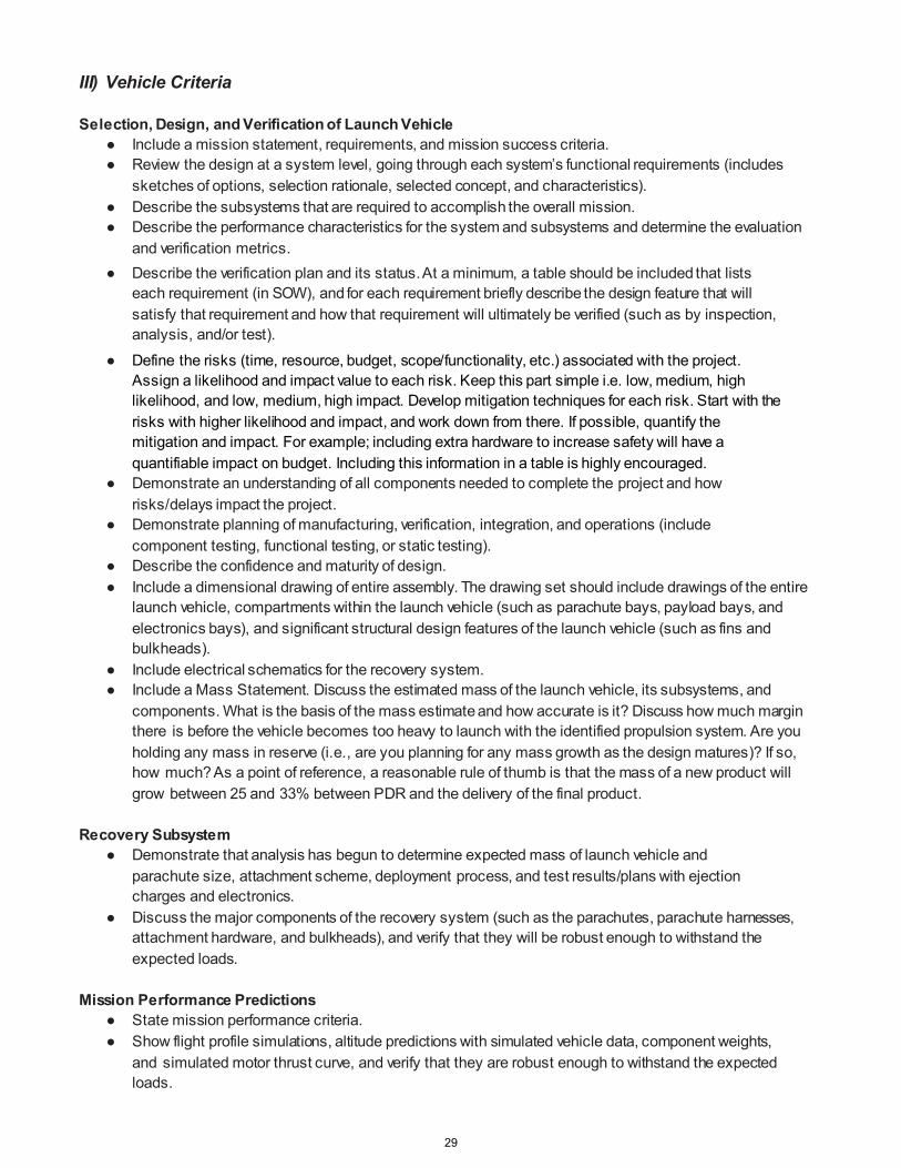
III) Vehicle Criteria Selection, Design, and Verification of Launch Vehicle
● Include a mission statement, requirements, and mission success criteria. ● Review the design at a system level, going through each system’s functional requirements (includes
sketches of options, selection rationale, selected concept, and characteristics). ● Describe the subsystems that are required to accomplish the overall mission. ● Describe the performance characteristics for the system and subsystems and determine the evaluation
and verification metrics. ● Describe the verification plan and its status. At a minimum, a table should be included that lists
each requirement (in SOW), and for each requirement briefly describe the design feature that will satisfy that requirement and how that requirement will ultimately be verified (such as by inspection, analysis, and/or test).
● Define the risks (time, resource, budget, scope/functionality, etc.) associated with the project. Assign a likelihood and impact value to each risk. Keep this part simple i.e. low, medium, high likelihood, and low, medium, high impact. Develop mitigation techniques for each risk. Start with the risks with higher likelihood and impact, and work down from there. If possible, quantify the mitigation and impact. For example; including extra hardware to increase safety will have a quantifiable impact on budget. Including this information in a table is highly encouraged.
● Demonstrate an understanding of all components needed to complete the project and how risks/delays impact the project.
● Demonstrate planning of manufacturing, verification, integration, and operations (include component testing, functional testing, or static testing).
● Describe the confidence and maturity of design. ● Include a dimensional drawing of entire assembly. The drawing set should include drawings of the entire
launch vehicle, compartments within the launch vehicle (such as parachute bays, payload bays, and electronics bays), and significant structural design features of the launch vehicle (such as fins and bulkheads).
● Include electrical schematics for the recovery system. ● Include a Mass Statement. Discuss the estimated mass of the launch vehicle, its subsystems, and
components. What is the basis of the mass estimate and how accurate is it? Discuss how much margin there is before the vehicle becomes too heavy to launch with the identified propulsion system. Are you holding any mass in reserve (i.e., are you planning for any mass growth as the design matures)? If so, how much? As a point of reference, a reasonable rule of thumb is that the mass of a new product will grow between 25 and 33% between PDR and the delivery of the final product.
Recovery Subsystem
● Demonstrate that analysis has begun to determine expected mass of launch vehicle and parachute size, attachment scheme, deployment process, and test results/plans with ejection charges and electronics.
● Discuss the major components of the recovery system (such as the parachutes, parachute harnesses, attachment hardware, and bulkheads), and verify that they will be robust enough to withstand the expected loads.
Mission Performance Predictions
● State mission performance criteria. ● Show flight profile simulations, altitude predictions with simulated vehicle data, component weights,
and simulated motor thrust curve, and verify that they are robust enough to withstand the expected loads.
29
● Show stability margin, simulated Center of Pressure (CP)/Center of Gravity (CG) relationship and locations. ● Calculate the kinetic energy at landing for each independent and tethered section of the launch vehicle. ● Calculate the drift for each independent section of the launch vehicle from the launch pad for five
different cases: no wind, 5-mph wind, 10-mph wind, 15-mph wind, and 20-mph wind. Interfaces and Integration
● Describe payload integration plan with an understanding that the payload must be co-developed with the vehicle, be compatible with stresses placed on the vehicle, and integrate easily and simply.
● Describe the interfaces that are internal to the launch vehicle, such as between compartments and subsystems of the launch vehicle.
● Describe the interfaces between the launch vehicle and the ground (mechanical, electrical, and/or wireless/transmitting).
● Describe the interfaces between the launch vehicle and the ground launch system. Safety
● Develop a preliminary checklist of final assembly and launch procedures. ● Identify a safety officer for your team. ● Provide a preliminary Hazard analysis, including hazards to personnel. Also, include the failure modes of
the proposed design of the rocket, payload integration, and launch operations. Include proposed mitigations to all hazards (and verifications if any are implemented yet). Rank the risk of each Hazard for both likelihood and severity.
• Include data indicating that the hazards have been researched (especially personnel). Examples: NAR regulations, operator’s manuals, MSDS, etc.
● Discuss any environmental concerns. • This should include how the vehicle affects the environment, and how the environment can
affect the vehicle. IV) AGSE (As Necessary)/Payload Criteria
Selection, Design, and Verification of AGSE
● Review the design at a system level, going through each system’s functional requirements (includes sketches of options, selection rationale, selected concept, and characteristics).
● Describe the AGSE/payload subsystems that are required to accomplish the mission objectives. ● Describe the performance characteristics for the system and subsystems and determine the evaluation
and verification metrics. ● Describe the verification plan and its status. At a minimum, a table should be included that lists each
AGSE or payload requirement and for each requirement briefly describe the design feature that will satisfy that requirement and how that requirement will ultimately be verified (such as by inspection, analysis, and/or test).
● Describe preliminary integration plan. ● Determine the precision of instrumentation, repeatability of measurement, and recovery system. ● Include drawings and electrical schematics for the key elements of the AGSE/payload. ● Discuss the key components of the AGSE/payload and how they will work together to achieve the
desired mission objectives AGSE/Payload Concept Features and Definition
● Creativity and originality ● Uniqueness or significance ● Suitable level of challenge
30

Science Value ● Describe AGSE objectives. ● State the AGSE success criteria. ● Describe the experimental logic, approach, and method of investigation. ● Describe test and measurement, variables, and controls. ● Show relevance of expected data and accuracy/error analysis. ● Describe the preliminary experiment process procedures.
V) Project Plan
Show status of activities and schedule
● Budget plan (in as much detail as possible) ● Funding plan ● Timeline (in as much detail as possible). GANTT charts are encouraged with a discussion of the
critical path. ● Educational engagement plan and status
VI) Conclusion
Preliminary Design Review Presentation Please include the following in your presentation:
● Vehicle dimensions, materials, and justifications ● Static stability margin ● Plan for vehicle safety verification and testing ● Baseline motor selection and justification ● Thrust-to-weight ratio and rail exit velocity ● Launch vehicle verification and test plan overview ● Drawing/Discussion of each major component and subsystem, especially the recovery subsystem ● Baseline AGSE/Payload design ● AGSE/Payload verification and test plan overview
The PDR will be presented to a panel that may be comprised of any combination of scientists, engineers, safety experts, education specialists, and industry partners. This review should be viewed as the opportunity to convince the NASA Review Panel that the preliminary design will meet all requirements, has a high probability of meeting the mission objectives, and can be safely constructed, tested, launched, and recovered. Upon successful completion of the PDR, the team is given the authority to proceed into the final design phase of the life cycle that will culminate in the Critical Design Review.
It is expected that the team participants deliver the report and answer all questions. The mentor shall not participate in the presentation.
The presentation of the PDR shall be well prepared with a professional overall appearance. This includes, but is not limited to, the following: easy-to-see slides; appropriate placement of pictures, graphs, and videos; professional appearance of the presenters; speaking clearly and loudly; looking into the camera; referring to the slides, not reading them; and communicating to the panel in an appropriate and professional manner. The slides should use dark text on a light background.
31

Critical Design Review (CDR) Vehicle and Payload Experiment Criteria
The CDR demonstrates that the maturity of the design is appropriate to support proceeding to full-scale fabrication, assembly, integration, and test that the technical effort is on track to complete the flight and ground system development and mission operations in order to meet overall performance requirements within the identified cost schedule constraints. Progress against management plans, budget, and schedule, as well as risk assessment, are presented. The CDR is a review of the final design of the launch vehicle and payload system. All analyses should be complete and some critical testing should be complete. The CDR Report and Presentation should be independent of the PDR Report and Presentation. However, the CDR Report and Presentation may have the same basic content and structure as the PDR documents, but with final design information that may or may not have changed since PDR. Although there should be discussion of subscale models, the CDR documents are to primarily discuss the final design of the full scale launch vehicle and subsystems.
The panel will be expecting a professional and polished report. It is advised to follow the order of sections as they appear below.
Critical Design Review Report All information included in the general information sections of the project proposal and PDR shall be included. I) Summary of CDR report (1 page maximum)
Team Summary
● Team name and mailing address ● Name of mentor, NAR/TRA number and certification level
Launch Vehicle Summary
● Size and mass ● Motor choice ● Recovery system ● Rail size ● Milestone Review Flysheet
AGSE (As Necessary)/Payload Summary
● AGSE/Payload title ● Summarize method for autonomous procedures ant the AGSE ● Summarize experiment
II) Changes made since PDR (1-2 pages maximum)
Highlight all changes made since PDR and the reason for those changes.
● Changes made to vehicle criteria ● Changes made to AGSE/Payload criteria ● Changes made to project plan
32

III) Vehicle Criteria Design and Verification of Launch Vehicle Flight Reliability and Confidence
● Include mission statement, requirements, and mission success criteria ● Include major milestone schedule (project initiation, design, manufacturing, verification,
operations, and major reviews) ● Review the design at a system level
○ Final drawings and specifications ○ Final analysis and model results, anchored to test data ○ Test description and results ○ Final motor selection
● Demonstrate that the design can meet all system level functional requirements. For each requirement, state the design feature that satisfies that requirement and how that requirement has been, or will be, verified.
● Specify approach to workmanship as it relates to mission success. ● Discuss planned additional component, functional, or static testing. ● Status and plans of remaining manufacturing and assembly. ● Discuss the integrity of design.
○ Suitability of shape and fin style for mission ○ Proper use of materials in fins, bulkheads, and structural elements ○ Proper assembly procedures, proper attachment and alignment of elements, solid connection
points, and load paths ○ Sufficient motor mounting and retention ○ Status of verification ○ Drawings of the launch vehicle, subsystems, and major components ○ Include a Mass Statement. Discuss the estimated mass of the final design and its subsystems
and components. Discuss the basis and accuracy of the mass estimate, the expected mass growth between CDR and the delivery of the final product, and the sensitivity of the launch vehicle to mass growth (e.g. How much mass margin there is before the vehicle becomes too heavy to launch on the selected propulsion system?).
● Discuss the safety and failure analysis. Subscale Flight Results
● Include actual flight data from onboard computers, if available. ● Compare the predicted flight model to the actual flight data. Discuss the results. ● Discuss how the subscale flight data has impacted the design of the full-scale launch vehicle.
Recovery Subsystem
● Describe the parachute, harnesses, bulkheads, and attachment hardware. ● Discuss the electrical components and how they will work together to safely recover the launch vehicle. ● Include drawings/sketches, block diagrams, and electrical schematics. ● Discuss the kinetic energy at significant phases of the mission, especially at landing. ● Discuss test results. ● Discuss safety and failure analysis.
33

Mission Performance Predictions ● State the mission performance criteria. ● Show flight profile simulations, altitude predictions with final vehicle design, weights, and actual
motor thrust curve. ● Show thoroughness and validity of analysis, drag assessment, and scale modeling results. ● Show stability margin and the actual CP and CG relationship and locations.
AGSE/Payload Integration Ease of integration
● Describe integration plan. ● Compatibility of elements. ● Simplicity of integration procedure. ● Discuss any changes in the AGSE or payload resulting from the subscale test.
Launch concerns and operation procedures
● Submit a draft of final assembly and launch procedures including: ○ Recovery preparation. ○ Motor preparation. ○ Setup on launcher. ○ Igniter installation. ○ Troubleshooting. ○ Post-flight inspection.
Safety and Environment (Vehicle and AGSE/Payload)
● Update the preliminary analysis of the failure modes of the proposed design of the rocket and payload integration and launch operations, including proposed, and completed mitigations.
● Update the listing of personnel hazards and data demonstrating that safety hazards have been researched, such as material safety data sheets, operator’s manuals, and NAR regulations, and that hazard mitigations have been addressed and enacted.
● Discuss any environmental concerns. ○ This should include how the vehicle affects the environment, and how the environment can affect
the vehicle. IV) AGSE (As Necessary)/Payload Criteria
Testing and Design of AGSE/Payload Equipment
● Review the design at a system level. ○ Drawings and specifications ○ Analysis results ○ Test results ○ Integrity of design
● Demonstrate that the design can meet all system-level functional requirements. ● Specify approach to workmanship as it relates to mission success. ● Discuss planned component testing, functional testing, or static testing. ● Status and plans of remaining manufacturing and assembly. ● Describe integration plan. ● Discuss the precision of instrumentation and repeatability of measurement.
34

● Discuss the AGSE/payload electronics with special attention given to safety switches and indicators. ○ Drawings and schematics ○ Block diagrams ○ Batteries/power ○ Switch and indicator wattage and location ○ Test plans
● Provide a safety and failure analysis. AGSE/Payload Concept Features and Definition
● Creativity and originality ● Uniqueness or significance ● Suitable level of challenge
Science Value
● Describe AGSE/payload objectives. ● State the AGSE/payload success criteria. ● Describe the experimental logic, approach, and method of investigation. ● Describe test and measurement, variables, and controls. ● Show relevance of expected data and accuracy/error analysis. ● Describe the experiment process procedures.
V) Project Plan
Show status of activities and schedule
● Budget plan (in as much detail as possible) ● Funding plan ● Timeline (in as much detail as possible). GANTT charts are encouraged with a discussion of the
critical path. ● Educational engagement plan and status
VI) Conclusion
35

Critical Design Review Presentation Please include the following information in your presentation:
● Final launch vehicle and AGSE dimensions ● Discuss key design features ● Final motor choice ● Rocket flight stability in static margin diagram ● Thrust-to-weight ratio and rail exit velocity ● Mass Statement and mass margin ● Parachute sizes, recovery harness type, size, length, and descent rates ● Kinetic energy at key phases of the mission, especially landing ● Predicted drift from the launch pad with 5-, 10-, 15-, and 20-mph wind ● Test plans and procedures ● Scale model flight test ● Tests of the staged recovery system ● Final AGSE/payload design overview ● AGSE/Payload integration ● Interfaces (internal within the launch vehicle and external to the ground) ● Status of requirements verification
The CDR will be presented to a panel that may be comprised of any combination of scientists, engineers, safety experts, education specialists, and industry partners. The team is expected to present and defend the final design of the launch vehicle (including the AGSE/payload), showing that design meets the mission objectives and requirements and that the design can be safety, constructed, tested, launched, and recovered. Upon successful completion of the CDR, the team is given the authority to proceed into the construction and verification phase of the life cycle which will culminate in a Flight Readiness Review.
It is expected that the team participants deliver the report and answer all questions. The mentor shall not participate in the presentation.
The presentation of the CDR shall be well prepared with a professional overall appearance. This includes, but is not limited to, the following: easy-to-see slides; appropriate placement of pictures, graphs, and videos; professional appearance of the presenters; speaking clearly and loudly; looking into the camera; referring to the slides, not reading them; and communicating to the panel in an appropriate and professional manner. The slides should be made with dark text on a light background.
36

Flight Readiness Review (FRR) Vehicle and Payload Experiment Criteria
The FRR examines tests, demonstrations, analyses, and audits that determine the overall system (all projects working together) readiness for a safe and successful flight/launch and for subsequent flight operations of the as-built rocket and payload system. It also ensures that all flight and ground hardware, software, personnel, and procedures are operationally ready.
The panel will be expecting a professional and polished report. It is advised to follow the order of sections as they appear below.
Flight Readiness Review Report
I) Summary of FRR report (1 page maximum)
Team Summary
● Team name and mailing address ● Name of mentor, NAR/TRA number and certification level
Launch Vehicle Summary
● Size and mass ● Final motor choice ● Recovery system ● Rail size ● Milestone Review Flysheet
AGSE (As Necessary)/Payload Summary
● AGSE/Payload title ● Summarize the AGSE ● Summarize experiment
II) Changes made since CDR (1-2 pages maximum)
Highlight all changes made since CDR and the reason for those changes.
● Changes made to vehicle criteria ● Changes made to AGSE/Payload criteria ● Changes made to project plan
III) Vehicle Criteria
Design and Construction of Vehicle
● Describe the design and construction of the launch vehicle, with special attention to the features that will enable the vehicle to be launched and recovered safely.
○ Structural elements (such as airframe, fins, bulkheads, attachment hardware, etc.). ○ Electrical elements (wiring, switches, battery retention, retention of avionics boards, etc.). ○ Drawings and schematics to describe the assembly of the vehicle.
37

● Discuss flight reliability confidence. Demonstrate that the design can meet mission success criteria. Discuss analysis, and component, functional, or static testing.
● Present test data and discuss analysis, and component, functional, or static testing of components and subsystems.
● Describe the workmanship that will enable mission success. ● Provide a safety and failure analysis, including a table with failure modes, causes, effects, and risk
mitigations. ● Discuss full-scale launch test results. Present and discuss actual flight data. Compare and contrast
flight data to the predictions from analysis and simulations. ● Provide a Mass Report and the basis for the reported masses.
Recovery Subsystem
● Describe and defend the robustness of as-built and as-tested recovery system. ○ Structural elements (such as bulkheads, harnesses, attachment hardware, etc.). ○ Electrical elements (such as altimeters/computers, switches, connectors). ○ Redundancy features. ○ Parachute sizes and descent rates ○ Drawings and schematics of the electrical and structural assemblies. ○ Rocket-locating transmitters with a discussion of frequency, wattage, and range. ○ Discuss the sensitivity of the recovery system to onboard devices that generate electromagnetic
fields (such as transmitters). This topic should also be included in the Safety and Failure Analysis section.
● Suitable parachute size for mass, attachment scheme, deployment process, test results with ejection charge and electronics
● Safety and failure analysis. Include table with failure modes, causes, effects, and risk mitigations. Mission Performance Predictions
● State mission performance criteria. ● Provide flight profile simulations, altitude predictions with real vehicle data, component weights, and
actual motor thrust curve. Include real values with optimized design for altitude. Include sensitivities. ● Thoroughness and validity of analysis, drag assessment, and scale modeling results. Compare analyses
and simulations to measured values from ground and/or flight tests. Discuss how the predictive analyses and simulation have been made more accurate by test and flight data.
● Provide stability margin, with actual CP and CG relationship and locations. Include dimensional moment diagram or derivation of values with points indicated on vehicle. Include sensitivities.
● Discuss the management of kinetic energy through the various phases of the mission, with special attention to landing.
● Discuss the altitude of the launch vehicle and the drift of each independent section of the launch vehicle for winds of 0-, 5-, 10-, 15-, and 20-mph.
Verification (Vehicle)
● For each requirement (in SOW), describe how that requirement has been satisfied and by what method the requirement was verified. Note: Requirements are often satisfied by design features of a product, and requirements are usually verified by one or more of the following methods: analysis, inspection, and test.
● The verification statement for each requirement should include results of the analysis, inspection, and/or test which prove that the requirement has been properly verified.
38
Safety and Environment (Vehicle) ● Provide a safety and mission assurance analysis. Provide a Failure Modes and Effects Analysis (which
can be as simple as a table of failure modes, causes, effects, and mitigations/controls put in place to minimize the occurrence or effect of the hazard or failure). Discuss likelihood and potential consequences for the top 5 to 10 failures (most likely to occur and/or worst consequences).
● As the program is moving into the operational phase of the Life Cycle, update the listing of personnel hazards, including data demonstrating that safety hazards that will still exist after FRR. Include a table which discusses the remaining hazards and the controls that have been put in place to minimize those safety hazards to the greatest extent possible.
● Discuss any environmental concerns that remain as the project moves into the operational phase of the life cycle.
AGSE Integration
● Describe the integration of the AGSE into the launch vehicle. ● Demonstrate compatibility of elements and show fit at interface dimensions. ● Describe and justify payload-housing integrity. ● Demonstrate integration: show a diagram of components and assembly with documented process.
IV) AGSE (As Necessary)/Payload Criteria
Experiment Concept This concerns the quality of science. Give clear, concise, and descriptive explanations.
● Creativity and originality ● Uniqueness or significance
Science Value
● Describe AGSE/payload objectives in a concise and distinct manner. ● State the mission success criteria. ● Describe the experimental logic, scientific approach, and method of investigation. ● Explain how it is a meaningful test and measurement, and explain variables and controls. ● Discuss the relevance of expected data, along with an accuracy/error analysis, including tables and plots ● Provide detailed experiment process procedures.
AGSE/Payload Design
● Describe the design and construction of the AGSE/payload and demonstrate that the design meets all mission requirements.
○ Structural elements (such as airframe, bulkheads, attachment hardware, etc.). ○ Electrical elements (wiring, switches, battery retention, retention of avionics boards, etc.). ○ Drawings and schematics to describe the design and assembly of the AGSE/payload.
● Provide information regarding the precision of instrumentation and repeatability of measurement (include calibration with uncertainty).
● Provide flight performance predictions (flight values integrated with detailed experiment operations).
● Specify approach to workmanship as it relates to mission success. ● Discuss the test and verification program.
39

Verification ● For each AGSE/payload requirement, describe how that requirement has been satisfied, and by what
method the requirement was verified. Note: Requirements are often satisfied by design features, and requirements are usually verified by one or more of the following methods: analysis, inspection, and test.
● The verification statement for each AGSE/payload requirement should include results of the analysis, inspection, and/or test which prove that the requirement has been properly verified.
Safety and Environment (AGSE/payload) This will describe all concerns, research, and solutions to safety issues related to the AGSE/payload.
● Provide a safety and mission assurance analysis. Provide a Failure Modes and Effects Analysis (which can be as simple as a table of failure modes, causes, effects, and mitigations/controls put in place to minimize the occurrence or effect of the hazard or failure). Discuss likelihood and potential consequences for the top 5 to 10 failures (most likely to occur and/or worst consequences).
● As the program is moving into the operational phase of the Life Cycle, update the listing of personnel hazards, including data demonstrating that safety hazards that will still exist after FRR. Include a table which discusses the remaining hazards and the controls that have been put in place to minimize those safety hazards to the greatest extent possible.
● Discuss any environmental concerns that still exist. V) Launch Operations Procedures
Checklist Provide detailed procedure and check lists for the following (as a minimum).
● Recovery preparation ● Motor preparation ● Setup on launcher ● Igniter installation ● Launch procedure ● Troubleshooting ● Post-flight inspection
Safety and Quality Assurance Provide detailed safety procedures for each of the categories in the Launch Operations Procedures checklist. Include the following:
● Provide data demonstrating that risks are at acceptable levels. ● Provide risk assessment for the launch operations, including proposed and completed mitigations. ● Discuss environmental concerns. ● Identify the individual that is responsible for maintaining safety, quality and procedures checklists.
VI) Project Plan
Show status of activities and schedule
● Budget plan (in as much detail as possible) ● Funding plan ● Timeline (in as much detail as possible). GANTT charts are encouraged with a discussion of the
critical path. ● Educational Engagement plan and status
VII) Conclusion
40

Flight Readiness Review Presentation Please include the following information in your presentation:
● Launch Vehicle and AGSE design and dimensions ● Discuss key design features of the launch vehicle ● Motor description ● Rocket flight stability in static margin diagram ● Launch thrust-to-weight ratio and rail exit velocity ● Mass statement ● Parachute sizes and descent rates ● Kinetic energy at key phases of the mission, especially at landing ● Predicted altitude of the launch vehicle with a 5-, 10-, 15-, and 20-mph wind ● Predicted drift from the launch pad with a 5-, 10-, 15-, and 20-mph wind ● Test plans and procedures ● Full-scale flight test. Present and discuss the actual flight test data. ● Recovery system tests ● Summary of Requirements Verification (launch vehicle) ● AGSE/payload design and dimensions ● Key design features of the launch vehicle ● AGSE/Payload integration ● Interfaces with ground systems ● Summary of requirements verification (AGSE/payload)
The FRR will be presented to a panel that may be comprised of any combination of scientists, engineers, safety experts, education specialists, and industry partners. The team is expected to present and defend the as-built launch vehicle (including the payload), showing that the launch vehicle meets all requirements and mission objectives and that the design can be safely launched and recovered. Upon successful completion of the FRR, the team is given the authority to proceed into the Launch and Operational phases of the life cycle.
It is expected that the team participants deliver the report and answer all questions. The mentor shall not participate in the presentation.
The presentation of the FRR shall be well prepared with a professional overall appearance. This includes, but is not limited to, the following: easy to see slides; appropriate placement of pictures, graphs, and videos; professional appearance of the presenters; speaking clearly and loudly; looking into the camera; referring to the slides, not reading them; and communicating to the panel in an appropriate and professional manner. The slides should be made with dark text on a light background.
41

Launch Readiness Review (LRR) Vehicle and Payload Experiment Criteria
The Launch Readiness Review (LRR) will be held by NASA and the National Association of Rocketry (NAR), our launch services provider. These inspections are only open to team members and mentors. These names were submitted as part of your team list. All rockets/AGSE will undergo a detailed, deconstructive, hands-on inspection. Your team should bring all components of the rocket and AGSE/payload except for the motor, black powder, and e-matches. Be able to present: anchored flight predictions, anchored drift predictions (15 mph crosswind), procedures and checklists, and CP and CG with loaded motor marked on the airframe. The rockets will be assessed for structural, electrical integrity, and safety features. At a minimum, all teams should have:
● An airframe prepared for flight with the exception of energetic materials. ● Data from the previous flight. ● A list of any flight anomalies that occurred on the previous full scale flight and the mitigation actions. ● A list of any changes to the airframe since the last flight. ● Flight simulations. ● Pre-flight check list and Fly Sheet.
Any team participating in the Mini/Maxi MAV portion of the completion must also participate in an AGSE inspection consisting of the following demonstrations.
• Demonstrate proper capture and containment of the payload. • Demonstrate that the launch pad can autonomously erect itself with the model/inert motor installed. • Demonstrate that the AGSE can properly install the igniter into the model/inert motor. • For each of the above stages, the team must demonstrate that all safety switches and indicators function
properly and at the correct times. Each team will demonstrate these tasks with the RSO present who will have final word on whether the AGSE may be used on Launch Day. A “punch list” will be generated for each team. Items identified on the punch list should be corrected and verified by launch services/NASA prior to launch day. A flight card will be provided to teams, to be completed and provided at the RSO booth on launch day.
Post-Launch Assessment Review (PLAR) Vehicle and Payload Experiment Criteria
The PLAR is an assessment of system in-flight performance. The PLAR should include the following items at a minimum and be about 4-15 pages in length.
● Team name ● Motor used ● Brief payload description ● Vehicle Dimensions ● Altitude reached (Feet) ● Vehicle Summary ● Data analysis & results of vehicle ● Payload summary ● Data analysis & results of AGSE/payload ● Scientific value ● Visual data observed ● Lessons learned ● Summary of overall experience (what you attempted to do versus the results and how you felt your results
were; how valuable you felt the experience was) ● Educational Engagement summary ● Budget Summary
42

Educational Engagement Form Please complete and submit this form each time you host an educational engagement event. (Return within 2 weeks of the event end date)
School/Organization name:
Date(s) of event:
Location of event:
Instructions for participant count
Education/Direct Interactions: A count of participants in instructional, hands-on activities where participants engage in learning a STEM topic by actively participating in an activity. This includes instructor- led facilitation around an activity regardless of media (e.g. DLN, face-to-face, downlink.etc.). Example: Students learn about Newton’s Laws through building and flying a rocket. This type of interaction will count towards your requirement for the project.
Education/Indirect Interactions: A count of participants engaged in learning a STEM topic through instructor-led facilitation or presentation. Example: Students learn about Newton’s Laws through a PowerPoint presentation.
Outreach/Direct Interaction: A count of participants who do not necessarily learn a STEM topic, but are able to get a hands-on look at STEM hardware. For example, team does a presentation to students about their Student Launch project, brings their rocket and components to the event, and flies a rocket at the end of the presentation.
Outreach/Indirect Interaction: A count of participants that interact with the team. For example: The team sets up a display at the local museum during Science Night. Students come by and talk to the team about their project.
Grade level and number of participants: (If you are able to break down the participants into grade levels: PreK-4, 5-9, 10-12,and 12+, this will be helpful.)
Participant’s Grade Level
Education Outreach
Direct Interactions Indirect Interactions Direct Interactions
Indirect Interactions
K-4 5-9 10-12 12+ Educators (5-9) Educators (other)
Are the participants with a special group/organization (i.e. Girl Scouts, 4-H, school)? Y N
If yes, what group/organization?
Briefly describe your activities with this group:
43

Did you conduct an evaluation? If so, what were the results? Describe the comprehensive feedback received.
44
Safety

High Power Rocket Safety Code Provided by the National Association of Rocketry
1. Certification. I will only fly high power rockets or possess high power rocket motors that are within the scope of my user certification and required licensing.
2. Materials. I will use only lightweight materials such as paper, wood, rubber, plastic, fiberglass, or when
necessary ductile metal, for the construction of my rocket.
3. Motors. I will use only certified, commercially made rocket motors, and will not tamper with these motors or use them for any purposes except those recommended by the manufacturer. I will not allow smoking, open flames, nor heat sources within 25 feet of these motors.
4. Ignition System. I will launch my rockets with an electrical launch system, and with electrical motor
igniters that are installed in the motor only after my rocket is at the launch pad or in a designated prepping area. My launch system will have a safety interlock that is in series with the launch switch that is not installed until my rocket is ready for launch, and will use a launch switch that returns to the “off” position when released. The function of onboard energetics and firing circuits will be inhibited except when my rocket is in the launching position.
5. Misfires. If my rocket does not launch when I press the button of my electrical launch system, I will
remove the launcher’s safety interlock or disconnect its battery, and will wait 60 seconds after the last launch attempt before allowing anyone to approach the rocket.
6. Launch Safety. I will use a 5-second countdown before launch. I will ensure that a means is available to
warn participants and spectators in the event of a problem. I will ensure that no person is closer to the launch pad than allowed by the accompanying Minimum Distance Table. When arming onboard energetics and firing circuits I will ensure that no person is at the pad except safety personnel and those required for arming and disarming operations. I will check the stability of my rocket before flight and will not fly it if it cannot be determined to be stable. When conducting a simultaneous launch of more than one high power rocket I will observe the additional requirements of NFPA 1127.
7. Launcher. I will launch my rocket from a stable device that provides rigid guidance until the rocket has
attained a speed that ensures a stable flight, and that is pointed to within 20 degrees of vertical. If the wind speed exceeds 5 miles per hour I will use a launcher length that permits the rocket to attain a safe velocity before separation from the launcher. I will use a blast deflector to prevent the motor’s exhaust from hitting the ground. I will ensure that dry grass is cleared around each launch pad in accordance with the accompanying Minimum Distance table, and will increase this distance by a factor of 1.5 and clear that area of all combustible material if the rocket motor being launched uses titanium sponge in the propellant.
8. Size. My rocket will not contain any combination of motors that total more than 40,960 N-sec (9208
pound-seconds) of total impulse. My rocket will not weigh more at liftoff than one-third of the certified average thrust of the high power rocket motor(s) intended to be ignited at launch.
9. Flight Safety. I will not launch my rocket at targets, into clouds, near airplanes, nor on trajectories that
take it directly over the heads of spectators or beyond the boundaries of the launch site, and will not put any flammable or explosive payload in my rocket. I will not launch my rockets if wind speeds exceed 20 miles per hour. I will comply with Federal Aviation Administration airspace regulations when flying, and will ensure that my rocket will not exceed any applicable altitude limit in effect at that launch site.
10. Launch Site. I will launch my rocket outdoors, in an open area where trees, power lines, occupied
buildings, and persons not involved in the launch do not present a hazard, and that is at least as large on its smallest dimension as one-half of the maximum altitude to which rockets are allowed to be flown at that site or 1500 feet, whichever is greater, or 1000 feet for rockets with a combined total impulse of less than 160 N-sec, a total liftoff weight of less than 1500 grams, and a maximum expected altitude of less than 610 meters (2000 feet).
46

11. Launcher Location. My launcher will be 1500 feet from any occupied building or from any public highway on which traffic flow exceeds 10 vehicles per hour, not including traffic flow related to the launch. It will also be no closer than the appropriate Minimum Personnel Distance from the accompanying table from any boundary of the launch site.
12. Recovery System. I will use a recovery system such as a parachute in my rocket so that all parts of my
rocket return safely and undamaged and can be flown again, and I will use only flame-resistant or fireproof recovery system wadding in my rocket.
13. Recovery Safety. I will not attempt to recover my rocket from power lines, tall trees, or other dangerous
places, fly it under conditions where it is likely to recover in spectator areas or outside the launch site, nor attempt to catch it as it approaches the ground.
47

Minimum Distance Table
Installed Total Impulse (Newton-
Seconds)
Equivalent High Power Motor
Type
Minimum Diameter of
Cleared Area (ft.) Minimum Personnel
Distance (ft.) Minimum Personnel Distance
(Complex Rocket) (ft.)
0 – 320.00
H or smaller
50
100
200
320.01 – 640.00
I
50
100
200
640.01 – 1,280.00
J
50
100
200
1,280.01 – 2,560.00
K
75
200
300
2,560.01 – 5,120.00
L
100
300
500
5,120.01 – 10,240.00
M
125
500
1000
10,240.01 – 20,480.00
N
125
1000
1500
20,480.01 – 40,960.00
O
125
1500
2000
Note: A Complex rocket is one that is multi-staged or that is propelled by two or more rocket motors
Revision of July 2008 Provided by the National Association of Rocketry (www.nar.org)
48

Related Documents

Nat
iona
l Aer
onau
tics
and
Spac
e Ad
min
istra
tion
Cha
rles
Pie
rce
Chi
ef, S
pace
craf
t Pro
puls
ion
Sys
tem
s B
ranc
h,
NA
SA
- Mar
shal
l Spa
ce F
light
Cen
ter
ww
w.n
asa.
gov
50

P
urpo
se /
Obj
ectiv
e
NA
SA
Pro
ject
Life
Cyc
le (T
ypic
al)
P
relim
inar
y D
esig
n R
evie
w
C
ritic
al (F
inal
) Des
ign
Rev
iew
Flig
ht R
eadi
ness
Rev
iew
Pos
t Flig
ht
NA
SA
Pro
ject
Life
Cyc
le, J
uly
2012
51
P
lan
for t
he d
esig
n, b
uild
, ver
ifica
tion,
flig
ht o
pera
tions
, and
di
spos
al o
f the
des
ired
syst
em
M
aint
ain
cons
iste
ncy
betw
een
proj
ects
Set
exp
ecta
tions
for P
roje
ct M
anag
ers,
Sci
entis
ts, &
Eng
inee
rs
◦Pl
ans
and
Del
iver
able
s◦
Fide
lity
◦Ti
min
g
NA
SA
Pro
ject
Life
Cyc
le, J
uly
2012
52

Ref
eren
ce:
NP
R 7
120.
5D, F
igur
e 2-
4: “
The
NA
SA P
roje
ct L
ife C
ycle
” N
AS
A P
roje
ct L
ife C
ycle
, Jul
y 20
12
53

Phas
e A
Acqu
isiti
on &
Re
quire
men
ts
Phas
e B
Prel
imin
ary
Des
ign
Phas
e C
Fina
l Des
ign
Phas
e D
Fa
bric
atio
n &
Laun
ch
Phas
e E
Ope
ratio
ns &
Su
stai
nmen
t
Phas
e F
Dis
posa
l
Auth
ority
to P
roce
ed
SRR
PDR
CDR
FRR La
unch
PL
AR
•AT
P (A
utho
rity
to P
roce
ed) –
Fun
ding
is a
pplie
d to
the
cont
ract
/effo
rt an
d w
ork
perfo
rman
ce c
an b
egin
•S
RR
(Sys
tem
Req
uire
men
ts R
evie
w) –
Top
Lev
el R
equi
rem
ents
are
con
verte
d in
to s
yste
m re
quire
men
ts.
Sys
tem
Req
uire
men
ts a
re re
view
ed a
nd a
utho
rity
is g
iven
to p
roce
ed in
to P
relim
inar
y D
esig
n. T
he N
AS
AS
tude
nt L
aunc
h sk
ips
this
ste
p. N
ote:
Thi
s re
view
is s
kipp
ed, d
ue to
tim
e co
nstra
ints
.•
PD
R (P
relim
inar
y D
esig
n R
evie
w) –
Pre
limin
ary
Des
ign
is re
view
ed a
nd a
utho
rity
is g
iven
to p
roce
ed in
to F
inal
Des
ign.
•C
DR
(Crit
ical
Des
ign
Rev
iew
) – F
inal
Des
ign
is re
v iew
ed a
nd a
utho
rity
is g
iven
to p
roce
ed to
bui
ld th
e sy
stem
.•
FRR
(Flig
ht R
eadi
ness
Rev
iew
) – A
s-bu
ilt d
esig
n an
d te
st d
ata
are
revi
ewed
and
aut
horit
y is
giv
en fo
r Lau
nch.
•P
LAR
(Pos
t Lau
nch
Ass
essm
ent R
epor
t) -
Sum
mar
ize
proj
ect (
crad
le to
gra
ve),
disc
uss
mis
sion
resu
lts a
ndco
mpa
re to
exp
ecte
d re
sults
, doc
umen
t les
sons
lear
ned.
NAS
A Pr
ojec
t Life
Cyc
le, J
uly
2012
54

O
bjec
tive
◦Pr
ove
the
feas
ibilit
y to
bui
ld a
nd la
unch
the
rock
et/p
aylo
ad d
esig
n.◦
Prov
e th
at a
ll sy
stem
requ
irem
ents
will
be m
et.
◦R
ecei
ve a
utho
rity
to p
roce
ed to
the
Fina
l Des
ign
Phas
e
Typi
cal P
rodu
cts
(Veh
icle
and
Pay
load
) ◦
Prel
imin
ary
Des
ign
Dis
cuss
ion
D
raw
ings
, ske
tche
s
Iden
tific
atio
n an
d di
scus
sion
of c
ompo
nent
s
Anal
yses
(suc
h as
Veh
icle
Tra
ject
ory
Pred
ictio
ns) a
nd S
imul
atio
n R
esul
ts
R
isks
Mas
s St
atem
ent a
nd M
ass
Mar
gin
◦Sc
hedu
le fr
om P
DR
to L
aunc
h (in
clud
ing
desi
gn, b
uild
, tes
t)◦
Cos
t/Bud
get S
tate
men
t◦
Mis
sion
Pro
file
(Con
cept
of O
pera
tions
)◦
Inte
rface
s (w
ithin
the
syst
em a
nd e
xter
nal t
o th
e sy
stem
)◦
Test
and
Ver
ifica
tion
Plan
(for
sat
isfy
ing
requ
irem
ents
)◦
Gro
und
Supp
ort E
quip
men
t Des
igns
/Iden
tific
atio
n◦
Safe
ty F
eatu
res
NA
SA
Pro
ject
Life
Cyc
le, J
uly
2012
55

O
bjec
tive
◦C
ompl
ete
the
final
des
ign
of th
e ro
cket
/pay
load
sys
tem
◦R
ecei
ve a
utho
rity
to p
roce
ed in
to F
abric
atio
n an
d Ve
rific
atio
n ph
ase
In
a p
erfe
ct w
orld
, fab
ricat
ion/
proc
urem
ent
of th
e fin
al s
yste
m w
ould
n’t b
egin
unt
il a
succ
essf
ul c
ompl
etio
n of
CD
R.
D
ue to
sch
edul
e co
nstra
ints
, how
ever
, it i
s of
ten
nece
ssar
y to
sta
rt pr
ocur
emen
ts a
nd
fabr
icat
ion
prio
r to
CD
R.
Pr
ocur
emen
ts a
nd F
abric
atio
n th
at s
tart
prio
r to
CD
R a
dd a
n ex
tra r
isk
to th
e Pr
ojec
t be
caus
e de
sign
issu
es m
ay b
e di
scov
ered
at C
DR
that
impa
ct p
rocu
rem
ents
or
fabr
icat
ion.
Ty
pica
l Pro
duct
s (V
ehic
le a
nd P
aylo
ad)
◦PD
R D
eliv
erab
les
(mat
ured
to re
flect
the
final
des
ign)
◦R
epor
t and
dis
cuss
com
plet
ed te
sts
◦Pr
oced
ures
and
Che
cklis
ts
NA
SA
Pro
ject
Life
Cyc
le, J
uly
2012
56

O
bjec
tive
◦Pr
ove
that
the
Roc
ket/P
aylo
ad S
yste
m h
as b
een
fully
bui
lt, te
sted
, and
ver
ified
tom
eet t
he s
yste
m re
quire
men
ts◦
Prov
e th
at a
ll sy
stem
requ
irem
ents
hav
e be
en, o
r will
be,
met
◦R
ecei
ve a
utho
rity
to p
roce
ed to
Lau
nch
Ty
pica
l Pro
duct
s (V
ehic
le a
nd P
aylo
ad)
◦Sc
hedu
le◦
Cos
t Sta
tem
ent
◦D
esig
n O
verv
iew
Ke
y co
mpo
nent
s
Key
draw
ings
and
layo
uts
Tr
ajec
tory
and
oth
er k
ey a
naly
ses
Ke
y Sa
fety
Fea
ture
s
Mas
s St
atem
ent
R
emai
ning
Ris
ks
◦M
issi
on P
rofil
e◦
Pres
enta
tion
and
anal
ysis
and
mod
els
(use
real
test
dat
a)◦
Syst
em R
equi
rem
ents
Ver
ifica
tion
◦G
roun
d Su
ppor
t Equ
ipm
ent
◦Pr
oced
ures
and
Che
ck L
ists
NA
SA
Pro
ject
Life
Cyc
le, J
uly
2012
57

O
bjec
tive
◦To
per
form
a h
ands
-on
final
insp
ectio
n of
the
rock
et s
yste
m, p
rior t
o la
unch
◦P
erfo
rmed
by
the
oper
ator
s of
the
Laun
ch R
ange
Pr
oces
s ◦
Roc
kets
dec
onst
ruct
ed
Mec
hani
cal c
ompo
nent
s pu
lled
and
twis
ted
E
lect
roni
cs a
nd W
iring
insp
ecte
d (a
s m
uch
as p
ossi
ble)
Rec
over
y S
yste
m f
ully
insp
ecte
d ◦
Que
stio
ns a
sked
A
rmin
g, A
ctiv
atio
n, E
xecu
tion
Seq
uenc
es
R
ocke
t an
d P
aylo
ad F
unct
ions
◦
Laun
ch D
ay P
roce
dure
s re
view
ed◦
Que
stio
ns A
nsw
ered
(any
thin
g ab
out L
aunc
h D
ay o
r Ran
ge O
pera
tions
)◦
Act
ions
giv
en to
repa
ir un
safe
ele
men
ts in
the
rock
et s
yste
m (i
f any
are
foun
d)
N
ote:
Thi
s in
spec
tion
is a
Pre
Ran
ge S
afet
y O
ffice
r (R
SO) i
nspe
ctio
n.
◦It
occu
rs o
ne d
ay b
efor
e la
unch
and
it p
urpo
se is
to g
ive
the
Stu
dent
Tea
ms
an o
ppor
tuni
ty to
cor
rect
hard
war
e is
sues
that
cou
ld o
ther
wis
e re
sult
in th
e de
nial
of l
aunc
h of
thei
r roc
ket.
◦A
final
RS
O in
spec
tion
will
occ
ur a
t the
laun
ch s
ite (j
ust l
ike
a no
rmal
NA
R/T
RA
RS
O In
spec
tion
at th
ela
unch
site
).
NA
SA
Pro
ject
Life
Cyc
le, J
uly
2012
58

S
umm
ary
of th
e P
roje
ct
S
umm
ary
of th
e Ve
hicl
e an
d P
aylo
ad
◦Es
peci
ally
not
e an
ythi
ng th
at c
hang
ed a
fter F
RR
P
rese
ntat
ion
of V
ehic
le a
nd P
aylo
ad R
esul
ts
◦C
ompa
rison
to p
redi
cted
resu
lts◦
Dis
cuss
ion
of a
nom
alie
s
Less
ons
Lear
ned
NA
SA
Pro
ject
Life
Cyc
le, J
uly
2012
59

ww
w.n
asa.
gov
60

Nat
iona
l Aer
onau
tics
and
Spac
e A
dmin
istra
tion Ha
zard
Ana
lysi
s
Intr
oduc
tion
to M
anag
ing
Risk
ww
w.n
asa.
gov
61

Wha
t is a
Haz
ard?
Put s
impl
y, it’
s an
outc
ome
that
will
hav
e an
ad
vers
e af
fect
on
you,
you
r pro
ject
, or t
he
envi
ronm
ent.
A cl
assic
exa
mpl
e of
a H
azar
d is
a Fi
re o
r Exp
losio
n.–
A ha
zard
has
man
y pa
rts,
all
of w
hich
pla
y in
to
how
we
cate
goriz
e it,
and
how
we
resp
ond.
–N
ot a
ll ha
zard
s are
life
thre
aten
ing
or h
ave
cata
stro
phic
out
com
es. T
hey
can
be m
ore
beni
gn,
like
cuts
and
bru
ises,
fund
ing
issue
s, o
r sch
edul
e se
tbac
ks.
62

Haza
rd D
escr
iptio
n
A ha
zard
des
crip
tion
is co
mpo
sed
of 3
par
ts.
1.Ha
zard
–So
met
imes
cal
led
the
Haza
rdou
s ev
ent,
or in
itiat
ing
even
t2.
Caus
e –
How
the
Haza
rd o
ccur
s. S
omet
imes
ca
lled
t he
mec
hani
sm3.
Effe
ct –
The
outc
ome.
Thi
s is w
hat y
ou a
re
wor
ried
abou
t hap
peni
ng if
the
Haza
rd
man
ifest
s.
63
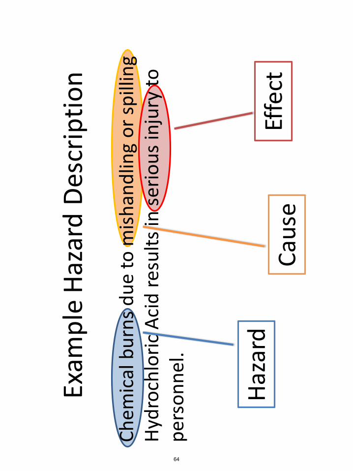
Exam
ple
Haza
rd D
escr
iptio
n
Chem
ical
bur
ns d
ue to
mish
andl
ing
or sp
illin
g Hy
droc
hlor
ic A
cid
resu
lts in
serio
us in
jury
to
pers
onne
l.
Haza
rdCa
use
Effe
ct
64

Risk
Risk
is a
mea
sure
of h
ow m
uch
emph
asis
a ha
zard
war
rant
s.Ri
sk is
def
ined
by
2 fa
ctor
s:•
Like
lihoo
d –
The
chan
ce th
at th
e ha
zard
will
oc
cur.
This
is us
ually
mea
sure
d qu
alita
tivel
y bu
t can
be
quan
tifie
d if
data
exi
sts.
•Se
verit
y –
If th
e ha
zard
occ
urs,
how
bad
will
it
be?
65

Risk
Mat
rix E
xam
ple
(exc
erpt
from
NAS
A M
PR 8
715.
15)
TAB
LE
CH
1.1
RA
C
Prob
abili
ty
Seve
rity
1C
atas
trop
hic
2C
ritic
al3
Mar
gina
l4
Neg
ligib
le
A –
Freq
uent
1A2A
3A4A
B –
Prob
able
1B2B
3B4B
C –
Occ
asio
nal
1C2C
3C4C
D –
Rem
ote
1D2D
3D4D
E -
Impr
obab
le1E
2E3E
4E
Tabl
e C
H1.
2
RIS
K A
CC
EPTA
NC
E A
ND
MA
NA
GEM
ENT
APP
RO
VA
L LE
VEL
Seve
rity
-Pro
babi
lity
Acc
epta
nce
Leve
l/App
rovi
ng A
utho
rity
Hig
h R
iskU
nacc
epta
ble.
Doc
umen
ted
appr
oval
fro
m th
e M
SFC
EM
C o
r an
equ
ival
ent
leve
l in
depe
nden
t m
anag
emen
t co
mm
ittee
.
Med
ium
Risk
Und
esira
ble.
D
ocum
ente
d ap
prov
al f
rom
the
faci
lity/
oper
atio
n ow
ner’
s D
epar
tmen
t/Lab
orat
ory/
Off
ice
Man
ager
or d
esig
nee(
s) o
r an
equi
vale
nt l
evel
m
anag
emen
t co
mm
ittee
.
Low
Risk
Acc
epta
ble.
Doc
umen
ted
appr
oval
fro
m th
e su
perv
isor
dire
ctly
res
pons
ible
for
op
erat
ing
the
faci
lity
or p
erfo
rmin
g th
e op
erat
ion.
Min
imal
Risk
Acc
epta
ble.
Doc
umen
ted
appr
oval
not
req
uire
d, b
ut a
n in
form
al r
evie
w b
y th
e su
perv
isor
dire
ctly
res
pons
ible
for
ope
ratio
n th
e fa
cilit
y or
per
form
ing
the
oper
atio
n is
high
ly r
ecom
men
ded.
U
se o
f a g
ener
ic J
HA
pos
ted
on th
e SH
E W
eb p
age
is re
com
men
ded,
if
a ge
neric
JH
A h
as b
een
deve
lope
d.
66

Risk
Con
tinue
d
Defin
ing
the
risk
on a
mat
rix h
elps
man
age
wha
t ha
zard
s ne
ed a
dditi
onal
wor
k, a
nd w
hich
are
at
an a
ccep
tabl
e le
vel.
Risk
shou
ld b
e as
sess
ed b
efor
e an
y co
ntro
ls or
m
itiga
ting
fact
ors a
re c
onsid
ered
AN
D af
ter.
Upd
ate
risk
as y
ou im
plem
ent y
our s
afet
y co
ntro
ls.
67

Miti
gatio
ns/C
ontr
ols
Iden
tifyi
ng ri
sk is
n’t u
sefu
l if y
ou d
on’t
do th
ings
to
fix
it!Co
ntro
ls/m
itiga
tions
are
the
safe
ty p
lans
and
m
odifi
catio
ns y
ou m
ake
to re
duce
you
r risk
.Ty
pes o
f Con
trol
s:•
Desig
n/An
alys
is/Te
st•
Proc
edur
es/S
afet
y Pl
ans
•PP
E (P
erso
nal P
rote
ctiv
e Eq
uipm
ent)
68

Verif
icat
ion
As y
ou p
rogr
ess t
hrou
gh th
e de
sign
revi
ew p
roce
ss,
you
will
iden
tify m
any
way
s to
cont
rol y
our h
azar
ds.
Even
tual
ly yo
u w
ill b
e re
quire
d to
“pro
ve” t
hat t
he
cont
rols
you
iden
tify a
re va
lid. T
his c
an b
e an
alys
is or
calc
ulat
ions
requ
ired
to sh
ow yo
u ha
ve st
ruct
ural
in
tegr
ity, p
roce
dure
s to
laun
ch yo
ur ro
cket
, or t
ests
to
valid
ate
your
mod
els.
Verif
icat
ions
shou
ld b
e in
clud
ed in
your
repo
rts a
s th
ey b
ecom
e av
aila
ble.
By
FRR
all v
erifi
catio
ns sh
all
be id
entif
ied.
69

Exam
ple
Haza
rd A
naly
sis
In a
dditi
on to
this
hand
book
, you
will
rece
ive
an
exam
ple
Haza
rd A
naly
sis. T
he e
xam
ple
uses
a
mat
rix fo
rmat
for d
ispla
ying
the
Haza
rds
anal
yzed
. Thi
s is n
ot re
quire
d, b
ut it
typi
cally
m
akes
org
anizi
ng a
nd u
pdat
ing
your
ana
lysis
ea
sier.
70

Safety Assessment Report (Hazard Analysis)
Hazard Analysis for the 12 ft Chamber IR Lamp Array - Foam Panel Ablation Testing
Prepared by: Industrial Safety
Bastion Technologies, Inc. for:
Safety & Mission Assurance Directorate QD12 – Industrial Safety Branch
George C. Marshall Space Flight Center
71

RAC CLASSIFICATIONS
The following tables and charts explain the Risk Assessment Codes (RACs) used to evaluate the hazards indentified in this report. RACs are established for both the initial hazard, that is; before controls have been applied, and the residual/remaining risk that remains after the implementation of controls. Additionally, table 2 provides approval/acceptance levels for differing levels of remaining risk. In all cases individual workers should be advised of the risk for each undertaking.
72

TABLE 3 Severity Definitions - A condition that can cause:Description Personnel Facility/Equipment Environmental
Safety and Health
1-Catastrophic Loss of life or a Loss of facility, systems or Irreversible severe permanent-disabling injury
associated hardware. environmental damageviolates law and regula
that tion.
2-Critical Severe injury or Major damage to facilities, Reversible environmental occupational- systems, or equipment. damage causing a violoation of related illness. law or regulation.
3-Marginal Minor injury or Minor damage to facilities, Mitigatible environmental occupational- systems, or equipment. damage without violation of law related illness. or regulation where restoration
activities can be accomplished.4-Negligible First aid injury or Minimal damage to facility, Minimal environmental damage
occupational- systems, or equipment not violating law or regulation.related illness
TABLE 4 Probability DefinitionsDescription Qualitative Definition Quantitative Defintion
A-Frequen High likelihood to occur immediately or Probability is > 0.1expected to be continuously experienced.
B-Probable Likely to occur or expected to occur frequently 0.1 probability > 0.01within time.
C-Occasional Expected to occure several times or occasionally 0.01 probability > 0.001within time.
D-Remote Unlikely to occur, but can be reasonably 0.001 ≥ probability > 0.000001expected to occure at some point within time.
E-Improbable Very unlikely to occur and an occurrence is not 0.000001 probabilityexpected to be experienced withim time.
73

Haz
ard
Cau
se
Effe
ct
Pre-
RA
C
Miti
gatio
n V
erifi
catio
n Po
st-
RA
C
Pers
onne
l ex
posu
re to
hi
gh v
olta
ge
Cont
act w
ith
ener
gize
d la
mp
bank
circ
uits
Dea
th o
r sev
ere
pers
onne
l inju
ry
1C
1.
Dur
ing
test
ope
ratio
n, la
mp
bank
s ci
rcui
ts w
ill b
e ene
rgize
d on
ly w
hen
no
pers
onne
l are
insi
de ch
ambe
r. 2.
D
oor t
o ch
ambe
r will
be c
lose
d pr
ior t
o en
ergi
zing
circ
uits
3.
TS
300
acce
ss c
ontro
ls ar
e in
plac
e for
the t
est
1.
304-
TCP-
016,
Sec
tion
3.1.
3 re
quire
s di
sabl
ing
heat
er el
ectri
cal c
ircui
t bef
ore
ente
ring
cham
ber
2.
Per 3
04-T
CP-0
16, t
ests
will
onl
y be
pe
rform
ed u
nder
per
sona
l dire
ctio
n of
Tes
t En
gine
er
3.
Acc
ess c
ontro
ls fo
r thi
s tes
t are
in
clud
ed in
304-
TCP-
016.
The
se in
clud
e:
o
Low
er E
ast T
est A
rea G
ate #
6 and
Tur
n C6
Lig
ht to
RED
o
Lo
wer
Eas
t Tes
t Are
a Gat
e #7 a
nd T
urn
C7 L
ight
to R
ED
o
Low
er E
ast T
est A
rea G
ate #
8 and
Tur
n C8
Lig
ht to
RED
o
Ve
rify
all G
over
nmen
t spo
nsor
ed v
ehicl
es
are c
lear
of t
he ar
ea.
o
Verif
y al
l non
-Gov
ernm
ent s
pons
ored
ve
hicl
es ar
e cle
ar o
f the
area
. o
M
ake t
he fo
llow
ing
anno
unce
men
t:
“Atte
ntio
n all p
erso
nnel
, tes
t ope
ratio
ns
are a
bout
to b
egin
at T
S300
. Th
e are
a is
clea
red
for t
he D
esig
nate
d Cr
ew O
nly
and
will
rem
ain
until
furth
er n
otic
e.”
(REP
EAT)
1E
Pers
onne
l ex
posu
re to
an
oxyg
en
defic
ient
en
viro
nmen
t
Entry
into
12 ft
ch
ambe
r with
un
know
n at
mos
pher
e
Dea
th o
r sev
ere
pers
onne
l inju
ry
1C
1.
Oxy
gen
mon
itors
are s
tatio
ned
insi
de ch
ambe
r and
cham
ber e
ntry
way
2.
Ch
ambe
r air
vent
ilato
r ope
rate
d af
ter e
ach
pane
l tes
t to
vent
cham
ber
3.
Atte
ndan
t will
be p
oste
d ou
tsid
e
1.
304-
TCP-
016
requ
ires i
nsta
llatio
n of
the T
est A
rticl
e usin
g “Te
st Pa
nel
Inst
all/R
emov
al Pr
oced
ure.
” Th
is p
roce
dure
re
quire
s use
of a
por
tabl
e O2 m
onito
r in
the
sect
ion
entit
led “
Post
Test
Act
iviti
es an
d Tes
t Pa
nel R
emov
al,”
Ste
p 1.
2.
30
4-TC
P-01
6, S
ectio
n 3.
1.22
requ
ires
Cham
ber V
ent S
yste
m to
run
for 3
+ M
inut
es
prio
r to
ente
ring
the c
ham
ber t
o re
mov
e the
pa
nel.
3.
“Tes
t Pan
el In
stall
/Rem
oval
1E
74

cham
ber t
o m
onito
r in-
cham
ber a
ctiv
ities
, fa
cilit
ate e
vacu
atio
n or r
escu
e if r
equi
red,
an
d to
rest
rict a
cces
s to
unau
thor
ized
pers
onne
l 4.
Fi
re D
ept.
to b
e not
ified
that
co
nfin
ed sp
ace e
ntrie
s are
bei
ng m
ade
Proc
edur
e,” p
age 1
, req
uire
s the
use
of e
xistin
g M
ETTS
conf
ined
spac
e ent
ry p
roce
dure
s, w
hich
incl
udes
requ
irem
ent f
or an
atte
ndan
t w
hen
ente
ring t
he 12
ft v
acuu
m ch
ambe
r re
fere
nce C
onfin
ed S
pace
Per
mit
0298
.
4.
“Tes
t Pan
el In
stall
/Rem
oval
Proc
edur
e,” p
age 1
, req
uire
s the
use
of e
xistin
g M
ETTS
conf
ined
spac
e ent
ry p
roce
dure
s, w
hich
incl
udes
requ
irem
ent t
o no
tify
the F
ire
Dep
t. pr
ior t
o en
terin
g th
e 12 f
t vac
uum
ch
ambe
r. R
efer
ence
Con
fined
Spa
ce P
erm
it 02
98.
Pers
onne
l ex
posu
re to
la
mp
ther
mal
en
ergy
• Pr
oxim
ity to
la
mps
whi
le
ener
gize
d •
Acc
iden
tal
cont
act w
ith
lam
p or
ca
libra
tion
plat
e w
hile
out
Pers
onne
l bur
ns
requ
iring
med
ical
tre
atm
ent
3C
1.
Dur
ing
test
ope
ratio
n, la
mp
bank
s ci
rcui
ts w
ill b
e ene
rgize
d on
ly w
hen
no
pers
onne
l are
insi
de ch
ambe
r. 2.
D
oor t
o ch
ambe
r will
clo
sed
prio
r to
ener
gizin
g ci
rcui
ts
3.
Des
igna
ted p
erso
nnel
will
wea
r le
athe
r glo
ves t
o ha
ndle
calib
ratio
n pl
ate
if re
quire
d.
1.
304-
TCP-
016,
Sec
tion
3.1.
3 re
quire
s di
sabl
ing
heat
er el
ectri
cal c
ircui
t bef
ore
ente
ring
cham
ber
2.
Pe
r 304
-TCP
-016
, tes
ts w
ill o
nly
be
perfo
rmed
und
er p
erso
nal d
irect
ion
of T
est
Engi
neer
3.
30
4-TC
P-16
, Sec
tion
1.4,
Haz
ards
and
Cont
rols
, req
uire
s ins
ulat
ed g
love
s as r
equi
red
if ho
t ite
ms n
eed
to b
e han
dled
.
3E
Failu
re o
f pr
essu
re
syst
ems
Ove
r-pr
essu
rizat
ion
• Pe
rson
nel in
jury
•
Equi
pmen
t da
mag
e
1C
1.
TS30
0 fa
cilit
y pr
essu
re sy
stem
s ar
e cer
tifie
d.
2.
Per E
T10
test
engi
neer
, hig
h pu
rity
air s
yste
m w
ill b
e use
d at
< 15
0 ps
ig o
pera
ting p
ress
ure,
ther
efor
e ce
rtific
atio
n no
t req
uire
d.
3.
All
non-
certi
fied
test
equi
pmen
t is
pneu
mat
ical
ly p
ress
ure t
este
d to
150%
of
Max
imum
Allo
wab
le W
orki
ng P
ress
ure
(MA
WP)
1.
Per t
he M
SFC
Pres
sure
Sys
tem
s Re
porti
ng T
ool (
PSRT
), fa
cilit
y sy
stem
s hav
e be
en re
certi
fied
unde
r TLW
T-CE
RT-1
0-TS
300-
RR20
02 u
ntil 3
/3/2
020.
The
ce
rtific
atio
n in
clud
es G
aseo
us H
eliu
m, G
aseo
us
Hyd
roge
n, G
aseo
us N
itrog
en, H
igh
Purit
y A
ir,
Liqu
id H
ydro
gen
and
Liqu
id N
itrog
en sy
stem
s. 2.
30
4-TC
P-01
6, S
tep
2.1.
14, r
equi
res
HO
R-12
-128
, 2nd
Sta
ge H
P A
ir H
OR,
to b
e Lo
aded
to 75
psig
. 3.
Se
e Pre
ssur
e Tes
t Rep
ort P
TR-0
0145
5 (A
ppen
dix A
). A
ll no
n-ce
rtifie
d eq
uipm
ent h
as
a m
inim
um fa
ctor
of s
afet
y of
4:1.
1E
Foam
pan
el
catc
hes f
ire
Test
requ
ires h
igh
heat
with
Re
leas
e of h
azar
ds
mat
eria
ls in
to te
st
1C
1.
Bypr
oduc
ts o
f com
bust
ion
have
be
en ev
alua
ted
by In
dust
rial H
ygie
ne
1.
A m
inim
um v
entil
atio
n of t
he ch
ambe
r sh
ould
the f
oam
pan
el bu
rn d
urin
g or
afte
r 1E
75

durin
g te
stin
g po
ssib
ility
of p
anel
burn
ing
cham
ber
pe
rson
nel a
nd a
vent
ilatio
n req
uire
men
t of
10 m
inut
es w
ith th
e cha
mbe
r 300
cfm
ve
ntila
tion
fan
has b
een e
stab
lishe
d. T
his
will
pro
vide
enou
gh ai
r cha
nges
so v
ery
little
or n
o re
sidu
al ga
sses
or v
apor
s re
mai
n.
test
ing h
as b
een e
stab
lishe
d by
pro
cedu
re 30
4-TC
P-01
6 w
hich
requ
ires t
he m
inim
um 1
0 m
inut
e ven
tilat
ion b
efor
e per
sonn
el ar
e allo
wed
to en
ter.
Add
ition
ally,
if an
y ab
norm
aliti
es a
re
obse
rved
the I
ndus
trial
Hea
lth re
pres
enta
tive
will
be c
alle
d to
per
form
addi
tiona
l air
sam
plin
g be
fore
per
sonn
el en
try.
76

Und
erst
andi
ng M
SD
S’s
By: J
eff M
itche
ll M
SFC
Env
ironm
enta
l Hea
lth
Nat
iona
l Aer
onau
tics
and
Spa
ce A
dmin
istra
tion
ww
w.n
asa.
gov
77

Und
erst
andi
ng M
SD
S’s
, Jul
y 20
12
Wha
t is
an M
SD
S?
•A
Mat
eria
l Saf
ety
Dat
a Sh
eet
(MSD
S) is
a d
ocum
ent
prod
uced
by
a m
anuf
actu
rer o
f apa
rticu
lar c
hem
ical
and
isin
tend
ed to
giv
e a
com
preh
ensi
ve o
verv
iew
of h
owto
saf
ely
wor
k w
ith o
r han
dle
this
chem
ical
78
Und
erst
andi
ng M
SD
S’s
, Jul
y 20
12
Wha
t is
an M
SD
S?
•M
SDS’
s do
not
hav
e a
stan
dard
form
at,
but t
hey
are
all r
equi
red
to h
ave
certa
inin
form
atio
n pe
r OSH
A 29
CFR
191
0.12
00•
Man
ufac
ture
rs o
f che
mic
als
fulfi
ll th
ere
quire
men
ts o
f thi
s O
SHA
stan
dard
indi
ffere
nt w
ays
79

Und
erst
andi
ng M
SD
S’s
, Jul
y 20
12
Req
uire
d da
ta fo
r MS
DS
’s
•Id
entit
y of
haz
ardo
us c
hem
ical
•C
hem
ical
and
com
mon
nam
es•
Phys
ical
and
che
mic
al c
hara
cter
istic
s•
Phys
ical
haz
ards
•H
ealth
haz
ards
•R
oute
s of
ent
ry•
Expo
sure
lim
its
80

Und
erst
andi
ng M
SD
S’s
, Jul
y 20
12
Req
uire
d da
ta fo
r MS
DS
’s (C
ont.)
•C
arci
noge
nici
ty•
Proc
edur
es fo
r saf
e ha
ndlin
g an
d us
e•
Con
trol m
easu
res
•Em
erge
ncy
and
Firs
t-aid
pro
cedu
res
•D
ate
of la
st M
SDS
upda
te•
Man
ufac
ture
r’s n
ame,
add
ress
, and
pho
nenu
mbe
r
81

Und
erst
andi
ng M
SD
S’s
, Jul
y 20
12 Im
porta
nt A
genc
ies
•AC
GIH
–Th
e A
mer
ican
Con
fere
nce
of G
over
nmen
tal
Indu
stria
l Hyg
ieni
st d
evel
op a
nd p
ublis
hoc
cupa
tiona
l exp
osur
e lim
its fo
r man
ych
emic
als,
thes
e lim
its a
re c
alle
d TL
V’s
(Thr
esho
ld L
imit
Valu
es)
82

Und
erst
andi
ng M
SD
S’s
, Jul
y 20
12
Impo
rtant
Age
ncie
s (C
ont.)
•AN
SI–
The
Am
eric
an N
atio
nal S
tand
ards
Inst
itute
isa
priv
ate
orga
niza
tion
that
iden
tifie
s in
dust
rial
and
publ
ic n
atio
nal c
onse
nsus
sta
ndar
ds th
atre
late
to s
afe
desi
gn a
nd p
erfo
rman
ce o
feq
uipm
ent a
nd p
ract
ices
83

Und
erst
andi
ng M
SD
S’s
, Jul
y 20
12
Impo
rtant
Age
ncie
s (C
ont.)
•N
FPA
–Th
e N
atio
nal F
ire P
rote
ctio
n A
ssoc
iatio
n,am
ong
othe
r thi
ngs,
est
ablis
hed
a ra
ting
syst
em u
sed
on m
any
labe
ls o
f haz
ardo
usch
emic
als
calle
d th
e N
FPA
Dia
mon
d–
The
NFP
A D
iam
ond
give
s co
ncis
ein
form
atio
n on
the
Hea
lth h
azar
d,Fl
amm
abilit
y ha
zard
, Rea
ctiv
ity h
azar
d, a
ndS
peci
al p
reca
utio
ns–
An
exam
ple
of th
e N
FPA
Dia
mon
d is
on
the
next
slid
e
84

Und
erst
andi
ng M
SD
S’s
, Jul
y 20
12
NFP
A D
iam
ond
85
Und
erst
andi
ng M
SD
S’s
, Jul
y 20
12
Impo
rtant
Age
ncie
s (C
ont.)
•N
IOSH
–Th
e N
atio
nal I
nstit
ute
of O
ccup
atio
nal S
afet
yan
d H
ealth
is a
n ag
ency
of t
he P
ublic
Hea
lthS
ervi
ce th
at te
sts
and
certi
fies
resp
irato
ry a
ndai
r sam
plin
g de
vice
s. I
t als
o in
vest
igat
esin
cide
nts
and
rese
arch
es o
ccup
atio
nal s
afet
y
86

Und
erst
andi
ng M
SD
S’s
, Jul
y 20
12
Impo
rtant
Age
ncie
s (C
ont.)
•O
SHA
–Th
e O
ccup
atio
nal S
afet
y an
d H
ealth
Adm
inis
tratio
n is
a F
eder
al A
genc
y w
ith th
em
issi
on to
mak
e su
re th
at th
e sa
fety
and
heal
th c
once
rns
of a
ll A
mer
ican
wor
kers
are
bein
g m
et
87

Und
erst
andi
ng M
SD
S’s
, Jul
y 20
12
Exp
osur
e Li
mits
•O
ccup
atio
nal e
xpos
ure
limits
are
set
by
diffe
rent
age
ncie
s•
Occ
upat
iona
l exp
osur
e lim
its a
re d
esig
ned
to re
flect
a s
afe
leve
l of e
xpos
ure
•Pe
rson
nel e
xpos
ure
abov
e th
e ex
posu
relim
its is
not
con
side
red
safe
88

Und
erst
andi
ng M
SD
S’s
, Jul
y 20
12
Exp
osur
e Li
mits
(Con
t.)
•O
SHA
calls
thei
r exp
osur
e lim
its, P
EL’s
,w
hich
sta
nds
for P
erm
issi
ble
Expo
sure
Lim
it–
OS
HA
PE
L’s
rare
ly c
hang
e•
ACG
IH, e
stab
lishe
s TL
V’s,
whi
ch s
tand
sfo
r Thr
esho
ld L
imit
Valu
es–
AC
GIH
TLV
’s a
re u
pdat
ed a
nnua
lly
89
Und
erst
andi
ng M
SD
S’s
, Jul
y 20
12
Exp
osur
e Li
mits
(Con
t.)
•A
Cei
ling
limit
(not
ed b
y C
) is
aco
ncen
tratio
n th
at s
hall
neve
r be
exce
eded
at a
ny ti
me
•An
IDLH
atm
osph
ere
is o
ne w
here
the
conc
entra
tion
of a
che
mic
al is
hig
h en
ough
that
it m
ay b
e Im
med
iate
ly D
ange
rous
toLi
fe a
nd H
ealth
90

Und
erst
andi
ng M
SD
S’s
, Jul
y 20
12
Exp
osur
e Li
mits
(Con
t.)
•A
STE
L, is
a S
hort
Term
Exp
osur
e Li
mit
and
is u
sed
to re
flect
a 1
5 m
inut
eex
posu
re ti
me
•A
TWA,
is a
Tim
e W
eigh
ted
Aver
age
and
isus
ed to
refle
ct a
n 8
hour
exp
osur
e tim
e
91

Und
erst
andi
ng M
SD
S’s
, Jul
y 20
12
Che
mic
al a
nd P
hysi
cal P
rope
rties
•
Boilin
g Po
int
–Th
e te
mpe
ratu
re a
t whi
ch th
e ch
emic
al c
hang
es fr
om li
quid
pha
se to
vapo
r pha
se•
Mel
ting
Poin
t–
The
tem
pera
ture
at w
hich
the
chem
ical
cha
nges
from
sol
id p
hase
toliq
uid
phas
e•
Vapo
r Pre
ssur
e–
The
pres
sure
of a
vap
or in
equ
ilibr
ium
with
its
non-
vapo
r pha
ses.
Mos
tof
ten
the
term
is u
sed
to d
escr
ibe
a liq
uid’
s te
nden
cy to
eva
pora
te•
Vapo
r Den
sity
–Th
is is
use
d to
hel
p de
term
ine
if th
e va
por w
ill ri
se o
r fal
l in
air
•Vi
scos
ity–
It is
com
mon
ly p
erce
ived
as
"thic
knes
s", o
r res
ista
nce
to p
ourin
g. A
high
er v
isco
sity
equ
als
a th
icke
r liq
uid
92

Und
erst
andi
ng M
SD
S’s
, Jul
y 20
12
Che
mic
al a
nd P
hysi
cal P
rope
rties
(C
ont.)
•Sp
ecifi
c G
ravi
ty–
This
is u
sed
to h
elp
dete
rmin
e if
the
liqui
d w
ill fl
oat o
r sin
k in
wat
er•
Solu
bilit
y–
This
is th
e am
ount
of a
sol
ute
that
will
dis
solv
e in
a s
peci
fic s
olve
ntun
der g
iven
con
ditio
ns•
Odo
r thr
esho
ld–
The
low
est c
once
ntra
tion
at w
hich
mos
t peo
ple
may
sm
ell t
he c
hem
ical
•Fl
ash
poin
t–
The
low
est t
empe
ratu
re a
t whi
ch th
e ch
emic
al c
an fo
rm a
n ig
nita
ble
mix
ture
with
air
•U
pper
(UEL
) and
low
er e
xplo
sive
lim
its (L
EL)
–At
con
cent
ratio
ns in
air
belo
w th
e LE
L th
ere
is n
ot e
noug
h fu
el to
cont
inue
an
expl
osio
n; a
t con
cent
ratio
ns a
bove
the
UEL
the
fuel
has
disp
lace
d so
muc
h ai
r tha
t the
re is
not
eno
ugh
oxyg
en to
beg
in a
reac
tion
93

Und
erst
andi
ng M
SD
S’s
, Jul
y 20
12
Thin
gs y
ou s
houl
d le
arn
from
MS
DS
’s
•Is
this
che
mic
al h
azar
dous
?–
Rea
d th
e H
ealth
Haz
ard
sect
ion
•W
hat w
ill ha
ppen
if I
am e
xpos
ed?
–Th
ere
is u
sual
ly a
sec
tion
calle
d S
ympt
oms
ofE
xpos
ure
unde
r Hea
lth H
azar
d•
Wha
t sho
uld
I do
if I a
m o
vere
xpos
ed?
–R
ead
Em
erge
ncy
and
Firs
t-aid
pro
cedu
res
•H
ow c
an I
prot
ect m
ysel
f fro
m e
xpos
ure?
–R
ead
Rou
tes
of E
ntry
, Pro
cedu
res
for s
afe
hand
ling
and
use,
and
Con
trol m
easu
res
94

Und
erst
andi
ng M
SD
S’s
, Jul
y 20
12
Take
you
r tim
e!
•Si
nce
MSD
S’s
don’
t hav
e a
stan
dard
form
at, w
hat y
ou a
re s
eeki
ng m
ay n
ot b
ein
the
first
pla
ce y
ou lo
ok•
Stud
y yo
ur M
SDS’
s be
fore
ther
e is
apr
oble
m s
o yo
u ar
en’t
rush
ed•
Rea
d th
e en
tire
MSD
S, b
ecau
sein
form
atio
n in
one
loca
tion
may
com
plim
ent i
nfor
mat
ion
in a
noth
er
95

The
follo
win
g sl
ides
are
an
abb
revi
ated
ver
sion
of
a re
al M
SD
S
Stud
y it
and
beco
me
mor
e fa
mili
ar w
ith th
is c
hem
ical
Und
erst
andi
ng M
SD
S’s
, Jul
y 20
12
96

MSD
S:
METH
YL E
TH
YL K
ETO
NE
SECTIO
N 1
. CH
EM
ICAL P
RO
DU
CT A
ND
CO
MPAN
Y I
DEN
TIF
ICATIO
N
MD
L I
NFO
RM
ATIO
N S
YSTEM
S,
INC.
14600 C
ATALIN
A S
TREET
1-8
00-6
35-0
064 O
R
1-5
10-8
95-1
313
FO
R E
MERG
EN
CY S
OU
RCE I
NFO
RM
ATIO
N
CO
NTACT:
1-6
15-3
66-2
000 U
SA
CAS N
UM
BER:
78-9
3-3
RTECS N
UM
BER:
EL6475000
EU
NU
MBER (
EIN
ECS):
201-1
59-0
EU
IN
DEX N
UM
BER:
606-0
02-0
0-3
SU
BSTAN
CE:
METH
YL E
TH
YL K
ETO
NE
TRAD
E N
AM
ES/S
YN
ON
YM
S:
BU
TAN
ON
E;
2-B
UTAN
ON
E;
ETH
YL M
ETH
YL K
ETO
NE;
METH
YL A
CETO
NE;
3-B
UTAN
ON
E;
MEK;
SCO
TCH
-GRIP
® B
RAN
D S
OLV
EN
T #
3 (
3M
); S
TO
P, S
HIE
LD
, PEEL R
ED
UCER (
PYRAM
ID
PLA
STIC
S,
INC.)
; STABO
ND
C-T
HIN
NER (
STABO
ND
CO
RP.
); O
ATEY C
LEAN
ER (
OATEY
CO
MPAN
Y);
RCRA U
159;
UN
1193;
STCC 4
909243;
C4H
8O
; O
HS14460
CH
EM
ICAL F
AM
ILY:
Keto
nes,
alip
hatic
CREATIO
N D
ATE:
Sep 2
8 1
984
REVIS
ION
DATE:
Mar
30 1
997
Abbre
via
ted M
SD
S
Manufa
cture
r nam
e
and p
hone #
Last
revis
ion
Und
erst
andi
ng M
SD
S’s
, Jul
y 20
12
97

SECTIO
N 2
. CO
MPO
SIT
ION
, IN
FO
RM
ATIO
N O
N I
NG
RED
IEN
TS
CO
MPO
NEN
T:
METH
YL E
TH
YL K
ETO
NE
CAS N
UM
BER:
78-9
3-3
PERCEN
TAG
E:
100
SECTIO
N 3
. H
AZARD
S ID
EN
TIF
ICATIO
N
NFPA R
ATIN
GS (
SCALE 0
-4):
Health=
2
Fire=
3
React
ivity=
0
2 3 0
EM
ERG
EN
CY O
VERVIE
W:
CO
LO
R:
colo
rless
PH
YSIC
AL F
ORM
: liq
uid
O
DO
R:
min
ty, sw
eet
odor
MAJO
R H
EALT
H H
AZARD
S:
resp
irato
ry t
ract
irr
itation,
skin
irr
itation,
eye
irrita
tion,
centr
al nerv
ous
syst
em
depre
ssio
n
PH
YSIC
AL H
AZARD
S:
Fla
mm
able
liq
uid
and v
apor. V
apor
may c
ause
fla
sh f
ire
PO
TEN
TIA
L H
EALT
H E
FFECTS:
INH
ALA
TIO
N:
SH
ORT T
ERM
EXPO
SU
RE:
irrita
tion,
nause
a, vom
itin
g, difficu
lty b
reath
ing,
Good info
for
labelin
g c
onta
iners
What
happens
when e
xpose
d?
Und
erst
andi
ng M
SD
S’s
, Jul
y 20
12
98

SKIN
CO
NTACT:
SH
ORT T
ERM
EXPO
SU
RE:
irrita
tion
LO
NG
TERM
EXPO
SU
RE:
sam
e a
s eff
ect
s re
port
ed in s
hort
term
exposu
re
EYE C
ON
TACT…
IN
GESTIO
N…
CARCIN
OG
EN
STATU
S:
OSH
A:
N
NTP:
N
IARC:
N
SECTIO
N 4
. FIR
ST A
ID M
EASU
RES
INH
ALA
TIO
N…
SKIN
CO
NTACT…
EYE C
ON
TACT…
IN
GESTIO
N…
SECTIO
N 5
. FIR
E F
IGH
TIN
G M
EASU
RES
What
should
you d
o if
expose
d?
Does
it c
ause
cance
r?
Und
erst
andi
ng M
SD
S’s
, Jul
y 20
12
99

SECTIO
N 6
. ACCID
EN
TAL R
ELEASE M
EASU
RES
AIR
RELEASE:
Reduce
vapors
with w
ate
r sp
ray
SO
IL R
ELEASE:
Dig
hold
ing a
rea s
uch
as
lagoon, pond o
r pit f
or
conta
inm
ent.
Abso
rb w
ith…
SECTIO
N 7
. H
AN
DLIN
G A
ND
STO
RAG
E
Sto
re a
nd h
andle
in a
ccord
ance
…
SECTIO
N 8
. EXPO
SU
RE C
ON
TRO
LS, PERSO
NAL P
RO
TECTIO
N
EXPO
SU
RE L
IMIT
S:
METH
YL E
TH
YL K
ETO
NE:
METH
YL E
TH
YL K
ETO
NE:
200 p
pm
(590 m
g/m
3)
OSH
A T
WA
300 p
pm
(885 m
g/m
3)
OSH
A S
TEL
200 p
pm
(590 m
g/m
3)
ACG
IH T
WA
300 p
pm
(885 m
g/m
3)
ACG
IH S
TEL
8 h
r avg
15 m
in a
vg
Und
erst
andi
ng M
SD
S’s
, Jul
y 20
12
100

SECTIO
N 9
. PH
YSIC
AL A
ND
CH
EM
ICAL P
RO
PERTIE
S
CO
LO
R:
colo
rless
PH
YSIC
AL F
ORM
: liq
uid
O
DO
R:
min
ty, sw
eet
odor
MO
LECU
LAR W
EIG
HT:
72.1
2
MO
LECU
LAR F
ORM
ULA
: C-H
3-C
-H2-C
-O-C
-H3
BO
ILIN
G P
OIN
T: 1
76 F
(80 C
) FREEZIN
G P
OIN
T: -
123 F
(-8
6 C
) VAPO
R P
RESSU
RE:
100 m
mH
g @
25 C
VAPO
R D
EN
SIT
Y (
air =
1):
2.5
SPECIF
IC G
RAVIT
Y (
wate
r =
1):
0.8
054
WATER S
OLU
BIL
ITY:
27.
5%
PH
: N
o d
ata
ava
ilable
VO
LATIL
ITY:
No d
ata
ava
ilable
O
DO
R T
HRESH
OLD
: 0.2
5-1
0 p
pm
EVAPO
RATIO
N R
ATE:
2.7
(eth
er
= 1
) VIS
CO
SIT
Y: 0
.40 c
P @
25 C
SO
LVEN
T S
OLU
BIL
ITY:
alc
ohol, e
ther, b
enze
ne, ace
tone,
oils
, so
lvents
MEK v
apor
is h
eavie
r th
an a
ir
MEK liq
uid
will
flo
at
on s
tagnant
wate
r
Will
lik
ely
sm
ell
MEK b
efo
re b
ein
g
overe
xpose
d
MYTH
: if it
smells
bad it
is h
arm
ful, if
it
smells
good it
is s
afe
Not
very
solu
ble
in w
ate
r
Goes
to v
apor
easy
Und
erst
andi
ng M
SD
S’s
, Jul
y 20
12
101

SECTIO
N 1
0. STABIL
ITY A
ND
REACTIV
ITY
SECTIO
N 1
1. TO
XIC
OLO
GIC
AL
INFO
RM
ATIO
N
SECTIO
N 1
2. ECO
LO
GIC
AL IN
FO
RM
ATIO
N
SECTIO
N 1
3. D
ISPO
SAL C
ON
SID
ERATIO
NS
SECTIO
N 1
4. TRAN
SPO
RT I
NFO
RM
ATIO
N
SECTIO
N 1
5. REG
ULA
TO
RY IN
FO
RM
ATIO
N
SECTIO
N 1
6. O
TH
ER I
NFO
RM
ATIO
N
MSD
S’s h
ave a
n
abundance
of
info
rmation u
sefu
l in
many d
iffe
rent
asp
ect
s
Und
erst
andi
ng M
SD
S’s
, Jul
y 20
12
102

ww
w.n
asa.
gov
103

National Aeronautics and Space Administration
George C. Marshall Space Flight CenterHuntsville, AL 35812www.nasa.gov/marshall
www.nasa.gov
NP-2014-09-133-MSFCG-71065