not for use with pollution controlled … · 2005 – 09 ford mustang gt with 4.6l 3v engine ... 07...
TRANSCRIPT

OFF ROAD USE ONLY – NOT FOR USE WITH POLLUTION CONTROLLED VEHICLES
1305SS-TVSIM-BB 20180329 Page 1 of 87 1-800-59-ROUSH
2005-09 R2300 Phase 1 & 2 ROUSHCharger Kits (Single Sheave)
P/Ns: 1305SS-TVSP1 1305SS-TVSP2
NOT FOR USE WITH POLLUTION CONTROLLED VEHICLES
Installation Instructions
Applications: 2005 – 09 Ford Mustang GT with 4.6L 3V engine (w/ Manual Transmissions ONLY) Important Notes:
Before installing your Mustang ROUSHCharger Kit, please read the installation manual and verify that all items are present. Contact ROUSH Customer Service at 1-800-59-ROUSH, 9:00 AM to 5:00 PM weekdays, for any questions regarding fit or instructions that are unclear to you.
Premium fuel (91 octane or higher) is required to prevent “spark-knock” or detonation under certain operating conditions.
The use of fuel additives (ie. octane boosters) is not recommended. These chemicals can damage your engine and cause drivability issues with your vehicle.
Operating your engine without the Roush PCM recalibration will result in engine damage or failure.
Customers with 2005 - 07 and 2008 (with “AA” level engines) vehicles have high thread (HT) 14mm spark plugs. These customers will receive colder replacement 14mm plugs from Roush when their PCM is returned to them.
Customers with 2008 (with “AB” level engines) and 2009 vehicles have 12mm spark plugs (Ford P/N: 8L3E-12405-BB). These customers MUST gap their plugs to 0.032 +/- 0.002”.
Customers with 2009 vehicles must also refer to pages 79-84 for special instructions.

OFF ROAD USE ONLY – NOT FOR USE WITH POLLUTION CONTROLLED VEHICLES
1305SS-TVSIM-BB 20180329 Page 2 of 87 1-800-59-ROUSH
PACKAGING LIST
Description RPP Part Number Qty
Fuel Charging ---
Manifold Assembly – Fuel Charging R07060135 1
Supercharger Assembly (P51a w/ Bolt-On Hub) P51AH-6F066 1
Bolts – S/C Pulley (M6 x 14) N605771 6
Throttle Body Spacer Assembly R07060147 1
Throttle Body Assembly R07060150 1
Fuel Rail R07110006 1
Tube Assembly – Heater Water Inlet R07070063 1
Spark Plugs (FOR MY2005-2008.5 ONLY) HTO-032 8
Description RPP Part Number Qty
Hardware Kit B – Fuel Charging 13106066TVSHKB 1
Fuel Injectors R07110007 8
Fuel Injector Clip 13109C995 8
PCV Bubbler Hose R07060175 1
¾” Hose – Heater Jumper Hose R07070067 1
Clamp – ¾” Hose (Constant Tension) CT19x12-BO 2
Gasket – Spacer to Supercharger R07060152 1
Gasket – Throttle Body to Spacer R07060153 1
Screw & Washer – T-Body & S/C to Spacer (M6 x 1.0 x 32.5) R18020009 8
Bolt – Fuel Charging To Cylinder Head (M6 x 1.0 x 40) R18020004 11
Bolt – RH Fuel Rail To Upper Intake Manifold (M6 x 1.0 x 22) R18020057 2
Bolt – S/C To Upper Intake Manifold N808130 8
Stud – S/C To Upper Intake Manifold R18040007 2
Nut – Heater Tube Mounting (M6) W520412 2
Description RPP Part Number Qty
FEAD --- 1
Alternator Bracket R07020035 1
Tensioner R07020043 1
Description RPP Part Number Qty
Hardware Kit – Single Sheave FEAD SS-TVSHK1-AA 1
Pulley - Idler B/S 76mm (Flanged) R07020049 2
Bracket – Alternator Rear Support R07020052 1
Bolt – Rear Alternator Support Bracket (M5 x 10) R18020059 2
Nut – Rear Alternator Support Bracket (M5) R07020053 2
Bolt – Idler (M8 x 28 large washer) R18020060 2
Bolt – Alternator (M8 x 55) N808130 2
Bolt – Alternator Support Brkts to Intk (M8 x 25) W500224 1
Bolt – FEAD Bracket to Intake (M8 x 38) W705128 2
Bolt – Alternator Bracket to S/C (M8 x 110) R18020058 1
Nut – Alternator (M8) W520413 2
Spacer – Alternator Bracket To S/C (3/8” ID x 3/4” OD x 3/8”) R18030017 1

OFF ROAD USE ONLY – NOT FOR USE WITH POLLUTION CONTROLLED VEHICLES
1305SS-TVSIM-BB 20180329 Page 3 of 87 1-800-59-ROUSH
Description RPP Part Number
Qty
Induction System --- 1
Clean Air Tube Assembly 1305-9B659 1
Clean Air Tube R07060101 1
Air Filter – High Flow Conical R07060131 1
Air Box Assembly R07130039 1
Description RPP Part Number
Qty
Induction System Hardware Kit R07130040 1
Clamp – Worm Drive (120 – 140) R07130014 1
Clamp – Worm Drive (110 – 130) R07130015 1
MAF Bolts (M4 x 0.7 x 10 – Torx) R07130007 2
Grommet and Sleeve Assembly R07130013 1
Clean Air Tube Support Bracket R07130010 1
Bolt – Bracket to Tube and Air Box N605771 3
Bolt – Air Box to ABS Bracket N808920 1
3/16 VACUUM CAP - BOOST REFERENCE PORT 4440 1
VACUUM FITTING - BOOST REFERENCE PORT 383004-S 1
3/8 VACUUM CAP - BRAKE ASPIRATOR PORT CS2575 1
3/8 x 3/8 VACUUM CONNECTOR - BRAKE ASPIRATOR PORT P2233A 1
Description RPP Part Number
Qty
Emission --- 1
PCV Fresh Air Inlet R07050083 1
PCV Purge Hose R07050084 1
7/32” Vacuum Hose – IPTS to Upper Intake Manifold R18140001 1
Description RPP Part Number
Qty
Hardware Kit – Wiring R07080035 1
Electrical Jumper – I/C Pump R07080016 1
Electrical Jumper – ACT 1104-12B637-BA 1
TPS Extension R07080031 1
Bolt – Ground Strap To Cowl (M6 x 1.0 x 18) N605891 1
Zip Tie (Stud Mount) – Ground Strap Bolt R18080003 1
Bolt – I/C Fuse Mounting (M6 x 1.0 x 14) N605771 1
Nut – I/C Relay Mounting (M6) W520412 1
Alternator Charge Harness – B+ Cable R07080032 1
Alternator Charge Harness – Smart Charge R07080033 1

OFF ROAD USE ONLY – NOT FOR USE WITH POLLUTION CONTROLLED VEHICLES
1305SS-TVSIM-BB 20180329 Page 4 of 87 1-800-59-ROUSH
Description RPP Part Number Qty
Hardware Kit – Single Sheave Decals SS-TVSHK2-AA 1
Decal – Single Sheave Belt Routing Diagram 13106E072 1
Decal – Premium Fuel Only (IP Cluster) R07110004 1
Decal – Premium Fuel Only (Fuel Door) R07110003 1
Decal – PCM R07100008 1
Description RPP Part Number
Qty
Intercooler System --- 1
Degas Bottle R07070007 1
I/C Electric Water Pump F8YZ-8501-A 1
Bracket – I/C Pump Mounting R07070015 1
Intercooler Radiator Assembly R07070047 1
Lower Radiator Hose 7R33-8B273-AA 1
Description RPP Part Number
Qty
Intercooler Hose & Steel Tube Kit R07070074 1
Tube Assembly – Heater Water Inlet R07070063 1
Tube Assembly – CAC Lines R07070005 1
¾” Hose – Degas Inlet R07070006 1
¾” Hose – Degas Outlet R07070008 1
¾” Hose – LTR Inlet R07070010 1
¾” Hose – LTR Outlet R07070013 1
Hose – I/C Water Inlet R07060173 1
Hose – I/C Water Outlet R07060174 1
¾” Hose – Heater Tube Inlet R07070067 1
Upper Radiator Hose R07070022 1
Clamp – ¾” Hose (Worm Drive) --- 4
Clamp – ¾” Hose (Constant Tension) --- 10
Hose with Clamps – PCV Bubbler R07060175 1
Description RPP Part Number
Qty
Intercooler Hardware Kit R07070075 1
Degas Bottle Cap XL3Z-8100-A 1
J-clip – Degas Bottle & Pump Bracket Mounting (M6 Short) N623332 4
Double-sided Tape – Degas Bottle Mounting R07030002 1
Cap Screw – Degas Bottle Mounting (M6 x 1.0 x 8) R18020010 1
Washer – M6 x 18mm OD R18030002 1
Bolt – Pump Bracket & I/C Tube Assembly Mounting (M6 x 1 x 18) N605891 3
Bolt – Degas Bottle Mounting (M6 x 1.0 x 33) N808429 2
Bolt – Long Bumper Bolts (M8 x 1.25 x 35) R18020007 4
Bolt – 9N491 Tube Assembly Mounting (M16 x 40) R18020006 1
Nut – Heater Tube Mounting to S/C (M6) W520412 2
Nut – LTR Mounting & Pump Bracket (M8) W520413 5

OFF ROAD USE ONLY – NOT FOR USE WITH POLLUTION CONTROLLED VEHICLES
1305SS-TVSIM-BB 20180329 Page 5 of 87 1-800-59-ROUSH
Description RPP Part Number
Qty
Supplemental Hardware 1305-TVSHK1 1
Alternator Charge Harness – 2009 Only R07080034 1
Rear Alternator Support Bracket (2005-08 Only) R07020045 1
Bolt – Rear Alt Supt Brkt (M8 x 20mm) R18020005 1
Description RPP Part Number Qty
Unique Phase 1 Hardware
Pulley – S/C Bolt-On (6K x 105mm) 6K105-6V066 1
FEAD Belt R07020041 1
CALKIT 1305-P1CALKIT 1
Optional Roush PCM Flash PCM-FLASHDOC 1
Flash Voucher Card P1305-P1 1
Description RPP Part Number Qty
Unique Phase 2 Hardware
Pulley – S/C Bolt-On (6K x 80mm) 6K80-6V066 1
FEAD Belt R07020062 1
Ford Racing 2005-09 S197 Fuel System Upgrade Kit R14020001 1
Nut – M6 (2nd FPDM Retention) W520412 2
CALKIT 1305-P2CALKIT 1
Optional Roush PCM Flash PCM-FLASHDOC 1
Flash Voucher Card P1305-P2 1
OFF ROAD USE ONLY – NOT FOR USE WITH POLLUTION CONTROLLED VEHICLES
1305SS-TVSIM-BB 20180329 Page 6 of 87 1-800-59-ROUSH
EQUIPMENT AND SUPPLIES REQUIRED
• 1/4” and 3/8” Drive Ratchets with Extensions
• Metric and Standard Socket Sets (short and deep recommended)
• 1/2” Drive Ratchet or Breaker Bar
• Metric and Standard Wrench Sets
• 3/8” Drive Torque Wrench (7-35 ft-lb range)
• Short Phillips-head Screwdriver
• Hex Key Set
• Teflon pipe sealing tape or equivalent
• 5/8” Fuel Line Removal Tool
• T-20 Torx Bit Screwdriver or Socket
• Soldering Iron and Solder
• Wire Strippers
• Wire Crimpers “W” type for OEM-style wiring connectors
• 1/8”, 9/64”, and ¼” Drill Bits and Drill motor
• Coolant (meeting G-05 specification)
• 6” Scale, Tape Measure, or Other Measuring Device
• Brake Parts Cleaner
• Assembly Lubricant (White Lithium Grease or Petroleum Jelly)
• Electrical Tape
• Sharp Knife or Razor Blade
• Tie Straps (Zip Ties)
• Trim Pad Tool (for pushpin removal)
• Fender Cover (2)
• Medium Strength Thread Locker – Loctite 242 (blue) or equivalent
GLOSSARY OF TERMS
ACT Air Charge Temperature Sensor (From the factory, this function is integrated into the MAF
sensor. With this kit, a separate ACT sensor is installed into the intake manifold) CMCV Charge Motion Control Valve (Located on the back of the base intake manifold. This feature
is not used with the ROUSHCharger) ETC Electronic Throttle Control IPTS Injection Pressure and Temperature Sensor MAFS Mass Air Flow Sensor PCM Powertrain Control Module (a.k.a. ECM, ECU, PCU, EEC) PCV Positive Crankcase Ventilation RDT ROUSH Diagnostic Tool SCBP Supercharger Control Bypass Solenoid (A 3-way electronic vacuum control solenoid that
allows the PCM to control the ROUSHCharger bypass to reduce heat buildup and noise during low throttle operation)
TPS Throttle Position Sensor VMV Vapor Management Valve (Located on driver side strut tower) VCT Variable Camshaft Timing Breakout Point A place in an electrical harness where the wiring for an individual component leaves (breaks
out of) the main harness to attach to an individual component.

OFF ROAD USE ONLY – NOT FOR USE WITH POLLUTION CONTROLLED VEHICLES
1305SS-TVSIM-BB 20180329 Page 7 of 87 1-800-59-ROUSH
INFORMATION ABOUT THE SUPERCHARGER BYPASS OPERATION
There is a great deal of misinformation about the function of supercharger bypass systems. The supercharger is a positive-displacement pump; that is, so long as it is rotating, it is always pumping air. During low demand or high vacuum operation (i.e. idle, deceleration, and light throttle cruise), the pumping action is undesirable as it creates unwanted heat and noise. The bypass circuit, when open, prevents any pressure buildup across the supercharger and allows air to circulate through the rotors, allowing the supercharger to “idle” freely during these conditions. This results in reduced noise, and by reducing heat buildup in the intake, significantly improves street and strip performance. As throttle demand increases, the bypass circuit is closed, resulting in full performance from the supercharger. The bypass circuit is never used to limit or control boost during full-throttle operation and defeating or altering the bypass function will not result in improved performance in any condition, and will result in poor drivability.
LIMIT OF LIABILITY STATEMENT The information contained in this publication was accurate and in effect at the time the publication was approved for printing and is subject to change without notice or liability. ROUSH Performance Products (RPP) reserves the right to revise the information presented herein or to discontinue the production of parts described at any time.
SAFETY REQUIREMENTS
STOP! READ IMPORTANT SAFETY CAUTIONS AND WARNINGS BEFORE PROCEEDING.
IMPORTANT SAFETY NOTICE Appropriate disassembly, assembly methods and procedures are essential to ensure the personal safety of the individual performing the kit installation. Improper installation due to the failure to correctly follow these instructions could cause personal injury or death. Read each step of the installation manual carefully before starting the actual installation.
1. Always wear safety glasses for eye protection. 2. Place ignition switch in the OFF position. 3. Always apply the parking brake when working on a vehicle. 4. Block the front and rear tire surface to prevent unexpected vehicle movement. 5. If working without a lift, always consult vehicle manual for correct lifting specifications. 6. Operate the engine only in well-ventilated areas to avoid exposure to carbon monoxide. 7. Do not smoke or use flammable items near or around the fuel system. 8. Use chemicals and cleaners in well-ventilated areas. 9. Batteries produce explosive gases, which can cause personal injury. Therefore, do not allow flames,
sparks or flammable substances to come near the battery. 10. Keeps hands and any other objects away from the radiator fan blades. 11. Keep yourself and your clothing away from moving parts when the engine is running. 12. Do not wear loose clothing or jewelry that can get caught in rotating parts or scratch surface finishes. 13. Allow the engine, cooling system, brakes and exhaust to cool before working on a vehicle.
WORK SAFELY! Perform this installation on a good clean level surface for maximum safety and with the engine turned off.

OFF ROAD USE ONLY – NOT FOR USE WITH POLLUTION CONTROLLED VEHICLES
1305SS-TVSIM-BB 20180329 Page 8 of 87 1-800-59-ROUSH
SECTION A - DISASSEMBLY
The following section will guide you through the disassembly of the stock components. Special care should be taken to label fasteners and parts that are taken off during this procedure since many will be reused:
1. Cover both fenders with fender covers to protect the vehicle finish.
2. Release the fuel system pressure (NOTE: The following procedure is taken directly from the Ford Service Manual, section 310-00).
WARNING: Fuel in the fuel system remains under high pressure even
when the engine is not running. Before working on or disconnecting any of the fuel lines or fuel system components, the fuel system pressure must be relieved. Failure to do so can result in personal injury.
WARNING: Do not smoke or carry lighted tobacco or open flame of
any type when working on or near any fuel-related components. Highly flammable mixtures are always present and can be ignited, resulting in personal injury.
a. Remove the fuel pump module fuse. NOTE: The fuel pump module fuse is located in the bussed electrical center, location F41.

OFF ROAD USE ONLY – NOT FOR USE WITH POLLUTION CONTROLLED VEHICLES
1305SS-TVSIM-BB 20180329 Page 9 of 87 1-800-59-ROUSH
b. Start the engine and allow it to idle until it stalls.
c. After the engine stalls, crank the engine for approximately 10 seconds to make sure the fuel injector supply manifold pressure has been released.
d. Turn the ignition switch to the OFF position.
3. Using an 8mm wrench, disconnect the (-) negative & (+) positive connections to the battery. Remove the battery hold down bolt using an 8mm socket wrench. Remove the hold down & battery. With an 8mm socket wrench, remove the 3 bolts holding the battery tray to the vehicle. Remove the battery tray.
Battery Tray Bolts

OFF ROAD USE ONLY – NOT FOR USE WITH POLLUTION CONTROLLED VEHICLES
1305SS-TVSIM-BB 20180329 Page 10 of 87 1-800-59-ROUSH
Before continuing, refer to the CALKIT included with your ROUSHcharger kit. Determine the PCM flash method you will be using. If performing the PCM flash yourself or at a preferred ROUSH dealer, proceed to step 5. If sending the PCM to ROUSH for a ROUSH performed PCM flash, continue with step 4.
4. Disconnect the 3 PCM (Powertrain Control Module) connectors by lifting the grey levers over the connector back shell and lifting the connectors from their sockets. Remove the PCM by removing two 10mm bolts and pulling the PCM forward and lifting out of the engine compartment. Follow the instructions on the next page as soon as possible to help minimize the amount of time you are without a PCM.
Important: Be sure to write your VIN number and phone number (in case we need to contact you for additional vehicle information) on the PCM using a permanent marker.
Connector Locations
Retaining Bolts
OFF ROAD USE ONLY – NOT FOR USE WITH POLLUTION CONTROLLED VEHICLES
1305SS-TVSIM-BB 20180329 Page 11 of 87 1-800-59-ROUSH
INSTRUCTIONS FOR RETURNING THE PCM TO ROUSH FOR CALIBRATION
Outlined below are the instructions for returning your stock powertrain control module (PCM) to Roush Performance Products so we can install our calibration to make the engine run properly with the new components. Please complete the “Optional Roush PCM Flash” request document and include it, along with the PCM, and the “Voucher Card”. Once we receive your PCM, we will reprogram and return it back to you the same day for next-day delivery. Operating your engine without our calibration will result in engine damage or failure and will void all warranty.
Note: It is important to reinstall the PCM in the vehicle it came from to prevent setting a trouble code and having to relearn the anti-theft code which can only be performed using specialized Ford Service Bay tools.
• If you haven’t already done so, write your vehicle identification number (VIN) and phone number on the PCM using a permanent marker.
• Using bubble wrap, or another appropriate packing material, wrap and package the PCM to help prevent it from being damaged during shipping.
• Place the wrapped PCM in an appropriate shipping box.
• Complete the “Optional ROUSH PCM Flash” request document (PCM-FLASHDOC) and attach the flash “Voucher Card” (P1305-P1CALKIT/P1305-P2CALKIT) to the document.
• Include the “Optional ROUSH PCM Flash” document and the “Voucher Card” in the shipping box, along with the PCM.
• Ship the PCM and contents to:
ATTN: PCM FLASH 39555 Schoolcraft Rd Plymouth, MI 48170
Upon receipt of the PCM, a customer service representative will contact you to arrange payment. Once you receive your ROUSH flashed PCM, reverse step 4 for PCM installation.

OFF ROAD USE ONLY – NOT FOR USE WITH POLLUTION CONTROLLED VEHICLES
1305SS-TVSIM-BB 20180329 Page 12 of 87 1-800-59-ROUSH
5. With the engine cool, remove the cap on the engine coolant degas bottle and drain the coolant using the petcock located on the lower passenger side of the radiator.
TIP: Connect 3/8” hose to the drain fitting next to the petcock and run into a clean drain pan or bottle. Use a ¾” wrench to open petcock and allow coolant to drain out of the fitting.
6. Disconnect the PCV vent tube from the right-hand cam cover and clean air tube. Using an 8mm nut driver, loosen the 2 clamps at either end of the clean air tube. Remove the clean air tube from the throttle body and airbox.
Drain Petcock
PCV Vent Tube
Clamps

OFF ROAD USE ONLY – NOT FOR USE WITH POLLUTION CONTROLLED VEHICLES
1305SS-TVSIM-BB 20180329 Page 13 of 87 1-800-59-ROUSH
7. Remove the MAF (mass air flow) connector by pulling the red locking tab back and pressing the black release tab. With a 10mm socket wrench, remove the airbox hold down bolt. Firmly grasp the airbox and pull up to remove it from the vehicle.
8. Disconnect ETC (electronic throttle control) & TPS (throttle position sensor) connectors from the throttle body (Pull the red locking tab back; press the black release tab to disengage the lock).
9. Remove the PCV line from the intake manifold and left-hand cam cover. Remove the VMV line from the intake manifold and position out of the way. Remove the vacuum line and electrical connector from the IPTS on the fuel rail and save for reuse. Remove the black safety clip from the fuel line connection. Place rags under the fuel rail, using a 5/8” fuel line tool (wrap additional rags around the tool) disconnect the fuel line from the fuel rail.
MAF Connector
Hold down bolt
IPTS
Fuel Rail Disconnect
PCV Line
VMV Line

OFF ROAD USE ONLY – NOT FOR USE WITH POLLUTION CONTROLLED VEHICLES
1305SS-TVSIM-BB 20180329 Page 14 of 87 1-800-59-ROUSH
10. Disconnect the alternator harness from the positive battery terminal and remove the harness clips from the fuel rail studs.
.
11. Disconnect the wiring connectors from the fuel injectors (8). Remove the four 8mm stud bolts holding the fuel rail to the intake manifold and remove the fuel rail assembly with injectors. There may be some additional fuel leakage around the injectors. Clean all excess fuel before proceeding.
Fuel Rail Holdown Studs
OFF ROAD USE ONLY – NOT FOR USE WITH POLLUTION CONTROLLED VEHICLES
1305SS-TVSIM-BB 20180329 Page 15 of 87 1-800-59-ROUSH
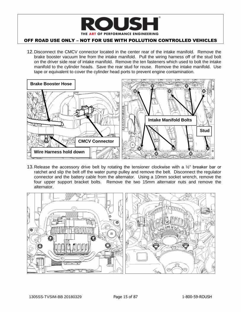
12. Disconnect the CMCV connector located in the center rear of the intake manifold. Remove the brake booster vacuum line from the intake manifold. Pull the wiring harness off of the stud bolt on the driver side rear of intake manifold. Remove the ten fasteners which used to bolt the intake manifold to the cylinder heads. Save the rear stud for reuse. Remove the intake manifold. Use tape or equivalent to cover the cylinder head ports to prevent engine contamination.
13. Release the accessory drive belt by rotating the tensioner clockwise with a ½“ breaker bar or ratchet and slip the belt off the water pump pulley and remove the belt. Disconnect the regulator connector and the battery cable from the alternator. Using a 10mm socket wrench, remove the four upper support bracket bolts. Remove the two 15mm alternator nuts and remove the alternator.
Brake Booster Hose
Wire Harness hold down
Stud
Intake Manifold Bolts
CMCV Connector

OFF ROAD USE ONLY – NOT FOR USE WITH POLLUTION CONTROLLED VEHICLES
1305SS-TVSIM-BB 20180329 Page 16 of 87 1-800-59-ROUSH
14. 2005 – 06 VEHICLES ONLY - Remove the upper radiator and bypass circuit hoses. Remove the clamps from the upper radiator hose and save for later use. On the back side of the water crossover, disconnect the heater hose. Remove the water crossover using a 10mm socket wrench.
14. 2007 – 09 VEHICLES ONLY - Remove the upper radiator hose. On the back side of the water crossover, disconnect the heater hose. Remove the water crossover using a 10mm socket wrench.
Heater Hose
Upper Rad Hose
Thermostat Hose
Crossover Tube Bolts
Upper Rad. Hose
Heater Hose
Crossover Tube Bolts

OFF ROAD USE ONLY – NOT FOR USE WITH POLLUTION CONTROLLED VEHICLES
1305SS-TVSIM-BB 20180329 Page 17 of 87 1-800-59-ROUSH
15. Disconnect the rubber portion of the heater hoses from the metal tubes at the rear of the right-
hand cylinder head. Remove the heater tube assembly from the engine by removing the stud on the back side of the passenger cylinder head and sliding off the water pump fitting in the block.
16. 2005 – 06 VEHICLES ONLY - Locate the coolant hose hanger on the front of the engine and remove.
Disconnect Heater Hoses Here
Stud Bolt

OFF ROAD USE ONLY – NOT FOR USE WITH POLLUTION CONTROLLED VEHICLES
1305SS-TVSIM-BB 20180329 Page 18 of 87 1-800-59-ROUSH
17. Remove the tensioner and retain the bolts for reuse later.

OFF ROAD USE ONLY – NOT FOR USE WITH POLLUTION CONTROLLED VEHICLES
1305SS-TVSIM-BB 20180329 Page 19 of 87 1-800-59-ROUSH
SECTION B - MODIFICATIONS The following section will guide you through the required modifications of existing components and build up of the assemblies used to complete the installation. With the exception of the intercooler pump bracket mounting, all of this work can be performed away from the vehicle.
Alternator Modification
In order for the alternator to be installed in its new location, two of the original mounting ears must be removed. Using a band saw or similar cutting tool, remove the mounting ears shown. Be careful to avoid getting debris inside of the alternator when removing these features. 2005-08 Alternators should look similar to the pictures below:
2009 Alternators should look similar to the pictures below once mounting ears have been removed:
Before After

OFF ROAD USE ONLY – NOT FOR USE WITH POLLUTION CONTROLLED VEHICLES
1305SS-TVSIM-BB 20180329 Page 20 of 87 1-800-59-ROUSH
VMV Modification
1. Remove split loom convolute from stock VMV hose assembly.
2. Mark hose at 130mm (~5.25in) from end of straight connector.
3. Using a knife, cut the hose at the applied mark.
130 mm

OFF ROAD USE ONLY – NOT FOR USE WITH POLLUTION CONTROLLED VEHICLES
1305SS-TVSIM-BB 20180329 Page 21 of 87 1-800-59-ROUSH
4. Using a knife, cut the hose as shown to remove the straight connector from the cut off piece of
VMV hose.
5. Re-install straight connector into shortened VMV hose.
6. Using a knife, cut off 100mm (~4 in) of split loom convolute to fit the shortened VMV line. Re-install the split loom convolute onto the modified VMV hose.

OFF ROAD USE ONLY – NOT FOR USE WITH POLLUTION CONTROLLED VEHICLES
1305SS-TVSIM-BB 20180329 Page 22 of 87 1-800-59-ROUSH
Brake Booster Hose Modification
Note: This modification does not require removal of the hose from the booster.
Removing the hose from the booster could damage the booster fitting.
1. Remove the split loom convolute from brake booster hose. Remove the T-fitting with the 7/32” vacuum hose and the short hose from the brake booster hose assembly.
2. Remove and keep T-fitting with the 7/32” vacuum hose and hose clamp from the take off brake booster hose. Discard short section of the brake booster hose.
3. Remove and discard the 7/32” vacuum hose retaining clip. Measure and mark 45mm from the
end of the 7/32” vacuum hose. Use a knife to cut the vacuum hose at mark.
Discard
Discard

OFF ROAD USE ONLY – NOT FOR USE WITH POLLUTION CONTROLLED VEHICLES
1305SS-TVSIM-BB 20180329 Page 23 of 87 1-800-59-ROUSH
4. Mark the brake booster hose 80mm from end. Using a knife, cut the brake booster hose at the applied mark.
5. Re-install T-fitting with the 7/32 vacuum hose onto the cut brake booster hose.
6. Install the 80mm piece of hose, which was cut off in step 3, on the open end of T-fitting.
OFF ROAD USE ONLY – NOT FOR USE WITH POLLUTION CONTROLLED VEHICLES
1305SS-TVSIM-BB 20180329 Page 24 of 87 1-800-59-ROUSH
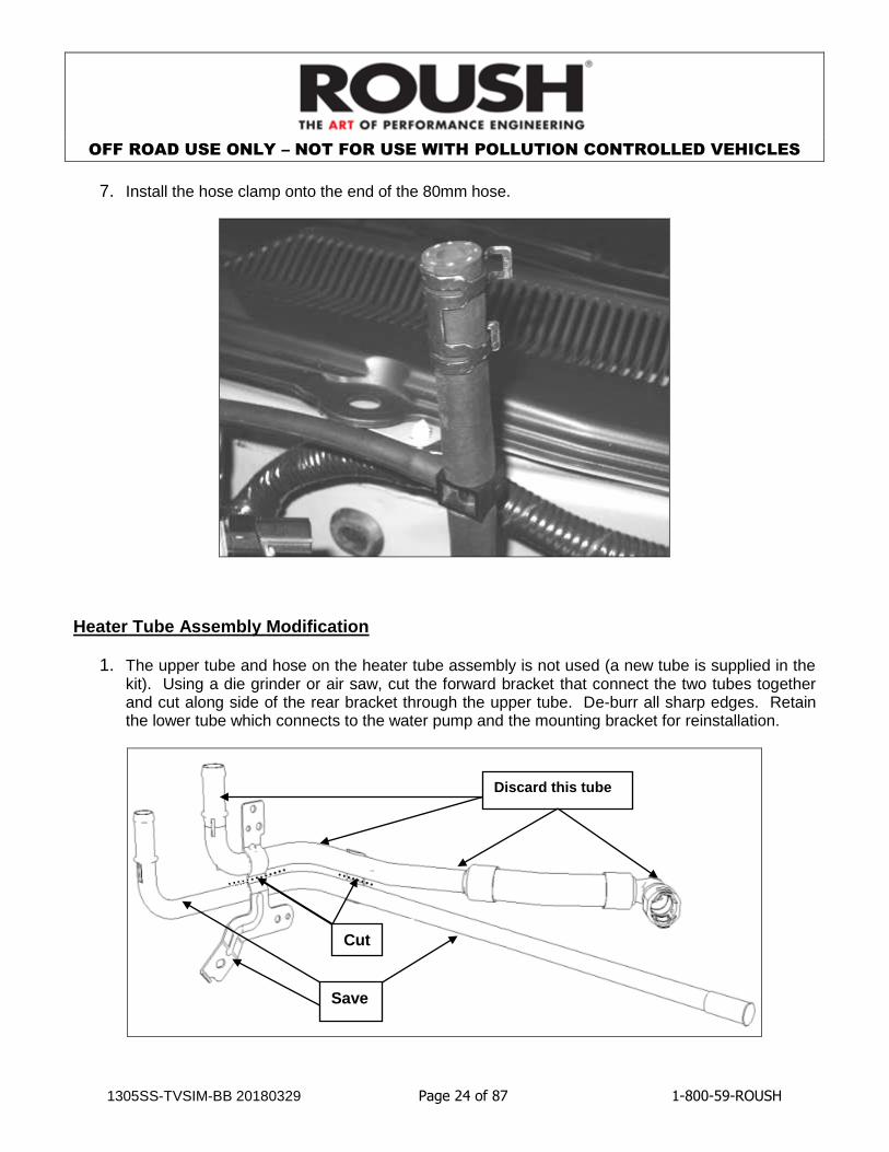
7. Install the hose clamp onto the end of the 80mm hose.
Heater Tube Assembly Modification
1. The upper tube and hose on the heater tube assembly is not used (a new tube is supplied in the kit). Using a die grinder or air saw, cut the forward bracket that connect the two tubes together and cut along side of the rear bracket through the upper tube. De-burr all sharp edges. Retain the lower tube which connects to the water pump and the mounting bracket for reinstallation.
Cut
Discard this tube
Save

OFF ROAD USE ONLY – NOT FOR USE WITH POLLUTION CONTROLLED VEHICLES
1305SS-TVSIM-BB 20180329 Page 25 of 87 1-800-59-ROUSH
Wiring Harness Modifications
The following details the modifications to the factory engine harness which are necessary to complete the installation of this kit. These modifications should be done without removing the harness from the engine as it will be easier to verify final locations of the break out points. Extreme care must be taken to insure that wiring and/or its insulation is not accidentally damaged while removing the convoluted tubing. All of the convoluted tubing and various clips that are removed while making these changes are intended to be reinstalled in the same place unless otherwise noted.
Connectors for Wiring Circuits that will need to be modified
ETC
MAF
TPS

OFF ROAD USE ONLY – NOT FOR USE WITH POLLUTION CONTROLLED VEHICLES
1305SS-TVSIM-BB 20180329 Page 26 of 87 1-800-59-ROUSH
1. Make a note of the locations of the harness retaining clips and breakout points. With the harness still fastened to the engine with the factory retainers, carefully cut the tape off of the convoluted tubing and wiring harness on the drivers side of the engine (where the ETC branches out of the main harness) using a razor or utility knife. The area is highlighted in the following diagram. The convoluted tubing is split from the factory so follow the split. Lift the wiring out of the convoluted tubing without disturbing the factory retainers wherever possible. Expose all of the internal wiring from the MAF/ETC split all the way around to the rear of the driver side cam cover.
2. Locate the 6-wire MAF sensor connector. Looking into the face of the connector with the release tab positioned up, the first two wires in the connector (IAT) from the right are grey and grey w/ red tracer. Cut both of these wires approximately 5 to 6 inches from the back of the connector.
Pull wiring out from this section.

OFF ROAD USE ONLY – NOT FOR USE WITH POLLUTION CONTROLLED VEHICLES
1305SS-TVSIM-BB 20180329 Page 27 of 87 1-800-59-ROUSH
3. Seal the connector side of both cut IAT wires with pieces of heat shrink provided in the ACT electrical jumper (1104-12B637-BA). Place two pieces of heat shrink tubing halfway onto the ends of the wires to be sealed and heat with a heat gun until it stops shrinking and sealant flows out from the open end of the tubing.
4. Drag the 2 IAT wires out of the harness back from the MAF connector so that they break out 60mm past the #6 Coil Connector. Strip a ¼ inch of insulation from the end of each wire. Slide a short length of heat shrink tubing over both wires. Now using the Electrical Jumper (ACT) from the kit (1104-12B637-BA) lay the striped end of the Gray (IAT) wire into one side of the provided splice connector. From the Electrical Jumper (ACT) slide the ACT SIGNAL wire into the other side of the splice connector, and crimp using a W type crimping tool. Using a clean hot soldering iron, heat the wires (not the solder) in the splice connector until they are hot enough to melt the solder touched to them. Repeat the above for the IATRTN – ACT GROUND. Slide the heat shrink tubing over the solder joints and heat to shrink with a heat gun. Position the ACT harness so that the base of the connector is 180mm from the main bundle. Wrap ACT and MAF harness with tape.
Sealing cut wire ends with Heat Shrink tubing
ACT Wire breakout point
#6 Coil

OFF ROAD USE ONLY – NOT FOR USE WITH POLLUTION CONTROLLED VEHICLES
1305SS-TVSIM-BB 20180329 Page 28 of 87 1-800-59-ROUSH
5. Pull the 2-wire ETC (electronic throttle control) wiring loose from the main harness and drag it back to 20mm past the #8 coil break out point. Position the ETC connector so that the base of the connector is 165mm from the main bundle.
6. Slide the driver side of the harness back into its convoluted tubing and re-tape. Wrap the ECT wiring with tape.
7. Move the front (2) harness retainers on driver’s side coil harness from the bottom side to the top side of the harness leaving the rear retainer on the bottom side. Remove the harness to intake manifold stud clip and re-tape it to the harness 210mm from the left valve cover rear retainer.
8. Locate the TPS (Throttle position sensor) connector and harness at the front of the passenger side. Remove the split loom convolute and tape from this harness until the main bundle.
9. Stagger cut the 4 TPS wires 60, 90, 120 and 150mm from the TPS connector. Use the supplied TPS extension harness (R07080031-13-AA) to lengthen the TPS wires using the same technique outlined in step #4. Cover the extend harness with the supplied convolute and run it along with the main harness, securing it to the main harness with tape every 150mm to a position 30mm before the rear intake manifold wire retainer.
Wiring Modification Summary
New Location (Step #4)
New Location (Step #5)
New Location (Steps #8-9)
New Location (Step #7)
New Orientation On Top (Step #7)

OFF ROAD USE ONLY – NOT FOR USE WITH POLLUTION CONTROLLED VEHICLES
1305SS-TVSIM-BB 20180329 Page 29 of 87 1-800-59-ROUSH
Fuel System Modification (This section only to be completed by Phase #2 Customers)
1. Using the Ford Racing installation manual “M-9407-GT05” which is located at the end of this manual in Appendix A, install the Ford Racing GT500 Fuel System Upgrade Kit (R14020001). These instructions can also be found on the internet at: www.fordracingparts.com/download/instructionsheets/FordInstShtM-9407-GT05.pdf
2. Use (2) M6 nuts (W520412) to secure the new fuel pump driver module to an existing stud in the trunk as per the Ford installation manual.
Cylinder Head Modification
1. Cut out the following template. Line up the template with the front of the right hand cylinder head. Using a grinder with a sanding pad attachment, sand down the front corner of the cylinder head up to the template. Take special care that no shavings enter the engine cylinders. Thoroughly clean engine upon completion of this modification.
MODIFY HEAD IN THIS AREA
BEFORE AFTER
TEMPLATE

OFF ROAD USE ONLY – NOT FOR USE WITH POLLUTION CONTROLLED VEHICLES
1305SS-TVSIM-BB 20180329 Page 30 of 87 1-800-59-ROUSH
This page is intentionally left blank.

OFF ROAD USE ONLY – NOT FOR USE WITH POLLUTION CONTROLLED VEHICLES
1305SS-TVSIM-BB 20180329 Page 31 of 87 1-800-59-ROUSH
SECTION C - SUBASSEMBLY
Induction System
1. Install the stock MAF sensor using (2) M4 x 0.7 x 10 MAF bolts (R07130007) into the new clean air tube (R07060101). Torque bolts to 3 – 5Nm.
2. Install the clean air tube bracket (R07130010) on the clean air tube and position using the alignment marks on both the bracket and the tube. Secure the bracket to the tube using (1) M6 x 1.0 x 14 bolt (N605771) supplied in the kit. Apply medium strength thread locker to bolt threads prior to installation and torque to 8 – 12 Nm.
3. Install the air filter (R07060131) to the clean air tube and align the metal strip on the air filter with the alignment mark on the clean air tube. Torque the worm drive clamp to 3 Nm.
MAF bolts
Factory MAF Sensor
Clean air tube

OFF ROAD USE ONLY – NOT FOR USE WITH POLLUTION CONTROLLED VEHICLES
1305SS-TVSIM-BB 20180329 Page 32 of 87 1-800-59-ROUSH
4. Install rubber Grommet and Sleeve Assembly (R07130013) by first installing the rubber grommet into the Shelby Air Box Assembly (R07130039). Once the grommet is firmly seated in position, re-install the metal sleeve into the grommet.
5. Assemble the air tube and filter onto the air box housing using (2) bolts (N605771) and torque to 8 – 12 Nm.
Sleeve
Rubber grommet

OFF ROAD USE ONLY – NOT FOR USE WITH POLLUTION CONTROLLED VEHICLES
1305SS-TVSIM-BB 20180329 Page 33 of 87 1-800-59-ROUSH
S/C Pulley Install
1. Install the S/C Pulley onto the Supercharger (P51AGH-6F066) using the six (6) N605771 bolts (M6 x 14) provided. Ensure the pulley is properly seated on the hub before tightening any bolts. Torque bolts to 8-12 Nm.
Fuel Rail Assembly
1. Install the new injector clips (13109C995) onto the new Fuel Injectors (R07110007) from Hardware Kit B. Apply assembly lube to the injector O-rings and install the injectors into the new Fuel Rail (R07110006). Verify that the injector clips are properly seated and fully engaged into the fuel rail injector cups.
Fuel Charging
1. Install the PCV Bubbler Hose (R07060175) onto the Fuel Charging Assembly (R07060135) and secure it using (1) of the supplied PCV Bubbler clamps.
R07060175 BUBBLER HOSE
R07060135 MANIFOLD ASY
FUEL CHARGING

OFF ROAD USE ONLY – NOT FOR USE WITH POLLUTION CONTROLLED VEHICLES
1305SS-TVSIM-BB 20180329 Page 34 of 87 1-800-59-ROUSH
SECTION D - ASSEMBLY The following section will guide you through the final installation of the kit into the vehicle. If you need to stop during any part of the installation, make sure you cover any open ports in the cylinder heads or intake manifold to prevent foreign material from contaminating your engine.
Intercooler Reservoir Mounting
1. Using the Intercooler Degas Bottle (R07070007) with Degas Bottle Cap (XL3Z-8100-AA) as a template, place the bottle on the flat part of the electric fan shroud between the power steering reservoir and the engine coolant degas bottle. With the edge of the bottle at the edge of the electric fan shroud, mark the (2) mounting holes with a paint pen and drill two 5/16” holes through the fan shroud.
Mark and Drill here

OFF ROAD USE ONLY – NOT FOR USE WITH POLLUTION CONTROLLED VEHICLES
1305SS-TVSIM-BB 20180329 Page 35 of 87 1-800-59-ROUSH
2. Cut out the following template and use it to mark the third mounting hole and drill to 5/16”.
3. Clean the mating surfaces of the degas bottle and fan shroud with brake cleaner or rubbing alcohol. Peel and stick one side of the Double-Sided Tape (R07030002) provided in Cooling System Hardware Kit, to the underside of the degas bottle.
Mark and drill to 5/16”
Double-Sided Tape

OFF ROAD USE ONLY – NOT FOR USE WITH POLLUTION CONTROLLED VEHICLES
1305SS-TVSIM-BB 20180329 Page 36 of 87 1-800-59-ROUSH
This page is intentionally left blank.

OFF ROAD USE ONLY – NOT FOR USE WITH POLLUTION CONTROLLED VEHICLES
1305SS-TVSIM-BB 20180329 Page 37 of 87 1-800-59-ROUSH
4. Remove the upper fan shroud bolts and force the shroud toward the rear of the vehicle. Install
the (2) J-Clips (N623332) from the Hardware Kit. Peel the second side of the double-sided tape and set the bottle on the fan shroud. Secure the intercooler degas bottle using (2) M6 x 1.0 x 33 bolts (N808429) and the M6 x 1.0 x 8 cap screw (R18020010) with washer (R18030002) from Hardware Kit and torque to 8 – 12Nm. Reinstall the upper fan shroud bolts and torque to 8 – 12Nm.
Intercooler Radiator Assembly Mounting
1. Remove the (6) push pin retainers highlighted below by pulling the center pin and remove the radiator trim cover.
Push Pin retainers

OFF ROAD USE ONLY – NOT FOR USE WITH POLLUTION CONTROLLED VEHICLES
1305SS-TVSIM-BB 20180329 Page 38 of 87 1-800-59-ROUSH
2. Raise the vehicle and remove both front tires. Remove the (3) forward Phillips-head screws
from each front wheel liner. Using a Phillips-head screwdriver, turn the (5) inner fender push pins ¼ turn to release the centers. Remove the pushpins and then remove the forward inner fenders.
3. Remove the (3) lower close-out to radiator support screws (7mm). Remove the (2) upper bumper cover screws near the headlights (10mm). Remove the (4) front fender to bumper cover nuts inside the forward wheel well (10mm).
Close-out screws Fender to Bumper
Cover Nuts
Upper Bumper Cover Screws
Inner Fender Push Pin Locations
3 Phillips head screws

OFF ROAD USE ONLY – NOT FOR USE WITH POLLUTION CONTROLLED VEHICLES
1305SS-TVSIM-BB 20180329 Page 39 of 87 1-800-59-ROUSH
4. Reach inside the front wheel wells and unplug the front turn signals (there are four connectors
total). Lift the front bumper cover slightly and pull partially off of the vehicle. Unplug the fog lights and set the front bumper cover aside.
5. Remove the four push pins that retain the impact absorber to the front bumper beam and set the absorber aside.
6. Remove the inner front bumper beam bolts. Save one bolt for reuse later.
Push Pins
Inner Bumper Bolts

OFF ROAD USE ONLY – NOT FOR USE WITH POLLUTION CONTROLLED VEHICLES
1305SS-TVSIM-BB 20180329 Page 40 of 87 1-800-59-ROUSH
7. Loosely install the (4) Long Bumper Bolts (R18020007) from the Hardware kit in place of the (4)
which were just removed. Insert the Intercooler Radiator Assembly (R07070047) behind the bumper and between the frame rails aligning the holes in the bracket with the weld nuts for the inner bumper bolts. Snug the inner bumper bolts threading them through the bracket holes and torque to 20 – 30 Nm. Install the (4) LTR Mounting Nuts (W520413) from the Hardware Kit on the exposed end of the long bumper bolts and torque to 20 – 30 Nm.
8. Reinstall the impact absorber onto the front bumper beam using the take out pushpins.
9. Install the 12 ½” LTR Inlet Hose on the driver side of LTR with one ¾” Hose Clamp and leave hanging. Install the 33 ¾” LTR Outlet Hose on the passenger side of the LTR with one ¾” Hose Clamp and route up through the fender and into the engine compartment as illustrated below.
Intercooler Radiator Assembly
Retaining Nut
Inner Bumper Bolt

OFF ROAD USE ONLY – NOT FOR USE WITH POLLUTION CONTROLLED VEHICLES
1305SS-TVSIM-BB 20180329 Page 41 of 87 1-800-59-ROUSH
Electric Water Pump Bracket Mounting
1. Cut out the following template. Line up the template with the tie down bracket inside the driver side wheel well. Center punch the “X”s marked on the template into the frame rail of the vehicle. Drill two ¼” holes through the frame rail and de-burr the holes.
2. Install (2) J-Clips (N623332) from Hardware Kit and mount the Intercooler Pump Mounting Bracket (R07070015) using Bolts (N605891) onto the body. Torque bolts to 8 – 12Nm. Slide the Intercooler Pump (F8YZ-8501-AA) into the bracket and secure using the bumper bolt removed earlier and a M8 Nut (W520413) from Hardware Kit. Torque the nut and bolt to 8 – 12Nm.
Cut this out and use as a template to locate holes
Use take off
bumper bolt in
this location

OFF ROAD USE ONLY – NOT FOR USE WITH POLLUTION CONTROLLED VEHICLES
1305SS-TVSIM-BB 20180329 Page 42 of 87 1-800-59-ROUSH
This page is intentionally left blank.
OFF ROAD USE ONLY – NOT FOR USE WITH POLLUTION CONTROLLED VEHICLES
1305SS-TVSIM-BB 20180329 Page 43 of 87 1-800-59-ROUSH
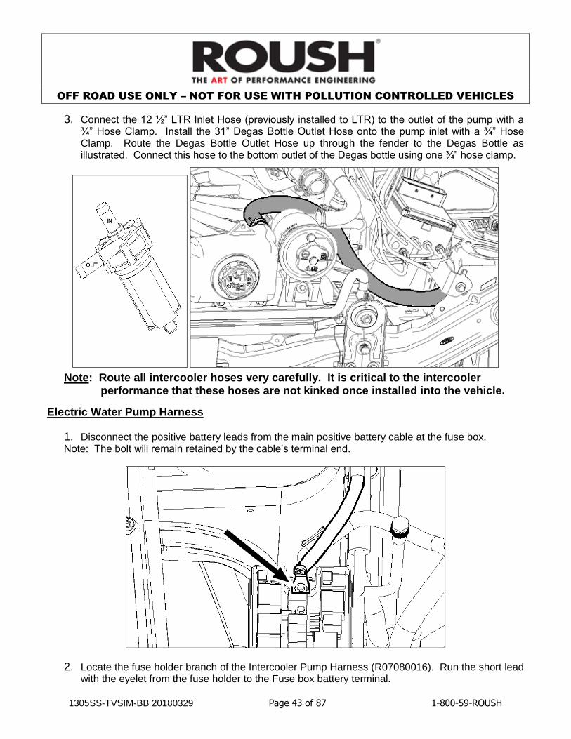
3. Connect the 12 ½” LTR Inlet Hose (previously installed to LTR) to the outlet of the pump with a ¾” Hose Clamp. Install the 31” Degas Bottle Outlet Hose onto the pump inlet with a ¾” Hose Clamp. Route the Degas Bottle Outlet Hose up through the fender to the Degas Bottle as illustrated. Connect this hose to the bottom outlet of the Degas bottle using one ¾” hose clamp.
Note: Route all intercooler hoses very carefully. It is critical to the intercooler performance that these hoses are not kinked once installed into the vehicle.
Electric Water Pump Harness
1. Disconnect the positive battery leads from the main positive battery cable at the fuse box. Note: The bolt will remain retained by the cable’s terminal end.
2. Locate the fuse holder branch of the Intercooler Pump Harness (R07080016). Run the short lead with the eyelet from the fuse holder to the Fuse box battery terminal.

OFF ROAD USE ONLY – NOT FOR USE WITH POLLUTION CONTROLLED VEHICLES
1305SS-TVSIM-BB 20180329 Page 44 of 87 1-800-59-ROUSH
3. Reinstall the battery cable bolt through the I/C fuse lead and the main battery cable. Torque the bolt to 8 – 12Nm.
4. Secure the fuse holder to the strut tower using a M6 x 1.0 x 14 bolt (N605771) from Hardware kit threaded into the tapped hole in the strut tower across from the fuse box’s main battery terminal. Torque bolt to 8 – 12 Nm.
5. Route the remaining I/C pump harness with the vehicle harness around the driver side of the PCM bracket to the space ahead of the PCM connectors.
6. Locate the M6 bolt threads protruding from the core support into the engine compartment ahead of the PCM brackets. Slide the I/C pump relay’s bracket over this stud and secure with a M6 nut (W520412). Torque the nut to 8 – 12Nm.
Front of Vehicle
6mm Bolt threads

OFF ROAD USE ONLY – NOT FOR USE WITH POLLUTION CONTROLLED VEHICLES
1305SS-TVSIM-BB 20180329 Page 45 of 87 1-800-59-ROUSH
7. Route the ground wire branch of the harness up to the ground screw directly above the relay. Remove the ground screw and install the I/C Pump ground wire with all the factory grounds that were already in place with the bolt. Torque the bolt to 8 – 12Nm.
8. Locate the square 16-pin connector on the driver side of the PCM bracket. Unplug the connector and remove the short section of convoluted tubing and electrical tape from the harness immediately behind the engine side (rearward half as mounted) of the connector. Locate the red w/yellow stripe wire in pin location #16. Cut this red wire about 1 inch back from the connector.
16-pin connector
Red/yellow stripe - #16

OFF ROAD USE ONLY – NOT FOR USE WITH POLLUTION CONTROLLED VEHICLES
1305SS-TVSIM-BB 20180329 Page 46 of 87 1-800-59-ROUSH
9. Seal the connector end of the red wire using one piece of heat shrink provided with the Intercooler Pump Wiring Harness Kit (R07080016).
10. Strip approximately 3/8” of insulation off the harness side of the red w/yellow wire. Place a piece of supplied heat shrink tubing over the remaining, non-terminated end of the Intercooler Pump Wiring Harness. Strip approximately 3/8” of insulation off the end of the intercooler wire and connect to the red wire using the provided splice connector from the Intercooler Pump Wiring Harness Kit and crimp using a W-type crimping tool. Using a clean, hot soldering iron, heat the wires (not the solder) in the splice connector until they are hot enough to melt the solder touched to them. Slide the heat shrink tubing over the solder joint and heat to shrink with a heat gun. Reinstall the convoluted tubing and tape removed from the factory harness.
Sealing cut wire ends with Heat Shrink tubing

OFF ROAD USE ONLY – NOT FOR USE WITH POLLUTION CONTROLLED VEHICLES
1305SS-TVSIM-BB 20180329 Page 47 of 87 1-800-59-ROUSH
11. Plug the connector back together. Route the remainder of the Intercooler Pump Wiring Harness over the radiator (following the existing harness) behind the headlamp on the driver side and into the inner fender area where the water pump bracket is mounted. Remove the top water pump bracket mounting bolt and install the wiring harness ground eyelet and re-torque the fastener. Connect the wiring harness to the electric water pump.
Ground the pump wiring harness to the
body in this location.

OFF ROAD USE ONLY – NOT FOR USE WITH POLLUTION CONTROLLED VEHICLES
1305SS-TVSIM-BB 20180329 Page 48 of 87 1-800-59-ROUSH
Lower Radiator Hose Installation
1. 2005 – 06 VEHICLES ONLY – Install the Lower Radiator Hose (7R33-8B273-AA) by sliding the hose onto the outlet at the bottom corner of the radiator. Then push the hose on to the fitting on the oil filter adapter. Connect the smaller hose to the bottom of the degas bottle. Secure each point with the clamps that are glued onto the hose.

OFF ROAD USE ONLY – NOT FOR USE WITH POLLUTION CONTROLLED VEHICLES
1305SS-TVSIM-BB 20180329 Page 49 of 87 1-800-59-ROUSH
Engine Hardware and ROUSHCharger Installation
1. Using the take off bolts, install the FEAD tensioner (R07020043). Torque bolts to 20 – 30 Nm.
2. Remove the factory spark plugs and coils from the engine. NOTE: Customers with 2005 - 07 vehicles and 2008 vehicles (with AA level engines only) use the supplied 14mm plugs (HTO-032). Customers with 2008 vehicles (with AB level engines) and customers with 2009 vehicles with 12mm plugs (Ford P/N: 8L3E-12405-BB) must gap their factory spark plugs to 0.032 +/- 0.002”.
3. Install either the newly supplied HTO-032 plugs (14mm plugs) or regapped (12mm plugs) depending on your engine configuration. Torque 14mm plugs to 30 – 38 Nm. Torque 12mm plugs to 10 – 15 Nm.
4. Reinstall the coils and torque coil bolts to 4 – 6 Nm.

OFF ROAD USE ONLY – NOT FOR USE WITH POLLUTION CONTROLLED VEHICLES
1305SS-TVSIM-BB 20180329 Page 50 of 87 1-800-59-ROUSH
5. Install the modified heater tube assembly using the take out stud bolt. Be sure to lube the O-rings with assembly lube before installing the heater tube to the water pump fitting in the block. Torque the stud to 8 – 12 Nm.
6. Carefully place the intake manifold assembly (with gaskets) down onto the cylinder heads. Be carefully not to damage your sealing surfaces or gaskets during this step. Take special care to ensure that the CHT wiring harness does not get pinched or trapped during manifold installation. Insert (2) M6 x 1.0 x 40 bolts (R18020004) in holes A and B as shown and start threads by hand. Do NOT tighten these fasteners. The intake must remain free to move along the cylinder head surfaces.
A B

OFF ROAD USE ONLY – NOT FOR USE WITH POLLUTION CONTROLLED VEHICLES
1305SS-TVSIM-BB 20180329 Page 51 of 87 1-800-59-ROUSH
7. Install the Alternator Bracket (R07020035) onto the studs previously used to mount the alternator to the cylinder block and temporarily secure the bracket using the stock nuts. Use the FEAD bracket rear mounting bosses to properly align the intake manifold on the cylinder head surfaces by shifting the manifold from front to back and side to side. When you are finished, these features should be aligned in both the for-aft and side-to-side directions.
8. Once aligned, fasten the intake manifold using (11) M6 x 1.0 x 40 supplied bolts (R18020004) and the stock driver side rear stud in hole #10 (used to retain the wiring harness). Tighten these fasteners in the sequence shown below and torque all to 8 – 12 Nm. Remove the alternator bracket from the engine as it will be installed in a later step.
2
1
4
5
6 8
9 11
12
10 (STUD)
3 7

OFF ROAD USE ONLY – NOT FOR USE WITH POLLUTION CONTROLLED VEHICLES
1305SS-TVSIM-BB 20180329 Page 52 of 87 1-800-59-ROUSH
9. Fasten the supercharger to the intake manifold using (8) M8 x 1.25 x 56 bolts (N808130) and (2) M6 x 15 / M8 x 53 studs (R18040007) in holes #1 and #5. Torque fasteners in three steps; 10Nm, 20Nm and 30Nm in the sequence shown.
10. Connect the PCV bubbler hose to the 90 deg fitting on the back of the supercharger using (1) of the supplied 3/8” constant tension clamps.
3 7
8
10
1 5 9
6 4 2

OFF ROAD USE ONLY – NOT FOR USE WITH POLLUTION CONTROLLED VEHICLES
1305SS-TVSIM-BB 20180329 Page 53 of 87 1-800-59-ROUSH
11. Re-install the FEAD bracket using (2) take off M8 nuts for mounting to old alternator studs, (2) M8 x 1.25 x 38 bolts (W705128) for fastening to the upper intake manifold and (1) M8 x 1.25 x 110 bolt (R18020058) with (1) spacer (R18030017) to fasten to the supercharger. First hand tighten every bolt, then torque the M8 nuts to 20 – 30 Nm, then torque the middle M8 bolts to 20 – 30 Nm, then finally torque the top M8 bolt to 20 – 30 Nm.
12. Install the (2) FEAD Pulleys (R07020049) to the alternator bracket using the (2) M8x1.25x32 Idler Bolts (R18020060). Torque bolts to 20 – 30Nm.
R07020049 76MM IDLER
R18020060 (M8X1.25X28mm)
TORQUE 20-30 Nm 2 REQ’D
R18030017 Spacer

OFF ROAD USE ONLY – NOT FOR USE WITH POLLUTION CONTROLLED VEHICLES
1305SS-TVSIM-BB 20180329 Page 54 of 87 1-800-59-ROUSH
13. Lubricate the fuel injector o-rings with 5W-20 engine oil. Apply a small amount of engine oil to the injector pockets in the intake manifold and install the fuel rail and injector assembly. Be sure each injector is properly seated into the intake manifold. Secure the fuel rail using (2) take out studs on the driver’s side and (2) M6 x 1.0 x 22mm bolts (R18020057) on the passenger side. Torque bolts to 8 – 12 Nm.
14. Install the 7/32” vacuum hose (R18140001) from the IPTS on the fuel rail to the fitting in the upper intake manifold.
R18140001 VACUUM HARNESS

OFF ROAD USE ONLY – NOT FOR USE WITH POLLUTION CONTROLLED VEHICLES
1305SS-TVSIM-BB 20180329 Page 55 of 87 1-800-59-ROUSH
Charge Harness and Wiring Installation
1. 2005 – 08 VEHICLES ONLY – Slide the smart charge harness (R07080033) underneath the front cover of the supercharger behind the FEAD bracket so that the round connector is on the passenger side of the engine. (2009 Vehicles – please refer to Section E on Page 79)
2. 2005 – 08 VEHICLES ONLY – Connect the alternator smart charge harness by routing the harness as shown. (2009 Vehicles – please refer to Section E on Page 79)

OFF ROAD USE ONLY – NOT FOR USE WITH POLLUTION CONTROLLED VEHICLES
1305SS-TVSIM-BB 20180329 Page 56 of 87 1-800-59-ROUSH
3. Connect injector #1 – 4 and coil #1 – 3.
4. Move the main harness on top of coil #4 and plug in coil #4 around it.
5. Pull the main harness below the rear intercooler turret.

OFF ROAD USE ONLY – NOT FOR USE WITH POLLUTION CONTROLLED VEHICLES
1305SS-TVSIM-BB 20180329 Page 57 of 87 1-800-59-ROUSH
6. Drape the TPS harness breakout in-between the driver side fuel rail and the supercharger.
7. Install the rear harness retaining clip on the stud in the back of the intake manifold.

OFF ROAD USE ONLY – NOT FOR USE WITH POLLUTION CONTROLLED VEHICLES
1305SS-TVSIM-BB 20180329 Page 58 of 87 1-800-59-ROUSH
8. Push the two retaining clips onto the studs on the LH cam cover. Connect injectors #5 – 8 and coils #5 – 8.
9. Route the ACT sensor under the fuel rail in-between injectors #6 and #7 and connect sensor.

OFF ROAD USE ONLY – NOT FOR USE WITH POLLUTION CONTROLLED VEHICLES
1305SS-TVSIM-BB 20180329 Page 59 of 87 1-800-59-ROUSH
10. Connect the IPTS.
11. 2005 – 08 VEHICLES ONLY – Route the B+ cable (R07080032) under the main harness in-between the VCT solenoid and coil #5. (2009 Vehicles – please refer to Section E on Page 79)

OFF ROAD USE ONLY – NOT FOR USE WITH POLLUTION CONTROLLED VEHICLES
1305SS-TVSIM-BB 20180329 Page 60 of 87 1-800-59-ROUSH
12. 2005 – 08 VEHICLES ONLY – Push the B+ cable retainers onto the fuel rail studs. (2009 Vehicles – please refer to Section E on Page 79)
13. 2005 – 08 VEHICLES ONLY – Remove the (2) plastic fasteners that hold the cowl grill in place. Lift the cowl grill for easier access to replace the factory screw that secures the grounding strap to the cowl with (1) M6 x 1.0 x 18.5mm bolt (N605891) at the arrow shown. Torque bolt to 8 – 12Nm and replace plastic fasteners. (2009 Vehicles – please refer to Section E on Page 79)
Remove plastic fasteners
Insert new bolt here

OFF ROAD USE ONLY – NOT FOR USE WITH POLLUTION CONTROLLED VEHICLES
1305SS-TVSIM-BB 20180329 Page 61 of 87 1-800-59-ROUSH
14. 2005 – 08 VEHICLES ONLY – Route the B+ cable through the grounding strap and secure it to the dash using (1) Stud Mount Zip Tie (R18080003). Push the Zip Tie onto the M6 Bolt from the previous step then wrap the zip tie around the cable. (2009 Vehicles – please refer to Section E on Page 79)
15. 2005 – 08 VEHICLES ONLY – Secure the B+ cable to the dash by pushing the retainer (Christmas tree) to the factory dash panel tab. (2009 Vehicles – please refer to Section E on Page 79)

OFF ROAD USE ONLY – NOT FOR USE WITH POLLUTION CONTROLLED VEHICLES
1305SS-TVSIM-BB 20180329 Page 62 of 87 1-800-59-ROUSH
16. Using the take off M8 nut, fasten the driver side radio suppressor to the driver side front cover stud. Before tightening, ensure there is sufficient clearance to all FEAD components. Torque to 23 – 27Nm. Use a screwdriver to bend the tab around the back of the stud.
17. Using the take off M8 nut, fasten the passenger side radio suppressor to the passenger side front cover stud. Before tightening, ensure there is sufficient clearance to all FEAD components. Torque nut to 23 – 27 Nm. Bend the tab around the back of the stud.

OFF ROAD USE ONLY – NOT FOR USE WITH POLLUTION CONTROLLED VEHICLES
1305SS-TVSIM-BB 20180329 Page 63 of 87 1-800-59-ROUSH
18. 2005 – 08 VEHICLES ONLY - Insert (2) M8 x 1.25 x 55 bolts (N808130) and (2) M8 nuts (W520413) through the alternator bracket. Be sure to leave enough room to insert the alternator. Slide the alternator onto the bolts. Ensure that the smart charge harness does not get pinched. Torque to 20 – 30 Nm. (2009 Vehicles – please refer to Section E on Page 79)
19. 2005 – 08 VEHICLES ONLY - Install the Rear Alternator Support Bracket (R07020045) using the M8 x 1.25 x 20mm bolt (R18020005) into the alternator and M8 x 1.25 x 25mm bolt (W500224) into the intake. Route the B+ cable in-between this bracket and the alternator. Torque bolts to 20 – 30 Nm. (2009 Vehicles – please refer to Section E on Page 79)
WARNING: Do not put any bolt longer than 20mm into the back of the alternator.
R18020005
20mm MAX Length
W500224
Route B+ Cable under this bracket

OFF ROAD USE ONLY – NOT FOR USE WITH POLLUTION CONTROLLED VEHICLES
1305SS-TVSIM-BB 20180329 Page 64 of 87 1-800-59-ROUSH
20. 2005 – 08 VEHICLES ONLY – Connect the B+ cable to the stud on the back of the alternator using the take off nut. Torque to 8 – 12 Nm. Plug in the smart charge harness. Ensure that there are no pinched wires around the alternator. (2009 Vehicles – please refer to Section E on Page 79)
21. Install the FEAD belt as shown. Using a ½” drive breaker bar or ratchet, rotate the belt tensioner clockwise to install the supplied belt.
22. Connect the rubber heater tube inlet hose (R07070067) to the steel heater water inlet tube (R07070063) using (1) ¾” constant tension clamp. Install this assembly onto the engine by connecting the rubber hose to the 90 deg fitting on the intake using (1) constant tension clamp and fasten the steel tube to the supercharger studs using (2) M6 nuts (W520412).

OFF ROAD USE ONLY – NOT FOR USE WITH POLLUTION CONTROLLED VEHICLES
1305SS-TVSIM-BB 20180329 Page 65 of 87 1-800-59-ROUSH
23. Connect the fuel inlet line to the fuel rail and secure it using the safety clip.
24. Install the throttle body spacer gasket (R07060152) and the throttle body gasket (R07060153) in the throttle body spacer (R07060147).

OFF ROAD USE ONLY – NOT FOR USE WITH POLLUTION CONTROLLED VEHICLES
1305SS-TVSIM-BB 20180329 Page 66 of 87 1-800-59-ROUSH
25. Fasten the throttle body spacer to the supercharger using (4) M6 x 1.0 x 32.5 screws (R18020009) and torque to 8 – 12 Nm.
26. Install throttle body onto the throttle body spacer using (4) M6 x 1.0 x 32.5 screws (R18020009). Torque to 8 – 12 Nm.

OFF ROAD USE ONLY – NOT FOR USE WITH POLLUTION CONTROLLED VEHICLES
1305SS-TVSIM-BB 20180329 Page 67 of 87 1-800-59-ROUSH
27. Connect TPS and ETC.
28. Install the PCV purge hose (R07050084) from the driver side cam cover to throttle body spacer.

OFF ROAD USE ONLY – NOT FOR USE WITH POLLUTION CONTROLLED VEHICLES
1305SS-TVSIM-BB 20180329 Page 68 of 87 1-800-59-ROUSH
29. Install the Intercooler Tube Assembly (R07070005) onto the passenger side cylinder head using
the M16 x 40mm Tube Mounting Bolt (R18020006) for the rear and (1) M6 x 1.0 x 18 I/C Tube Mounting Bolt (N605891). Torque the M16 bolt to 43 – 47Nm and the M6 bolt to 8 – 12Nm.
30. Reconnect the stock 5/8” heater hose from the firewall to the modified heater tube located on the rear of the passenger side cylinder head using the original constant tension clamp.
31. Install the ¾” x 190.9mm Intercooler Inlet hose (R07060173) from A to A using (2) ¾” constant tension clamps. Install the ¾” x 286.2mm Intercooler Outlet hose (R07060174) from B to B using (2) ¾” constant tension clamps.
A A
B
B

OFF ROAD USE ONLY – NOT FOR USE WITH POLLUTION CONTROLLED VEHICLES
1305SS-TVSIM-BB 20180329 Page 69 of 87 1-800-59-ROUSH
32. Reconnect the stock 3/4” heater hose from the firewall by routing it under the intercooler hoses and connecting it to the steel heater inlet tube using the original constant tension clamp.
33. Connect the LTR Outlet hose routed from behind the passenger side headlamp to the lower Intercooler tube using (1) constant tension clamp. Install the 17 ½” Degas Inlet hose (R07070006) from the upper intercooler tube, using (1) constant tension clamp #81-B, to the upper degas bottle fitting, using (1) ¾” worm clamp.
34. Install the upper radiator hose (R07070022) using the take off constant tension clamps.

OFF ROAD USE ONLY – NOT FOR USE WITH POLLUTION CONTROLLED VEHICLES
1305SS-TVSIM-BB 20180329 Page 70 of 87 1-800-59-ROUSH
35. Locate the ABS module bracket and remove the bolt shown below.
36. Install the rubber grommets from the bottom of the factory air box into the holes located beneath the air box, rearward of the ABS module.
Remove bolt
ABS module
Installed rubber grommets

OFF ROAD USE ONLY – NOT FOR USE WITH POLLUTION CONTROLLED VEHICLES
1305SS-TVSIM-BB 20180329 Page 71 of 87 1-800-59-ROUSH
37. Lower the air box assembly into the vehicle using the two pegs as guides into the rubber grommets. Loosely secure the air box to the vehicle using the take off air box bolt and the supplied ABS bracket bolt (N808920). Note: Do not torque bolts.
38. Install the 3/16” (4440) and 3/8” (P2333A) fittings into their respective holes on the clean air tube (1305-9B659). Foaming glass cleaner can be used to aid in this step. Place a vacuum cap over each of these fittings (383004 &CS2575), found in Hardware kit R07130040.
ABS bracket bolt
Take-off air box bolt

OFF ROAD USE ONLY – NOT FOR USE WITH POLLUTION CONTROLLED VEHICLES
1305SS-TVSIM-BB 20180329 Page 72 of 87 1-800-59-ROUSH
39. Loosely install the 120-140mm clamp (R07130014) onto the oval end of the clean air tube and the 110-130mm clamp onto the round end of the clean air tube (R07130015). Orient the clamps so both screw heads are facing the same direction of the PCV fitting. Install the clean air tube in the vehicle by first sliding the round end onto the MAF tube then pushing the oval end onto the throttle body. Tighten the throttle body clamp so the screw is close to the ETC motor on the topside of the throttle body. Tighten the MAF tube clamp so the screw is on the bottom side of the tube. Torque both clamps to 3 Nm.
40. Tighten the (2) bolts in the air-box. Torque the M6 bolt to 8 – 12Nm and torque the M8 bolt to 22 – 26Nm.
41. Check induction system to make sure everything is secured and at the required torque specification.
42. Connect the MAF sensor.

OFF ROAD USE ONLY – NOT FOR USE WITH POLLUTION CONTROLLED VEHICLES
1305SS-TVSIM-BB 20180329 Page 73 of 87 1-800-59-ROUSH
43. Install the PCV Fresh Air tube (R07050083), by connecting the 90 deg fitting to the passenger side cam cover and running the tube over the supercharger and connecting the straight fitting to the rubber clean air tube.

OFF ROAD USE ONLY – NOT FOR USE WITH POLLUTION CONTROLLED VEHICLES
1305SS-TVSIM-BB 20180329 Page 74 of 87 1-800-59-ROUSH
Battery and Tray
1. Install the battery tray by reversing the removal instructions. Torque the battery tray bolts to 8 – 12 Nm.
2. Place the battery in the tray and secure with battery hold down. Torque the battery hold down bolt to 8 – 12 Nm. Reinstall the heat protecting battery wrap over the battery.
3. Connect the B+ Alternator Harness to the positive battery terminal. Torque nut to 8 – 12Nm.
4. Reinstall the battery connections by connecting the positive cable first then connecting the negative cable.

OFF ROAD USE ONLY – NOT FOR USE WITH POLLUTION CONTROLLED VEHICLES
1305SS-TVSIM-BB 20180329 Page 75 of 87 1-800-59-ROUSH
Vacuum System Connections
1. Install the modified VMV hose such that the 90 deg. fitting is connected to throttle body spacer and the straight fitting is connected to the VMV’s upper port.

OFF ROAD USE ONLY – NOT FOR USE WITH POLLUTION CONTROLLED VEHICLES
1305SS-TVSIM-BB 20180329 Page 76 of 87 1-800-59-ROUSH
2. Connect the modified brake booster hose assembly onto the throttle body spacer.
3. Connect the 7/32” vacuum hose from the T-fitting to the UPPER fitting on the supercharger bypass valve (this will be the fitting closest to the dash panel). The bottom/lower fitting MUST remain open to atmosphere for the supercharger bypass system to function properly.

OFF ROAD USE ONLY – NOT FOR USE WITH POLLUTION CONTROLLED VEHICLES
1305SS-TVSIM-BB 20180329 Page 77 of 87 1-800-59-ROUSH
Coolant Fill and Final Assembly
1. Fill the engine cooling system (using a proper coolant mixture) to the marked level on the radiator degas bottle.
2. Using the same coolant mixture, fill the intercooler system. The coolant should be
approximately one inch below the top of the cap.
Important: Both coolant systems can trap a large amount of air. It is very important to verify that the air is purged and that coolant is flowing properly through both systems. Roush recommends vacuum filling both systems to properly evacuate the trapped air.
3. Reinstall front bumper cover, lower close-out panel and inner fenders by reversing the removal
procedures.
4. Reinstall the front wheels/tires. Torque wheel lugs to the factory Ford specifications.
5. Inspect all underhood wiring harnesses for potential interference issues. Use zip ties to safely position the harness away from any areas of concern.
6. If the PCM was removed and shipped to ROUSH for a ROUSH performed flash, reinstall it once
the PCM is returned from ROUSH and apply PCM decal (R07100008). If you are equipped with a SAE J2534 pass through device, refer to the PCM Flashing section when installation is complete. DO NOT ATTEMPT TO REINSTALL THE PCM AND START THE VEHICLE IF THE PCM IS NOT EQUIPPED WITH A ROUSH CALIBRATION. OPERATING THE ENGINE WITHOUT THE RECALIBRATED PCM WILL RESULT IN ENGINE DAMAGE OR FAILURE AND WILL VOID THE WARRANTY.
7. Reinstall the battery connections by connecting the positive cable first then connecting the
negative cable.
8. The Belt Routing Diagram (13106E072) is to be placed on the underside of the hood, on the driver side, opposite of the factory Vehicle Emission Control Information decal.
Place Decal Here

OFF ROAD USE ONLY – NOT FOR USE WITH POLLUTION CONTROLLED VEHICLES
1305SS-TVSIM-BB 20180329 Page 78 of 87 1-800-59-ROUSH
9. The “Premium Fuel” clear decal with white lettering (R07110004) is to be installed on the
instrument cluster bezel, on the flat area below the small center gauges.
10. The “Premium Fuel” white decal with black lettering (R07110003) is to be placed on the lower
half of the inside of the fuel filler door.
11. If performing the PCM Flash procedure, proceed to the “PCM Flashing” section. If the PCM was sent to ROUSH for the Optional ROUSH Performed Flash and it has been reinstalled, start the engine and check for unusual noise, dash service lights, and/or unusual operation. If problems are detected, immediately stop the engine or vehicle, diagnose and repair the problem.
Place Decal Here
Place Decal Here
Speedometer Tachometer

OFF ROAD USE ONLY – NOT FOR USE WITH POLLUTION CONTROLLED VEHICLES
1305SS-TVSIM-BB 20180329 Page 79 of 87 1-800-59-ROUSH
PCM FLASHING
1. If equipped with a SAE J2534 pass through device, refer to the RDT-CALIM manual found online at rdt.roush.com (link on main page). The RDT-CALIM manual will guide you through the ROUSH Diagnostic Tool (RDT) software installation process and the ROUSH PCM flashing procedure. OPERATING THE ENGINE WITHOUT THE RECALIBRATED PCM WILL RESULT IN ENGINE DAMAGE OR FAILURE AND WILL VOID THE WARRANTY.
2. Once the PCM has been successfully re-calibrated, start the engine and check for unusual noises, dash service lights, and unusual operation. If problems are detected, immediately stop the engine or vehicle, diagnose and repair the problem.
OFF ROAD USE ONLY – NOT FOR USE WITH POLLUTION CONTROLLED VEHICLES
1305SS-TVSIM-BB 20180329 Page 80 of 87 1-800-59-ROUSH
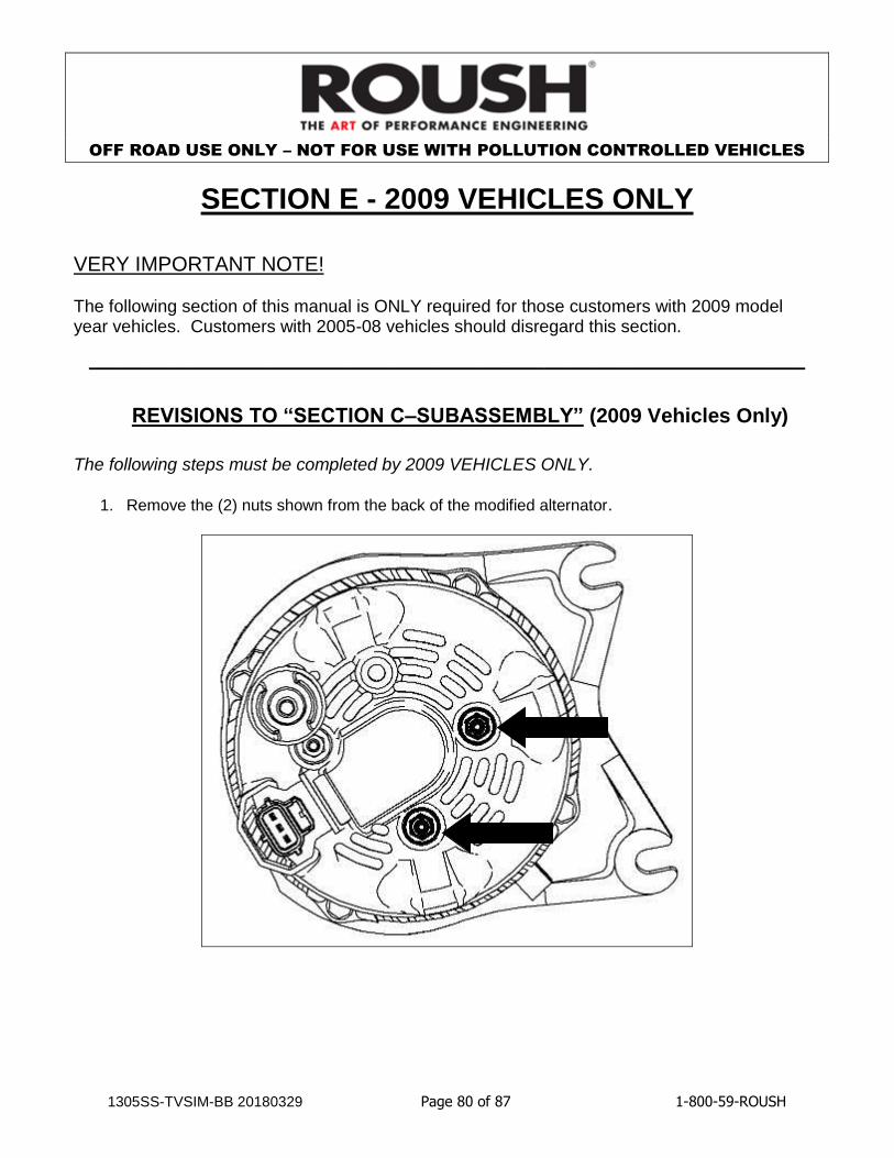
SECTION E - 2009 VEHICLES ONLY
VERY IMPORTANT NOTE! The following section of this manual is ONLY required for those customers with 2009 model year vehicles. Customers with 2005-08 vehicles should disregard this section.
________________________________________________________________________________________
REVISIONS TO “SECTION C–SUBASSEMBLY” (2009 Vehicles Only)
The following steps must be completed by 2009 VEHICLES ONLY.
1. Remove the (2) nuts shown from the back of the modified alternator.
OFF ROAD USE ONLY – NOT FOR USE WITH POLLUTION CONTROLLED VEHICLES
1305SS-TVSIM-BB 20180329 Page 81 of 87 1-800-59-ROUSH
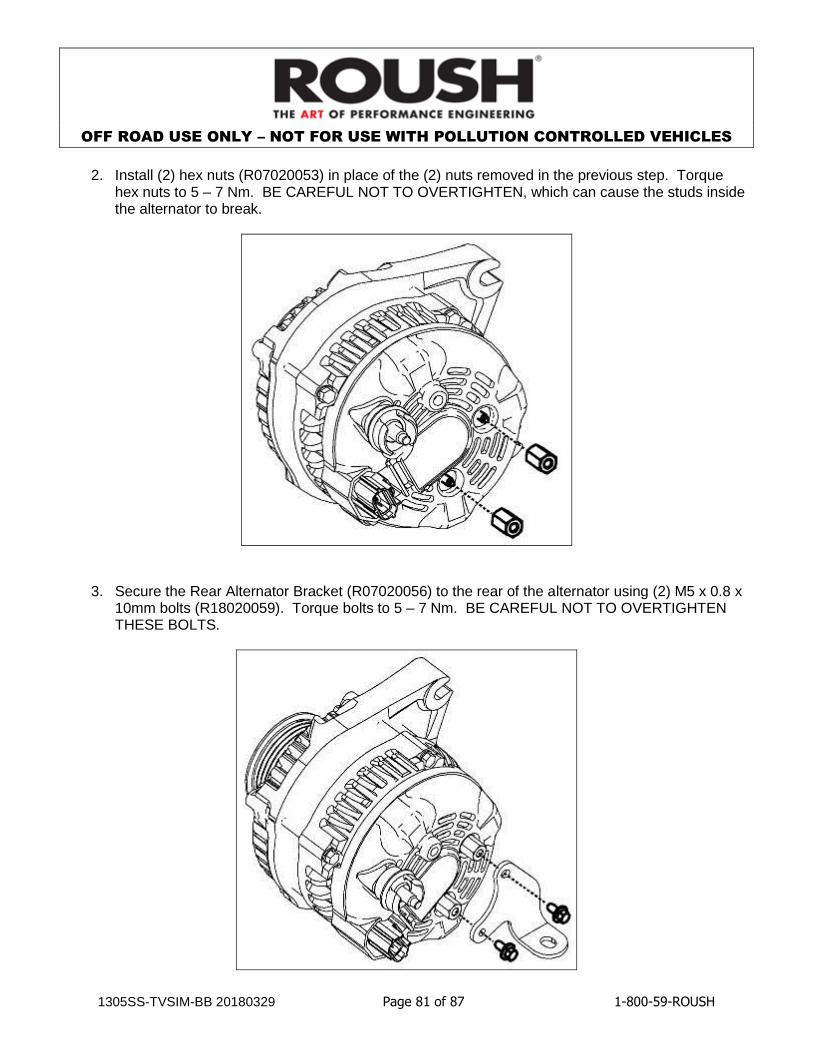
2. Install (2) hex nuts (R07020053) in place of the (2) nuts removed in the previous step. Torque
hex nuts to 5 – 7 Nm. BE CAREFUL NOT TO OVERTIGHTEN, which can cause the studs inside the alternator to break.
3. Secure the Rear Alternator Bracket (R07020056) to the rear of the alternator using (2) M5 x 0.8 x 10mm bolts (R18020059). Torque bolts to 5 – 7 Nm. BE CAREFUL NOT TO OVERTIGHTEN THESE BOLTS.

OFF ROAD USE ONLY – NOT FOR USE WITH POLLUTION CONTROLLED VEHICLES
1305SS-TVSIM-BB 20180329 Page 82 of 87 1-800-59-ROUSH
REVISIONS TO “SECTION D - INSTALLATION” (2009 Vehicles Only)
The following steps replace steps #1, #2, #11 - #15 and #18 - #20 of the Charge Harness and Wiring Installation in SECTION D- INSTALLATION section of the 05-08 instruction manual.
1. Push the Alternator Charge Harness (R07080034) retainers onto the driver side fuel rail studs as shown below.
2. Insert (2) M8 x 55mm Bolts (N808130) and (2) M8 Nuts (W520413) through the alternator bracket. Be sure to leave enough room to insert the alternator. Loosely secure the alternator charge harness eyelet to the alternator using the take off M8 nut. Slide the alternator onto the bolts and route the charge harness under the rear alternator bracket (refer to picture in step #3 on next page). Torque M8 bolts to 25 Nm (18 lb-ft).

OFF ROAD USE ONLY – NOT FOR USE WITH POLLUTION CONTROLLED VEHICLES
1305SS-TVSIM-BB 20180329 Page 83 of 87 1-800-59-ROUSH
3. Secure the alternator to the intake using (1) M8x25mm Bolt (W500224). Torque to 20 Nm. Torque the nut securing the charge harness to the alternator to 15 – 20 Nm. Plug in smart charge connector to alternator. Take special care to make sure the charge harness is not pinched anywhere.
4. Remove the (2) plastic fasteners that hold the cowl grill in place. Lift the cowl grill for easier access to replace the factory screw that secures the grounding strap to the cowl with (1) M6 x 1.0 x 18.5mm bolt (N605891) at the arrow shown. Torque bolt to 8 – 12Nm and replace plastic fasteners.
Route charge harness under the bracket in this area
Remove plastic fasteners
Insert new bolt here
W500224

OFF ROAD USE ONLY – NOT FOR USE WITH POLLUTION CONTROLLED VEHICLES
1305SS-TVSIM-BB 20180329 Page 84 of 87 1-800-59-ROUSH
5. Route the alternator charge harness through the grounding strap and secure it to the dash using (1) Stud Mount Zip Tie (R18080003). Push the Zip Tie onto the M6 Bolt from the previous step then wrap the zip tie around the cable.
6. Secure the alternator charge harness to the dash by pushing the retainer (Christmas tree) to the factory dash panel tab.

OFF ROAD USE ONLY – NOT FOR USE WITH POLLUTION CONTROLLED VEHICLES
1305SS-TVSIM-BB 20180329 Page 85 of 87 1-800-59-ROUSH
7. Run the remaining smart charge section of the charge harness with the battery harness that runs along passenger side strut tower and secure it using the zip ties that have been pre-installed on the charge harness. Route wires under the main wiring harness bundle and plug into the connector.
Route wires along here
Route wires under main bundle

OFF ROAD USE ONLY – NOT FOR USE WITH POLLUTION CONTROLLED VEHICLES
1305SS-TVSIM-BB 20180329 Page 86 of 87 1-800-59-ROUSH
Warranty All retail parts carry a 90-day warranty from the date of purchase. This warranty covers defects in materials or workmanship, and does not include (i) normal wear and tear, environmental conditions, improper installation; (ii) road hazards, misuse, abuse, neglect, accidents, collision, fire, theft, freezing, vandalism, riot, explosion, or objects striking the vehicle; (iii) misusing the vehicle, such as driving over curbs, overloading, racing, or using the vehicle as a stationary power source; (iv) altering, disassembling or modifying the parts; (v) defects caused or induced by failures, breakdowns, or damage by other parts, components or the vehicle; (vi) subjecting the parts to excessive moisture or water or any motor vehicle fluids (e.g.: oil, anti-freeze, battery acid, brake fluid, etc.); (vii) acts of God, natural disasters and other similar causes beyond the reasonable control of ROUSH; or (viii) application of chemicals that affect the parts. This Limited Warranty does not cover surface deterioration of paint, trim, and appearance items that result from use and/or exposure to the elements, such as stone chips, scratches, bird droppings, lightning, hail, windstorm, dings, dents, earthquake, road salt, tree sap, water or flood. ROUSH SHALL NOT BE LIABLE TO REIMBURSE CUSTOMER/DEALER FOR INCIDENTAL OR CONSEQUENTIAL DAMAGES RESULTING FROM THE INSTALLATION OR USE OF ANY PRODUCT SOLD THROUGH THIS CATALOG OR ARISING OUT OF ANY BREACH OF WARRANTY. EXCEPT AS MAY BE STATED IN THIS CATALOG, ROUSH DISCLAIMS ALL EXPRESS AND IMPLIED WARRANTIES, INCLUDING THE WARRANTIES OF MERCHANTABILITY AND FITNESS FOR A PARTICULAR PURPOSE. IN NO EVENT SHALL ROUSH’S LIABILITY EXCEED THE PRICE PAID BY CUSTOMER/DEALER FOR PRODUCTS SOLD REGARDLESS IF ROUSH HAS BEEN ADVISED IN ADVANCE OF ANY POTENTIAL PROBLEM OR IF A CLAIM IS BASED ON CONTRACT, TORT, STRICT LIABILITY, PRODUCT LIABILITY OR OTHERWISE. SOME STATES DO NOT ALLOW THE EXCLUSION OR LIMITATION OF IMPLIED WARRANTIES OR THEIR DURATION, OR LIABILITY FOR INCIDENTAL OR CONSEQUENTIAL DAMAGES, SO THE ABOVE EXCLUSIONS OR LIMITATIONS MAY NOT APPLY. This ROUSH Supercharger kit is designed and tested to function properly only on vehicles as they are equipped from the factory (completely stock powertrain). The use of aftermarket parts and equipment such as: cams, headers, nitrous oxide systems, other bolt-on performance parts, or any other performance parts not sold by, manufactured by, or approved of in writing by ROUSH, will result in powertrain and supercharger kit damage and will not be the responsibility of ROUSH in any way.

OFF ROAD USE ONLY – NOT FOR USE WITH POLLUTION CONTROLLED VEHICLES
1305SS-TVSIM-BB 20180329 Page 87 of 87 1-800-59-ROUSH
APPENDIX A
FORD RACING MUSTANG GT DUAL FUEL PUMP KIT
INSTRUCTION SHEET

M-9407-GT05 Mustang GT Dual Fuel Pump Kit INSTALLATION INSTRUCTIONS
NO PART OF THIS DOCUMENT MAY BE REPRODUCED WITHOUT PRIOR AGREEMENT AND WRITTEN PERMISSION OF FORD RACING PERFORMANCE PARTS.
Techline 1-800-367-3788 Page 1 of 15 IS-1850-0345
Factory Ford shop manuals are available from Helm Publications, 1-800-782-4356
Please visit www.fordracingparts.com for the most current instruction information
! ! ! PLEASE READ ALL OF THE FOLLOWING INSTRUCTIONS CAREFULLY PRIOR TO INSTALLATION. AT ANY TIME YOU DO NOT UNDERSTAND THE INSTRUCTIONS, PLEASE CALL THE FORD RACING
TECHLINE AT 1-800-367-3788 ! ! !
OVERVIEW: The following information describes the procedure for the installation of the M-9407-GT05 dual fuel pump kit into a 2005-07 Mustang GT. STEP 1: Release fuel system pressure.
1A: The fuel pump relay can be found in the bussed electrical center. The fuel pump relay is located in position 21 as shown in the inside cover of the bussed electrical center. Remove the fuel pump relay (see Fig. 1).
! ! ! WARNING: DO NOT SMOKE OR CARRY LIGHTED TOBACCO OR OPEN FLAME OF ANY TYPE WHEN WORKING ON OR NEAR ANY FUEL-RELATED COMPONENT. HIGHLY FLAMMABLE MIXTURES ARE
ALWAYS PRESENT AND MAY BE IGNITED, RESULTING IN POSSIBLE PERSONAL INJURY ! ! !
! ! ! WARNING: FUEL IN THE FUEL SYSTEM REMAINS UNDER HIGH PRESSURE EVEN WHEN THE ENGINE IS NOT RUNNING. BEFORE SERVICING OR DISCONNECTING ANY OF THE FUEL LINES OR FUEL SYSTEM
COMPONENTS, THE FUEL SYSTEM PRESSURE MUST BE RELIEVED TO PREVENT ACCIDENTAL SPRAYING OF FUEL, RESULTING IN PERSONAL INJURY OR A FIRE HAZARD ! ! !
! ! ! WARNING: DO NOT CARRY PERSONAL ELECTRONIC DEVICES SUCH AS CELL PHONES, PAGERS OR AUDIO EQUIPMENT OF ANY TYPE WHEN WORKING ON OR NEAR ANY FUEL-RELATED COMPONENTS. HIGHLY FLAMMABLE MIXTURES ARE ALWAYS PRESENT AND MAY BE IGNITED. FAILURE TO FOLLOW
THESE INSTRUCTIONS CAN RESULT IN PERSONAL INJURY ! ! !
! ! ! WARNING: THIS PROCEDURE INVOLVES FUEL HANDLING. BE PREPARED FOR SPILLAGE AT ALL TIMES AND ALWAYS OBSERVE FUEL HANDLING PRECAUTIONS. FAILURE TO FOLLOW THESE
INSTRUCTIONS CAN RESULT IN PERSONAL INJURY ! ! !
! ! ! WARNING: FUEL LEVEL MUST BE AT ¾ OF A TANK OR LOWER OR FUEL SPILLAGE WILL OCCUR WHEN FUEL MODULE IS REMOVED ! ! !
M-9407-GT05 Mustang GT Dual Fuel Pump Kit INSTALLATION INSTRUCTIONS
NO PART OF THIS DOCUMENT MAY BE REPRODUCED WITHOUT PRIOR AGREEMENT AND WRITTEN PERMISSION OF FORD RACING PERFORMANCE PARTS.
Techline 1-800-367-3788 Page 2 of 15 IS-1850-0345
Factory Ford shop manuals are available from Helm Publications, 1-800-782-4356
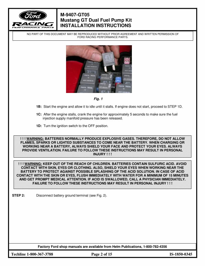
Fig. 1
1B: Start the engine and allow it to idle until it stalls. If engine does not start, proceed to STEP 1D.
1C: After the engine stalls, crank the engine for approximately 5 seconds to make sure the fuel injection supply manifold pressure has been released.
1D: Turn the ignition switch to the OFF position.
STEP 2: Disconnect battery ground terminal (see Fig. 2).
! ! ! WARNING: BATTERIES NORMALLY PRODUCE EXPLOSIVE GASES. THEREFORE, DO NOT ALLOW FLAMES, SPARKS OR LIGHTED SUBSTANCES TO COME NEAR THE BATTERY. WHEN CHARGING OR
WORKING NEAR A BATTERY, ALWAYS SHIELD YOUR FACE AND PROTECT YOUR EYES. ALWAYS PROVIDE VENTILATION. FAILURE TO FOLLOW THESE INSTRUCTIONS MAY RESULT IN PERSONAL
INJURY ! ! !
! ! ! WARNING: KEEP OUT OF THE REACH OF CHILDREN. BATTERIES CONTAIN SULFURIC ACID. AVOID CONTACT WITH SKIN, EYES OR CLOTHING. ALSO, SHIELD YOUR EYES WHEN WORKING NEAR THE BATTERY TO PROTECT AGAINST POSSIBLE SPLASHING OF THE ACID SOLUTION. IN CASE OF ACID
CONTACT WITH THE SKIN OR EYES, FLUSH IMMEDIATELY WITH WATER FOR A MINIMUM OF 15 MINUTES AND GET PROMPT MEDICAL ATTENTION. IF ACID IS SWALLOWED, CALL A PHYSICIAN IMMEDIATELY.
FAILURE TO FOLLOW THESE INSTRUCTIONS MAY RESULT IN PERSONAL INJURY ! ! !

M-9407-GT05 Mustang GT Dual Fuel Pump Kit INSTALLATION INSTRUCTIONS
NO PART OF THIS DOCUMENT MAY BE REPRODUCED WITHOUT PRIOR AGREEMENT AND WRITTEN PERMISSION OF FORD RACING PERFORMANCE PARTS.
Techline 1-800-367-3788 Page 3 of 15 IS-1850-0345
Factory Ford shop manuals are available from Helm Publications, 1-800-782-4356
Fig. 2 STEP 3: The fuel level in the tank should be ¾ of a tank or less before proceeding. If fuel exceeds more than
¾ of a tank, then follow STEPS 4-6. If fuel level is ¾ of a tank or less, then proceed to STEP 7. STEP 4: Remove the fuel tank filler cap. STEP 5: Insert a suitable drain hose into the fuel tank filler pipe until it reaches the fuel tank inlet tube.
CAUTION! The fuel pump and fuel level sensor will be below the fuel level in the tank when the tank is full. Make sure to drain ¼ of the fuel capacity through the filler pipe prior to removing the pumps or fuel spillage will occur.
STEP 6: Attach the fuel storage tanker to the fuel drain hose and remove as much fuel as possible from the
fuel tank filler pipe. The fuel tank has a 16-gallon capacity. The removal of 4 gallons would lower the fuel level ¼ of a tank.
STEP 7: Remove the rear seat bottom and any insulation padding covering the fuel pump access cover.
7A: From under the front of the rear cushion assembly, push in the seat cushion release tab located on the left and right of the seat, lift and remove the rear cushion assembly (see Fig. 3).

M-9407-GT05 Mustang GT Dual Fuel Pump Kit INSTALLATION INSTRUCTIONS
NO PART OF THIS DOCUMENT MAY BE REPRODUCED WITHOUT PRIOR AGREEMENT AND WRITTEN PERMISSION OF FORD RACING PERFORMANCE PARTS.
Techline 1-800-367-3788 Page 4 of 15 IS-1850-0345
Factory Ford shop manuals are available from Helm Publications, 1-800-782-4356
Fig. 3
STEP 8: Remove the fuel pump access cover (see Fig. 4).
Fig. 4 STEP 9: Disconnect the fuel pump electrical connector (see Fig. 5).

M-9407-GT05 Mustang GT Dual Fuel Pump Kit INSTALLATION INSTRUCTIONS
NO PART OF THIS DOCUMENT MAY BE REPRODUCED WITHOUT PRIOR AGREEMENT AND WRITTEN PERMISSION OF FORD RACING PERFORMANCE PARTS.
Techline 1-800-367-3788 Page 5 of 15 IS-1850-0345
Factory Ford shop manuals are available from Helm Publications, 1-800-782-4356
Fig. 5
CAUTION! If the liquid or vapor tube is damaged (torn, holes or delaminated), the effected tube assembly must be replaced with a new tube assembly. Do not use aftermarket sleeving. Do not re-adhere loose sleeving material.
CAUTION! When reusing liquid or vapor tube connectors, make sure to use compressed air to remove any foreign material from the connector retaining clip area before separating from the tube. Apply clean engine oil to the end of the tube before inserting the tube into the connector.
CAUTION! Fuel injection equipment is manufactured to very precise tolerances and fine clearances. It is therefore essential that absolute cleanliness be observed when working with these components. Always install blanking plugs to any open orifices or tubes.
STEP 10: Disconnect the fuel tube quick connect coupling on the fuel pump.
10A: Press the fuel tube quick connect coupling button and pull the fuel tube to disconnect (see Fig. 6).
Fig. 6

M-9407-GT05 Mustang GT Dual Fuel Pump Kit INSTALLATION INSTRUCTIONS
NO PART OF THIS DOCUMENT MAY BE REPRODUCED WITHOUT PRIOR AGREEMENT AND WRITTEN PERMISSION OF FORD RACING PERFORMANCE PARTS.
Techline 1-800-367-3788 Page 6 of 15 IS-1850-0345
Factory Ford shop manuals are available from Helm Publications, 1-800-782-4356
STEP 11: Using a fuel tank lock ring wrench or a brass punch, remove the fuel pump retaining lock ring
(see Figs. 7-8).
Fig. 7 Fig. 8
CAUTION! The fuel pump must be handled carefully to avoid damage to the float arm, filter and convolute hoses.
STEP 12: Carefully lift the fuel pump out of the fuel tank enough to access and release the fuel cross-over tube
quick connect coupling from the fuel pump (see Fig. 9).
Fig. 9 STEP 13: Completely remove the fuel pump from the fuel tank (see Fig. 10).

M-9407-GT05 Mustang GT Dual Fuel Pump Kit INSTALLATION INSTRUCTIONS
NO PART OF THIS DOCUMENT MAY BE REPRODUCED WITHOUT PRIOR AGREEMENT AND WRITTEN PERMISSION OF FORD RACING PERFORMANCE PARTS.
Techline 1-800-367-3788 Page 7 of 15 IS-1850-0345
Factory Ford shop manuals are available from Helm Publications, 1-800-782-4356
Fig. 10
CAUTION! Inspect the surfaces of the fuel pump mounting flange and fuel tank O-ring seal contact surfaces. Do not polish or adjust the O-ring seal contact area of the fuel tank flange or the fuel tank. Install a new fuel tank if the O-ring seal contact area is bent, scratched or corroded.
CAUTION! Make sure to install a new fuel pump O-ring seal and lock ring.
STEP 14: To install, apply clean engine oil to the O-ring seal. STEP 15: Install new fuel pump O-ring seal (see Fig. 11).
Fig. 11 STEP 16: Position the dual fuel pump into the fuel tank.

M-9407-GT05 Mustang GT Dual Fuel Pump Kit INSTALLATION INSTRUCTIONS
NO PART OF THIS DOCUMENT MAY BE REPRODUCED WITHOUT PRIOR AGREEMENT AND WRITTEN PERMISSION OF FORD RACING PERFORMANCE PARTS.
Techline 1-800-367-3788 Page 8 of 15 IS-1850-0345
Factory Ford shop manuals are available from Helm Publications, 1-800-782-4356
STEP 17: Connect the cross-over fuel tube quick connect coupling to the fuel pump.
CAUTION! Make sure the fuel tube clicks into place when installing the tube. To make sure that the fuel tube is fully seated, pull on the tube.
STEP 18: Make sure the alignment arrows on the dual fuel pump and the fuel tank meet before tightening the dual
fuel pump lock ring. Using the special tool or brass punch, install the dual fuel pump with the new lock ring.
18A: Tighten the lock ring until it meets the stops on the fuel tank.
NOTE: The fuel pump is spring-loaded into the tank and may require slight pressure to install lock ring.
STEP 19: Connect the quick connect coupling on top of the dual fuel pump.
CAUTION! Make sure the fuel tube clicks into place when installing the tube. To make sure that the fuel tube is fully seated, pull on the tube.
STEP 20: Remove black cover from inside trunk to access fuel pump driver module (see Fig. 12).
Fig. 12
STEP 21: Disconnect fuel pump driver module located in spare tire well on driver side (see Fig. 13).

M-9407-GT05 Mustang GT Dual Fuel Pump Kit INSTALLATION INSTRUCTIONS
NO PART OF THIS DOCUMENT MAY BE REPRODUCED WITHOUT PRIOR AGREEMENT AND WRITTEN PERMISSION OF FORD RACING PERFORMANCE PARTS.
Techline 1-800-367-3788 Page 9 of 15 IS-1850-0345
Factory Ford shop manuals are available from Helm Publications, 1-800-782-4356
Fig. 13
STEP 22: Mount additional fuel pump driver module in spare tire well on opposite side of existing fuel pump driver (see Fig. 14).
Fig. 14 STEP 23: Mount RELAY from harness on inside of tire well to the left of the stock fuel pump driver module
(see Fig. 15).

M-9407-GT05 Mustang GT Dual Fuel Pump Kit INSTALLATION INSTRUCTIONS
NO PART OF THIS DOCUMENT MAY BE REPRODUCED WITHOUT PRIOR AGREEMENT AND WRITTEN PERMISSION OF FORD RACING PERFORMANCE PARTS.
Techline 1-800-367-3788 Page 10 of 15 IS-1850-0345
Factory Ford shop manuals are available from Helm Publications, 1-800-782-4356
Fig. 15 STEP 24: Connect connector labeled FPDM BODY SIDE CONNECTOR into the harness where the existing fuel
pump driver module was connected. STEP 25: Connect connector labeled FPDM NO. 1 to stock fuel pump driver module. STEP 26: Mount wires labeled RELAY GROUND and FPDM NO. 1 GROUND in hole next to stock ground using
ground screw (see Fig. 16).
Fig. 16 STEP 27: Connect connector labeled FPDM NO. 2 to newly mounted fuel pump driver module on passenger side. STEP 28: Mount wire labeled FPDM NO. 2 GROUND to stock ground for audio amp on passenger side
(see Fig. 17).

M-9407-GT05 Mustang GT Dual Fuel Pump Kit INSTALLATION INSTRUCTIONS
NO PART OF THIS DOCUMENT MAY BE REPRODUCED WITHOUT PRIOR AGREEMENT AND WRITTEN PERMISSION OF FORD RACING PERFORMANCE PARTS.
Techline 1-800-367-3788 Page 11 of 15 IS-1850-0345
Factory Ford shop manuals are available from Helm Publications, 1-800-782-4356
Fig. 17 STEP 29: Run connectors labeled DUAL PUMP CONNECTOR and SENDER CONNECTOR along the wall of the
driver side of trunk, under rear seat and into rear seat area where the dual pump is located.
29A: For 2005 Mustang GT, a 1½” diameter hole will need to be cut out in the center of the access cover for the fuel pump (see Fig. 18). Once hole is cut out, pull DUAL PUMP CONNECTOR and SENDER CONNECTOR (1) through hole and seal hole with grommet. Unlock existing 4-pin female connector on the harness previously connected into the stock fuel pump. Unlock the connector by pulling the blue center piece forward (see Fig. 19). Proceed to STEP 29C.
Fig. 18 Fig. 19

M-9407-GT05 Mustang GT Dual Fuel Pump Kit INSTALLATION INSTRUCTIONS
NO PART OF THIS DOCUMENT MAY BE REPRODUCED WITHOUT PRIOR AGREEMENT AND WRITTEN PERMISSION OF FORD RACING PERFORMANCE PARTS.
Techline 1-800-367-3788 Page 12 of 15 IS-1850-0345
Factory Ford shop manuals are available from Helm Publications, 1-800-782-4356
29B: For 2006 Mustang GT and beyond, a second hole with a 1½” diameter will need to be cut into the access cover. The hole should be ½” away from existing hole to allow clearance for the new grommet to seal. Once the hole is cut out, pull DUAL PUMP CONNECTOR and SENDER CONNECTOR (1) through hole and seal hole with grommet. Do not take the existing harness out of the existing hole in the access cover. Unlock the existing 4-pin female connector (connector on the end of the existing harness going through access cover) previously connected into the stock fuel pump. Unlock the connector by pulling the blue center piece forward (see fig. 19).
29C: Release terminals for the LB/YE wire and the LG/VT wire from the connector housing. Do not remove terminal from wire. These are the fuel sender wires.
STEP 30: Insert fuel sender wires into the connector labeled SENDER CONNECTOR (2) with the LB/YE wire going
into the left side and the LG/VT wire going into the right (see Fig. 20).
Fig. 20
STEP 31: Connect SENDER CONNECTOR (1) into SENDER CONNECTOR (2). Once connection is made, the
LG/VT wire should line up with the RD/YE wire and the LB/YE with the BK wire. STEP 32: Connect the DUAL PUMP CONNECTOR to the newly installed dual pump. STEP 33: Install access cover (see Fig. 21 – 2005 Mustang GT view).

M-9407-GT05 Mustang GT Dual Fuel Pump Kit INSTALLATION INSTRUCTIONS
NO PART OF THIS DOCUMENT MAY BE REPRODUCED WITHOUT PRIOR AGREEMENT AND WRITTEN PERMISSION OF FORD RACING PERFORMANCE PARTS.
Techline 1-800-367-3788 Page 13 of 15 IS-1850-0345
Factory Ford shop manuals are available from Helm Publications, 1-800-782-4356
Fig. 21 STEP 34: Run wire labeled FUSE/POWER (1) along the trunk wall, into the back seat of the passenger side, and
along the wire track on the passenger side of the vehicle (see Figs. 22-24).
Fig. 22 Fig. 23
Fig. 24

M-9407-GT05 Mustang GT Dual Fuel Pump Kit INSTALLATION INSTRUCTIONS
NO PART OF THIS DOCUMENT MAY BE REPRODUCED WITHOUT PRIOR AGREEMENT AND WRITTEN PERMISSION OF FORD RACING PERFORMANCE PARTS.
Techline 1-800-367-3788 Page 14 of 15 IS-1850-0345
Factory Ford shop manuals are available from Helm Publications, 1-800-782-4356
34A: A hole will need to be placed in the grommet located in the lower area of the front wall on the passenger side in order to run the wire through (see Fig. 25).
Fig. 25 STEP 35: Lift vehicle and remove the right front tire from vehicle along with the rear fender well cover. Continue to
run wire along existing wire harness in fender well using wire ties to secure the wire along the existing wire harness (see Fig. 26).
Fig. 26 STEP 36: Remove innermost fastener on front fender well cover and continue to run wire into engine compartment.
The wire should come through the hole located near the washer fluid neck (see Figs. 27-28).

M-9407-GT05 Mustang GT Dual Fuel Pump Kit INSTALLATION INSTRUCTIONS
NO PART OF THIS DOCUMENT MAY BE REPRODUCED WITHOUT PRIOR AGREEMENT AND WRITTEN PERMISSION OF FORD RACING PERFORMANCE PARTS.
Techline 1-800-367-3788 Page 15 of 15 IS-1850-0345
Factory Ford shop manuals are available from Helm Publications, 1-800-782-4356
Fig. 27 Fig. 28 STEP 37: Connect FUSE/POWER (1) to FUSE/POWER (2).
STEP 38: Connect POWER to hot side of bussed electrical center (see Fig. 29).
Fig. 29 STEP 39: Reinstall relay in position 21 of bussed electrical center.
STEP 40: Connect negative terminal of battery.
STEP 41: Check for leaks before starting the engine. NOTE: It may take more than one key cycle to pressurize the fuel system. Cycle the ignition key and wait
3 seconds to pressurize the fuel system.
STEP 42: Start the engine and check for leaks.