not all information has been verified or corroborated ... internal_investigation... · (from...
TRANSCRIPT
DRAFT – WORK IN PROGRESS – SUBJECT TO ADDITIONAL INVESTIGATION AND REVISION
Deepwater Horizon Incident – Internal Investigation
1
Not all Information has been verified or corroborated. Subject to review based on additional information or analysis.

DRAFT – WORK IN PROGRESS – SUBJECT TO ADDITIONAL INVESTIGATION AND REVISION
Areas of Discussion
• Investigation Overview
• Focus AreasPrimary Well Control
Well integrityProcedures
Secondary Well ControlBlowout preventer
Ignition SourceEvacuation & Response
• Forward Plan
2

DRAFT – WORK IN PROGRESS – SUBJECT TO ADDITIONAL INVESTIGATION AND REVISION
Investigation Overview
• RemitThe purposes of this investigation are (1) to establish the root cause(s) of events that led to the incident onboard the Deepwater Horizon on the night of Tuesday, April 20, 2010 and (2) to review the personnel evacuation, the rig layout that allowed for an evacuation, and the emergency response.
• Key Questions to Address During the Investigation1) Why was primary well control lost? See slides 6-12
Well designCasing, cement, well head hanger seal assembly
2) Why was secondary well control unable to stop the flow of well fluids? See slides 13-15
3) How did the well bore fluids ignite? See slide 16
4) Should the rig structural design be improved for personnel protection? See slide 17
5) Can evacuation and emergency response protocols be improved? See slide 17
3
DRAFT – WORK IN PROGRESS – SUBJECT TO ADDITIONAL INVESTIGATION AND REVISION
Investigation Overview
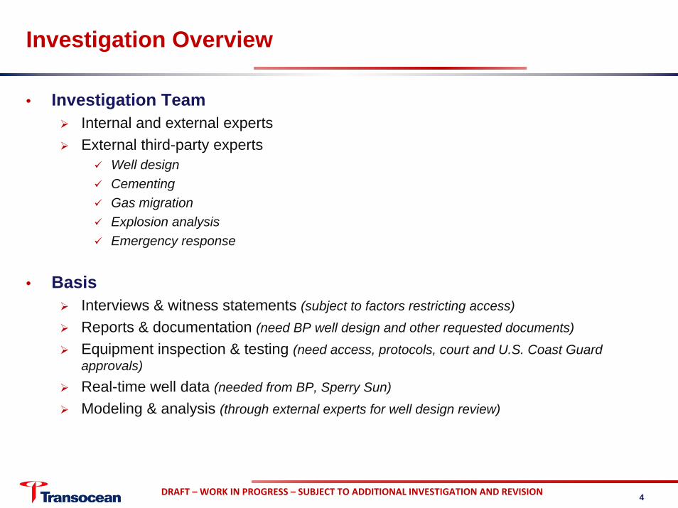
• Investigation Team Internal and external expertsExternal third-party experts
Well designCementingGas migrationExplosion analysisEmergency response
• BasisInterviews & witness statements (subject to factors restricting access)Reports & documentation (need BP well design and other requested documents)
Equipment inspection & testing (need access, protocols, court and U.S. Coast Guard approvals)Real-time well data (needed from BP, Sperry Sun)
Modeling & analysis (through external experts for well design review)
4
DRAFT – WORK IN PROGRESS – SUBJECT TO ADDITIONAL INVESTIGATION AND REVISION
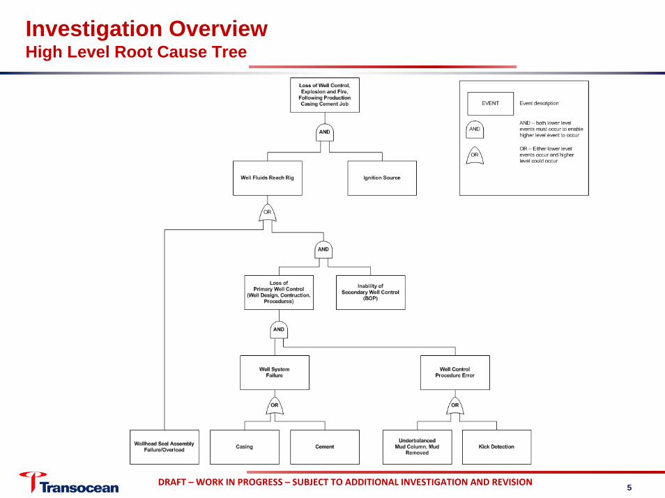
Investigation OverviewHigh Level Root Cause Tree
5
DRAFT – WORK IN PROGRESS – SUBJECT TO ADDITIONAL INVESTIGATION AND REVISION
Loss of Primary Well ControlCement – Areas of Investigation
• DesignWas it appropriate to utilize nitrogen foamed cement at this depth?
May be uncommon at this depthTypically used for shallow conductor casing string
Did the operator give the cement enough time to cure? (from Halliburton lab test reports)
Test on 3/29 of 9-7/8” liner slurry (previous casing): 15 hours needed to reach 2100 psi compressive strength
Test on 4/12 of 7” casing slurry : 0 psi compressive strength after 24 hours; needed 48 hours to reach compressive strength of 1590 psi
– Negative test started ~18 hours after pumped– Do not have any sample test results from rig samples; requested
Was the volume for 7” production casing cement job appropriate?60 bbls pumped (requested third party caliper logs to determine if adequate)
16.7 ppg cement in shoe track over 14 ppg mud in open hole beneath the 7” shoe– could fall out into the open hole
Estimate of 2 bbls nitrogen cement in shoe track – normally would pump all into annulus
6

DRAFT – WORK IN PROGRESS – SUBJECT TO ADDITIONAL INVESTIGATION AND REVISION
Loss of Primary Well ControlCement – Areas of Investigation
• Was there contamination of the cement?Wiper plug was run through two casing internal diameters
Potential for mud bypassing plug into cementCirculated bottoms up only to the wellhead rather than to the surface
Potential cuttings in well borePotential non-homogeneous mud or gas content
– Could lead to cement channeling and flow path for formation fluids
• Was there a problem with the float equipment?There were 9 attempts to activate (IADC and BP daily report 4/19)
Double flapper typeRequires back pressure from annulus side to closeLess than 40 psi back pressure from annulus by calculation
– Potential to open while cement is setting
1st positive test on casing against wiper plug at 10 hours set time – potential to slightly open flappers during cure time
• Were the appropriate tests run following the cement job?No cement bond log was run prior to proceeding with pressure testsNeed to test samples of cement recovered by BP from the Damon Bankston deck
7
DRAFT – WORK IN PROGRESS – SUBJECT TO ADDITIONAL INVESTIGATION AND REVISION
Loss of Primary Well ControlCasing Hanger Seal Assembly – Areas of Investigation
• Were Operator procedures appropriate?Operator did not run lock down sleeve prior to negative test or displacement
No bottoms up circulation prior to landing of 7” casing hangerPotential to allow debris in seal area
• Was the hanger design adequate?Was outer lock ring run on assembly?
Need to understand rating or tolerance for pressure on annulus side
Annulus side pressureCould pressures measured (Sperry Sun data) unseat seal assembly?Pressures seen at well head had potential to make 9-7/8” X 7” casing string neutral weight
Need Dril-quip hanger running report showing hanger arrangement as it was run, including 9-7/8” seal assembly
8
DRAFT – WORK IN PROGRESS – SUBJECT TO ADDITIONAL INVESTIGATION AND REVISION
Loss of Primary Well ControlProcedures – Negative Test
• Negative pressure testingSet up for negative pressure test began approximately 17:00
~17:15, 60 barrels of spacer moved below annularIncreased annular activating pressure from 1200 to 1900 psiSet up fluids through crew handover at 18:00
Under-displaced 16 ppg spacerSpacer was not in MMS permitPosition under annular led to confusing pressure readingsFloat equipment under tested by 285 psi
Discussion 18:00-19:00 About fluid volumes due to movement below annular and line up for monitoring – either from drill pipe (normal procedure used by rig) or kill line (MMS permit)Either line up is appropriate and will correctly monitor well
• Area of InvestigationTypically negative test to ~500 ft below well head with sea water
~3300 ft below – stated on MMS permit in order to prevent well head seal area contaminationImposed additional 1000 psi differential on float equipment/casing/cement
Where did ~60 bbls from riser go below annularU-tube up kill line or up drill pipe?Impacts final negative test pressure applied to well
9
Not all Information has been verified or corroborated. Subject to review based on additional information or analysis.

DRAFT – WORK IN PROGRESS – SUBJECT TO ADDITIONAL INVESTIGATION AND REVISION
Loss of Primary Well ControlProcedures – Negative Test Setups
10
Not all Information has been verified or corroborated. Subject to review based on additional information or analysis.
Boost LineKill
Choke
KillWellhead @ 5054'
36"
28"
22"
18"
16" 14 ppg
13-5/8"
11-7/8"
9-7/8"
7" x 9-7/8"
TIH to +500' BML
2.
Negative Test Standard Procedure
unit
Negative Test:
SBM 14.0 ppg
Seawater 8.5 ppg
5. Monitor well
DP
3.
Open low torque valve to cement4.
1.
Displace spacer above annular
Spacer 16.0 ppg
Close annular and IBOP
Boost LineKill
Choke
Kill OpenWellhead @ 5054'
36"
28"
22"
18"
16" 14 ppg
13-5/8"
11-7/8"
9-7/8"
7" x 9-7/8"
2. Displace seawater to wellhead
3. Close annular
4. Displace kill line with seawater
5. Monitor well on kill line
SBM 14.0 ppg
Seawater 8.5 ppg
Negative Test:1. TIH to 8367' (+3,300' BML)
Negative Test Approved on MMS Permit
DP Boost LineKill
Choke
Kill OpenWellhead @ 5054'
36"
28"
22"
18"
16" 14 ppg
13-5/8"
11-7/8"
9-7/8"
7" x 9-7/8"
3.
TIH to 8367' (+3,300' BML)
Underdisplaced spacer
Closed annular
Negative Test Setup at 4/20 17:45
Negative Test:1.
2.
Spacer 16.0 ppg
SBM 14.0 ppg
Seawater 8.5 ppg
DP

DRAFT – WORK IN PROGRESS – SUBJECT TO ADDITIONAL INVESTIGATION AND REVISION
Loss of Primary Well ControlReview of Procedures
• Circulate out riser 20:00 to 21:08Mud circulation out prior to second plug – well reaches highest underbalanced pressure to this point
Shut down for static sheen test to begin going over board with water-based spacer
• Areas of InvestigationFlow changes and volumes
Mud transfers
Flow sensors accuracyRequire Sperry Sun system set up details and calibration records
11
Not all Information has been verified or corroborated. Subject to review based on additional information or analysis.
Boost LineKill
Choke
Boost line open
Wellhead @ 5054'
36"
28"
22"
18"
16" 14 ppg
13-5/8"
11-7/8"
9-7/8"
7" x 9-7/8"
SBM 14.0 ppg
Seawater 8.5 ppg
DP
Riser Displacement4/20 21:08 Static Sheen Test
Spacer 16.0 ppg

DRAFT – WORK IN PROGRESS – SUBJECT TO ADDITIONAL INVESTIGATION AND REVISION
Loss of Primary Well ControlReview of Procedures (continued)
• Flow Show at 20:58Trip tank being discharged to pits through flow line (normal procedures ahead of change from oil to water mud in active system)
At same point pumps ramp down for stop at static sheen test
Increased flow out due to discharge of trip tank
Driller expected to see flow increaseFlow returned near pre-tank discharge level when trip tank pump stopped, THEN increasedPotentially masked the gain
• Area of Investigation Complete review of all volumes and real time data (received 5/24)
Use of trip tank in operation
Sperry Sun sensors failure to record a flow out after 21:10
21:08 Start of Static Sheen Test; Shut down pumps
20:58 Start dumping of Trip Tank to flow line; Driller expects to see flow increase(Gain 15.4 bbls)
Source: BP OCS-G 32306 001 ST00BP01 Mississippi Canyon 252 Macondo, Last 2 hours before end of transmission
Not all Information has been verified or corroborated. Subject to review based on additional information or analysis.
12
DRAFT – WORK IN PROGRESS – SUBJECT TO ADDITIONAL INVESTIGATION AND REVISION
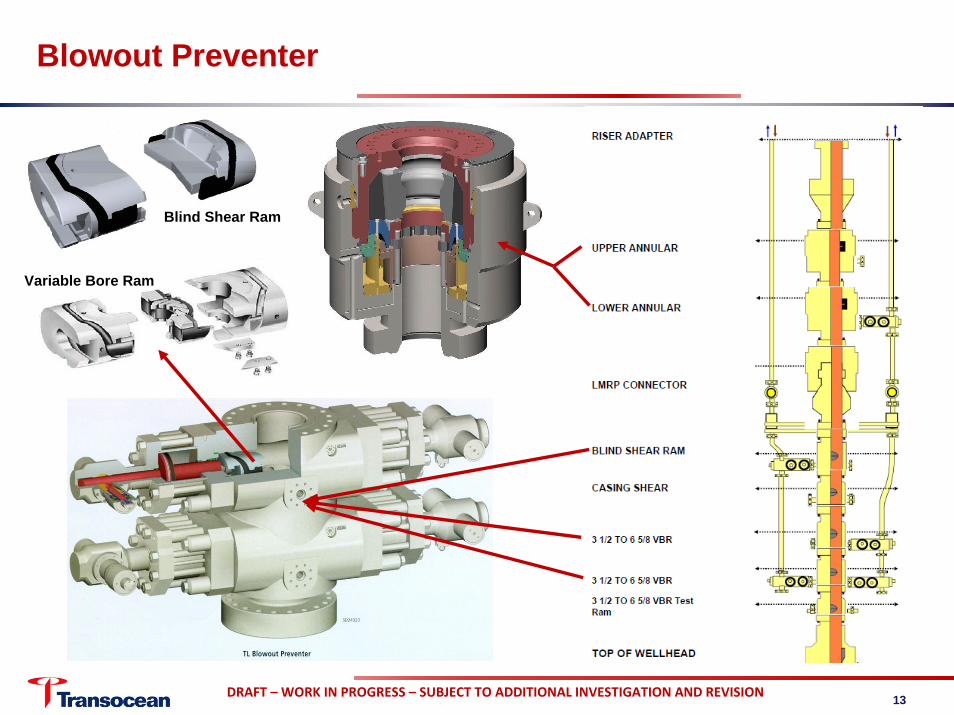
Blowout Preventer
Blind Shear Ram
Variable Bore Ram
13

DRAFT – WORK IN PROGRESS – SUBJECT TO ADDITIONAL INVESTIGATION AND REVISION
Blowout PreventerTesting
• Function TestPreventers activated individually from surface to confirm commands perform subseaNo pressure appliedRequired every 7 days
• Pressure TestPreventers activated individually from surface Pressure applied individually to maximum anticipated well bore pressure (per Operator or MMS)
Required every 14 days • Timeline of tests from start of drilling – all tests passed (source: IADC reports)
14

DRAFT – WORK IN PROGRESS – SUBJECT TO ADDITIONAL INVESTIGATION AND REVISION
Blowout PreventerEvents & History
• Stripping Operation – 6 AprilWitness stated pieces of rubber returned in mud flow over shakers Estimated to be from stripping operations during well control event (~1300 ft pipe stripped)Expected normal wear on lower annular rubber elementAnnular passed subsequent pressure test on 10 April (250psi/3500psi)
• Condition at the time of incidentLower annular & diverter closed prior to explosion (witness statements)
Visual indications on Toolpusher panelFluid seen coming from diverter line by rig & boat crew (diverter confirmation)Flow subsided and then started again (annular confirmation)Last pressure reading over 5400 psi and exceeds lower annular rating of 5000 psi
Evidence of upper pipe ram activation Potential for multiple tubulars in BOP at time of incident
• Action items/work neededFull control system software review
Software code requested from manufacturer for investigation
Review of data from ROV interventionAssemble 10-yr history of BOP maintenance, modifications, & upgrades
15
Annular closed on drill pipe
Source: Cameron web site

DRAFT – WORK IN PROGRESS – SUBJECT TO ADDITIONAL INVESTIGATION AND REVISION
Ignition of Well Fluids
• From witness statementsGas cloud like fog from water up to main deck (observer on Bankston supply boat)
Fishing boat motoring from under aft lifeboat station (roustabout)Gas/well fluids exiting diverter lines, derrick, and degasser overflow lineGas “hiss” like bleeding off pressure (potential release from slip joint packer to moon pool)
• Potential ignition sourcesFishing boat Supply boatEnginesEX-equipment in derrick and moon pool
• Area of investigationGas dispersion study in prevailing weather conditions (little or no wind)
Incorporate rig ventilation systemProximity of boats
Structural damage assessment with review of bulkhead strength against design
16
DRAFT – WORK IN PROGRESS – SUBJECT TO ADDITIONAL INVESTIGATION AND REVISION
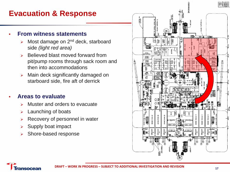
Evacuation & Response
• From witness statementsMost damage on 2nd deck, starboard side (light red area)Believed blast moved forward from pit/pump rooms through sack room and then into accommodationsMain deck significantly damaged on starboard side, fire aft of derrick
• Areas to evaluateMuster and orders to evacuateLaunching of boatsRecovery of personnel in waterSupply boat impactShore-based response
17
DRAFT – WORK IN PROGRESS – SUBJECT TO ADDITIONAL INVESTIGATION AND REVISION
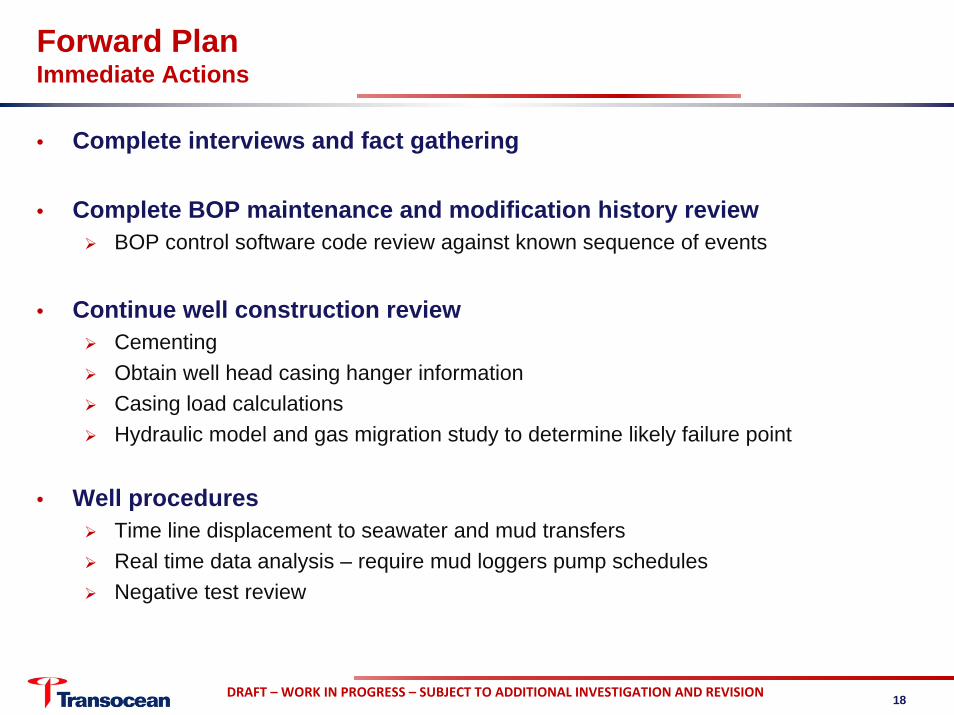
Forward PlanImmediate Actions
• Complete interviews and fact gathering
• Complete BOP maintenance and modification history reviewBOP control software code review against known sequence of events
• Continue well construction reviewCementingObtain well head casing hanger informationCasing load calculationsHydraulic model and gas migration study to determine likely failure point
• Well procedures Time line displacement to seawater and mud transfersReal time data analysis – require mud loggers pump schedulesNegative test review
18