norwood director meters - doug.kerrdougkerr.net/pumpkin/articles/norwood_director_meters.pdf ·...
TRANSCRIPT

Copyright © 2014 Douglas A. Kerr. May be reproduced and/or distributed but only intact, including this notice. Brief excerpts may be reproduced with credit.
The "Norwood Director" family of photographic exposure meters
Douglas A. Kerr
Issue 5 December 7, 2014
ABSTRACT AND INTRODUCTION
An important family of photographic exposure meters consists of meters which in the earlier days of the family had the name "Norwood Director". The family has a fascinating history with respect to the meters themselves and with respect to the various people and firms involved. In this article I try to paint the overall picture of this family and its story, and describe most of the meters in it. Basic background on the underlying technical theory of incident light exposure metering and related issues, and some specialized data, are given in appendixes.
1. GENERAL
1.1 Background
Appendix A gives some background in Photographic Exposure Metering.
1.2 Incremental descriptions
When a certain feature is introduced at a particular model of the line, it will be discussed there. If there is no mention of this feature in the description of a following model, we may in general assume that it is still in play there.
1.3 Our personal collection
We have specimens of several of the meter models discussed here in our personal collection. These are indicated by a "smiley face" next to the main photograph of the model. Unless indicated otherwise, the photographs of these are by the author.
1.4 Other photo credits
Several photos in this article are copyright James Ollinger or John D. de Vries, and are used by permission. Thanks, guys.
1.5 The unit of illuminance
Most of the meters discussed here have a basic meter scale calibrated in the non-SI (US customary) unit of illuminance which is variously written as “footcandle”, “foot-candle”, or “foot candle”. There is no applicable standard that makes one of those forms “correct”. The forms “foot-candle” and “foot candle” are deprecated as they suggest

The "Norwood Director" family Page 2
that the unit is the product of the unit “foot” and the unit “candle”, which it is not. Thus we uniformly use the form “footcandle” when discussing the unit itself.
On the other hand, the unit name is presented on the face of the meters as “foot candles”, “foot-candles”, or (in the latest model only) “ft-cd”. I will use those forms only when discussing the specific markings on a meter.
1.6 The light measurement system
All the meters described in this article use a photovoltaic photocell, which generates an electrical voltage when exposed to light. Its output is directly read by a microammeter. No battery is involved.
2. THE NAISSANCE OF THE "NORWOOD CONCEPT"
In the mid 1930's, incident light exposure metering in the common situation of the lighting of a human subject with two light sources (under the key-fill technique) required at the least taking two measurements with an incident light exposure meter, combining them mathematically, and then feeding the composite result into the meter's exposure calculator to develop the photographic exposure recommendation.
Donald W. Norwood had the vision that a reflected light exposure meter in which the receptor was a hemisphere, rather than a flat plate as in most meters of that type, would be able, in a single measurement, to develop an optimal recommendation of photographic exposure over a range of subject and lighting situations.
Subjective tests under controlled conditions tests, as well as a period of practical use of prototype meters of this configuration, seem to have confirmed Norwood's intuition. Appendix C discusses these tests and their implications.
Although the original concept was of an actual hemispherical receptor, Norwood later realized that a translucent hemispherical "light-receiving member", mounted over a flat receptor, would produce essentially the same behavior and be much less costly to manufacture.
Norwood was granted a patent in 1940 on this scheme.
3. PHOTO RESEARCH CORPORATION
3.1 Founding
Norwood's colleague cinematographer Karl Freund, likely at Norwood's urging, founded Photo Research Corporation in 1941, and began the

The "Norwood Director" family Page 3
design of an exposure meter to exploit Norwood's concept, presumably under license under the Norwood patent.
Figure 1. Karl Freund (center) in 1941
Image: International Encyclopedia of Cinematographers
Figure 1 shows Freund in 1941 (with Risë Stevens and Nelson Eddy, on the set of "The Chocolate Soldier") using what must have been an early prototype of this new meter (cf. figure 2).
3.2 The Norwood Director exposure meter, "Model A"
The new meter came into general production in 1946 under the name "Norwood Director" (This name was likely adopted at the 11th hour; the Bakelite housing of the meter had molded in just "Norwood Exposure Meter"). This model is today referred to by exposure meter historians as the Norwood Director, “Model A”. We see it in Figure 2.
Figure 2. Norwood Director exposure meter ("Model A")

The "Norwood Director" family Page 4
This design was made for many years, but only under the name "Norwood Director" for about a year, owing to other developments.
4. THE “BROCKWAY FIRM” ERA
4.1 American Bolex
In 1947, American Bolex (owned by the Brockway family), at the time the US distributor of the Paillard-Bolex motion picture cameras, apparently acquired the exclusive rights to the trademark "Norwood Director", and apparently as well non-exclusive rights under Norwood's patent covering the meter's unique operating principle.
We can only conjecture how this came to happen. Perhaps Don Norwood felt that Photo Research was not sufficiently aggressive in marketing Norwood's patented design concept and sought a second channel of exploitation. And perhaps Ezra Brockway, the head of American Bolex, foresaw that he would soon lose his Paillard-Bolex franchise and that the firm would need a new product line.
4.2 Norwood Director Model B
4.2.1 Introduction
American Bolex, through the work of industrial designer Alpheus Maple, gave the meter a wholly new (and more stylish) physical design, and, beginning in 1948, that firm marketed the new design under the "Norwood Director" name. This model was called the Model B (apparently acknowledging the original model, made by Photo Research, to be "Model A"). We see it in Figure 3.
Figure 3. Norwood Director exposure meter Model B

The "Norwood Director" family Page 5
This model carried the marque "Norwood Director" on the front, and the nameplate on the rear said "Norwood Director" and "American Bolex Company, Incorporated".
All future direct descendants of this meter have essentially the same photometric scheme, measuring "mechanism", and physical and aesthetic design, through the present time, where they can be found in the current production Sekonic Model L-398A (cf. Figure 17 ).
4.2.2 The turret
The hemispherical collector over the photoelectric receptor is mounted on a turret so that it can be aimed as appropriate (normally toward the camera) while the body of the meter is pointed in the direction that will best allow the photographer to read the meter.
4.2.3 The range-multiplying slide
The meter is supplied with a range-multiplying "slide", a perforated metal plate that can be placed in a slot to lie between the hemispherical light collector and the actual photosensitive receptor. It attenuates the light by a factor of 321, and thus multiplies the measurement range of the meter by that factor. Since the basic meter scale runs to 1000 footcandles, this allows the measurement of illuminance up to 32,000 footcandles.2
4.2.4 Working the calculator
To set the exposure index, the user moves a tab (on one of the calculator rings) until it is aligned with the "A.S.A index" window, at which time the current index setting appears in that window. Then, while holding the tab in that position, the user turns the main dial, which causes different exposure index values to march through the window. When the desired one is in place, the setting process is complete.
To enter into the calculator the luminance indication of the meter, the user turns the main dial until a pointer points to the meter indication on a "proxy" for the meter scale on the calculator. There are actually two arrows. One, white and marked "L", is used with the meter in its "low range) (i.e., with the high slide not in place). The other, red and marked "H", is used with the meter in its "high range) (i.e., with the high slide in place).
1 But for simplification this is often stated as 30.
2 The "typical sunlight" contemplated by the familiar photographer's rule of thumb called "sunny 16" has a luminance of about 6500 footcandles.

The "Norwood Director" family Page 6
This basic calculator design is used on all following models through Model M2.
4.2.5 What is actually measured?
Although the reading of the meter might seem to be that of the physical property of illuminance, that is not quite so.3 For it to strictly measure illuminance, the response of the meter to light arriving from different directions must vary as the cosine of the angle of arrival of the light component (measured with respect to the axis of the collector). That is intentionally not true for the "Norwood principle" light collector. Its "directivity" (which closely follows a curve known technically as a cardioid) suits it empirically to follow Norwood's principle of optimal single measurement exposure determination in the case of multiple-source illumination of a subject.
But for certain purposes, it is necessary to make an actual determination of the physical property illuminance. In such cases, the hemispherical dome collector (called a "Photosphere") is removed and replaced with a flat collector (called a "Photodisk"). This gives the meter the "cosine" directivity pattern needed for such measurements.
4.2.6 Reflected light measurement
In some cases, it is not practical to use incident light exposure metering (perhaps the subject is a wild animal, which we would not want to approach to make an incident light measurement at its location). In this case, the photographer may have to resort to reflected light exposure measurement. This is in fact the type of exposure metering used for most amateur photography, and is the technique practiced (in elaborated form) by camera automatic exposure control systems. In this technique, the meter measures the average luminance of the subject (the average "potency" of the light reflected from it).
This meter can be configured for this mode of measurement. The Photosphere is removed and replaced by a device called a "Photogrid". It serves to collect the light arriving from the subject in a way that is indicative of the average luminance of the subject over the field of view that would be typical for the camera. The photometric properties of the Photosphere and the Photogrid are coordinated so the meter reading (nominally in footcandles, but actually an arbitrary number in the reflected light mode) is entered the same way into the calculator for either mode.
3 And in fact the manual aptly refers to what the meter determines as the "effective illumination", a term drawn from Norwood's seminal paper on this principle.
The "Norwood Director" family Page 7
4.3 Meanwhile, back at Photo Research
Meanwhile, Photo Research, which evidently still had rights under the Norwood patent, but seemingly no longer rights to the "Norwood Director" tradename, continued to manufacture the meter in essentially its original design, now under the tradename "Spectra."
4.4 Spectra Professional Model P-250
4.4.1 General
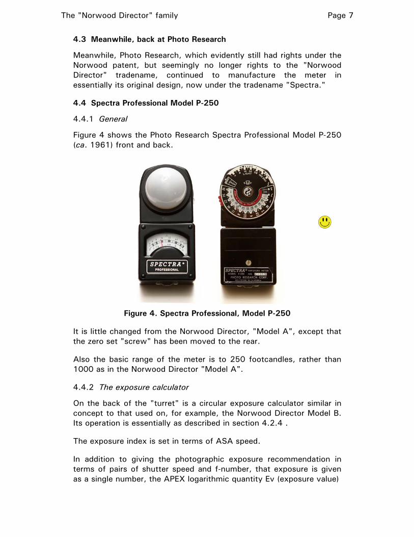
Figure 4 shows the Photo Research Spectra Professional Model P-250 (ca. 1961) front and back.
Figure 4. Spectra Professional, Model P-250
It is little changed from the Norwood Director, "Model A", except that the zero set "screw" has been moved to the rear.
Also the basic range of the meter is to 250 footcandles, rather than 1000 as in the Norwood Director "Model A".
4.4.2 The exposure calculator
On the back of the "turret" is a circular exposure calculator similar in concept to that used on, for example, the Norwood Director Model B. Its operation is essentially as described in section 4.2.4 .
The exposure index is set in terms of ASA speed.
In addition to giving the photographic exposure recommendation in terms of pairs of shutter speed and f-number, that exposure is given as a single number, the APEX logarithmic quantity Ev (exposure value)

The "Norwood Director" family Page 8
4.4.3 The range-multiplying slides
The meter is supplied with a two range-multiplying "slides", perforated metal plates that can be placed in a slot to lie between the hemispherical light collector and the actual photosensitive receptor. They attenuate the light by factors of 10 and 100, and thus multiply the measurement range of the meter by those factors. Since the basic meter scale runs to 250 footcandles, this allows the measurement of illuminance up to 25,000 footcandles.
4.4.4 The direct-reading feature
This model included provision for what is often described as the "direct reading" mode of the meter.
To support this, the meter face, in addition to the foot-candle scale, has a scale reading directly in f-numbers. This is not used in the basic mode of the meter (when the circular calculator is used).
A set of slides, similar to the range-multiplying slides, were supplied for use in this mode. (In fact the two range-multiplying slides were also used in this role.) Each slide was labeled with an ASA film speed, and were implicitly associated with the shutter speed 1/50 sec (the normal shutter speed in professional cinematography).
The photographer, knowing the ASA speed of the film being used (and assuming that the 1/50 second shutter speed is in fact applicable) chooses the slide marked with that film speed and inserts it. Now, after the meter measures the light, the recommended f-stop is read directly from the meter face. There is no need to use the exposure calculator.
If in fact the shot will involve a shutter speed other than 1/50 second, the slide to use for the shutter speed and film speed in use can be reckoned using a table in the manual.
4.4.5 The directivity pattern
Appendix B shows the directivity pattern of this model. It broadly corresponds with the classical cardioid pattern which is to be theoretically expected of an actual hemispherical receptor or its emulation with a hemispherical collector as in this meter.
4.5 Norwood Director Model C
4.5.1 General
In 1948, Paillard-Bolex established its own US distributorship, putting American Bolex out of that business. By now the manufacture and sale of the Norwood Director exposure meters had become prominent for American Bolex. Ezra Brockway, now presumably prohibited from
The "Norwood Director" family Page 9
using the "Bolex" name through loss of distributorship status, changed the firm's name to Director Products Corporation.
As a result, the Norwood Director meter became the Model C, but with no substantive changes. It said "Norwood Director" on the front and "Norwood Director" and "Director Products Corporation" on the back.
4.6 Norwood Director Model C Color-Matic
4.6.1 General
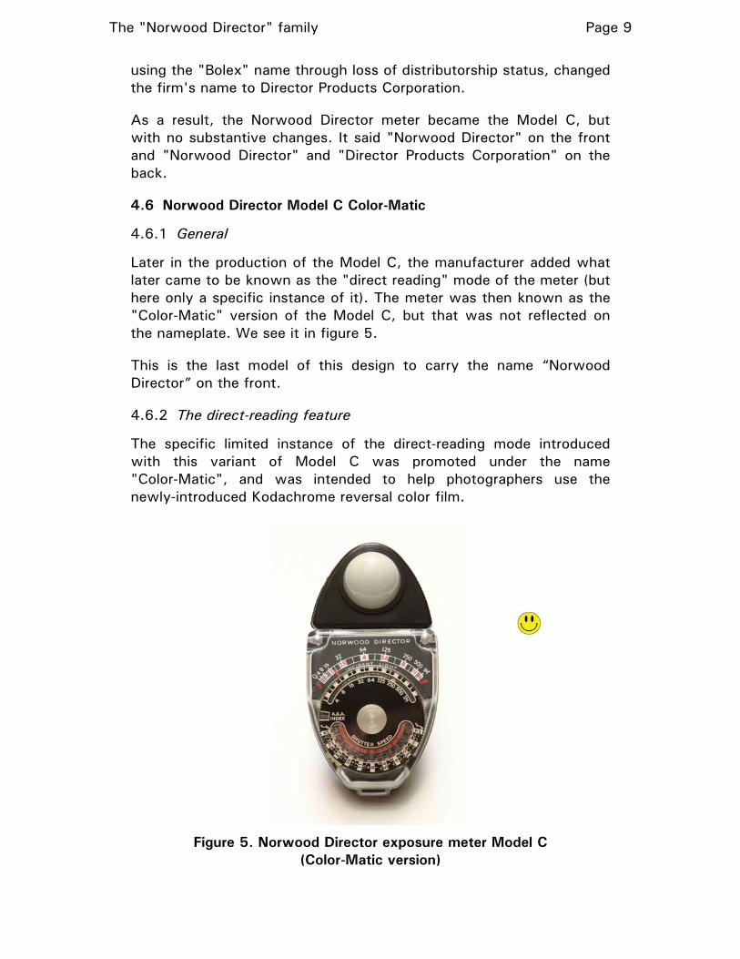
Later in the production of the Model C, the manufacturer added what later came to be known as the "direct reading" mode of the meter (but here only a specific instance of it). The meter was then known as the "Color-Matic" version of the Model C, but that was not reflected on the nameplate. We see it in figure 5.
This is the last model of this design to carry the name “Norwood Director” on the front.
4.6.2 The direct-reading feature
The specific limited instance of the direct-reading mode introduced with this variant of Model C was promoted under the name "Color-Matic", and was intended to help photographers use the newly-introduced Kodachrome reversal color film.
Figure 5. Norwood Director exposure meter Model C
(Color-Matic version)

The "Norwood Director" family Page 10
To support this, the meter face, in addition to the foot-candle scale, has a scale reading directly in f-numbers. This is not used in the basic mode of the meter (when the exposure calculator is used).
Also, the meter is provided with a special "direct-reading" attenuating slide, red in color, set up for "direct reading" with a film speed of ASA 10 (that of the Kodachrome film of the time) and a shutter speed of 1/50 sec (a common shutter speed for use with that film).
With this slide in place, after measuring the light, the recommended f-stop (predicated on the film speed and shutter speed) is read directly from the meter face. There is no need to use the calculator dial.
At a later time, sets of slides were made available (for use with this model and later models) to extend the "direct reading" functionality to other combinations of film speed and shutter speed. The photographer, knowing the speed of the film and the preordained shutter speed, chooses a slide marked with that combination of factors and inserts it. As before, after the meter measures the light, the recommended f-stop is read directly from the meter face.
4.6.3 The directivity pattern
Appendix B shows the directivity pattern of this model. It broadly corresponds with the classical cardioid pattern which is to be theoretically expected of an actual hemispherical receptor or its emulation with a hemispherical collector, as in this model.
Figure 6. Norwood Director Model D—"Director Products Corp."

The "Norwood Director" family Page 11
4.7 Norwood Director Model D—"Director Products Corporation"
The company later decided to adopt its new corporate name as the "marque" for this type of meter, which resulted in the Norwood Director, Model D (again with no substantive changes).
Figure Error! Reference source not found. shows a Norwood Director, Model D of this variety.
This model says "Director Products Corporation" on the front; on the back, it says "Director Products Corporation" and that the meter is a "Norwood Director Color-Matic exposure meter, Model D".
Except for the badging and nameplate changes, this model is indistinguishable from the Model C, Color-Matic version.
4.7.1 The direct-reading feature
As with the later ("Color-Matic") version of the Model C, this model includes provision for what later came to be known as the "direct reading" mode of the meter (but again here only a specific instance of it). (See section 4.6.2 for a full description.)
4.8 Norwood Director Model D—"Brockway"
For later production of the Model D, the company decided to use the marque "Brockway". Figure 7 shows a Model D of that variety.
This version says "Brockway" on the front; on the back, it says "Director Products Corporation" and that the meter is a "Norwood Director Color-Matic, Model D".
Figure 7. Norwood Director Model D—"Brockway"

The "Norwood Director" family Page 12
4.9 Model M2
The firm then changed its name to "Brockway Director Corporation", and this basic meter design became (without substantive change) the Model M2. It said "Brockway" on the front; the back said "Brockway Director Corporation" and that it was a "Norwood Director exposure meter, Model M2". We see it in figure 8.
Figure 8. Norwood Director exposure meter Model M2
Except for the badging and nameplate changes, this model is indistinguishable from the Model D.
This is the last model of this design to carry the “Norwood Director” name.
4.10 Overview of the era
As you can see, nothing really happened to the design of the meter during this era other than a lot of badge and nameplate changes to track changes in the corporate name and branding strategy of what I call, overall, "The Brockway Firm".
4.11 Norwood Director Model M3
The Norwood Director Model M3 (sometimes written "M-3") was made by Brockway Director Corporation beginning in 1952. We see it in figure 9.

The "Norwood Director" family Page 13
Figure 9. Norwood Director Model M3
This is a unique meter, quite small, and “despite its name” is not really a member of the “Norwood Director” family. It essentially only operates in a direct reading mode. A slide marked with the appropriate combination of exposure index and shutter speed is inserted. The meter reads the incident light, and the indication is directly in terms of the recommended f-number.
I will not discuss this model in detail.
5. ENTER SEKONIC
5.1 Introduction
The rights to the product were transferred in several stages from Brockway Camera Corporation (the final name of that firm) to Sekonic Electrical Co., Ltd., of Japan, which over the years made several models of this general design.
5.2 Brockway Studio S, Model S
The first model in this family made by Sekonic, introduced in 1957, was in fact presented as a product of Brockway Camera Corporation, and was known as the Brockway Studio S exposure meter (Model S). The motivation seemingly was that Sekonic was not, at the time, a name well recognized in the United States, while Brockway was well known because of this famous exposure meter line, for which there was an important and loyal user community.
Figure 10 shows a Brockway Studio S meter (Model S).

The "Norwood Director" family Page 14
Figure 10. Brockway Studio S (Model S)
This model differs little (other than in its livery and the design of the exposure calculator) from Model M2. It carries the name “Brockway” on the front. The rear nameplate says “Sekonic Studio S”, Brockway Camera Corporation, and “made by Sekonic Electric Company”.
This model came with a set of three direct-reading slides (one of which doubles as the "high range" slide).
It does include provisions for working with a single-value logarithmic exposure designation system used for a while on some Polaroid cameras. It also delivers the exposure recommendation in a form known as the LVS (Light Value System), a precursor to, and numerically identical to, the APEX exposure value, Ev.
5.3 The Sekonic Studio S, Model S
Next, however, essentially this same meter4 (with a change in the color of the meter dial and the outer ring of the calculator) became fully identified with Sekonic, and was then called the Sekonic Studio S (Model S). We see it in Figure 11.
4 However, the layout of the meter scale differed between the two models, suggesting that the Sekonic Studio S might use a different photocell and/or meter movement than the Brockway Studio S. And, perhaps as a result, the weight of the Sekonic Studio S is about 0.15 ounce less than that of the Brockway Studio S.

The "Norwood Director" family Page 15
Figure 11. Sekonic Studio S, Model S
It carried the name “Sekonic” on the front. The rear nameplate said “Sekonic Studio S” and “Sekonic Electric Company”.
We see the calculator meter scale and dial close-up in Figure 12.
Figure 12. Sekonic Studio S calculator dial
To set the exposure index, the main dial is held stationary and the silver center dial is turned with the use of a small post (seen in the figure at about 2 o'clock on the outside of the center dial) until the appropriate ASA speed appears in the ASA window.

The "Norwood Director" family Page 16
This "model pair" alone (among the true “Norwood Director” meters) uses a unique way of entering the meter reading into the exposure calculator.
Note first that, because the meter has the "direct read" feature, each "cardinal value" on the meter scale is marked with both a luminance value and a "direct read" f-number (e.g., 125 and 5.6).
To enter the meter reading into the calculator, the user moves the main calculator dial until an index line (there are actually two, marked "IN" and "OUT", for use with the high slide in or out) falls, on a secondary set of f-numbers on an adjacent dial, on the f-number found on the meter at the needle position (interpolating between the markings as needed).
In the figure, meter needle is at 250/8; thus the IN index has been set on the red number "8".
In effect, the "direct read" f-numbers on the meter scale are used as an arbitrary number for transferring the meter reading onto the calculator (not, as in all other meters of this family, the "footcandle" indication of the meter).
Using such a secondary set of f-numbers on the calculator, rather than a scale reading in footcandles, has an advantage: they also give the f-number recommended by the meter when the exposure time is indicated on a nearby scale marked in terms of cinematic frame rates (each of which implies an exposure time)–note "64", "32", "24" etc. in red at about 2 o'clock on the center dial.
Totally separate from this part of the calculator (at the opposite side of the main dial) are the familiar sets of adjacent exposure times (as shutter speeds) and f-numbers.
This whole thing is perhaps a bit "too clever", and is not found on later models, all of which use the meter indication in footcandles for transfer of the meter reading into the calculator.
The Sekonic Studio S was (in two variants) known in Japan as Model L-28/L-28A. We will see shortly the effect of this on the numbering of some future models for the U.S. market.
5.4 Sekonic Studio Deluxe, Model L-28C2
5.4.1 General
The Sekonic Studio S, known in Japan as Model L-28/L-28A, became the progenitor of the "L-28" series, which continued in the U.S. with the Studio Deluxe Model L-28c, introduced in 1964. An advanced version of the L-28A, called the L-28A2, was introduced in 1970.

The "Norwood Director" family Page 17
Also introduced in 1970 was an advanced version of the L-28c, called the Studio Deluxe Model L-28c2. It was produced until 1976. We see it in Figure 13.
The differences in the "-c" models were primarily an enlargement of the range of f-number covered by the calculator (plus, for the L-28c2, some similar changes in the range of some other scales).
Figure 13. Sekonic Studio Deluxe, Model L-28c
(L-28c2 essentially identical)
5.4.2 The needle lock feature
A new feature found in the Models L-28c and L-28c2 was a "needle lock", operated by a button in the center of the exposure calculator dial. With the button not depressed, the meter pointer is locked in its present position.
After the meter is properly oriented for the reading, the button is depressed until the needle settles and then released. Thus, the meter reading has been "captured", and the photographer is free to move to meter to where it could be most easily read and the photographic exposure reckoned on the calculator dial.
5.4.3 The collectors
Another new design feature in those two models is that the three collectors for the photoelectric receptor—the incident light hemisphere, the incident light diffuser disk, and the reflected light grid—which previously were mounted with a slip fitting, are now more conveniently mounted with a bayonet connection. These three elements, until now known as the Photosphere, Photodisk, and Photogrid, are now known as the Lumisphere, Lumidisk, and Lumigrid.

The "Norwood Director" family Page 18
5.4.4 The exposure calculator
There are a number of design changes in the exposure calculator dial. One is that there is now provision for setting the exposure index both in terms of ASA speed and also in DIN degrees (the German film rating system of the time, widely used in Europe). The ASA speeds are labeled at 1/3-stop intervals (making for a very cluttered scale). The exposure recommendation is also reported as the APEX value, Ev.
A prominent design improvement is the thick, "knob-like" main dial on the exposure calculator.
On the calculator, the dial that is tuned to set the exposure index has a small post to grasp to turn it. One need not hold the main dial to do this.
Here, to set the calculator to the meter reading, thus user turns the main dial to bring the footcandle value indicated by the meter, on a ring on the main dial, into alignment with an arrow on an adjacent ring. This same basic arrangement is found on the calculators on all subsequent models.
There are actually two arrows. One, white and marked "L", is used with the meter in its "low range” (i.e., with the high slide not in place). The other, red and marked "H", is used with the meter in its "high range) (i.e., with the high slide in place).
Figure 14. Direct reading slides for Model L-28c and L-28c2
Adapted from photo by John D. de Vries Used by permission
The "Norwood Director" family Page 19
5.4.5 Direct reading slides
A set of direct reading slides, in a nice leather case, came with this model. We see it in figure 14.
Some of the slides were functional duplicates. For example, there is a slide designated ASA 25, 1/30 sec and another one designated ASA 50, 1/60 second. They are identical in their behavior. The provision of the "duplicate" slides was to avoid either having multiple markings on the slide or expecting the user to recognize the equivalence.
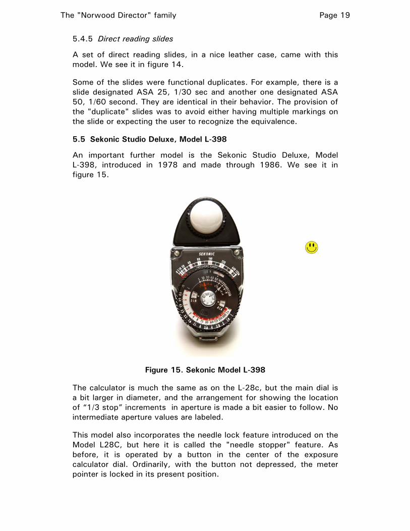
5.5 Sekonic Studio Deluxe, Model L-398
An important further model is the Sekonic Studio Deluxe, Model L-398, introduced in 1978 and made through 1986. We see it in figure 15.
Figure 15. Sekonic Model L-398
The calculator is much the same as on the L-28c, but the main dial is a bit larger in diameter, and the arrangement for showing the location of “1/3 stop” increments in aperture is made a bit easier to follow. No intermediate aperture values are labeled.
This model also incorporates the needle lock feature introduced on the Model L28C, but here it is called the "needle stopper" feature. As before, it is operated by a button in the center of the exposure calculator dial. Ordinarily, with the button not depressed, the meter pointer is locked in its present position.

The "Norwood Director" family Page 20
After the meter is properly oriented for the reading, the button is depressed until the meter needle settles and then released. Thus, the meter reading has been "captured", and the photographer is free to move to meter to where it can be most easily read and the photographic exposure reckoned on the calculator dial.
In this model, if it is not wanted for the meter needle to be locked when the "stopper" button is not pressed, the button can be pressed and turned a quarter turn clockwise, whereupon the button itself is locked down, in the "needle released" state.
As with the previous model, the exposure index can be set in terms of ASA speed or in DIN degrees. The ASA speeds are only marked at full-stop intervals. The exposure recommendation is also reported as the APEX exposure value, Ev.
On the calculator, the dial that is tuned to set the exposure index has a small pad of "corrugations" to use to turn it. This makes it less likely that this dial will be turned inadvertently, as it might be in the previous model where there was a small post on the dial.
The scale of the meter proper is labeled at different footcandle values than in previous models. This is a byproduct of the change in the incident light calibration constant, C, in this model from the previous value, 270, to 340 (see section D.3.3.4).
This changes the association of footcandle values and the f-numbers on the direct reading scale. The basic design of the scale is that each footcandle value that receives a label is associated with an f-number. Sekonic wanted to maintain the "standard" list of f-numbers, and thus the footcandle values chosen to receive labels had to change.
The "screw" on the rear to adjust the zero position of the meter is enlarged from the previous model and provided with a wider slot to allow it to be adjusted with a coin.
5.6 Sekonic Studio Deluxe II, Model L-398M
The next model in the series is the Sekonic Studio Deluxe II, Model L-398M. We see it in figure 16.
The major new feature of this model is the memo pointer, a small red pointer that can be set to "remember" a meter reading. It is especially useful when measuring two light sources to determine their illuminance ratio. It is moved with a thin ring located just below the main dial. The model number suffix “M” is in fact from “memo”.
The exposure index is entered in terms of ISO speed (essentially numerically equivalent to the ASA speed).

The "Norwood Director" family Page 21
The calculator has been rearranged in terms of “what moves with what.” The meter scale markings and calculator dial markings have been made larger for improved legibility. Calibration-wise, for the same meter indication in footcandles and exposure index, the exposure recommendation is about 1/6 stop less than for the L-398.
Figure 16. Sekonic L-398M
There is a small difference in the exact spacing of the values on the meter scale itself, a hint that this model uses a different meter movement than the L-398.5
The three collectors for this model, the Lumisphere, Lumidisk, and Lumigrid, are physically-distinguishable from those provided with mode L-398, even though they use the same bayonet-type attachment.6 The Lumisphere and Lumidisk of this set in fact have slightly different photometric properties, causing the L-398M to have a different value of its calibration constants than the L-398 (see section D.3.3.5).
The Lumigrid is improved over the Photogrid by having a transparent window, preventing dust from getting to the photocell though the grid holes.
5 Another clue is that the magnetic polarity of the meter magnet is seemingly reversed from that of the L-398, as noted from the external magnetic field.
6 Those for the L-28c and L-28c2 have 36 "teeth" and two white dots to show how the item should be oriented to engage the bayonet fitting. Those for the L-398M and L-398A have 30 teeth and one dot.

The "Norwood Director" family Page 22
5.7 Sekonic Studio Deluxe III, Model L-398A
The last meter so far of the principal family under discussion here is the Sekonic L-398A Studio Deluxe III. This model is still made by Sekonic (at this writing, $218.00 at B&H Photo-Video). We see it in figure 17.
Figure 17. Sekonic L-398A
Unlike all earlier models, which used selenium photocells, the L-398A uses an amorphous silicon photocell. Other than that, the L-398A is essentially identical to Model L-398M.
The model number suffix, “A”, is in fact from “amorphous”.
The exposure calculator is essentially identical to that of the L-398M.
As in Model L-398M, the exposure index is set in terms of ISO speed.
6. The Norwood Super-Director—another branch of the family tree
We now visit a "third branch" of the Norwood Director dynasty, made by a fourth entity, in which the "Norwood Director" name is (in a way) revived for a product.
In the later 1950s, Don Norwood founded a company called Helio-Tech, in Pasadena, California. There he developed a unique meter, known as the Norwood Super-Director, introduced in 1958. We see it in its later (and most common) version in figure 18. Its overall construction was very much a miniaturized version of the classic Norwood Director series of meters.

The "Norwood Director" family Page 23
It was actually manufactured and sold by the Japanese company Walz (perhaps founded by Norwood).
For incident-light exposure metering, the meter is equipped with the familiar Norwood-style hemispherical diffuser, known here as the Heliosphere. It mounts with a press fit.
Figure 18. Norwood Super-Director
This meter was highly oriented toward direct reading operation. Rather than utilizing a set of fixed attenuating slides to prepare it for use with different combinations of exposure index and shutter speed, there was instead an ingenious adjustable attenuating element, known as the Heliovalve, which was normally in place. We see it in Figure 19, both loose and in place in a Super Director meter.
With the lever on this set to a certain position (corresponding to a specific combination of exposure index and shutter speed), identified by a letter, the meter indication is directly in terms of f-number. For the basic Heliovalve, the range of letters is AA and then A through K. The higher letters correspond to less attenuation, and thus, in effect, to a lower meter range.

The "Norwood Director" family Page 24
Figure 19. Heliovalve
Adapted from photos by John D. de Vries Used by permission
There is, nevertheless, a circular exposure calculator of generally-familiar nature, which can be brought into the process when a more conventional modus operandi is desired (such as when the shutter speed cannot be preordained). In this case, the Heliovalve, if in place, serves to shift the range of the meter. The letter indicating the Heliovalve setting is set into a window on the calculator for proper coordination; with the Heliovalve out, the setting is "S".
There was available an alternate Heliovalve with a different range (letters L-P), intended for use with high-sensitivity film and/or low light levels. An earlier version of the meter was supplied with a black Heliovalve with a range of only C-K.
The meter can be equipped with a grid, known as the Heliogrid, to equip the meter for reflected-light metering.
In the reflected light mode (using the Heliogrid), the Heliovalve is removed, and there is no provision for extension of the meter range. The "valve" setting on the calculator is set to "F" to match the calculator to the photometric properties of the Heliogrid.
In the reflected light mode it turns out that for an exposure index of ASA 32 and a shutter speed of 1/50 sec, the meter is "direct reading"—the f-number recommendation can be read directly from the meter scale. That is really sort of an accident, but so we shouldn’t miss taking advantage of it, those specific predicates are marked on the Heliogrid.
The zero adjust "screw" is on the rear of the meter, under the nameplate, which must be removed to reach it.

The "Norwood Director" family Page 25
6.1 The Sekoninc Handi Lumi Model 246 illuminometer
Not a photographic exposure meter, the Sekonic Handi Lumi Model 246 illuminometer is “built on a Norwood Director chassis”. I discuss it in detail in Appendix F. (Yes, of course I have one.)
7. Back to the Photo Research branch of the family tree
Meanwhile, over the years, Spectra Cinema, Inc., successor to Photo Research, continued until at least 1998 to make, under the Spectra name, exposure meters little different in design from the Norwood Director "Model A", as well as variants with improved features.
They now manufacture sophisticated digital exposure meters, still generally utilizing the Norwood hemispherical collector principle for their incident light modes.
8. THE DOME LIVES ON
Sekonic also uses the Norwood hemispherical collector principle in many of their current digital exposure meters offering incident light metering, their overall designs however being dramatically different from the meters described above. Certain other manufacturers also continue to use the Norwood-concept hemispherical collector in their incident-light exposure meters.
9. THE CALIBRATION CONSTANTS
The matter of the calibration constants used in various models of this series is very complex. The matter is treated in detail in Appendix D.
10. Acknowledgements
Thanks to John D. De Vries for his extensive support in many ways of my learning about these exposure meters, and for the use of his excellent photographs.
His site has extensive information on the Norwood Director line of exposure meters. Here is a good place to start:
http://www.johndesq.com/director
Thanks again to James Ollinger for the wealth of information on his site about exposure meters. Much of my research was guided by that information.
His exposure meter site can be found here:
http://www.jollinger.com/photo/meters/meters/ge_dw68.html
#

The "Norwood Director" family Page 26
Basic Background in Photographic Exposure Metering
A.1 General
In photographic exposure metering, we use an instrument to measure either the light emitted by of reflected from the subject or the light falling on the subject, and from that, plus knowledge or assumption about the sensitivity of the film (or digital sensor) being used, the instrument issues a recommended photographic exposure, usually in the form of a collection of equivalent combinations of exposure time (shutter speed) and aperture (f-number). Two basic techniques are used.
Here is some basic information about this topic, pertinent to the discussions in the body of the article. It is beyond the scope of this article to discuss at length the details, relative advantages, and the limitations, of each technique.
A.2 Reflected light exposure metering
A.2.1 General
This is the technique used in most photography (especially "amateur" photography). In it, the instrument measures the average luminance of the scene (hopefully, with a field of view matching that of the camera). From that, plus the "exposure index" (what the photographer has told the meter is the sensitivity of the film or digital sensor), the meter issues a recommended photographic exposure.
The name of the technique comes from the fact that the luminance of the subject is often a manifestation of light reflected from it, although of course some subjects are self-luminous (the shade of a table lamp, for example).
A.2.2 The result
The result of a reflected light metered exposure (in a digital camera) is that the average photometric exposure on the sensor (over the entire image) is a certain fraction of the "saturation" photometric exposure. The fraction is largely a function of the value of K used by the meter (see section A.4 ).
A.2.3 Implications
The assignment of different photometric exposures (and thus different exposure results) to scene elements of different reflectance is dependent on the average reflectance of the scene.

The "Norwood Director" family Page 27
One impact of this is often summarized thus: A photo of a white cat on a snowdrift comes out looking like a gray cat on an ash heap; a photo of a black cat on a coal pile comes out looking like a gray cat on an ash heap.
A.3 Incident light exposure metering
A.3.1 General
In this technique, simplistically, the meter determines the illuminance of the light that illuminates the subject (the incident light). From that, plus the "exposure index", the meter issues a recommended photographic exposure.
A.3.2 The result
The result of an incident light metered exposure is that, if all elements of the scene are equally illuminated, the photometric exposure given each element of the scene is proportional to its individual reflectance.7 The exact proportional relationship is largely a function of the value of C used by the meter (see section A.4 ).
A.3.3 Implications
One impact of this technique is often summarized thus: A photo of a white cat on a snowdrift comes out looking like a white cat on a snowdrift; a photo of a gray cat on an ash heap comes out looking like a gray cat on an ash heap; a photo of a black cat on a coal pile comes out looking like a black cat on a coal pile.
A.4 Exposure equations and calibration constants
In each case, the development of a photographic exposure recommendation is done following a straightforward linear equation. The exact relationship between a certain combination of measured luminance or illuminance, plus a certain exposure index, and the issued photographic exposure recommendation is controlled by an exposure metering calibration constant, which has the symbol K for the reflected light mode and C for the incident light mode.
The greater the value of K [or C], then for a given average scene luminance [or illuminance on the scene], and a given exposure index, the greater will be the recommended photographic exposure.
No "correct" value for K or C can be derived mathematically, owing to the fact that there can be different "strategies" with regard to the
7 This is very similar to the underlying concept of the “Zone System”, a scheme of exposure planning popularized by famed photographer Ansel Adams and others.
The "Norwood Director" family Page 28
desirable exposure result. Thus, over the years, exposure meter manufacturers have each chosen a value of K and or C for their exposure meters based on their own thoughts as to what value will produce exposure results they feel their users will most often enjoy.
That having been said, in recent decades, most exposure meter manufacturers have used fairly consistent values of K and/or C.
More information on these calibration constants is given in Appendix D.
A.5 Directivity patterns
Of considerable importance to the specific performance of incident light exposure meters is the matter of the meter's directivity pattern. This is a plot, in polar coordinates, of the relative response of the meter to a light beam of any given "potency" for different angles of arrival of the beam.
We see these for certain meters discussed here in Appendix E.
#

The "Norwood Director" family Page 29
Appendix B
Norton's explanation of the principle of his meter
When Donald W. Norton's new concept for an incident light exposure meter was first seen, there was doubtless much curiosity among the more technically-minded photographers as to just how did it work to provide in a single measurement in the incident light mode an exposure indication that would give a desirable exposure result over a wide range of lighting situations
My own experience shows that no technical model of its working would show how this happens. And this matter was complicated by the fact that there was no clear and uniform objective criterion, applicable to the various photographic tasks and artistic styles of lighting, by which we could "score" how good was the exposure result of a particular shot.
In 1950, Norwood delivered a paper to the Society of Motion Picture Engineers which, in part, discussed a series of perceptual tests that seemed to shed light on the benefits of the Norwood-principle light meters.
The test program related solely to a particular photographic situation, one in fact of great interest to cinematographers and as well to portrait photographers. This situation was the illumination of a human face by two light sources, one (the "key light") typically aimed at the subject from some angle to the side, and the other (the "fill light") typically aimed at the subject from above or just alongside the camera.
According to Norwood's summary, as we moved the key light in its angle from the camera, we find that the photographic exposure that was needed to give a consistently-desirable exposure result (in the consolidated opinion of multiple human observers of test images taken with various exposures) followed linearly the angle of the key light location (reaching twice the exposure needed for a "head-on" key light when the key light was at an angle of 90° (direct to the side).
Norwood now considered the determination of the optimum photographic exposure to be used by a single measurement with an incident-light exposure meter. Based on the finding mentioned above, he concluded that the ideal directivity pattern for the meter was the reciprocal of that linear function. That would be in fact a curve called an Archimedean spiral.
Sadly, this reasoning was a bit in error, as it did not take into account the effect of the fill light on the meter reading. Thus the theoretically-ideal directivity pattern of the meter was a bit different than an Archimedean spiral.

The "Norwood Director" family Page 30
Next, Norwood considered the theoretical directivity of a hemispherical-receptor exposure meter, based on an analysis of its projected area from different angles. He concluded that this theoretical directivity also followed an Archimedean spiral.
Sadly, his geometric model was a bit in error. In fact, the theoretical directivity pattern of a hemispherical receptor meter (or equivalent) is a curve called a cardioid.
Next, Norwood pointed out that since:
• The desirable meter directivity to give a consistently optimal exposure recommendation was an Archimedean spiral (not so), and
• The theoretical directivity of a hemispherical-receptor meter is an Archimedean spiral (not so)
a hemispherical receptor meter would consistently give an optimal exposure recommendation.
Thus, says Norton, we can see why the Norton-principle meter is so good at its job.
Now, all forensic cynicism aside, the discrepancies in Norwood's presentation were not large (we will see this shortly in a figure). This is after all, in any case, a very imprecise notion at best. Thus in fact his demonstration does in fact give us good insight into how Norton's meter do that voodoo that it do so well.
Figure 20 shows, for comparison, the various curves involved in Norwood's presentation.
Figure 20.

The "Norwood Director" family Page 31
The red curve is the meter directivity actually needed to fulfill Norton's concept of the optimal photographic exposure for different positions of the key light. Norwood said that would be an Archimedean spiral. The black curve is the Archimedean spiral that fits that story. The blue curve is a cardioid, which is the theoretical directivity of a hemispherical-receptor meter; Norwood suggested that its directivity would be an Archimedean spiral.
#

The "Norwood Director" family Page 32
Appendix C
The “footcandle” readings
In all the meters in the classical “Norwood Director” line8, the meter proper gives an indication in footcandles, a non-SI unit of luminance.
In general, the meter indication in this form is used to transfer the meter indication into the exposure calculator.
We must recognize that with the meter in its hemisphere mode, it does not truly respond to illuminance, since its directivity pattern is not the cosine pattern that is theoretically needed for the meter to respond rigorously to luminance. This is not a flaw; this is just a corollary of the use of the cardioid pattern to practice the Norwood principle of incident light exposure metering (see Appendix B). Thus, in the hemisphere mode, we must consider an indication that seems to be in footcandles as just an arbitrary number.
However, if we consider an illumination all of which arrives “head on” (that is, with angle of incidence 0, where both cosine and cardioid directivity functions have the same value, 1), we might expect the meter indication to correspond to the illuminance offered by that illumination. We might expect the meter manufacturer to arrange the exposure calculator so this would be true (else why mark the meter scale in footcandles rather than some unlabeled arbitrary number).
With the meter in its dome mode (with a cosine directivity pattern), but again used with the calculator to determine exposure in certain cases (where actual illuminance is considered the best predicate for exposure determination), the meter reading, apparently in footcandles, is again really just an arbitrary vehicle for transferring the meter indication into the calculator.
Nevertheless, we might expect the meter manufacturer to have arranged things so that this reading is in fact the bona fide illuminance of the illumination the meter senses.
However, there is a clinker with regard to these two “reasonable expectations”. The hemispherical and disk light collectors in these meters have different photometric transfer coefficients. That is, for the same head-on illumination, they will afford a different stimulus to the actual photocell of the meter, and thus lead to a different meter reading. The difference is generally on the order of 1/6 to 1/2 stop (in photographic terms).
8 This excludes the Norwood Super-Director.

The "Norwood Director" family Page 33
Thus the meter cannot be designed to fulfill both of our expectations above.9
Now we consider the third task of these exposure meters, to actually measure illumination not to make a photographic exposure determination but rather to, for example, determine the illumination on a work surface in connection with workplace lighting design issues.
This again is done with the meter in its disk mode, but now the meter indication (in footcandles) is the final result.
Because of this, it is reasonable to think that the manufacturer will arrange the whole scheme of the exposure meter so that in the disk mode the meter indication will in fact be the actual illuminance.
If that were so. it means that if we consider the meter in its hemisphere mode, and imagine a test illumination, head-on, with a certain luminance, the meter will not give a reading that corresponds to that illuminance. And that is just fine. In the hemisphere mode, we only use the meter to determine photographic exposure, and the meter reading, “in footcandles”, can be considered just an arbitrary number.
All this having been said, it turns out that having the meter give a “proper” footcandle reading in the disk mode is not generally true for the meters discussed here.
#
9 It could if the meter reading was entered into the calculator with a different “pointer” for the hemisphere and disk modes, but such is not so for any of the meters discussed here.

The "Norwood Director" family Page 34
Appendix D
The calibration constants
D.1 Background
D.1.1 Introduction
The exposure meter calibration constants, K and C, are design parameters of an exposure meter. They determine what exposure recommendation the meter will issue for a certain measured scene luminance (for the reflected light mode) or incident illuminance (for the reflected light mode) plus a certain exposure index. K pertains to the reflected light mode and C to the incident light mode.
For a given measured scene luminance or incident illuminance, and a given exposure index, a higher value of K or C will result in the meter issuing a larger recommended photographic exposure.
The international standard for free-standing photographic exposure meters admits a wide range for either K or C. This is because there is no inherently "correct" photographic exposure for any situation, and different manufacturers wish to be able to adopt different values of K and C based on their pragmatic, empirical thoughts as to what values will "make most users happy with the result most of the time".
Often today manufacturers will adopt either 12.5 or 14 as their anointed value of K.
D.1.2 Different values of C for the different directivity modes
In the international standard, different ranges of C are "permitted" for meters using a cosine directivity and meters using a cardioid directivity. The ranges differed by about the ratio 3:4 (cosine:cardioid), from which we might infer that it is seen as appropriate, for a meter having both directivity modes, to have the values of C for the two modes follow that ratio.
Following that "hint", Sekonic, the manufacturer in recent times of the meters of interest here, has as its corporate norms (but not necessarily applicable to the meters discussed here) a C of 340 for hemisphere operation and 250 for disk operation.
D.1.3 Implementation
In a meter of the overall construction of those described in this article, there are two likely ways to attain a different value of C for the hemisphere and disk configurations (I will assume that a 4:3 ratio is wanted):
The "Norwood Director" family Page 35
• The photometric transfer constant of the disk collector would be
4/3 that of the hemisphere collector. That is, for the same "head on" illumination, the disk collector would give 4/3 as much stimulus to the meter's photocell as the hemisphere collector. This would result in a C of 3/4 as much as with the hemisphere collector.
• The two collectors could have the same photometric transfer coefficients, but on the exposure calculator, there would be separate "pointers" used for the entry of the meter reading into the calculator in the two modes (differing in their positions by about 0.42 stop).
In the meters under discussion:
• The photometric transfer coefficient of the disk collector is less than that for the hemisphere collector. (This by itself would make the value of C for the disk mode be greater than that for the hemisphere mode.)
• The same "pointer" is used in both modes to enter the meter reading into the exposure calculator.
Thus we realize that no meter of this family cannot have values of C for the disk and hemisphere modes that follow the "hint" of the international standard (nor in fact the general corporate norms of the manufacturer of the later models, Sekonic).
D.2 The “calculator C”
We can, by “reverse engineering” the exposure calculator, determine the value of C intended by the meter designers if we stipulate that the meter reading, in footcandles, accurately reflects the illuminance upon the meter (assuming head-on incidence). I refer to the value of C discerned by this process as the “calculator C”.
In reality, it is often not possible to determine this value precisely. One reason is that there are often inconsistencies in the layout of the various scales on the calculator dials. For the calculator to work “ideally” in its task as a circular slide rule working the exposure equation, the angular distance between two marks corresponding to values of a photographic variable that are separated by “one stop” (i.e., the distance between the mark for “1 second” and “2 seconds”, or the distance between the marks for apertures of f/1.0 and f/1.410) should be consistent for the entire calculator.
10 Actually, that mark represents an aperture of f/1.414…, but is by custom labeled “f/1.4”.

The "Norwood Director" family Page 36
But often we find this not to be the case, Individual marks may be displaced from their “theoretical” positions. In some case, the “one stop spacing” is fairly consistent over each of two scales but differs slightly between them.
Thus in many cases, the result of a determination of the “calculator C” will depend on just which arbitrary “test case” is used to investigate the calculator.
The range of results is in some situations as great as “1/3 stop”. That would mean that if on a particular meter, for one test case, we got a calculator C of 303, in another test case we might get a value of 382!
A second clinker in this matter is the critical assumption that the meter reading, in footcandles, accurately reflects the illuminance upon the meter (assuming head-on incidence).
We have seen in Appendix C that, if the manufacturer chooses to have the “footcandle” indication be correct in the disk mode (so that actual luminance readings will be correct), then the footcandle reading in the hemisphere mode cannot be (even for the “clean” head-on illumination) correct. But we do not know for certain that is what the manufacturer has chosen.
Thus we can make only limited use of the determination of the “calculator C”.
D.3 Stated value(s) of C for specific meter models
D.3.1 Norwood Director Model A
We do not have enough information to ascertain the intended values of C or K for this meter.
D.3.2 Spectra Professional P-250
Reverse engineering of the exposure calculator dial indicates that the intended value of C is approximately 25 (in footcandle terms), or 270 in SI units. 270 is today a widely used value of C, but for meters with a cosine response. Here we have essentially a cardioid response, for which today a C of 340 is common.
We have not yet determined the value of K (for the reflected light mode) for this meter.
D.3.3 "Brockway/Sekonic" era meters
D.3.3.1 Norwood Director Models B, C, D, and M2
No value of C or H is noted on the nameplates of these meters nor mentioned in the manuals. It is likely that the intended value of C was

The "Norwood Director" family Page 37
consistent for these models. Reverse engineering of the Norwood Director Model D suggests that the intended value of C is approximately 25 (in footcandle terms), or 270 in SI units.
Some of the later units of this series in fact indicate on the nameplate that the value of C is 25 (again, in footcandle units).
This value is presumably stated for the hemisphere mode. Based on the photometric characteristics of typical hemisphere and disk collectors used on these models, it is likely that the value of C for the disk mode is about 30% higher.
We have no information on the value of K for these models.
D.3.3.2 Studio S (Brockway and Sekonic branding)/L-28
The nameplate indicates "C=25", This is in footcandle units. The SI equivalent is probably intended to be 270. The manual indicates the same ("Dial constant C=25").
This value is presumably stated for the hemisphere mode.
We have no information on the value of K for these models.
D.3.3.3 Models L28c and L-28c2
The nameplate indicates "C=25", This is in footcandle units. The SI equivalent is probably intended to be 270. The manual indicates the same.
This value is presumably stated for the hemisphere mode.
The manual states the value of K as 1.15 (in cd/ft2 terms). That would be about 12.4 in SI units.
D.3.3.4 Model L-398
The nameplate of Model L-398 indicates that the value of C is 340. The manual for this model, in its specifications section, also gives the value of C as 340. This is a change from earlier models (where the announced value of C was essentially 270).
We assume this is for the hemisphere mode.
We believe this change was made by Sekonic for conformity with the value of C they had standardized in other parts of their product line for cardioid-pattern incident light exposure meters. The change does not, however, bring full conformity with those norms, which prescribe a different value of C for the "cosine" mode where provided (see section D.3.3.5).

The "Norwood Director" family Page 38
In fact, we estimate that for the disk mode, the value of C is about 19% higher than for the hemisphere mode.
It has been reported that typically Model L-398A meters were actually adjusted at the factory so that in the hemisphere mode they "read high" on a footcandle basis by perhaps 1/3 stop. As a result, the actual value of C was about 270 (the announced value for the precious model).
The value of K for this model is stated in the manual as 12.5.
D.3.3.5 Model L-398M
A single value of C, 340, is stated both on the meter nameplate and in the specifications section of the manual.
We presume that to be for the hemisphere mode. We estimate that for the disk mode, the value of C is about 30% higher than for the hemisphere mode.
The value of K for this model is stated in the manual as 12.5.
D.3.3.6 Model L-398A
The nameplate for this model states "C=340". The (English language) manual, in its specifications section, states that the value of C when using the Lumisphere configuration is 340 and for the Lumidisk configuration it is 250. The value of K is stated in the manual as 12.5.
This is all fully consistent with the values stated for other contemporary exposure meters in the Sekonic line.
But we know that the actual values of C for the two modes cannot be those values (see section D.1.3 ).
This is the first model in this family for which different values of C are stated for the hemisphere and disk configurations. But we know that the actual values of C for the two modes cannot be those values (see section D.1.3 ).
And in fact the Sekonic online specifications state that the value of C for the Lumisphere mode is 340, and does not state a value for the Lumidisk mode. We've just seen why that probably is.
If in fact the value of C for the hemisphere mode is 340, we estimate that for the disk mode it is about 30% higher (i.e., perhaps 440, far from 250). This is no doubt why Sekonic does not state a value of C for the Lumidisk mode of this model in current literature.
#

The "Norwood Director" family Page 39
Appendix E
Directivity patterns
This is the measured (horizontal plane) directivity of a Spectra Professional P-250 exposure meter (in its hemisphere configuration). The theoretical cardioid pattern is also shown for comparison.
This is the (horizontal plane) measured directivity of a Norwood Director Model C (ColorMatic version) exposure meter (in its hemisphere configuration). The theoretical cardioid pattern is also shown for comparison.
#

The "Norwood Director" family Page 40
Appendix F
A cousin to the Norwood Director: The Sekonic “Handi Lumi” Model 246 illuminometer
F.1 BACKGROUND
When a “Norwood Director” is configured with its disk-oid collector (e.g., the Lumidisc), the meter indication is very nearly proportional to the actual illuminance upon the plane of the collector.
When using the mater for photographic exposure determination, the meter indication, in foot candles, is not itself the result the user seeks but rather is used to transfer the meter indication to the exposure calculator. We can think of the meter reading itself as being on an arbitrary scale, albeit marked in footcandles.
The manual points out that one use that can be made of the meter in that configuration is to measure the illuminance of the incident light on a surface, not in connection with photographic exposure determination, but in such contexts as determining if that ambient illuminance is the desired one at a work table on which photographic prints are to be critically examined.
In that use, the footcandle indication given by the meter needle is the result the user seeks.
But sadly, in many Norwood Director meters, this footcandle indication departs significantly from the illuminance being observed. This is not a result of “sloppy calibration” of the meter during manufacture. Rather it is the result of curious choice of parameters of the meter design. (The typical degree of discrepancy varies with the meter model.)
Shocked? Disappointed? Baffled? Sure. “Go figure”.
10.1 The Sekonic “Handi Lumi” Model 246 illuminometer
10.1.1 General
Perhaps in recognition of this less-than-ideal situation, or more likely just to provide serious users of illuminance measurement with a purpose-built tool, Sekonic introduced the “Handi Lumi” (is that Japanese or what!) Model 246 illuminometer. We see it in figure 21.
As you can see, this is designed around the “chassis” of a typical Norwood Director exposure meter.

The "Norwood Director" family Page 41
Figure 21. Sekonic “Handi Lumi” model 246 illuminometer
10.1.2 The scale units
For the American market, this model could be ordered with the scales denominated in foot candles or lux. For the Japanese market, only the lux version was available (in part owing to the strict Japanese “metrication” laws).
We will describe the working of the scales in terms of the foot candle version (as seen in Figure 21).
10.1.3 The “medallion”
In a Norwood Director exposure meter, the space below the meter dial is filled with the circular exposure calculator. There is of course no such thing in a Model 246. But if Sekonic had used essentially the same wholly-transparent front housing as in the Norwood Director meters, we would have for the lower part of the instrument a nice view of the innards of the meter movement, fascinating to me but not really stylish. And if they had actually used the very same housing part, it would have had in its center one or more holes by which the exposure calculator would have been mounted, certainly nikulturniy.
Rather than designing a wholly-new front cover part, Sekonic decided to replace the exposure calculator with a stylish circular “medallion”, reminiscent of a tiny fancy drink coaster with a pebbled leather insert.
I think the resulting overall design of the meter is charming, in a “art deco” sort of way.
10.1.4 Meter ranges
The basic configuration of the meter is with a disk-type light collector in place (referred to in the manual as a “Lumidisc”). It is similar to the

The "Norwood Director" family Page 42
Lumidisc provided with the Model L-398 exposure meter (and like it has a bayonet mount). However, it is different as to the profile of the white collector proper, which rises slightly above the mounting ring rather than being slightly underflush with it as in an L-398 Lumidisc. My guess is that this is to give the meter a directivity pattern than more closely follows the ideal cosine pattern that that of the exposure meters in their Lumidisc mode.
The basic collector also includes a color compensation filter (which appears greenish in color). (See section 10.1.5 .)
In this configuration, the meter scale (the black one is applicable) runs from 0 to 500 footcandles.11
The meter scale is approximately linear with illuminance over most of the range. This is in distinction to the Norwood Director exposure meters, in which the scale is roughly logarithmic with illuminance over most of the range (which fits better photographic use, where we think of changes in “stops”). This difference no doubt comes about through changes in the shape of the magnet pole tips in the meter movement.
For higher illuminance levels, the user inserts into a slot just behind the Lumidisk a “10X” slide, a perforated metal plate that attenuates the light by a factor of 10 on its way to the photocell. (This is conceptually identical to the “high slide” provided with Norwood Director exposure meters. But that has an attenuating factor of 32.)
The result is that the range of the meter is now 0-5000 footcandles12. The black scale is read and the reading multiplied by 10.
For lower illuminance levels, the regular Lumidisk collector is removed and replaced by a special “low range” one. Its photometric transfer coefficient is 5 times that of the normal Lumidisk. We can recognize it in that it has two red, rather than white, dots to indicate its proper alignment with the bayonet mount when mounting the collector. It also does not have the greenish-looking incorporated filter (presumably how it comes to have a higher transfer coefficient).
Because of its higher photometric transfer coefficient, with it in place the meter sensitivity is 5 times normal. Thus the meter range is 0-100 foot candles.13 The luminance reading is taken directly from the red scale on the meter face.
11 In the lux-denominated version, 0-5000 lux.
12 In the lux-denominated version, 0-50,000 lux.
13 In the lux-denominated version, 0-1000 lux.

The "Norwood Director" family Page 43
The 10X slide is not used in connection with the “low range” Lumidisc collector.
10.1.5 Color compensation
The basic Lumidisc collector provided with this model includes a filter (looks greenish) such that, with this collector in place, the overall spectral response of the instrument (the “weighting” it gives to light components of different wavelengths) is essentially that prescribed by CIE norms for the determination of illuminance.
The low-range Lumidisk does not include such a filter (which has a significant “attenuation” at all wavelengths), so as to have the higher photometric transfer coefficient needed to give the meter its lower range.
Accordingly, when measuring light from different common source types, a correction factor from a table in the manual is applied (based on the typical spectral distribution of sources of that type). The amount of correction needed is quite modest. The factor used to apply the correction runs from 0.8 to 1.1, 1.0 being “no correction”. For incandescent or normal fluorescent lighting, the factor is in fact 1.0.
#