northern telecom practices section 363-2011...
TRANSCRIPT

NORTHERN TELECOM PRACTICES SECTION 363-2011-300 Issued: 78 11 10
Standard N
DMS-1* DIGITAL MULTIPLEX SYSTEM SYSTEM OPERATION
I.
2.
3.
4.
CONTENTS PAGE
GENERAL .••••••••••••••••••••••• I
ALARMS •••.••••••••••••••••••••• I
Charts 1. RCT Alarm Display Operation .... 3 2. CCT Alarm Display Operation . ... 4
CONTROLS ••••••••••••••••••••••• s Charts
3. Power Supply Reset . • . • . • • • • • • • . s 4. System Controller Restart .••.••••. 6 s. Protection Switching, Bypass,
and Loopback . • • . • . • . • . • . • • . • . • 6 6. Traffic Measurement . • . • . • . • • • • . • 10 7. Priority/Dedicated Selection .••.••. II
TEST ACCESS •••••••••••••••••••• 12
Charts 8. QPP425 System Test Circuit Pack
Calibration and Tests . • • • • • • • • . • . 23 9. QPP424 Line Test - Office
Circuit Pack Operation . • . • • • • • • • . 28 10. QPP450 Test Control Circuit
Pack Tests . • • . • . • • • • • . • • • • • • • . 31 11. QPP448 Test Access Circuit
Pack Operation . • • • . • . • • . . • • • • • . 34
S. ORDER WIRE • • • • • • • • • • • • • • • • • • • • 37
Charts 12. Initiating a Call at an RCT . • . . • • . 37 13. Initiating a Call from a Repeater
Site . • . . . • • . • • • • • • • • • • • • • • • • • . 38 14. Answering a Call at the CCT .••.. 39
6. EMERGENCY POWER • • • • • • • • • • • • • 40
Charts 15. Connecting and Removing an
Emergency Generator at an RCT 40
7. DIGITAL LINE FAULT LOCATION • • • • • • • • • • • • • • • • • • • • • • • 41
• DMS-1 is a trademark of Northern Telecom Limited
I. GENERAL
1.01 This section outlines procedures required for the operation of the DMS-1 Digital Multiplex
System. The information contained in this section is supplementary to the descriptive and maintenance practices.
1.02 Reason for Reissue: to add new and revised information.
1.03 The DMS-1 system normally operates automatically. The monitor and alarm circuits
within the system detect and indicate any degradation in performance or any equipment failure. When the system is functioning correctly and all input signals are present, there are no visual or audible alarms. When the system detects trouble, office alarms, remote alarms, and equipment alarms are activated.
1.04 The indicators on the faceplates of the alarm circuit packs (Fig. 1 and 2) are used as a f~rst
step in fault location. The functions of these indicators are described in 363-2011-500.
1.05 Controls on the faceplates are used for adjustments, system testing, and fault
location.
2. ALARMS
2.01 Most RCT alarms are displayed on the QPP420 ALM REM circuit p_ack (Fig. 1).
The Remote Concentrator Terminal (RCT) alarms are also transmitted to the Control Concentrator Terminal (CCT) and displayed on the QPP421 ALARM OFFICE circuit pack together with CCT alarms. In addition to the centralized alarm display, failure of the initial or the backup circuit pack, where optional backup circuit packs are installed, is indicated by a light on the QPP431 SYS CONT and QPP426 RING GEN.
®Northern Telecom Limited 1977 Printed in Canada
Page 1 41 Pages

SECTION 363-2011-300
I I ALM REM
LP
I"' •
DFA . DFB . LFA .
LFS .
ltFP .
LPF .
RMJ . RMN . CPF .
AC . SAT . TEM . DOOR .
i FUSE .
• • • • ON
OFf
Fig. 1 - QPP420A ALM REM Circuit Pack
Page 2
I
ALARM OFFICE
• II'ITCE ~· ALM i
l . OCP FAIL - A
l . DCP FAIL- 8
liNE FAll- A
4 . LJN£ fAll-8
S. liHE fA IL-P
6 . 8YPASS DP
7. LP8K DP
S . T BAT
9 . L1NE PW;
lO . RINC CEN
ll . COM PWR u• •c FAtL
ll . 8AT fAll
14 . 0YER TE"P
lS . DPEN OODR
16 . RINC OIST F
11 . HUL T LOC
18 . ll OET fA IL
19 . SYS CO NT
lO • H. n •
23 •
ER QPP421A
Fig. 2 - QPP421 ALARM OFFICE Circuit Pack

SECTION 363-2011-300
CHART I RCT ALARM DISPLAY OPERATION
This chart describes the operation of the LP TST button and display ON/OFF switch on the QPP420 ALM REM circuit pack at the RCT.
STEP PROCEDURE
1 Switch the display ON/OFF switch to the ON position.
Requirement: If there are any alarms, the corresponding indicator shall light.
2 Press and hold the LP TST button on the QPP420 circuit pack.
Requirement: All indicators shall light while the button is pressed.
3 Release the LP TST button.
4 Switch the ON/OFF switch to OFF.
Requirement: No alarm indications on QPP420.
If any of the requirements are not met, replace the QPP420 circuit pack.
Page 3

SECTION 363-2011-300
CHART 2 CCT ALARM DISPLAY OPERATION
This chart describes the operation of the controls on the QPP421 ALARM OFFICE circuit pack at the CCT.
STEP PROCEDURE
A. ACO Operation
When an office alarm is caused by the DMS-1 system, press the ACO button (Fig. 2).
Requirement 1: The audible office alarm must stop ringing.
Requirement 2: The visual office alarm must go out.
Requirement 3: The bay alarm light must go out.
Requirement 4: The alarm indication on the ALARM OFFICE display must remain lit.
B. Display Selection
Note: When an office alarm is caused by the DMS-1 system, one of the four RCT lamps or the CCT lamp on the QPP421 circuit pack must light.
2 Press and hold the LP TEST button.
Requirement: All indicators shall light while the button is pressed.
If the requirement is not met, replace the QPP421 circuit pack.
3 Release the LP TEST button.
Requirement: All indicators shall go out.
4 Switch the MTCE ALM switch on the QPP421 to the ALM position.
5 Tum the RCT/CCT selector until the pointer is pointing to the indicator which is lit.
Requirement: One or more indicators on the QPP421 circuit pack must light.
6 If the FAULT LOC lamp is lit, switch the MTCE ALM switch to the MTCE position and the RCT/CCT selector to the indicator which is then lit.
Page 4
Requirement: LED indicating the faults must light.
Note: Refer to 363-2011-500, Fig. 1 for interpretation of the alarm and maintenance lights.

SECTION 363-2011-300
3. CONTROLS
CHART 3 POWER SUPPLY RESET
This chart describes the steps to be carried out to restore the QPC85 5/12-V converter and QPP439line power converter to operation after replacement or repair of a system fault causing an over-current condition.
STEP PROCEDURE
1 On the fuse panel check the 48-V supply fuse for the converter.
Requirement 1: The fuse current rating must match the value indicated on the fuse panel, and the colored indicator on the fuse must match the colored insert in the fuse holder.
Requirement 2: The fuse indicator must not protrude from the face of the fuse.
2 Check the QPP420 at the RCT or the QPP421 at the CCT as applicable.
Requirement 1: The CPF (at RCT) or COM PWR (at CCT), or the LPF (at RCT) or PWR (at CCT) indicator must be lit.
Requirement 2: The FAIL indicator on the line power converter must light if the line power converter has failed.
3 Press the RESET button on the faceplate of the power converter.
Requirement: The indicators on the alarm display and the FAIL indicator on the line power converter (if applicable) must go out.
If the requirement is not met or a fuse blows, refer to 363-2011-500, Flowchart 6 (for a line power converter) or Flowchart 8 (for a common power converter), for locating and correcting the fault.
4 Release the RESET button.
Page 5
SECTION 363-2011-300
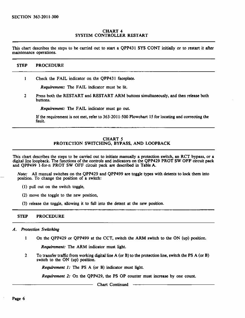
CHART 4 SYSTEM CONTROLLER RESTART
This chart describes the steps to be carried out to start a QPP431 SYS CONT initially or to restart it after maintenance operations.
STEP PROCEDURE
Check the FAIL indicator on the QPP431 faceplate.
Requirement: The FAIL indicator must be lit.
2 Press both the RESTART and RESTART ARM buttons simultaneously, and then release both buttons.
Requirement: The FAIL indicator must go out.
If the requirement is not met, refer to 363-2011-500 Flowchart 15 for locating and correcting the fault.
CHART 5 PROTECTION SWITCHING, BYPASS, AND LOOPBACK
This chart describes the steps to be carried out to initiate manually a protection switch, an RCT bypass, or a digital line loopback. The functions of the controls and indicators on the QPP429 PROT SW OFF circuit pack and QPP499 1-for-n PROT SW OFF circuit pack are described in Table A.
Note: All manual switches on the QPP429 and QPP499 are toggle types with detents to lock them into position. To change the position of a switch:
(1) pull out on the switch toggle,
(2) move the toggle to the new position,
(3) release the toggle, allowing it to fall into the detent at the new position.
STEP PROCEDURE
A. Protection Switching
Page 6
On the QPP429 or QPP499 at the CCT, switch the ARM switch to the ON (up) position.
Requirement: The ARM indicator must light.
2 To transfer traffic from working digital line A (or B) to the protection line, switch the PS A (or B) switch to the ON (up) position.
Requirement 1: The PS A (or B) indicator must light.
Requirement 2: On the QPP429, the PS OP counter must increase by one count.
Chart Continued

SECTION 363-2011-300
CHART S Continued PROTECTION SWITCHING, BYPASS, AND LOOPBACK
STEP PROCEDURE
3 To release the protection switches and restore traffic to the digital line A (or B), switch the PS A (or B) switch to the RELEASE/INHIBIT (down) position.
Requirement: The PS A (or B) indicator must go out.
4 To inhibit automatic operation of the protection switch, switch the PS A (or B) switch to the RELEASE/INHIBIT position.
5 To allow automatic operation of the protection switch, switch the PS A (or B) switch to the NEUTRAL (center) position.
6 When testing is complete, release the ARM switch.
Requirement: The ARM indicator must go out.
Note: In systems equipped with protection switching circuit packs, but with no protection line available, leave the PSA and PSB switches in the INHIBIT (down) position, and ARM switch in the ON (up) position.
B. RCT Bypass
Caution: Bypassing an RCT denies service to subscribers on the bypassed RCT.
7 On the QPP429 or QPP499, set the ARM switch to the ON (up) position.
Requirement: The ARM indicator must light.
8 To bypass RCTl (or 2, 3, 4) switch the BPI (or 2, 3, 4) switch to the ON (up) position.
Requirement 1: The office major alarm must operate.
Requirement 2: The BYPASS OP and RCTl (or 2, 3, or 4) indicators on the QPP421 circuit pack must light.
9 To release the bypass relays at the bypassed RCTl (or 2, 3, 4) switch the BPI (or 2, 3, 4) switch to the RELEASE/INHIBIT (down) position.
Requirement 1: The office major alarm must be turned ofT (if not canceled previously by means of the ACO switch).
Requirement 2: The BYPASS OP and RCTl (or 2, 3, or 4) indicators on the QPP421 circuit pack must go out.
Note: An RCT will bypass automatically if both + 5 V power supplies fail. If this occurs, set the appropriate BYPASS switch and the ARM switch to the ON (up) position before repairing the RCT. After repair is completed, restore service by setting the BYPASS switch to the RELEASE (down) position.
10 When testing is completed, release the ARM switch.
Requirement: The ARM indicator must go out.
Chart Continued
Page 7

SECTION 363-2011-300
CHART 5 Continued PROTECTION SWITCHING, BYPASS, AND LOOPBACK
STEP PROCEDURE
C. Loopback
Caution: Looping back the digital lines at an RCT denies service to the subscribers on all higher numbered RCT (e.g., loopback at RCT1 denies service to subscribers on RCT2 and RCTJ).
11 On the QPP429 or QPP499, set the ARM switch to the ON (up) position.
Requirement: The ARM indicator must light.
12 To loopback one digital line (in a single-digroup system) or both digital lines (in a dual-digroup system) at RCT1 (2 or 3), switch the LP1 (2 or 3) switch on the ON (up) position.
Requirement 1: The office major alarm must operate.
Requirement 2: The LPBK OP and RCT2 (3 or 4) indicators on the QPP421 circuit pack must light.
13 To release the loopback relays at RCT1 (2 or 3) switch the LP1 (2 or 3) switch to the RELEASE/INHIBIT (down) position.
Requirement 1: The office major alarm must be turned off (if not canceled previously by means of the ACO switch).
Requirement 2: The LPBK OP and RCT2 (3 or 4) indicators on the QPP421 circuit pack must go out.
14 To allow automatic operation of the loopback relays at RCT1 (2 or 3) switch the LP1 (2 or 3) switch to the NEUTRAL (center) position.
15 When testing is completed, release the ARM switch.
Requirement: The ARM indicator must go out.
Page 8

SECTION 363-2011-300
TABLE A PROTECTION SWITCHING, BYPASS, AND LOOPBACK CONTROLS
AND INDICATORS ON QPP429 AND QPP499
DESIGNATION TYPE FUNCTION
A. Controls
ARM 2-position, toggle ON - allows operations initiated by the switch; locked other manual switches on the QPP429 or detents QPP499 to be carried out.
OFF- prevents operations initiated by the other manual switches on the QPP429 or QPP499 to be carried out.
PS A 3-position, toggle ON - initiates a protection switch from and switches; locked the working line (A or B) to the protection
PS B detents line at the CCT and at all RCT.
NEUTRAL - allows automatic operation of the protection switches.
RELEASE/INHIBIT - restores traffic to the working line (A or B), if the protection switch has previously been operated; or inhibits automatic operation, if no protec-tion switch is operated.
BPI 3-position toggle ON - initiates operation of the bypass BP2 switches; locked relays at the selected RCT. BP3 detents BP4 NEUTRAL - equivalent to RELEASE.
RELEASE - releases the bypass relays at the selected RCT if previously operated.
LPI 3-position toggle ON - initiates operation of the loopback LP2 switches; locked relays at the selected RCT. LP3 detents
NEUTRAL - allows automatic operation of the loopback relays.
RELEASE/INHIBIT - releases the loopback relays at the selected RCT, if previously operated; or inhibits automatic operation of the loopback relays.
LAMP TST pushbutton Lights the ARM, PS A, and PS B indicators; and, on QPP429 only, causes the PS OPS display to indicate 888.
Table Continued
Page9

SECTION 363-2011-300
TABLE A Continued PROTECTION SWITCHING, BYPASS, AND LOOPBACK CONTROLS
AND INDICATORS ON QPP429 AND QPP499
DESIGNATION TYPE FUNCTION
B. Indicators
ARM
PS A
PS B
PS DPS
BUSY
Red LED Indicates that the ARM switch is turned on.
Red LED Indicates that traffic on working line A has been switched onto the protection line.
Red LED Indicates that traffic on working line B has been switched onto the protection line.
3-digit LED display Indicates the number of protection switch operations that have occurred.
Red LED On QPP499 only; indicates that the protection line is in use by another DMS-1 system.
CHART 6 TRAFFIC MEASUREMENT
There is only one control on the QPP434 TRAFFIC circuit pack. It is used to reset the high-hourly-CCS counter to zero.
STEP PROCEDURE
1 Press the RST button on the faceplate of the QPP434 circuit pack.
Requirement: The reading on the high-hourly-CCS counter shall change to all zeros.
2 Release the RST button.
Page 10

CHART 7 PRIORITY/DEDICATED SELECTION
SECTION 363-2011-300
This chart describes how to set the switches on the front of the QPP411 PRIOR/DED circuit pack for priority or dedicated operation.
STEP PROCEDURE
1 Determine the line number for which priority or dedicated service is to be provided.
2 Locate the line number on the designation strip on the front of the line shelf(Fig. 3). Verify that the circuit pack at that location is a QPP411 PRIOR/DED.
32-3S 36-39 40-43 44-47
I I I ~
PRIOR/ PRIOR/ PRIOR/ PRIOR/ OED
r- r-
PO PO ~0 PO
"' ~@ UNE 0 I@ UNE-o @ UNEO @ UNEQ
I@ LINE I f@ LINE l @ LINE i @ UNE I
@ LINE 2 @: UNE 2 @LINE 2 @ LINE2
@LINE 3 @LINE 3 @LINE J @LINE 3
LINE 0 LINE 0 LlHE 0 LINE 0
LINE I LINE 1 LINE J LINE 1
LINE 2 LINE 2 LINE 2
LINE 3 LINE 3 LINE 3 LINE 3
QPNll QPP.fl1
1 1
Fig. 3 - Line Circuit Pack Locations
3 Set the corresponding line switch on the faceplate of the QPP411 circuit pack to either P or D depending on the type of service desired.
Example 1: Dedicated channel operation is desired on line 33.
On the QPP411 circuit pack located at line-group position 32-35, set the LINE 1 switch to the 'D' position.
Example 2: Priority operation is desired on line 38.
On the QPP411 circuit pack located at line-group position 36-39, set the LINE 2 switch to the 'P' position.
Page 11

SECTION 363-2011-300
4. TEST ACCESS
4.01 DMS-1 system performance can be checked from the CCT using either:
(a) a QPP425 SYSTEM TEST circuit pack, Fig. 4(a); the functions of its controls,
indicators, and jacks are listed in Table B; calibration and operation are described in Chart 8.
(b) a QPP450 TEST CONTROL circuit pack, Fig. 4(c); the functions of its controls and
indicators are listed in TableD; operation is described in Chart 10.
4.02 Subscriber lines connected to the RCT can be tested from the CCT by one of two systems,
depending on the type of test circuits installed at the CCT and RCT:
(a) through the DMS-1 system using QPP423 LINE TEST REMOTE circuit packs at the
RCT, and a QPP424 LINE TEST OFFICE, Fig. 4(b), at the CCT; either a QPP425 or a QPP450 is used with the QPP424 at the CCT to control the tests and to display the test results; or
(b) on a separate metallic test line bypassing the digital circuits of the DMS-1 between the CCT
and the RCT terminals to which the subscriber
Page 12
lines are connected; this system requires QPP447 TEST ACCESS REMOTE circuit packs and REMOTE BYPASS assemblies (ED7208-32,G4) at the RCT, and QPP448 TEST ACCESS OFFICE circuit packs and OFFICE BYPASS assemblies (ED7208-32,G3) at the CCT; a QPP425 or a QPP450 is used with the QPP448 at the CCT for local manual control of the test access; a separate test instrument is required at the CCT; this system can also be operated remotely through an extension to the test center.
4.03 Functions of the controls, indicators, and jacks on the test circuit packs, and operation
of the circuit packs are described in the tables and charts as follows:
(a) QPP424: in Table C and Chart 9;
(b) QPP447 and QPP448: in Table E and Chart 11;
(c) QPP423: there are no operating controls, indicators, or jacks on the QPP423 faceplate.
4.04 Remote operation of the Subscriber Line Test Extension (SL TE) from a test center depends
on the facilities at the test center. Refer to the applicable manuals and procedures for the test center for operating details.

~~· \•~<(II T\ 1
llliiill ,, ·-· - .... _, -
I•
llliill ·-· ~· · ~·: ~·t ~ •• ·-I· ·:::] ·~~· . ;::-~ .. ": ~":" .. ··,~~;;:' :: . ·:.::·, ~ . .... . ... . .. -
.... _G .... ~ G) '------' ·~ ..
uUJ .... . \ I ::: ...
(A) (B)
1'1 ' .'~" IIi I
I . ,. .... .!. ! .! . • ·-· ..... • =::.:~··~··-~ II . -..... ·-· .. !
~~l ~~· ·:::·
j -1· ·:::.· ~-::. • ·I . ~~· ···' ~.>. ··=1 s • -... ,
~ • ·r •
J J • (C) (D)
Fig. 4 - (a) (b) (c) (d)
Circuit Pack
QPP423 Line Test- Remote (Not Shown)
OPP424 Line Test-Office
OPP425 System Test
OPP447 Test Access-Remote (Not Shown)
OPP448 Test Access-Offi ce
QPP450 Test Control
QPP424 Line Test Office QPP425 System Test QPP448 Test Access Office QPP450 Test Control
SECTION 363-2011-300
Function
Connects to the I ine to be tested, carries out the tests and transmits test results back to the OPP424
-Selects the test, indicates the test results. -- Indicates the status of the QPP423 and the test condition
- Selects the I ine to be tested - Indicates if the line is busy or if another line on the line shelf is ringing.
- Receives control data from OPP431 at CCT. - Drives remote bypass assemb li es (mounted behind each RCT shelf) . -- Drives 4 faceplate indicators.
- Provides interface between the QPP431 and office bypass assemblies (mounted behind each CCT she lf) . - Provides 4 faceplate switches and 24 option selectors to contro l test access operation. - Drives 5 faceplate indicators .
- Same as OPP425 ; plus, - Di splays local link status . - Provides permanent signa l release (P SIG R LS) control and status display.
Page 13
SECTION 363-2011-300
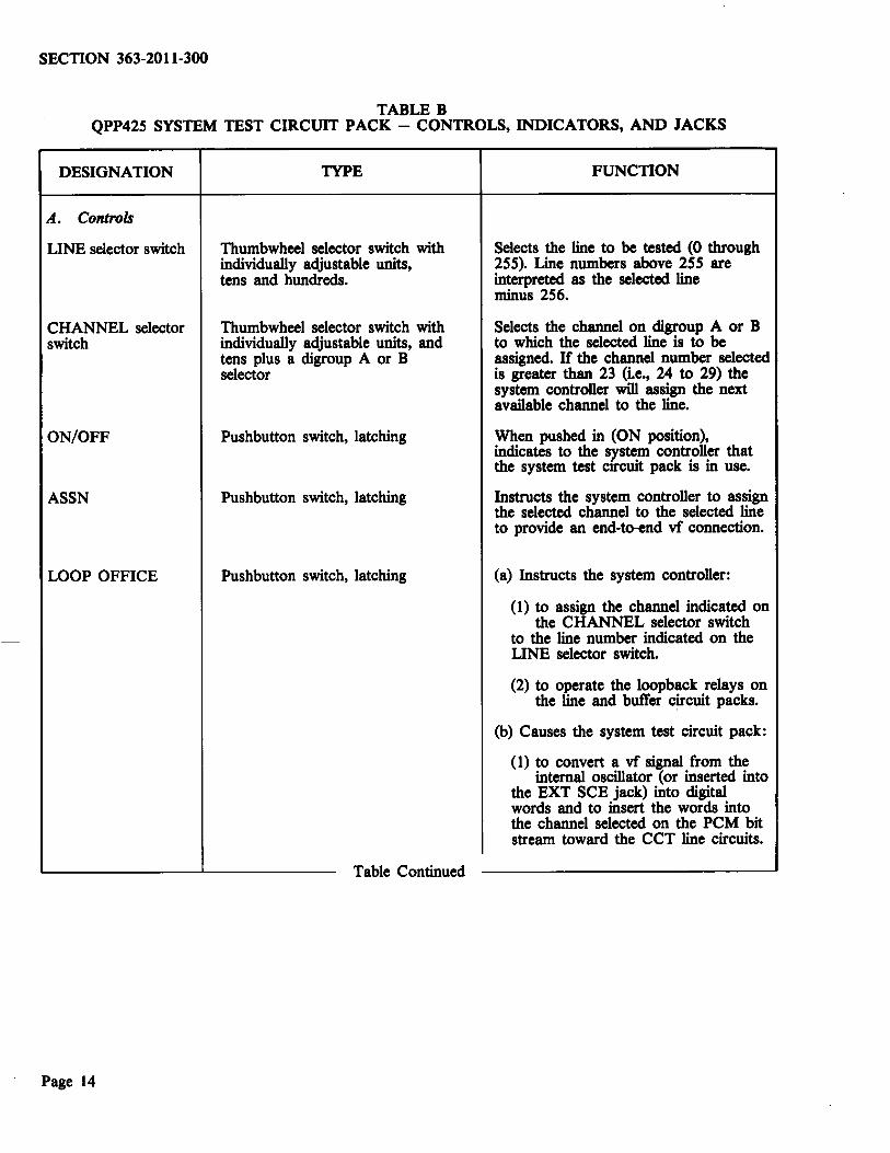
TABLE B QPP425 SYSTEM TEST CIRCUIT PACK- CONTROLS, INDICATORS, AND JACKS
DESIGNATION TYPE FUNCTION
A. Controls
LINE selector switch Thumbwheel selector switch with Selects the line to be tested (0 through individually adjustable units, 255). Line numbers above 255 are tens and hundreds. interpreted as the selected line
minus 256.
CHANNEL selector Thumbwheel selector switch with Selects the channel on digroup A or B switch individually adjustable units, and to which the selected line is to be
tens plus a digroup A or B assigned. If the channel number selected selector is greater than 23 (i.e., 24 to 29) the
system controller will assign the next available channel to the line.
ON/OFF Pushbutton switch, latching When pushed in (ON position), indicates to the system controller that the system test etreuit pack is in use.
ASSN Pushbutton switch, latching Instructs the system controller to assign the selected channel to the selected line to provide an end-to-end vf connection.
LOOP OFFICE Pushbutton switch, latching (a) Instructs the system controller:
(1) to assign the channel indicated on the CHANNEL selector switch
to the line number indicated on the LINE selector switch.
(2) to operate the loopback relays on the line and buffer circuit packs.
(b) Causes the system test circuit pack:
( 1) to convert a vf signal from the internal oscillator (or inserted into
the EXT SCE jack) into digital words and to insert the words into the channel selected on the PCM bit stream toward the CCT line circuits.
Table Continued
Page 14
SECTION 363-2011-300
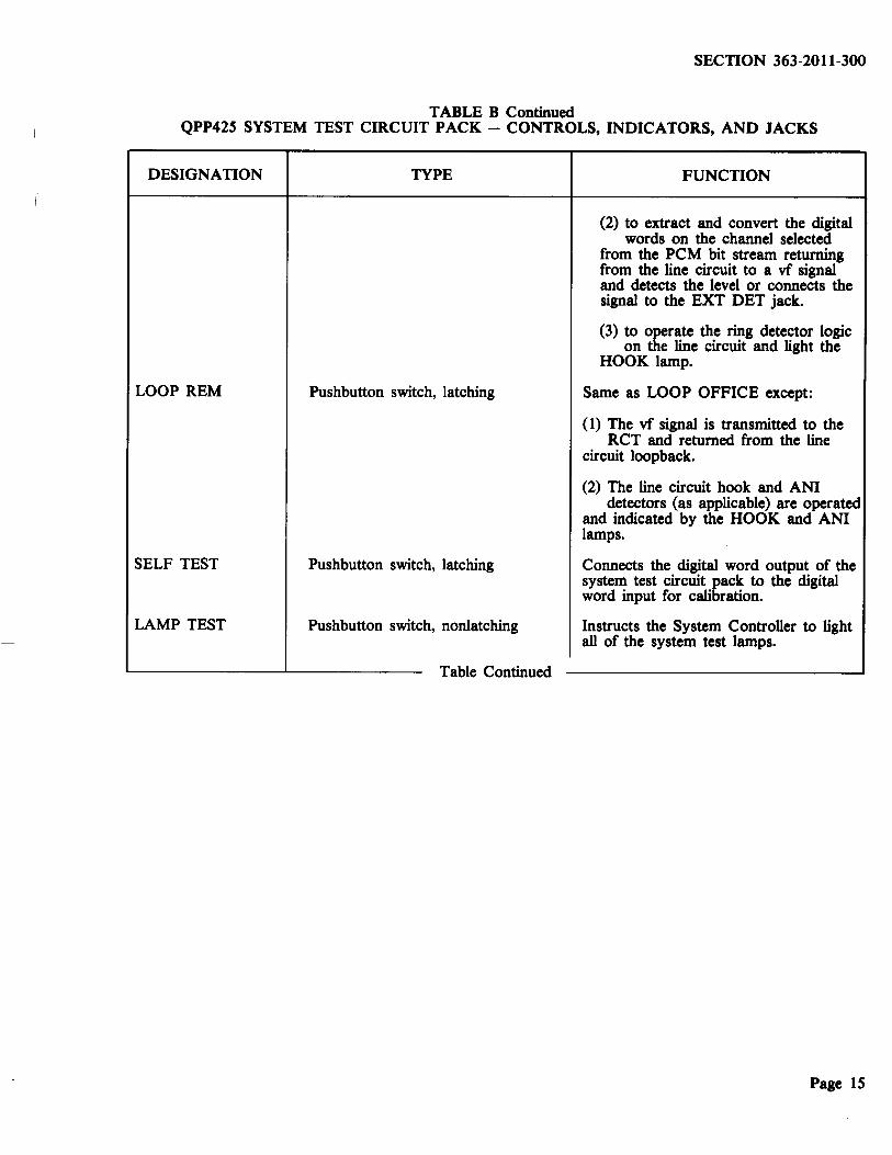
TABLE B Continued QPP425 SYSTEM TEST CIRCUIT PACK- CONTROLS, INDICATORS, AND JACKS
DESIGNATION TYPE FUNCTION
(2) to extract and convert the digital words on the channel selected
from the PCM bit stream returning from the line circuit to a vf signal and detects the level or connects the signal to the EXT DET jack.
(3) to rate the ring detector logic on e line circuit and light the
HOOK lamp.
LOOP REM Pushbutton switch, latching Same as LOOP OFFICE except:
(1) The vf signal is transmitted to the RCT and returned from the line
circuit loopback.
(2) The line circuit hook and ANI detectors (as applicable) are operated
and indicated by the HOOK and ANI lamps.
SELF TEST Pushbutton switch, latching Connects the digital word output of the system test circuit pack to the digital word input for calibration.
LAMP TEST Pushbutton switch, nonlatching Instructs the System Controller to light all of the system test lamps.
Table Continued
Page 15
SECTION 363-2011-300
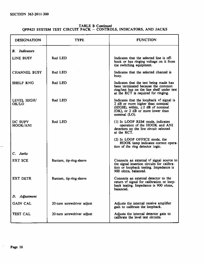
TABLE B Continued QPP42S SYSTEM TEST CIRCUIT PACK - CONTROLS, INDICATORS, AND JACKS
DESIGNATION TYPE FUNCTION
B. Indicators
LINE BUSY Red LED Indicates that the selected line is otT-hook or has ringing voltage on it from the switching equipment.
CHANNEL BUSY Red LED Indicates that the selected channel is busy.
SHELF RNG Red LED Indicates that the test being made has been terminated because the common . ring/test bus on the line shelf under test at the RCT is required for ringing.
LEVEL HIGH/ Red LED Indicates that the loopback vf signal is OK/LO 2 dB or more higher than nominal
(HIGH), within, ± 2 dB of nominal (OK), or 2 dB or more lower than nominal (LO).
DC SUPV Red LED (1) In LOOP REM mode, indicates HOOK/ANI operation of the HOOK and ANI
detectors on the line circuit selected at the RCT.
(2) In LOOP OFFICE mode, the HOOK lamp indicates correct opera-
tion of the ring detector logic.
c. Jacks
EXT SCE Bantam, tip-ring-sleeve Connects an external vf signal source to the signal insertion circuits for calibra-tion or loopback testing. Impedance is 900 ohms, balanced.
EXT DETR Bantam, tip-ring-sleeve Connects an external detector to the return vf signal for calibration or loop-back testing. Impedance is 900 ohms, balanced.
D. A4iustment
GAIN CAL 20-turn screwdriver adjust Adjusts the internal receive amplifier gain to calibrate the loopback.
TEST CAL 20-turn screwdriver adjust AdJusts the internal detector gain to calibrate the level test circuits.
Page 16

SECTION 363-2011-300
TABLE C QPP424 LINE TEST-OFFICE- CONTROLS AND INDICATORS
DESIGNATION TYPE FUNCTION
A. Controls
ON/OFF Pushbutton switch When pushed in (ON position), it indicates to the system controller that the Line Test circuits are in use.
AUTO/SEL Pushbutton switch, latching When left out (AUTO position), it causes the QPP423 line test remote circuit pack to measure ac volts, FEMF (DC) resistance, and capacitance for the selected line when the START/STOP button is pressed. When pushed in (SEL position), it causes test selected by the VOLTS ac, FEMF de, RES, CAP buttons to be repeated, and the display updated at each repetition. The test sequence is started by pressing the START/STOP button and updated continuously for 1 minute.
(See Note.)
AC VOLTS, Pushbutton switch, latching When pushed in, selects the test to be FEMF (DC), repeated (AUTO/SEL switch in SEL RES, Interlocked so that only one position) and results to be displayed. CAP can be selected at any one time
START/STOP Pushbutton switch, momentary Starts and stops testing as the button is pressed.
Table Continued
Page 17

SECTION 363-2011-300
TABLE C Continued QPP424 LINE TEST-OFFICE- CONTROLS AND INDICATORS
DESIGNATION
B. Indicators
TIP-RING TIP-GRD RING-GRD
V AC V DC KOHM J.LF
>RANGE OVLD
CAL CHK FAILED
HALTED
TESTING
TYPE
3 digit and sign, Red LED
Red LED
Red LED
Red LED
Red LED
Red LED
FUNCTION
Displays the results of the selected test from tip-to-ring, tip-to-ground and ringto-ground.
Indicates the test parameters being displayed when a test selection button is depressed.
Indicates that the value being measured is outside the measurement range of the line test remote circuit pack, or that the results of the test selected are not meaningful because of interference from a previous value (e.g., de on pair >9 V because of battery crossed to pair being measured makes resistance measurements invalid so the >RANGE/ OVLD indicator lights).
Indicates that the line test remote circuit pack has failed the self test calibration check and should be replaced.
Indicates that testing has stopped because:
( 1) another line on the shelf is being rung,
(2) START/STOP control button has been pressed.
Indicates that the tests are being carried out.
Note: In the auto run mode, results of resistance and capacitance measurements are compensated for the effects of FEMF (de). In the selective mode, this is not so and changes in de voltage on the pair since the preceding auto-run will give errors in results displayed.
Page 18

SECTION 363-2011-300
TABLED QPP450 TEST CONTROL CIRCUIT PACK- CONTROLS AND INDICATORS
DESIGNATION
A. Controls
LINE selector
CHANNEL selector
ON/OFF
ASGN
LOOP OFFICE
TYPE
Thumbwheel selector switch with individually adjustable units, tens and hundreds
Thumbwheel selector switch with individually adjustable units and tens, plus a digroup A or B selector
Pushbutton switch, latching
Pushbutton switch latching
Pushbutton switch, nonlatching
Table Continued
FUNCTION
Selects the line to be tested (0 through 255). Line numbers above 255 are interpreted by the system controller as the selected number minus 256.
Selects the channel or digroup A or B to which the selected line is to be assigned. If the selected channel number is greater than 23, the system controller assigns the next available channel to the line.
When pushed in (ON), indicates to the system controller that the circuit pack is enabled; an automatic 1-second lamp test is made when the switch is frrst turned ON.
Instructs the system controller to assign the selected channel to the selected line to provide an end-to-end vf connection; instructs the system controller to take-down a permanent-signal-release condition; instructs the system controller to take down a local link connection if the selected line is on a local link.
(a) Instructs the system controller:
(1) to assign the channel indicated on the CHANNEL selector to the
line indicated on the LINE selector,
(2) to operate the loopback relays on the line and buffer circuit packs.
(3) to operate the ring detector logic on the line circuit and light the
RING lamp.
(b) Causes the QPP450, as controlled by the system controller:
(1) to insert vf signal digital words into the selected channel on the
PCM bit stream toward the CCT line circuits,
Page 19

SECTION 363-2011-300
TABLE D Continued QPP450 TEST CONTROL CIRCUIT PACK- CONTROLS AND INDICATORS
DESIGNATION TYPE FUNCTION
{2) to extract the digital words from the selected channel of the PCM
bit stream returning from the line circuit, and to digitally detect the level.
LOOP REMOTE Pushbutton switch, nonlatching Same as LOOP OFFICE except:
(a) The vf signal is transmitted to the RCT and returned from the line
circuit loopback.
(b) The line circuit hook and ANI detectors (as applicable) are oper-
ated and indicated by the HOOK and ANI lamps.
SELF TEST Pushbutton switch, nonlatching Connects the digital word output of the QPP450 to the digital word input, for calibration.
P SIG RLS Pushbutton switch, nonlatching Instructs the system controller to set up a permanent signal release condition on the selected line if the line is busy.
B. Indicators
LOC LNK Red LED Indicates that the selected line is set up in a local link at the RCT.
UNE BUSY Red LED Indicates that the selected line is off-hook or has ringing voltage on it from the switching machine.
P SIG RLS Red LED Indicates a permanent signal release condition on the selected line.
CHANNEL BUSY Red LED Indicates that the selected channel is busy.
SHELF RNG Red LED Indicates that the test has been termi-nated because the common ring/test bus on the line shelf under test at the RCT is required for ringing.
Table Continued
Page 20

SECTION 363-2011-300
TABLE D Continued QPP450 TEST CONTROL CIRCUIT PACK - CONTROLS AND INDICATORS
DESIGNATION TYPE FUNCTION
LEVEL HIGH/ Red LED (3) Indicates that the loopback vf signal is LO/OK 2 dB or more higher than nominal
(HIGH), within ±2 dB of nominal (OK), or 2 dB or more lower than nominal (LO).
DC SUPV Red LED (3) (a) In LOOP REM mode, the HOOK HOOK/ ANI/RING and ANI indicators indicate opera-
tion ·of the hook and ANI detectors on the line circuit selected at the RCT.
(b) In LOOP OFFICE mode, the RING lamp indicates correct operation of
the ring detector logic.
TABLE E QPP448 TEST ACCESS OFFICE- CONTROL, INDICATORS, JACKS
QPP447 TEST ACCESS REMOTE- INDICATORS
DESIGNATION CIRCUIT TYPE FUNCTION PACK
A. Controls Note: There are no controls on the QPP447.
ON/OFF QPP448 Pushbutton switch, When pushed in (ON), indicates only latching to the system controller the
QPP448 switches are enabled; an automatic 1-second lamp test is made when the switch is first turned ON.
MTCE/MAN TST QPP448 Pushbutton switch, When pushed in, instructs the only latching system controller to attempt a
manual bypass on the selected line; this action connects subscriber loop at RCT at MANUAL TEST jacks through a test pair, and informs associ-ated CCT that the test pair is busy.
SPARE LINE QPP448 Pushbutton switch, When pushed in (ON), instructs only latching the system controller to attemp
a man~are operation on the sel line; this action reroutes the line over a desig-nated spare line of the DMS-1.
Table Continued
Page 21
SECTION 363-2011-300
TABLE E Continued QPP448 TEST ACCESS OFFICE - CONTROL, INDICATORS, JACKS
QPP447 TEST ACCESS REMOTE- INDICATORS
DESIGNATION CIRCUIT TYPE FUNCTION PACK
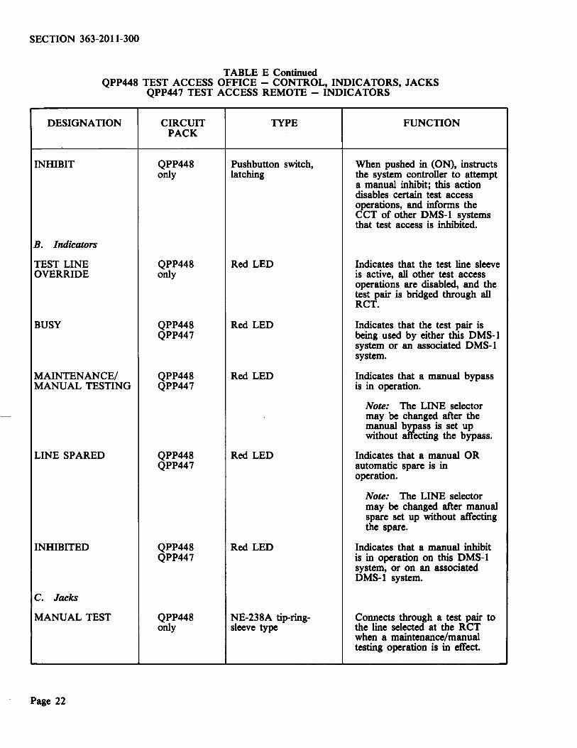
INHIBIT QPP448 Pushbutton switch, When pushed in (ON), instructs only latching the system controller to attempt
a manual inhibit; this action disables certain test access operations, and informs the CCT of other DMS-1 systems that test access is inhibited.
B. Indicators
TEST LINE QPP448 Red LED Indicates that the test line sleeve OVERRIDE only is active, all other test access
operations are disabled, and the test pair is bridged through all RCT.
BUSY QPP448 Red LED Indicates that the test pair is QPP447 being used by either this DMS-1
system or an associated DMS-1 system.
MAINTENANCE/ QPP448 Red LED Indicates that a manual bypass MANUAL TESTING QPP447 is in operation.
Note: The LINE selector may be changed after the manual ~ass is set up without ecting the bypass.
LINE SPARED QPP448 Red LED Indicates that a manual OR QPP447 automatic spare is in
operation.
Note: The LINE selector may be changed after manual spare set up without affecting the spare.
INHIBITED QPP448 Red LED Indicates that a manual inhibit QPP447 is in operation on this DMS-1
system, or on an associated DMS-1 system.
c. Jacks
MANUAL TEST QPP448 NE-238A tip-ring- Connects through a test pair to only sleeve type the line selected at the RCT
when a maintenance/manual testing operation is in effect.
Page 22

SECTION 363-2011-300
CHART 8 QPP425 SYSTEM TEST CIRCUIT PACK CALIBRATION AND TESTS
This chart describes the procedures to:
(a) calibrate the level detector in the QPP425 circuit pack for automatic loopback testing,
(b) check the level of the loopback signal at the 2-wire connection of a selected line circuit using the internal oscillator and detector of the QPP425 circuit pack,
(c) test level, frequency response, noise, and distortion using the QPP425 circuit pack in the LOOP mode,
(d) assign a channel to a line for end-to-end vftests by using the assign function of the QPP425 circuit pack.
TEST EQUIPMENT:
Telephone Test Oscillator, Hewlett-Packard 236A, or equivalent
Transmission and Noise Measuring Set (TNMS), Hewlett-Packard 3555B, or equivalent
2 Patch Cords, Bantam (tip-ring-sleeve), Switchcraft TT128 or NEP3Q3.
STEP PROCEDURE
A. Self Test
Note: This test checks the calibration of the internal level testing circuits.
Depress the ON button.
2 Press and hold the LAMP TEST button.
Requirement: All indicators on the QPP425 light.
3 Release the LAMP TEST button.
4 Depress the SELF TEST button.
Requirement: The LEVEL OK lamp lights.
If the requirement is not met, continue with Step 5.
If the requirement is met, go to Test C, Step 25.
Chart Continued
Page 23

SECTION 363-2011-300
CHART 8 Continued QPP42S SYSTEM TEST CIRCUIT PACK CALIBRATION AND TESTS
STEP PROCEDURE
B. Calibration
Note: The calibration procedure sets the HI and LO indicator thresholds about 2 dBm above or below the nominal loopback level.
S Connect the test equipment as shown in Fig. S, with the switch settings as shown.
6 Measure and record the reading on the TNMS.
Requirement: 0± 1 dBm.
7 Adjust the oscillator output until the TNMS reads 0±0.1 dBm.
8 On the QPP425, set the LINE selector to an idle or unused line number, and the CHANNEL selector to 829 (to prevent service from being affected accidently).
9 Connect the test equipment to the QPP425 circuit pack as shown in Fig. 6. Do not change the switch settings on the test equipment.
10 Tum the GAIN CAL control until the meter reading is -0.6±0.1 dBm.
11 Disconnect the oscillator and TNMS from the EXT SCE and EXT DETR jacks.
12 Tum the TEST CAL control until the OK and LO indicators light with equal brilliance.
13 Tum the screwdriver GAIN CAL control until the OK and HIGH indicators light with equal brilliance.
14 Reconnect the oscillator and the TNMS. (Do not change the test set switch settings from those shown in Fig. 5.)
Requirement: The reading on the TNMS must be +0.6±0.3 dBm.
If the requirement is not met, replace the QPP425, and repeat the tests from Step 1.
15 Tum the screwdriver GAIN CAL control until the TNMS meter reading is 0±0.1 dBm.
16 Disconnect the oscillator and the TNMS from the EXT SCE and EXT DETR jack.
Requirement: The OK indicator must light.
If the HIGH or W indicator lights, the calibration procedure was not carried out correctly. Repeat Steps 5 through 15 until the requirement has been met.
17 Release the SELF TEST switch.
18 Release the ON/OFF switch.
Chart Continued
Page 24

SECTION 363-2011-300
CQ CEN
OUTPUT
SWITCH SETTINGS:
FREQUENCY : 800Hz IMPEDANCE : 900 OHMS BALANCED LEVEL : OdBm
PATCH CORD
f) TNMS
SWITCH SETTINGS:
IMPEDANCE : 900 OHMS BALANCED TERMINATING
LEVEL : OdBm
Fig. 5 - Test Equipment Calibration
(Q GEN
SYSTEM TEST liN£
CHANNEl
"' Qi'Poi.HA
363-028
Fig. 6 - System Test Calibration
Q TNMS
Input 0 600 ] IN ~900
Page 25

SECTION 363-2011-300
CHART 8 Continued QPP425 SYSTEM TEST CIRCUIT PACK CALIBRATION AND TESTS
STEP PROCEDURE
C. VF Loopback- Automatic Level Test
This procedure checks the level of the signal at the 2-wire connection of a selected line using the QPP425 circuit pack.
Caution: To pre11ent service interruptions, ensure that all the pushbutton 6Witches on the QPP425 circuit pack are in the out position btfore carrying out the following steps.
18 Switch the CHANNEL selector switch to the desired channel, or to an indication between 24 and 29 if the channel to be used does not matter.
19 Switch the LINE selector switch to the line number to be tested.
20 Depress the ON/OFF switch until it latches.
Requirement: The BUSY and SHELF RNG indicators must not light.
Note 1: If the CHANNEL BUSY indicator is on:
(a) Switch the ON/OFF switch on the QPP425 circuit pack to OFF.
(b) Select another channel.
(c) Switch the ON/OFF switch on the QPP425 circuit pack to ON.
Note 2: If the LINE BUSY indicator is on, wait until it goes out. The busy condition can be overridden for maintenance operation by using Step 22.
Note 3: If the SHELF RNG indicator is on, wait until it goes out before proceeding.
Caution: The next step interrupts service on the line under test. Wait until the Une is idle.
21 On the QPP425A, press the LOOP OFFICE button, until it latches; on the QPP425B or QPP450, press and hold the button on the front panel.
Page 26
Requirement: The OK and HOOK indicators must light.
If the requirement is not met either the QPP425 or the line is faulty. Refer to 363-2011-500 Part 4 to locate and correct the fault.
Note: If ringing is received for another line on the same line shelf, the test is terminated automatically on the line under test. When the SHELF RNG indicator goes out, the test will be automatically reinitiated.
Chart Continued

SECTION 363-2011-300
CHART 8 Continued QPP425 SYSTEM TEST CIRCUIT PACK CALIBRATION AND TESTS
STEP PROCEDURE
22 Release the LOOP OFFICE button.
Requirement: The OK and HOOK indicators must go out.
23 Depress the LOOP REM button.
Requirement 1: The OK and HOOK indicators must light.
Requirement 2: H the line selected is connected to a universal line circuit pack, the ANI indicator must light.
24 Release the LOOP REM button.
Requirement: The OK, HOOK, and ANI indicators (if applicable) must go out.
25 Release the ON/OFF button.
D. VF Loopback- External Test Equipment
26 Connect the test equipment to the QPP425 circuit pack as shown in Fig. 6.
Note: The loopback transmission path through the QPP425 circuit pack is intended only for use in isolating noise or distortion faults to either the CCT or the RCT.
E. Assign - End-to-End VF Connection
This procedure assigns a channel to a line for an end-to-end vf connection for monitoring and testing by using the ASGN function of the system test circuit pack.
Caution: To prevent service interruption, ensure aU the pushbutton switehes are in the out position bqore carrying out the following steps.
27 Perform Steps 18 through 20 of this chart.
28 Depress the ASGN button.
Note: The optional jackfield on each of the line shelves provides access to the line under test. H the jackfield is not available, access to the line can be obtained through the Distribution Frame (OF).
29 After the tests have been completed, release the ASGN button.
30 Release the ON/OFF button.
Page 27

SECTION 363-2011-300
CHART 9 QPP424 LINE TEST - OFFICE CIRCUIT PACK OPERATION
This chart describes the procedures for automatic testing of all parameters or repetitive testing of a single parameter on a subscriber line under test.
TEST EQUIPMENT: None required.
STEP PROCEDURE
A. Lamp Test and Calibration Check
1 Select the number of the line to be tested on the LINE selector switch on the QPP425 system test circuit pack.
Note: Ignore the setting on the channel-selector switch. The system controller selects an unassigned channel for subscriber line testing.
Caution: Service is interrupted when the testing button is pressed while the line BUSY indicator lamp is lit.
2 Depress the ON/OFF (testing) button on the QPP424line test office circuit pack until it latches.
Requirement 1: All indicators must light and the three displays indicate -.8.8.8 for 1 second.
Requirement 2: The line test-remote then performs a calibration check test. This is indicated by dashes (----) on the displays and the TESTING lamp on the QPP424.
Requirement 3: Within 4 seconds, the TESTING indicator goes out, but the dashes remain on.
If the requirements are not met, refer to 363-2011-500, Table F for fault location.
B. Automatic Test Sequence
3 If only one test is to be performed, go to Step 6.
Page 28
If all tests are required, (ac V, FEMF de, Resistance and Capacitance) depress the CAP button until it latches, then press the START/STOP button.
Requirement 1: The dashes on the displays remain on until the first test result is available.
Requirement 2: The V ac, V de, k ohm, and ~tF indicators light sequentially, and the test results are displayed, after each test has been completed.
Requirement 3: The TESTING indicator then goes out.
Note 1: The CAP button must be pressed for the capacitance measurement to be displayed. If any other test selection button is pressed, the display reverts to that measurement after resistance has been displayed.
Note 2: If the ratio of resistance measurements is greater than 10 to 1 (example: T-R = 10k, T-G = R-G ~lOOk), only the lowest value is displayed. The other displays are blank.
Note 3: The > RANGE/OVLD indicator may light briefly if the resistance measurement is greater than 7 50k ohms.
Chart Continued

SECTION 363-2011-300
CHART 9 Continued QPP424 LINE TEST- OFFICE CIRCUIT PACK OPERATION
STEP PROCEDURE
If the testing is interrupted or if test requirements are not met, check the status of other indicators on both the QPP424 and the QPP425. The testing is interrupted under the following conditions:
(a) Testing stops, if more than 150 V ac or 60 V de is present on the pair under test. In which case:
(1) the > RANGE/OVLD indicator must light,
(2) the display must indicate 150 or 60 V respectively.
(b) Testing stops, if the quantity measured in the previous test affects the accuracy of the following measurement, e.g.:
ac voltage > 7 5 V, de voltage > 9 V, resistance < lOk ohms
In which case:
(I) the >RANGE/OLVD indicator must light,
(2) the display for the affected test result must be blank.
(c) Ringing received at the CCT on a line on the shelf under test (other than the line under test) causes testing to be stopped until the ringing stops or 5 minutes have elapsed. In this case:
(1) the HALTED indicator on QPP424 must light,
(2) the SHELF RINGING indicator on QPP425 must light.
(d) Testing can be stopped by pressing the START/STOP button. In which case:
(I) the HALTED indicator on the QPP424 must light.
The test continues, if the START/STOP button is pressed again.
4 To select the measured quantity to be displayed, depress the ac VOLTS, FEMF (de), RES, or CAP button until it latches.
Requirement 1: The related V ac, V de, k ohms, or ~J.F indicator must light.
Requirement 2: The measured value must be displayed.
Note: No measured value appears on the tip-ring display, if AC VOLTS or FEMF DC are selected, since only the tip-to-ground and ring-to-ground values are measured.
5 Depress the ON/OFF button until it unlatches.
Requirement: All indicators must go out.
Chart Continued
Page 29

SECTION 363-2011-300
CHART 9 Continued QPP424 LINE TEST- OFFICE CIRCUIT PACK OPERATION
STEP PROCEDURE
C. Selective Tests
Note: A complete automatic test sequence is carried out when the QPP424 ftrst measures a line and every 5 minutes thereafter to update the test results that may affect the parameter being measured.
6 Depress the ON/OFF button until it latches.
Requirement: Same as in Step 2.
7 Depress the AUTO/SEL button until it latches.
8 Depress the button for the test to be performed.
Requirement 1: The associated indicator must light.
9 Press the START/STOP button.
Requirement 1: The TESTING lamp must light.
Requirement 2: An automatic test sequence is performed (see Note above Step 6).
Requirement 3: The display blinks as the selected test results are updated from each successive test.
Note: The test is stopped after 1 minute. The test can be continued without repeating the auto-test sequence, if the START/STOP button is pressed within 4 minutes.
If the requirements are not met, refer to Step 3 for conditions which cause testing to be stopped.
10 Depress the ON/OFF button until it unlatches.
Requirement: All indicators go out.
Page 30

SECTION 363-2011-300
CHART 10 QPP450 TEST CONTROL CIRCUIT PACK TESTS
STEP PROCEDURE
A. Self Test
Note: This test checks the operation of the internal level testing circuits.
Depress the ON button, and observe the automatic 1-second lamp test.
Requirement: All indicators on the QPP450 light for about 1 second.
2 Depress the SELF TEST button.
Requirement: LEVEL OK lamp lights.
If the requirement is not met, replace the QPP450.
B. VF Loopback - Automtltic Level Test
This procedure checks the signal level at the 2-wire connection of a selected line using the QPP450 circuit pack.
Caution: To prevent service interruptions, ensure that all pushbuttons on the QPP450 are in the out position btfore starting Step 3.
3 Set the CHANNEL selector to the desired channel or to an indication between 24 and 29, if the channel to be used does not matter.
4 Set the LINE selector to the number of the line to be tested.
5 Depress the ON/OFF switch until it latches in (ON).
Requirement: The BUSY and SHELF RNG indicators must not light.
Note 1: If the CHANNEL BUSY indicator is on, select another channel.
Note 2: A busy channel is indicated on both digroups A and B for any line on the line shelf selected (see 363-2011-450 for details).
Note 3: If the LINE BUSY indicator is on, wait until it goes out. The busy condition can be overridden for a maintenance operation by using Step 7.
Note 4: If the SHELF RNG indicator is on, wait until it goes out.
Caution: The next step interrupts service on the Une under test. Wait until the Une is idle.
Chart Continued
Page 31

SECTION 363-2011-300
CHART 10 Continued QPP450 TEST CONTROL CIRCUIT PACK TESTS
STEP PROCEDURE
6 Press and hold the LOOP OFFICE button.
Requirement: The OK and RING indicators must light.
If this requirement is not met, either the QPP450 or the line is faulty. Refer to 363-2011-500 to locate and correct the fault.
Note: If ringing is received during the test for another line on the same line shelf, the test is terminated automatically on the line under test. When the SHELF RNG indicator goes out, the test is automatically reinitiated.
7 Release the LOOP OFFICE button.
Requirement: The OK and RING indicators must go out.
8 Press and hold the LOOP REM button.
Requirement 1: The OK and HOOK indicators must light.
Requirement 2: If the selected line is connected to a universal line circuit pack, the ANI indicator must light.
9 Release the LOOP REM button.
Requirement: The OK, HOOK, and ANI indicators must go out.
10 Release the ON/OFF button.
C. Assign - End-To-End Connection -Local Link Takedown
This procedure assigns a channel to a line to provide an end-to-end vf connection for monitoring and testing by using the ASGN function of the QPP450.
Caution: To prevent service interruptions, be sure all pushbutton switches are in the OUT position bPJore starting Step 11.
11 Perform Steps 3, 4, and 5 of this chart.
Chart Continued
Page 32
SECTION 363-2011-300
CHART 10 Continued QPP450 TEST CONTROL CIRCUIT PACK TESTS
STEP PROCEDURE
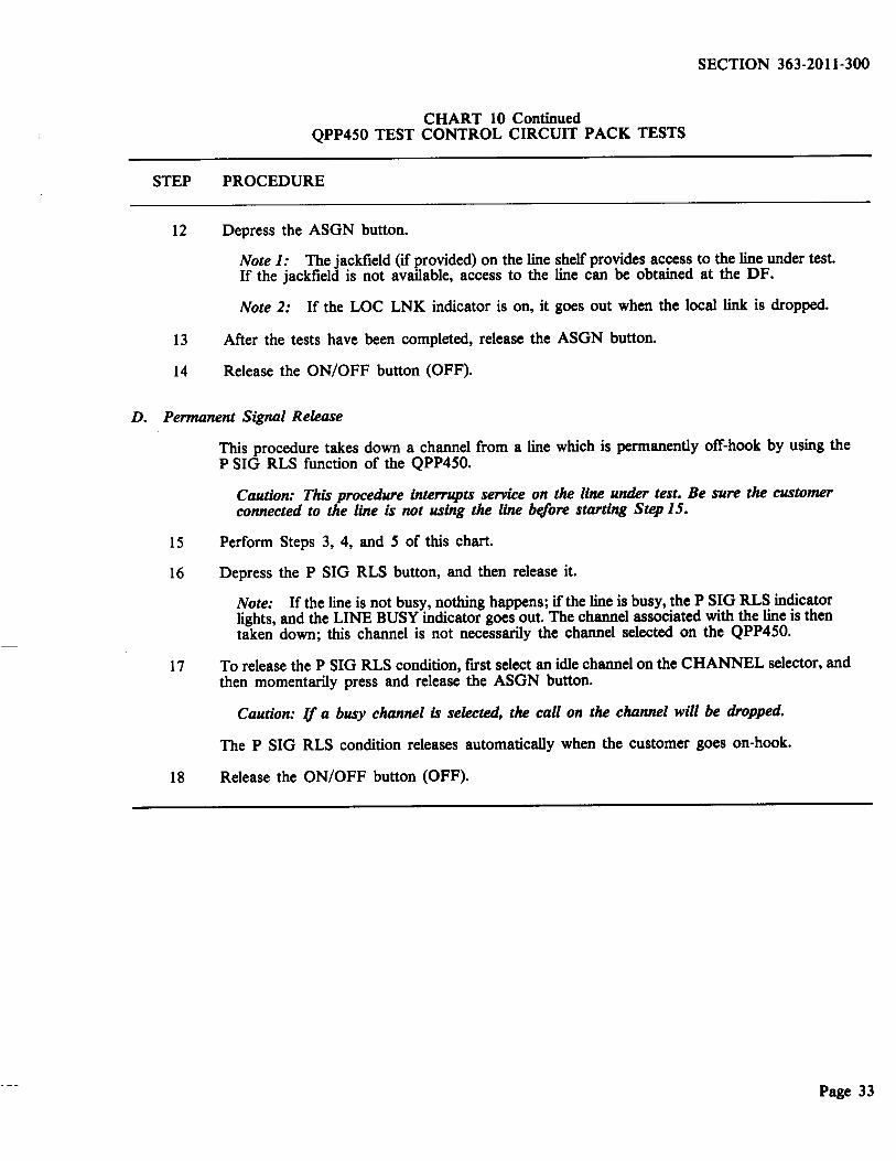
12 Depress the ASGN button.
Note 1: The jackfield (if provided) on the line shelf provides access to the line under test. If the jackfield is not available, access to the line can be obtained at the DF.
Note 2: If the LOC LNK indicator is on, it goes out when the local link is dropped.
13 Mter the tests have been completed, release the ASGN button.
14 Release the ON/OFF button (OFF).
D. Permanent Signal Release
This procedure takes down a channel from a line which is permanently off-hook by using the P SIG RLS function of the QPP450.
Caution: This procedure interrupts service on the line under test. Be sure the customer connected to the line is not using the line bf(ore starting Step 15.
15 Perform Steps 3, 4, and 5 of this chart.
16 Depress the P SIG RLS button, and then release it.
Note: If the line is not busy, nothing happens; if the line is busy, the P SIG RLS indicator lights, and the LINE BUSY indicator goes out. The channel associated with the line is then taken down; this channel is not necessarily the channel selected on the QPP450.
17 To release the P SIG RLS condition, ftrst select an idle channel on the CHANNEL selector, and then momentarily press and release the ASGN button.
Caution: q a busy channel is selected, the caU on the channel will be dropped.
The P SIG RLS condition releases automatically when the customer goes on-hook.
18 Release the ON/OFF button (OFF).
Page 33
SECTION 363-2011-300
CHART 11 QPP448 TEST ACCESS CIRCUIT PACK OPERATION
STEP PROCEDURE
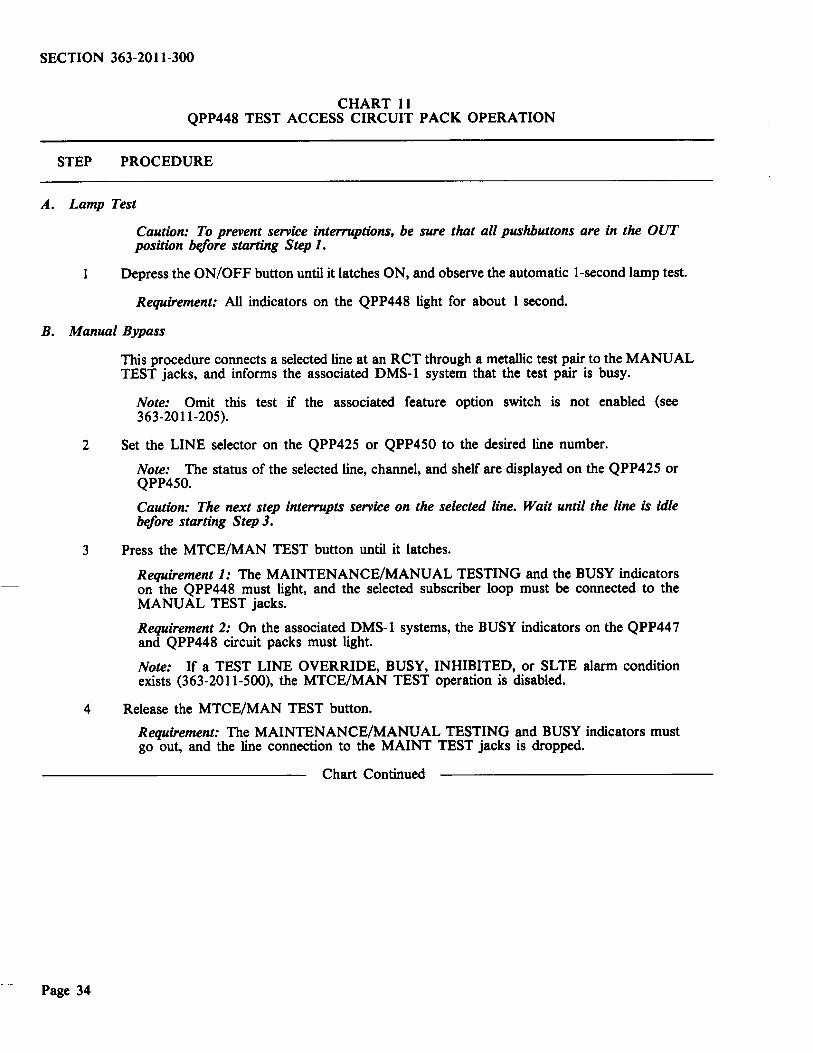
A. Lamp Test
Caution: To prevent service interruptions, be sure that all pushbuttons are in the OUT position bt:fore starting Step 1.
1 Depress the ON/OFF button until it latches ON, and observe the automatic 1-second lamp test.
Requirement: All indicators on the QPP448 light for about l second.
B. Manual Bypass
This procedure connects a selected line at an RCT through a metallic test pair to the MANUAL TEST jacks, and informs the associated DMS-1 system that the test pair is busy.
Note: Omit this test if the associated feature option switch is not enabled (see 363-2011-205).
2 Set the LINE selector on the QPP425 or QPP450 to the desired line number.
Note: The status of the selected line, channel, and shelf are displayed on the QPP425 or QPP450.
Caution: The next step interrupts service on the selected line. Wait until the line is idle bt:fore starting Step 3.
3 Press the MTCE/MAN TEST button until it latches.
Requirement 1: The MAINTENANCE/MANUAL TESTING and the BUSY indicators on the QPP448 must light, and the selected subscriber loop must be connected to the MANUAL TEST jacks.
Requirement 2: On the associated DMS-1 systems, the BUSY indicators on the QPP447 and QPP448 circuit packs must light.
Note: If a TEST LINE OVERRIDE, BUSY, INHIBITED, or SLTE alarm condition exists (363-2011-500), the MTCE/MAN TEST operation is disabled.
4 Release the MTCE/MAN TEST button.
Page 34
Requirement: The MAINTENANCE/MANUAL TESTING and BUSY indicators must go out, and the line connection to the MAINT TEST jacks is dropped.
Chart Continued

SECTION 363-2011-300
CHART II Continued QPP448 TEST ACCESS CIRCUIT PACK OPERATION
STEP PROCEDURE
C. Manual Sparing
This procedure reroutes a selected line on a designated DMS-1 spare line (designated by option switch settings; see 363-2011-205) which is equipped with a line card that is compatible with the line being rerouted.
Note: Omit this test, if the associated feature option switch is not enabled (see 363-2011-205).
5 Set the LINE selector on the QPP425 or QPP450 to the desired line number.
Note: The status of the selected line, and the associated channel and line shelf are displayed on the QPP425 or QPP450.
Caution: Step 6 interrupts service on the selected line. Wait until the line is idle IH:fore starting Step 6.
6 Press the SPARE LINE button until it latches.
Requirement: The LINE SPARED indicator must light, and the selected line must be rerouted on a designated spare line with a compatible type of line card.
Note: The SPARE LINE operation is disabled by any of the following:
• feature option switch not enabled (363-2011-205),
e presence of a TEST LINE OVERRIDE or BUSY condition,
• selection of a designated spare line for the SPARE LINE operation,
• failure of the system controller to fmd a designated DMS-1 spare line with a compatible type of line card,
• presence of an SLTE alarm condition (see 363-2011-500).
7 Release the SPARE LINE button.
Requirement: The LINE SPARED indicator must go out, and the rerouted line must revert to normal operation.
Chart Continued
Page 35

SECTION 363-2011-300
CHART 11 Continued QPP448 TEST ACCESS CIRCUIT PACK OPERATION
STEP PROCEDURE
D. Manual Inhibit
This procedure disables certain test access operations and informs associated DMS-1 systems that test access is inhibited.
Note: Omit this test if the associated feature option switch is not enabled (363-2011-205).
8 Press the INHIBIT button until it latches.
Requirement:
• INHIBIT indicator must light.
• Manual bypass (Test B) does not operate.
• Manual sparing (Test C) does operate.
• The BUSY condition from an associated DMS-1 system disappears.
• The INHIBIT indicators on all associated DMS-1 systems must light.
Note: If a TEST OVERRIDE condition is in effect, the operation of this INHIBIT test is disabled.
9 Release the INHIBIT button.
Requirement: Unless an associated DMS-1 system is sending an INHIBIT indication:
(1) the INHIBIT indicator goes out, and
(2) any previous operations disabled by the INHIBIT operation are enabled again.
10 Release the ON/OFF switch on the QPP448 (OFF).
Page 36

S. ORDER WIRE
5.01 The order-wire and fault-locate shelf, when used with the LD-1 line in the DMS-1 system,
has the following functions:
• it can be used for calling from an apparatus case to either a CCT or an RCT, or
• it can be used for calling from an RCT to a CCT.
SECTION 363-2011-300
5.02 The operation of the order-wire section of the order-wire and fault-locate shelf is described
in the following charts:
Chart 12
Chart 13
Initiating a Call at an RCT
Initiating a Call from a Repeater Site
Chart 14 - Answering a Call at the CCT.
CHART 12 INITIATING A CALL AT AN RCT
This chart describes the procedure for connecting a headset to the order-wire circuit packs and for initiating a call.
STEP PROCEDURE
1 Connect the headset to the HEADSET jacks on the QPP303 telephone set circuit pack.
2 Patch the LINE jack on the QPP303 circuit pack to the ORDER-WIRE jack on the QPP302 span order-wire termination or QPP304 bridging circuit, using a bantam tip-ring-sleeve patch cord (e.g., Switchcraft TT128 or NEP3Q3).
3 Press the DIAL DISC button for 3 seconds to operate the office alarm system at the CCT location.
Note: The DIAL DISC button operates the office alarm system if the order-wire pair is less than 12 to 15 miles in length. If the CCT to RCT distance is greater than about 12 to 15 miles, prearrangements must be made to have someone connect to the CCT order-wire and establish oral communication.
Page 37

SECTION 363-2011-300
CHART 13 INITIATING A CALL FROM A REPEATER SITE
This chart describes the procedure to originate a call from a repeater site.
APPARATUS:
QSE4Bl or NE-1011 Q (-) handset.
STEP PROCEDURE
Unscrew protective cover over the order-wire terminations.
2 Set talk/monitor switch on the handset to monitor.
3 Connect the headset to the order-wire terminals.
4 Set talk/monitor switch on the handset to talk.
If the dial tone is present, dialing on the subscriber line is possible.
If dial tone is not present, the order-wire is in use.
Chart Continued
Page 38

STEP
5
SECTION 363-2011-300
CHART 13 Continued INITIATING A CALL FROM A REPEATER SITE
PROCEDURE
To disconnect dial tone, ground one of the order-wire terminals for about 3 seconds to any exposed metal on the apparatus case.
Requirement 1: Dial tone disappears. Talking with other locations is possible.
Requirement 2: DIAL DISC on the QPP302 or QPP304 lights, and a minor office alarm is initiated to signal office personnel.
CHART 14 ANSWERING A CALL AT THE CCT
This chart describes the procedure for connecting a headset to the order-wire circuit packs and for answering a service call.
STEP
1
2
PROCEDURE
When the office minor alarm operates for a service call on the order-wire, patch the LINE jack on the QPP303 telephone set circuit pack to the ORDER-WIRE jack on the QPP302 span order-wire termination circuit pack using a bantam tip-ring-sleeve patch cord.
Connect a headset to the HEADSET jacks on the telephone set pack, and establish communication.
Note: The office alarm is operated as long as the call originator presses on the DIAL DISC button at the calling site (see Chart 12).
Page 39

SECTION 363-2011-300
6. EMERGENCY POWER
6.01 In the event of a prolonged commercial power failure at an RCT cabinet, it may be necessary
to connect an emergency generator to sustain operation. The procedure is given in Chart 15.
CHART 15 CONNECTING AND REMOVING AN EMERGENCY GENERATOR AT AN RCT
STEP PROCEDURE
.A. Connecting the Emergency Generator Unit to the RCT
1 At the RCT cabinet, move the power transfer switch from NORMAL to OFF.
2 Turn the ac circuit breaker of the RCT cabinet rectifier to OFF.
3 Determine the output voltage connections in the rectifier by following the procedure in 363-2011-207 Chart 1, Steps 1 to 3; e.g., 120, 240, 208 V, etc.
4 Verify that the emergency generator provides the output determined at Step 3.
5 Remove the cover from the emergency power receptable on the RCT cabinet.
6 Verify that the emergency power receptable is compatible with the output plug on the emergency generator cable.
Note: If not compatible, an APJ3485-M7 Crouse-Hinds plug (30 amps) is supplied with the cabinet to permit adapting of the emergency generator output to the cabinet input.
7 Connect the emergency generator to the RCT cabinet.
8 Start the generator, and verify the output by monitoring the voltage at the power transfer switch inside the RCT cabinet.
9 Move the power transfer switch from OFF to EMERGENCY.
10 Turn the ac breaker of the RCT cabinet rectifier to ON, and verify that the AC ON LED is lit.
Note: The RCT is now operating in the emergency generator supply.
11 When the normal commercial supply has been restored proceed with the removal of the emergency power generator.
B. Removing the Emergency Generator Connection from the RCT Cabinet
12 Turn the ac breaker of the RCT cabinet rectifier to the OFF position.
13 Move the RCT cabinet power transfer switch from EMERGENCY to OFF.
14 Turn off the emergency power generator and disconnect it from the RCT cabinet.
15 Move the RCT cabinet power transfer switch from the OFF to the NORMAL position.
16 Turn the ac breaker of the RCT cabinet rectifier to ON, and ensure that the AC ON LED is lit.
Note: The RCT is now operating in the normal commercial power supply.
Page 40
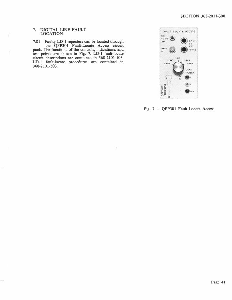
7. DIGITAL LINE FAULT LOCATION
7.01 Faulty LD-1 repeaters can be located through the QPP301 Fault-Locate Access circuit
pack. The functions of the controls, indications, and test points are shown in Fig. 7. LD-1 fault-locate circuit descriptions are contained in 368-2101-103. LD-1 fault-locate procedures are contained in 368-2101-503.
SECTION 363-2011-300
FAULT LOCATE ACCESS
HIGH
SIG OUf
lOW
POWfR
ON
- HIGH
OH
~ EAST 'l liNE
WEST
+HIGH
LI NE POWER
- 10 ~
~ . 'il •• ~~ oa:: ~ ~ I COM .:..o o.:...
Fig. 7 - QPP301 Fault-Locate Access
Page 41