northam eco lifestyle village da submission · the approval of the northam eco lifestyle village...
TRANSCRIPT

1
H&H Development Enterprises
December 2016
Northam Eco Lifestyle Village DA Submission

Contact
H&H Development Enterprises Pty LtdSuite 24, 25 Walters Drive, Osborne Park WA 6017
hhdevelopment.com.au
Mike HollettBusiness Development Director0427 493 [email protected]
Chris HarrisonSales & Operational Director0413 120 [email protected]

3
Contents1 Introduction Page 4
2 Subject Land Page 6
3 The Proposal Page 8
4 Planning Considerations Page 18
5 Engineering and Services Considerations Page 20
6 Sustainability - One Planet Living Accreditation Page 26
7 Implementation Page 28
8 Conclusion Page 29
9 Appendices Page 30
4
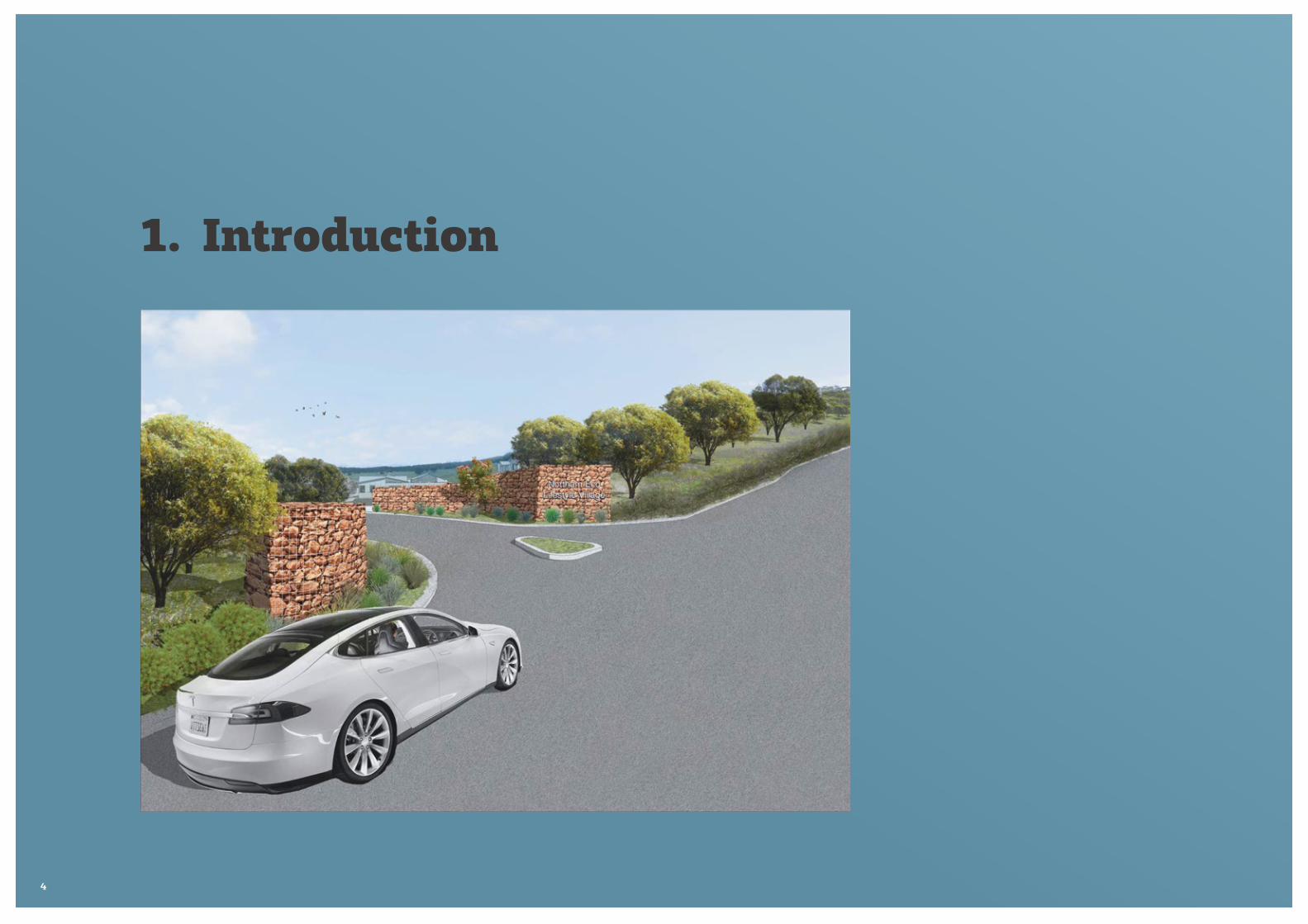
1. Introduction

5
Purpose of Application
Planning Approval is sought for a Lifestyle Village containing 250 dwellings on a portion of Lot 9000, Mt Ommaney Road, Northam.
H&H Development Enterprises Pty Ltd (HHDE) as development managers for Quickfire Property Trust No 1 the owners of Lot 9000 propose to develop, build and manage the Northam Eco Lifestyle Village providing a unique country community lifestyle for over 45s.
The development is based on a 60 year land lease model with innovative quality designed modular housing that, being relocatable, lightly touch the land respecting the land form and creating a community that interacts sustainably in the emerging shared economy.
This Proposal in the Regional Context
The site known as Lot 9000 is located on the planned western urban front of Northam. Northam is the regional centre for the Wheatbelt Region which is located approximately 96 km east of Perth and is a nominated Super Town under the State Government’s Regional Centres Development Plan. The Super Towns program was established to assist diversify and decentralise Western Australia’s projected population growth by providing attractive alternate residential locations outside of Metropolitan Perth.
The development of a Lifestyle Village for over 45s in Northam represents a timely and warranted proposal that seeks to fulfil a growing market segment in the Northam and Avon sub region.
The Avon Subregional Economic Strategy provides great context setting for the support of this Development Application.
“Affordability and proximity factors make the Avon subregion highly attractive to Baby Boomers seeking to downsize the family home, cash out their equity to fund their retirement and relocate to a more rural setting.
The growth in the residential population in the Avon has and will continue to underpin demand for community services and facilities in the subregion. This includes, but is not limited to:
• Child care services
• Primary, secondary and tertiary education
• Community Resource Centres and Libraries
• Aged Care and Retirement Villages and
• Hospitals and health services
In 2011, people aged 65+ accounted for 17.1% of the Avon population. This is above the average in Metropolitan Perth (11.9%) and Western Australia (12.3%), highlighting the older population profile of the region. Towns such as Wyalkatchem (27.3%), Beverley (24.5%) and Quairading (21.4%) all have more than one fifth of their current populations aged 65 and over.
Northam has a 37% share of the 65+ population of the Avon Subregion, with Toodyay and York accounting for approximately 15% each.
The affordability of the sub-region relative to Perth, coupled with the ageing of the population and regionally significant health care provision, will also underpin demand for retirement housing. The provision of quality, affordable lifestyle villages in the region, particularly in centres with strong health care provision and strong natural amenity, is required. Targeting niche village types, like recreational vehicle-conducive villages, that leverage
existing comparative advantages of the sub-region will help differentiate the Avon from outer metropolitan and regional markets.
Overall the local governments in the Avon are expecting an aging population, either existing or moving to their district and hence are planning for services and infrastructure to target this demographic.”
The approval of the Northam Eco Lifestyle Village will enable a portion of the fulfilment of the identified demand in the Avon Subregion both from the region and the Metropolitan Area providing Country Lifestyle on the City’s Doorstep.
About H&H Development Enterprises
H&H Development Enterprises Pty Ltd (H&H) was founded by Mike Hollett and Chris Harrison in June 2014 to provide affordable housing with resort style community living that offers alternatives to traditional retirement village offerings.
H&H’s vision is to:
‘Develop, build and manage integrated, innovative affordable lifestyle communities’
Mike and Chris have a passion about building affordable communities that are based on sustainable living guidelines with friendly open village feel with community centred facilities for over 45s. Having extensive experience building and operating Lifestyle Villages, H&H are providing a new benchmark in delivering the Northam Eco Lifestyle Village.
hhdevelopment.com.au

6
2. Subject LandThe site is known as Lot 9000 on Deposited Plan 54207 Vol 2674 and Folio 126, Mitchell Avenue, Northam.
The property is owned freehold by Quickfire Property Trust No 1. A copy of the Certificate of Title and Deposited Plan is attached as Appendix 1.
The property has an area of 50.8ha of which approximately 20ha is proposed for a 250 modular home Lifestyle Village. The site is generally utilised for rural purposes and comprises open grazed pasture on the lower and mid slopes with lightly treed upper slopes.
The subject land is in the planned urban expansion precinct of Mt Ommaney and ideally located just minutes from central Northam close to all retail, commercial, health and recreational facilities.

7
MITCHELL AVE
RA
ILWAY
GR
ATTE ST
MO
UN
T O
MM
ENEY
RD
NEW
CASTLE RD
MITCHELL AVE
AVON RIVER
NORTHAM
NORTHAM
Subject Land

8
3. The ProposalOutline of Proposed Development
The Northam Eco Lifestyle Village will be a high quality housing development for over 45s designed to complement the ‘town in the valley’ feel of Northam. It will be one of the key entry statements seen as people enter Northam from the west along Mitchell Avenue.
The 250 modular homes will be clustered in pods ranging from 6 to 15 reflecting existing landform with a light touch approach of homes sitting on steel supports under a suspended prestressed concrete slab or retained through the base as required to minimise the use of retaining walls.
Homesites are under a land lease model and will average 50% larger than traditional lifestyle village sites. These sites will predominantly remain in their natural condition minimising the impact of the built form. The homes will be designed with a mix of carports and garages. Fencing will be rural style with open wire and post.
Intertwined between the clusters of homes will be green corridors of productive landscape designed to support local and sustainable food production. These areas, along with walk and exercise trails, will encourage social interaction as well as excellent permeability and connectivity through the village.
The winter creek will be enhanced with the existing dam being reconstructed with earthworks extending upstream to create an attractive creekside setting. Stormwater runoff from homes and roads will be directed through streetside swales to the creek. This will maximise stormwater capture by the dam and downstream retention basin.
The downstream water retention basin will be created to capture stormwater and natural runoff from the lower portions of the development. This will retain the water for reuse and nutrient stripping before any flows leave the site.
A 50-bay caravan, motorhome and boat storage area with a designated Men’s Shed and Recycling Centre is located in the south western corner near the Gratte Street secondary village access.

9
Northam Eco Lifestyle Village Preliminary Masterplan
Stage 1

10
Housing Typology
The Northam Regional Centre Growth Plan, in growing Northam to a regional centre of 20,000 within the Avon Sub-region of 50,000, recognised the need for;
• Greater housing diversity that meets the needs of a broader demographic profile; and
• Maintaining housing affordability through the encouragement of strong private sector presence.
It is acknowledged that housing typologies in the Avon subregion need to respond to microclimate and setting including raised floor levels for flooding and sloping sites and clustered buildings in hillside settings to evoke traditional rural settlement patterns.
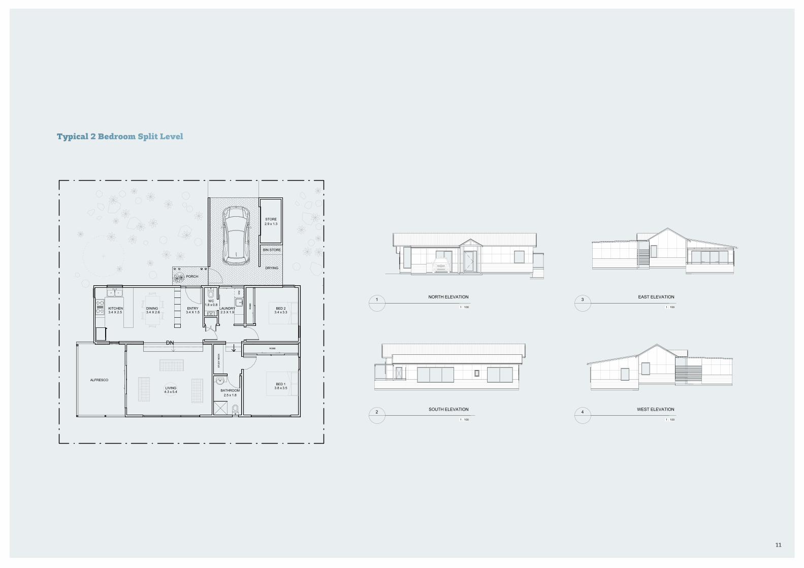
The Northam Eco Lifestyle Village has engaged experienced architect and designer Richard Hammond to design a range of modular homes that are uniquely suited to the sloping sites. The designs take advantage of the valley viewscapes and cooling breezes in the warmer months. They are also oriented for maximum solar warming in winter.
The modular homes will be manufactured offsite and are relocatable utilising reinforced concrete slabs with steel frames, double insulation and high-quality cladding materials. All homes feature open plan living with outdoor areas and decks to take advantage of the view corridors. Elevations have a natural colour palette in sympathy with the environment.
The sloping homesites will have minimal earthworks with the home modules taking advantage of the reinforced concrete slabs that can be suspended and supported on steel beams to sit above the ground. All homes will have either a carport or garage with generous enclosed storage areas and be sited to minimise steps for ease of access.
11
DNROBE
BATHROOM2.5 x 1.8
RO
BE
WM
ALFRESCO
STORE2.9 x 1.3
DRYING
PORCH
BIN STORE
NORTH
KITCHEN 3.4 X 2.5
DINING 3.4 X 2.6
WC 1.8 x 0.8
STUD
Y NO
OK
LAUNDRY 2.3 X 1.9
BED 2 3.4 x 3.3
BED 1 3.8 x 3.5LIVING
4.3 x 5.4
ENTRY 3.4 X 1.5
ScaleChecked by
Drawn by
Date
Project number
RICHARD HAMMOND ARCHITECT16/342 SOUTH TERRACE, SOUTH FREMANTLE0438 918 [email protected]
© 2016 Reproduction of the whole or part of this document constitutes an infringement of copyright. The information, ideas and concepts contained in this document are confidential. The recipient(s) of this document is/are prohibited from disclosing such information, ideas and concepts to any person without prior written consent of the copyright holder. 1 : 100
11/1
5/20
16 6
:34:
10 P
MFLOOR PLAN-NORTHAM VILLAGE
-
16.11.09
RHARHA
A100DWELLING 3 SPLIT LEVEL (2X2)NORTH
No. Description Date
ScaleChecked by
Drawn by
Date
Project number
RICHARD HAMMOND ARCHITECT16/342 SOUTH TERRACE, SOUTH FREMANTLE0438 918 [email protected]
© 2016 Reproduction of the whole or part of this document constitutes an infringement of copyright. The information, ideas and concepts contained in this document are confidential. The recipient(s) of this document is/are prohibited from disclosing such information, ideas and concepts to any person without prior written consent of the copyright holder. 1 : 100
11/1
5/20
16 6
:34:
10 P
MELEVATIONS-NORTHAM VILLAGE
-
16.11.09
RHARHA
A400DWELLING 3 SPLIT LEVEL (2X2)NORTH
1 : 100
NORTH ELEVATION1
1 : 100
SOUTH ELEVATION2
No. Description Date
1 : 100
EAST ELEVATION3
1 : 100
WEST ELEVATION4
Ground line omitted. Refer to site specific details.
Typical 2 Bedroom Split Level

12
KITCHEN4.3 x 2.5
DINING4.3 x 4.2
LIVING4.3 x 4.2
ALFRESCOSITE BUILT
ENTRYDECK
RO
BE
BED 13.4 x 3.6
ENSUITE2.3 x 1.6
BED 23.4 x 2.6 STUDY/MULTI PURPOSE
3.4 x 2.7
BATHROOM2.3 x 1.6
WM
LAUNDRY2.3 x 1.6
RO
BE
DRYING
NORTH
RO
BE
STORE3.0 x 2.5
BIN STORE
STUD
Y N
OO
K
ScaleChecked by
Drawn by
Date
Project number
RICHARD HAMMOND ARCHITECT16/342 SOUTH TERRACE, SOUTH FREMANTLE0438 918 [email protected]
© 2016 Reproduction of the whole or part of this document constitutes an infringement of copyright. The information, ideas and concepts contained in this document are confidential. The recipient(s) of this document is/are prohibited from disclosing such information, ideas and concepts to any person without prior written consent of the copyright holder. 1 : 100
15/1
1/20
16 6
:37:
53 P
MFLOOR PLANNORTHAM VILLAGE
16.11.15
RHARHA
A-100DWELLING 2 - 2 Bedroom w/Multi -Purpose Room
No. Description DateScaleChecked by
Drawn by
Date
Project number
RICHARD HAMMOND ARCHITECT16/342 SOUTH TERRACE, SOUTH FREMANTLE0438 918 [email protected]
© 2016 Reproduction of the whole or part of this document constitutes an infringement of copyright. The information, ideas and concepts contained in this document are confidential. The recipient(s) of this document is/are prohibited from disclosing such information, ideas and concepts to any person without prior written consent of the copyright holder. 1 : 100
15/1
1/20
16 6
:37:
56 P
MELEVATIONSNORTHAM VILLAGE
16.11.15
RHARHA
A-400DWELLING 2 - 2 Bedroom w/Multi -Purpose Room
1 : 100
NORTH ELEVATION1
1 : 100
SOUTH ELEVATION2
1 : 100
EAST ELEVATION3
1 : 100
WEST ELEVATION4
No. Description Date
GROUND LINES OMITTED REFER TO SITE SPECIFIC DETAILS
Typical 2 Bedroom & Multi-Purpose

13
BED 13.9 x 2.8
ENSUITE1.6 x 2.8
ENSUITE1.6 x 2.8
BED 32.9 x 3.2
LIVING4.3 x 4.9
DINING4.3 x 3.3
WIR
RO
BE
WM
ALFRESCOSITE BUILT
BIN STORE
STORE3 x 1.6
NORTH
BED 23.2 x 2.8 LAUNDRY
1.6 x 2.3
SCULLERY1.6 x 1.9
DRYINGCOURT
KITCHEN4.3 x 2.5
ScaleChecked by
Drawn by
Date
Project number
RICHARD HAMMOND ARCHITECT16/342 SOUTH TERRACE, SOUTH FREMANTLE0438 918 [email protected]
© 2016 Reproduction of the whole or part of this document constitutes an infringement of copyright. The information, ideas and concepts contained in this document are confidential. The recipient(s) of this document is/are prohibited from disclosing such information, ideas and concepts to any person without prior written consent of the copyright holder. 1 : 100
15/1
1/20
16 6
:38:
47 P
MFLOOR PLANNORTHAM VILLAGE
16.11.15
RHARHA
A100
DWELLING 1 - 3 BEDROOM
No. Description DateScaleChecked by
Drawn by
Date
Project number
RICHARD HAMMOND ARCHITECT16/342 SOUTH TERRACE, SOUTH FREMANTLE0438 918 [email protected]
© 2016 Reproduction of the whole or part of this document constitutes an infringement of copyright. The information, ideas and concepts contained in this document are confidential. The recipient(s) of this document is/are prohibited from disclosing such information, ideas and concepts to any person without prior written consent of the copyright holder. 1 : 100
15/1
1/20
16 6
:38:
49 P
MELEVATIONSNORTHAM VILLAGE
16.11.15
RHARHA
A400
DWELLING 1 - 3 BEDROOM
1 : 100
NORTH ELEVATION1
1 : 100
SOUTH ELEVATION2
No. Description Date
1 : 100
EAST ELEVATION3
1 : 100
WEST ELEVATION4
GROUND LINES OMITTED REFER TO SITE SPECIFIC DETAILS
Typical 3 Bedroom Home

14
Clubhouse Facilities
The Northam Eco Lifestyle Village will have an open feel ‘country clubhouse’ facility that will be built in a similar methodology to the housing, taking advantage of the spectacular views available nestled into the elevated hillside. Along with expansive decking and open multifunctional areas the Clubhouse will feature;
• Clubhouse entertaining area with stage
• Community kitchen/café area
• Gym and wellness centre
• Swimming pool & spa
• Lounge & fireside area
• Multifunction room/pool & billiards room
• Expansive open deck area
• Administration and sales centre
• Extensive under-croft storage area
In the Clubhouse precinct, there will be a practice bowling green and BBQ area set in a naturally enhanced landscaped area with a tree lined corridor that runs directly to the winter creek dam.
Community Facilities Centre Plan

15
Clubhouse Floorplan

16
Respecting the Town in the Valley
The Northam Eco Lifestyle Village is enviably located to represent a quality rural village at the town’s entrance.
The master-planning has considered in detail both the site attributes and the style and density of the lifestyle village housing ensuring enhanced liveability, respecting the unique countryside setting at the western entrance to Northam.
The combination of open corridors preserving the natural rock ridges and significant trees with green productive landscapes fed from local, non-potable water sources, provides a unique setting where many of the homes have direct access to the open space and magnificent views.

17

18
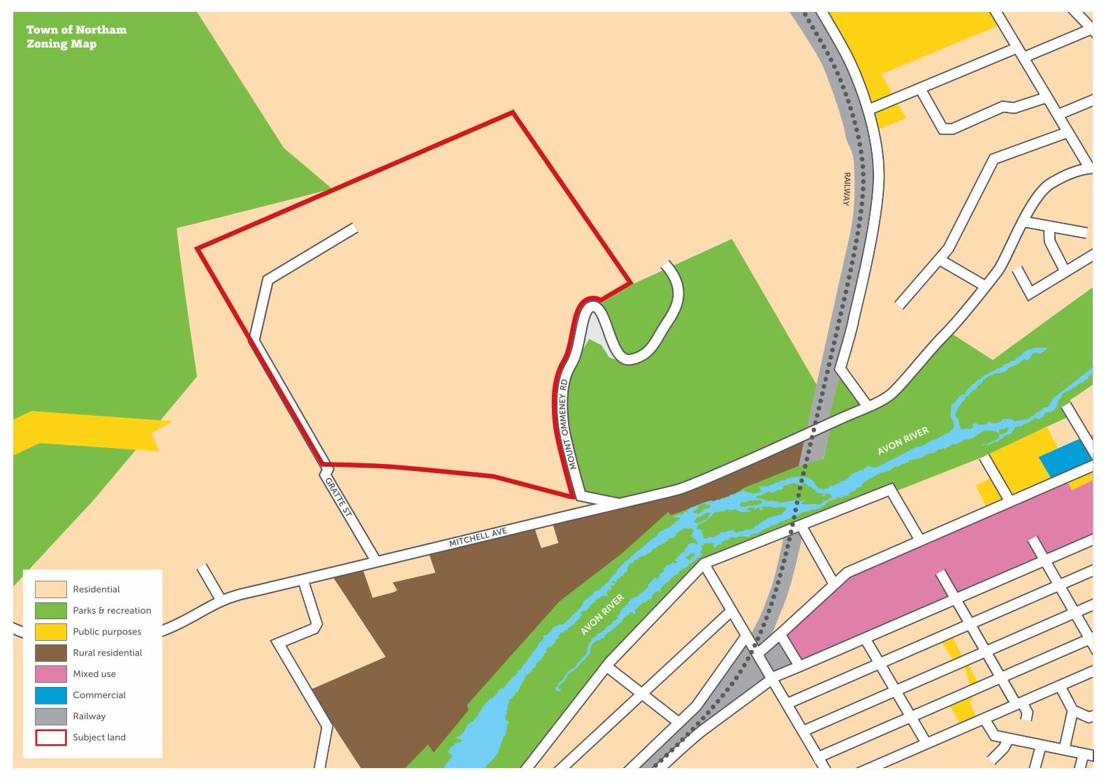
4. Planning ConsiderationsLot 9000 Ommaney Road sits on the western urban fringe of Northam in an area earmarked for urban expansion being zoned Residential R5 in the Town Planning Scheme No 6 for the Shire of Northam as depicted in the zoning map opposite.
Lot 9000 is generally bounded by Mt Ommanney Road to the east, Gratte Street and Avon View Crescent to the west, a Water Corporation reserve for the Mundaring-Kalgoorlie water main to the south and undeveloped Residential zoned land to the north.
The proposal for a 250 home Lifestyle Village under a land lease model does not propose subdivision for the homesites but rather seeks approval to develop and operate the land lease Lifestyle Village as an unlisted use (‘use not listed’) in Table 1 of the Shire’s Local Planning Scheme No 6.
The design of the Lifestyle Village respects the rural village feel of the Mount Ommanney precinct and will assist the Shire of Northam’s objective of providing a variety of affordable housing for seniors in both Northam, surrounding towns in the Wheatbelt and attracting people from Perth to retire in Northam.
19
AVON RIV
ER
AVON RIVER
MITCHELL AVE
GR
ATTE ST
MO
UN
T O
MM
EN
EY R
D
RA
ILWA
Y
Residential
Parks & recreation
Public purposes
Rural residential
Mixed use
Commercial
Railway
Subject land
Town of Northam Zoning Map

20
5. Engineering and Services Considerations

21
Lot 9000 Ommaney Road sits on the western urban fringe of Northam in an area earmarked for urban expansion being zoned Residential R5 in the Town Planning Scheme No 6 for the Shire of Northam as depicted in Figure 7.
Lot 9000 is generally bounded by Mt Ommanney Road to the east, Gratte Street and Avon View Crescent to the west, a Water Corporation reserve for the Mundaring-Kalgoorlie water main to the south and undeveloped Residential zoned land to the north.
The proposal for a 250 home Lifestyle Village under a land lease model does not propose subdivision for the homesites but rather seeks approval to develop and operate the land lease Lifestyle Village under a ‘use not permitted’ provision in the Scheme as a Park Home Park in Residential zoned land.
The design of the Lifestyle Village respects the rural village feel of the Mount Ommanney precinct and will assist the Shire of Northam’s objective of providing a variety of affordable housing for seniors in both Northam, surrounding towns in the Wheatbelt and attracting people from Perth to retire in Northam.
Existing Site Conditions
The site’s natural topography generally falls from north to south at an average grade of approximately 5% with levels falling from 236m AHD at the site’s highest point on the north eastern boundary to 156m AHD at the lowest point in the site’s south eastern corner. A very shallow natural creekline runs from north to south across the site into a farm dam located around the centre of the site.
The local geology is granite rock which weathers to a coarse grained sandy material containing a small percentage of clay overlying granite boulders and bedrock. A geotechnical report by CWM has been prepared for the site and is included in Appendix 3 and classifies the Site as Category M.
Roads and Traffic
Access to the site is from either Gratte Street on the site’s western boundary or Mt Ommanney Road on the site’s eastern boundary.
The site’s current main access is via Mt Ommanney Road which is a sealed road with a 6m wide pavement in a 20m wide road reserve. Gratte Street is also a 20m wide reserve with a 6m wide unsealed gravel road.
The proposed development masterplan for the Northam Eco Lifestyle Village has the main entry off Mt Ommanney Road with secondary emergency exit available to Gratte Street.
As a private estate the internal roads are maintained by the Lifestyle Village operator and the road reserves will be 6m wide. The design has catered for local council bin points for pick up at designated areas for each cluster of homes in the Northam Eco Lifestyle Village.
From a village of 250 homes with an expected longer term occupancy of 1.5 persons per dwelling and with the majority of people being retired or semi-retired, the likely traffic movements will have a minimal impact on Mt Ommanney Road and almost negligible on Gratte Street as the emergency secondary access road. A traffic impact assessment will be conducted as part of the proposed DA conditions.
Bushfire Management
The proposed development on the mid to lower slopes of the site provides a development footprint downslope from the northern ridgeline and treed upper slopes of Mt Ommanney. The bushland on the eastern side of Mt Ommanney Road whilst separated from the development site is adjacent and provides some fuel loads that need to be managed and acknowledged as this land is earmarked to be retained as public open space.
A bushfire assessment report will be conducted as a part of the proposed DA conditions and all dwellings and habitable buildings will be designed and constructed in accordance with the BAL rating.

22
Water Supply
Potable Water
The Water Corporation’s DN900 Mundaring- Kalgoorlie water pipeline runs in a reserve along the site’s southern boundary. There is an existing DN100 water main on Gratte Street on the site’s western boundary, which comes off the Mundaring-Kalgoorlie pipeline and services the properties located along Gratte Street.
The existing DN 100 water main in Gratte Street is sufficient to service the private development with potable water with internal enhancement of pressure as a part of the private works as required to service the more elevated portions of the Lifestyle Village site.
Non Potable Water Supply
From the masterplan design of the Village to the homes and the landscape treatment all aspects of the Northam Eco Lifestyle Village optimise water collection and retention and reuse.
Sources of non-potable supply include:
• Natural winter creek flow into reconstructed dam
• Stormwater from the roads and roof runoff will be directed via swales to the dam and the lower retention basin for irrigation of the productive landscapes and open spaces.
• Groundwater from on-site bore already drilled is fresh and of sufficient quantity to supplement the irrigated landscape.
• Treated wastewater from the homes will be irrigated to the productive landscapes and open spaces between the clusters of homes. This wastewater will be treated through the on-site Aerobic Treatment Units (ATU) which will significantly reduce Nitrogen and Phosphorous levels and disinfect the water with Ozone providing safe recycled water for sub-surface irrigation.
By optimising the capture and reuse of these sources of non-potable supply it will enable the Northam Eco lifestyle Village to preserve potable supply for in house use only reducing demand considerably.
Stormwater Management
Stormwater runoff from within the Lifestyle Village will be managed via roadside swales wherever possible to capture and reinfiltrate runoff at source and minimise the requirement for formal piped stormwater drainage.
The existing farm dam and the informal creekline through the north of the site are intended to be retained and enhanced through a public open space corridor through the lifestyle village. The dam and additional stormwater retention area at the southern end of the site will be used to retain and remove nutrients from stormwater runoff and attenuate flows in major storm events.
Wastewater Management
The site is remote from reticulated sewer and on-site secondary wastewater treatment and recycling will boost site-generated non-potable supplies and ensure potable water is not used on the gardens and landscape areas.
The preferred on-site secondary wastewater treatment system is the Aquarius 0-3 Alternative Treatment Unit.
The Aerobic Treatment Units are designed and engineered in Germany and assembled and supported in Australia by Aquarius. The robust and durable injection moulded tanks deliver:
• reliable treatment of wastewater under SBR (sequential batch reactor) technology
• automatic sludge return
• Nitrate and Phosphate reduction
• Advanced air lift technology in place of pumps
• Lower operating and maintenance costs
All units are to Australian Standard Certification and are WA Health Department Approved.
With ozone treatment built in to the unit, the treated wastewater is disinfected to a standard verified by the Health Department as suitable for irrigation both sub-surface and via sprinkler.

23
O2
2080 mm
H/Water AlarmFloat Switch
FGL FGL
WL
SecondaryAerationChamber
ClarifyingChamber
DisinfectionDischargeChamber
1400 mm
290 mm - 610 mm
140 mm - 340 mm
Alum Tank600 x 1060mm deep
Slab
Electrical Control Panel& Ozone Box
O3
Main ControlFloat Switch
to Drippers / SprinklersLeach Drains / Soakwells
WL
Sludge Level
2400 L
2080 mm
Anaerobic Chamber
WL
PRIMARY TANK TREATMENT TANK
AQUARIUSWASTEWATER MANAGEMENT SYSTEMS
0-3 ALTERNATIVE Treatment Unit
(Domestic 10 Person Equivalent)
*Poly tank version shown. Also available in concrete tanks.
AS/NZS 1546.3Lic SMKH21519
SAI Global
AS/NZS 1546.3Lic SMKH21519
SAI Global
Aquarius® Systems1 – 5 Bedrooms O-3 ATU O-2 NR ATU O-2 ATU
6 – 9 Bedrooms O-3 3KL ATU O-2 NR 3KL ATU O-2 3KL ATU
Commercial Aquarius® Standard or Custom Designed Commercial Systems
Please speak to our Sales Consultant
SpecificationsO-3 O-2 NR O-2
System Features
Poly/Duralen Plastic or Concrete Tank Construction ✓ ✓ ✓
Nutrient Retentive (Phosphorous reduction) ✓ ✓
Ozone Disinfection ✓
Recycles all wastewater through irrigation into gardens, orchards, etc. ✓ ✓ ✓
Supplied complete with irrigation components, electrical components and pumps ✓ ✓ ✓
Footprint required approx 6m x 2.5m x 2m** ✓ ✓ ✓
Low Energy use ✓ ✓ ✓
Irrigation Area
Above Ground Spray IrrigationSub-Surface Dripper IrrigationIrrigation area in sandy soil conditions –*150m2
✓
✓
✓
✓
✓
✓
✓
Other Disposal OptionsLeach Drains / Soakwells / Aquasafe Drains
✓
✓
✓
MaintenanceService calls per year as per DoH WA requirements 2 2 2
Manufacturers WarrantiesPoly/Duralen Plastic Tanks 15 yearsOrange Pumps 1 yearIrrigation and Electrical components 1 year
✓
✓
✓
✓
✓
✓
✓
✓
✓
ApprovalsFully approved by the Department of Health
✓
✓
✓
Australian Standards approved AS/NZS 1546.3 ✓ ✓ ✓
Why choose AquariusWholly owned West Australian Company ✓ ✓ ✓
Manufactured in Western Australia ✓ ✓ ✓
Extensive Support Network covering all of WA ✓ ✓ ✓
Local Agents fully trained and registered with Department of Health WA ✓ ✓ ✓
*Subject to local authority approval.
Aquarius® Alternative Treatment UnitsThe complete range of Aquarius® ATUs treat all the wastewater from the residential home or commercial site. The wastewater (from WC, kitchen, bathroom and laundry) is treated to current Department of Health WA Standards that allows it to be used for irrigation in garden beds, orchards, etc., or disposal into leach drains, soakwells and aquasafe drains. In addition the O-2 NR and O-3 models further treat the water to reduce phosphorous and nitrogen and these two ATU models are classified as nutrient retentive which is essential in water catchment areas, environmental sensitive areas and to comply with some local shire requirements.
The Aquarius® O-3 ATU we believe to be the most environmentally friendly ATU on the market by using Ozone as the final disinfection process. Ozone is many times more effective than chlorine and the by-product of Ozone is Oxygen.
The decision to use a Health Department approved ATU with secondary treatment chambers for aeration, clarification and disinfection provides a higher level treatment and thereby produces a fit for purpose source of non-potable irrigation water. Key aspects that support this safe and sustainable use of these ATUs are:
• the site is not in a sewage sensitive area
• it is likely that the 4kL ATU systems will be used with 3 large tanks as these are sized sufficiently to service a 20-lot stage based on average occupancy rates per home which will simplify operations and provide greater redundancy capacity
• taking into consideration the soil types and geotechnical information, there is more than adequate separation from groundwater to exceed the 0.6 to 1.5m requirement
• the method of irrigation will be sub-surface and in the landscaped areas within each stage of the Village with more than twice the land area required being available
• stand-by pumps will be in the ATUs as back up and innovative leach drains will be installed to manage overflow in case of power disruption
• residents in the village will be educated on the management of the system including what chemicals upset the system and the eco lifestyle philosophy encourages behaviour that respects the water cycle and the reduce, reuse and recycle outcome
• the maintenance rests with the Lifestyle Village owner who is on site

24
Power
Existing Infrastructure
Existing overhead Western Power HV distribution lines run along Mitchell Avenue and Gratte Street and also to the tower at the top of Mt Ommanney Road. There is also existing LV overhead power lines on Mitchell Avenue and Gratte Street servicing existing properties. The location of existing Western Power infrastructure and network capacity is shown in the Engineering Services Report in Section 6.2.
Network Capacity
Western Power’s network capacity mapping tool (NCMT) shows that the network has remaining capacity of <5MVA to service new connections to the network which is sufficient to service the potential demands of this development.
The Northam Eco Lifestyle Village will require substantially less electricity from the network as a combination of solar arrays with banks of batteries will be optimised and staged to grow to deliver capacity to the local village grid requiring limited back up from the conventional Western Power grid.
In discussions with senior executives from Western Power there is appetite to explore an innovative trial providing power generation benefits to both parties.
Gas
There is no reticulated gas network in Northam and any internal gas supply will need to be via bottled gas supply.
Communications
Telstra has existing infrastructure in Mitchell Avenue and Gratte Street to service the existing properties in the area. It is envisaged that telecommunications and broadband infrastructure in this development would be supplied via the National Broadband Network (NBN) which will involve the installation of an approved pit and pipe system as part of the development.
The NBN rollout is enabled to commence in this area and an application for this service is pending.

25

26
6. SustainabilityThe Northam Eco Lifestyle Village is designed to ‘do more with less’ with natural resources and touching lightly the landscape with homes and structures that minimise earth-working and retaining walls. Lower use of utility services of potable water and power not only reduces user costs but generate a much lower carbon footprint.
It is estimated that the Eco Lifestyle Village will achieve a 40% reduction in potable water use, with only non-potable sources used outside the dwellings and Clubhouse.
Reliance on conventional Western Power grid solution will be significantly reduced by up to 80% with solar/battery system managed by a third party in conjunction with the Lifestyle Village operator allowing electron sharing and cost transfers between users in the Village at lower than grid scheme costs.
With productive edible landscapes watered from local non potable sources, green corridors will be created between the clusters of hillside homes providing fresh fruits, nuts and vegetables for the village residents.
Social connection and community based activities will be central to the Northam Eco Lifestyle Village and will create a vibrant connected community that will contribute to the local Northam economy.
The philosophy of H&H’s Eco Lifestyle Villages is well aligned to the One Planet Living international sustainability initiative and hence the Village will seek independent assessment against the framework.
One Planet Living is an initiative of Bioregional and its partners to make truly sustainable living a reality. One Planet Living uses ecological footprinting and carbon footprinting as its headline indicators. It is based on ten guiding principles of sustainability as a framework.

27
One Planet LivingThe Northam Eco Lifestyle Village
will be seeking accreditation under the One Planet Living model which
incorporates best practice design and sustainable living practices
across 10 One Planet Principles.
Health & HappinessEncourages active, sociable, meaningful lives to promote good health and well-being.
Equity & Local EconomyCreating bioregional economies that support equity and diverse local employment and international fair trade.
Culture and CommunityRespecting and reviving local identity, wisdom and culture; encouraging the involvement of people in shaping their community and creating a new culture of sustainability.
Land Use & WildlifeProtecting and restoring biodiversity and creating new natural habitats through good land use and integration into the built environment.
Sustainable WaterUsing water efficiently in buildings, farming and manufacturing. Designing to avoid local issues such as flooding drought and water course pollution. Local & Sustainable Food
Supporting sustainable and humane farming, promoting access to healthy,
low impact, local, seasonal and organic diets and reducing food waste.
Sustainable MaterialsUsing sustainable and healthy products, such as those with
low embodied energy, sourced locally, made from renewable or
waste resources.
Sustainable TransportReducing the need to travel
and encouraging low and zero carbon modes of transport to
reduce emissions.
Zero WasteReducing waste, reusing where possible and ultimately sending
zero waste to landfill.
Zero CarbonMaking buildings energy
efficient and delivering all energy with renewable
technologies.

28
7. ImplementationThe Northam Eco Lifestyle Village will be staged over an 8 to 10 year period based on demand and with stages providing leasehold sites for approximately 20 homes being produced annually.
The Clubhouse facility will be completed in the first two years to provide amenity and facilities that will enhance the lifestyle for those residents moving in to the Village as it begins.
A display village showcasing the homes will be built as a part of Stage 1 along with the main entrance. Specific home types will be pre-allocated for each homesite to optimise site orientation and landform.
The existing winter creek dam will be redesigned and reconstructed as a part of Stage 1 to capture stormwater runoff along with the lower retention basin.
Depending on the development approval, it is envisaged that on site earthworks will commence in mid-2017 with the display village opening in November 2017.

29
8. ConclusionThe Northam Eco lifestyle Village will fill a market demand for people over 45 who are seeking to downsize and enjoy country living on the city’s doorstep. The marketing of Northam will be key in focussing the Perth market on looking east and not endlessly north and south along the coastal plain for a lifestyle and a town that has so much to offer.
The development will provide a sustainable boost to the local Northam economy and hopefully underpin the continued operation of the train service to Perth.
H&H Development Enterprises looks forward to working with the Shire and respectfully seeks the support of the Shire and Councillors for the expeditious approval of the Northam Eco Lifestyle Village.

30
9. AppendicesAppendix 1: Certificate of Title Page 31
Appendix 2: Engineering Report - Wave Engineering Page 32
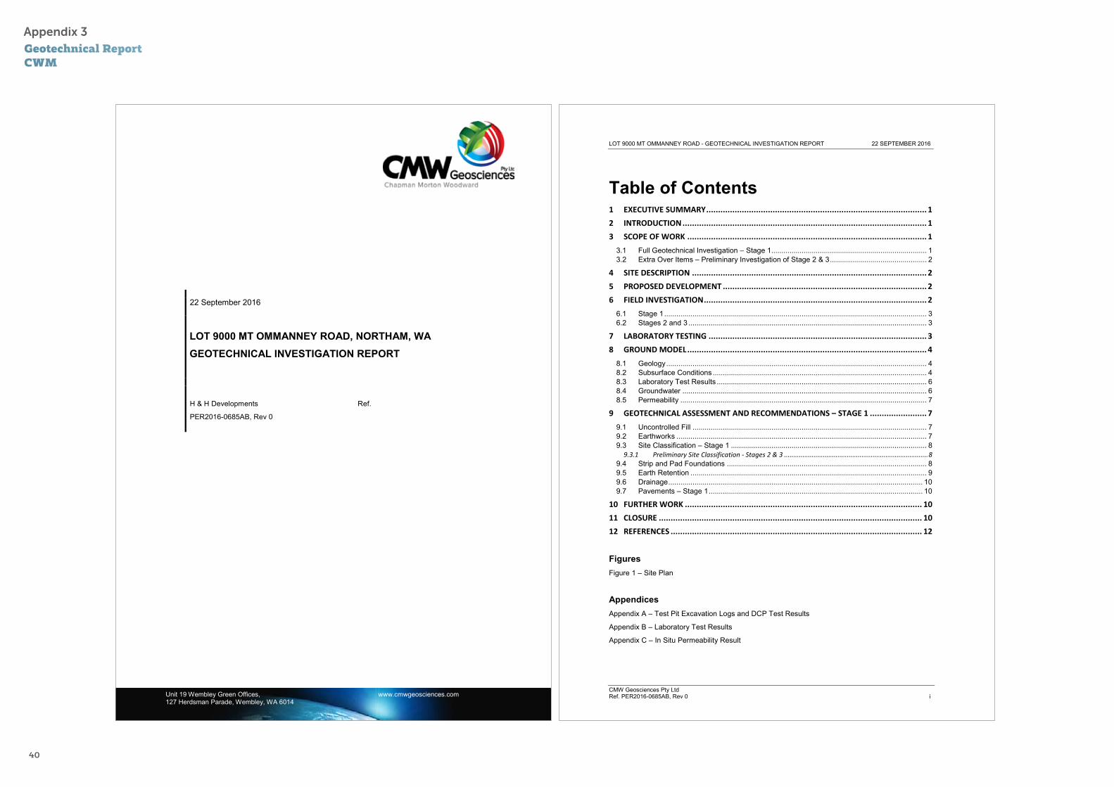
Appendix 3: Geotechnical Report - CWM Page 40

31
Appendix 1Certificate of Title

32
LOT 9000 MT OMMANNEY ROAD, NORTHAM
Infrastructure Servicing Report
H&H Development Enterprises
November 2016
i 4293-30-RPT-CI-21001.docx
306 Murray Street, Perth Western Australia 6000 PO Box 7085, Cloisters Square Western Australia 6850
PROJECT BRIEF
Project number 4293
Project title Lot 9000 Mt Ommanney Road, Northam
Infrastructure Servicing Report
Client H&H Development Enterprises
Client contact Mike Hollett
Client address Suite 24, 25 Walters Dve, Osborne Park WA 6017
DOCUMENT STATUS
Rev Date Description By Reviewed Approved
A 16 June 2016 Draft for client review KW SW SW
B 14 November 2016 Updated following client review KW SW SW
DISCLAIMER
This document has been produced on behalf of, and for the exclusive use of the nominated recipient, and is issued for the purposes of the proposed works only. Wave International accepts no responsibility or liability
whatsoever in respect to use of this document by any third party.
The information contained within the document is confidential and subject to copyright.
This document shall not be copied, transmitted or divulged to other parties without the prior written consent of
Wave International’s duly authorised representative.
Appendix 2Engineering ReportWave Engineering

33
Lot 9000 Mt Ommanney Road, Northam_
ii 4293-30-RPT-CI-21001.docx
TABLE OF CONTENTS
1 INTRODUCTION .......................................................................... 1
1.1 Background ................................................................................................................ 1
1.2 Proposed land use ....................................................................................................... 1
1.3 Existing site conditions ................................................................................................. 1
2 ROADS & TRAFFIC ...................................................................... 2
3 WASTEWATER ........................................................................... 2
3.1 Existing infrastructure .................................................................................................. 2
3.2 Wastewater management .............................................................................................. 2
4 POTABLE WATER ........................................................................ 3
4.1 Existing infrastructure .................................................................................................. 3
4.2 Potable water supply .................................................................................................... 3
4.3 Non-potable water supply .............................................................................................. 3
5 STORMWATER MANAGEMENT .......................................................... 4
5.1 Existing infrastructure .................................................................................................. 4
5.2 Stormwater drainage strategy ......................................................................................... 4
5.3 Flood management strategy ........................................................................................... 4
6 POWER ................................................................................... 5
6.1 Existing infrastructure .................................................................................................. 5
6.2 Network capacity ........................................................................................................ 5
6.3 Funding .................................................................................................................... 6
7 GAS ....................................................................................... 6
8 COMMUNICATIONS ...................................................................... 6
8.1 Existing infrastructure .................................................................................................. 6
8.2 Communications provision ............................................................................................. 6
Lot 9000 Mt Ommanney Road, Northam_
iii 4293-30-RPT-CI-21001.docx
LIST OF FIGURES Figure 1 – Locality plan
Figure 2 – Aerial photo
Figure 3 – Concept layout
Figure 4 – Existing services – water
Figure 5 – Existing services – Western Power
Figure 6 - Existing services - Telstra

34
Lot 9000 Mt Ommanney Road, Northam_
1 4293-30-RPT-CI-21001.docx
1 INTRODUCTION
1.1 Background
Wave International has been commissioned by H&H Development Enterprises to prepare an infrastructure
servicing report for Lot 9000 Mt Ommanney Road in Northam. The site is located on the western edge of the
Northam townsite, approximately 100km east of Perth.
Lot 9000 is generally bounded by Mt Ommanney Road to the east, Gratte Street and Avon View Crescent to the
west, a Water Corporation reserve for the Mundaring-Kalgoorlie water main to the south, and undeveloped rural
land to the north.
This infrastructure servicing report has been prepared to support a development application to the Shire of
Northam over Lot 9000. Figure 1 shows the site’s location, and Figure 2 shows an aerial photo of the site.
1.2 Proposed land use
Lot 9000 Mount Ommanney Road is approximately 50ha in area is currently zoned Residential (R5) under the
Shire of Northam’s Town Planning Scheme No 6.
This infrastructure servicing report has been prepared to support a development application for the site, which
is intended to be developed as a ~250-lot lifestyle village (in the central and south-eastern parts of the site),
with remnant undeveloped land to the north and west, surrounding the lifestyle village.
A concept development plan for the site is included as Figure 3.
1.3 Existing site conditions
The site’s natural topography generally falls from north to south at an average grade of approximately 5%, with
levels falling from 236mAHD at the site’s highest point on the north-eastern boundary to 156mAHD at the lowest
point in the site’s south-eastern corner. A very shallow natural creekline runs from north to south across the
site, into a farm dam located around the centre of the site.
The published geological mapping for the area indicates that the site conditions are expected to be variably
weathered granitoid rock overlain by residual and colluvial/alluvial deposits of sand, clay and loam.
A geotechnical site investigation was carried out by CMW Geosciences on 30 August 2016, which found that the
site conditions were generally consistent with the published geology for the area. The site investigation found
the site to be underlain by sands, sandy clay, clay and clayey sand overlying weathered granite which becomes less weathered at depth. The in-situ sands and extremely weathered granite materials can be readily excavated,
while rock breaking equipment may be required to excavate below the test pit refusal depths which ranged from
0.75m to 2.1m below natural surface level.
Lot 9000 Mt Ommanney Road, Northam_
2 4293-30-RPT-CI-21001.docx
2 ROADS & TRAFFIC Access to the site is from either Gratte Street on the site’s western boundary or Mt Ommanney Road on the
site’s eastern boundary.
The site’s current main access is via Mount Ommanney Road, which is a sealed road with a ~6m wide sealed
pavement in a 20m wide road reserve. Gratte Street is also a 20m wide reserve with a ~6m wide unsealed gravel
road.
The proposed development concept plan shows access the main access to the lifestyle village being from Mt
Ommanney Rd on the site’s eastern boundary, with a secondary access via Gratte Street on the site’s western boundary.
The site will be a land-leased lifestyle village, with internal roads owned and maintained by the village. The
internal access roads are expected to be 6m wide with a 4m pavement.
3 WASTEWATER
3.1 Existing infrastructure
The Water Corporation does not have any existing wastewater infrastructure in the immediate vicinity of the
site, with the nearest Water Corporation gravity sewer located approximately 1km to the east of the site, on Mitchell Avenue.
3.2 Wastewater management
Wastewater would typically be required to discharge to the Water Corporation’s sewer reticulation network,
approximately 1km east of the site. However, an exemption applies under the Water Services Act 2012 for
“water service providers providing water services on single premises under their control or management”. This
exemption applies to property managers (including the operators of a lifestyle village) from having to obtain a water service licence from the Economic Regulation Authority for wastewater recycling systems (of a capacity up
to 20kL/day), where the recycled wastewater is to be used for non-drinking purposes in accordance with the
Department of Health’s Guidelines for the Non-Potable Uses of Recycled Water In Western Australia 2011.
For this site, innovative solutions will be considered in consultation with the project’s sustainability consultant
to investigate the potential for re-use of treated wastewater for irrigation of crops, to minimise the use of
scheme water or groundwater inside the development.
Some other alternatives for wastewater disposal include in-house greywater recycling via the separation of
greywater & blackwater, or the use of constructed wetlands for treated wastewater disposal.
A land lease development will provide flexibility in the implementation of alternative or innovative wastewater treatment solutions, as the system can be managed and controlled by the village rather than individual home
owners.

35
Lot 9000 Mt Ommanney Road, Northam_
3 4293-30-RPT-CI-21001.docx
4 WATER
4.1 Existing infrastructure
The Water Corporation’s DN900 Mundaring-Kalgoorlie water pipeline runs in a reserve along the site’s southern
boundary. There is an existing DN100 water main on Gratte Street on the site’s western boundary, which comes
off the Mundaring-Kalgoorlie pipeline and services the properties located along Gratte Street. Figure 4 shows the existing Water Corporation infrastructure near the site.
4.2 Potable water supply
The existing DN100 water main in Gratte Street is intended to supply the initial stages of the development, and
an application will be made to the Water Corporation for a service from this existing main. The internal water
pressures within the estate will be managed by the village, and may include the use of ground-level storage
tanks to service houses at the higher elevations.
4.3 Non-potable water supply
The intention for the design of the development is to minimise potable water use wherever possible, which can be achieved by using alternative water sources for all non-potable purposes, including toilet flushing, washing
machines, and garden & public open space irrigation.
The use of rainwater tanks that are plumbed into the house for toilet flushing & washing machine use can be a
more effective method of reducing potable water use than using captured rainwater for garden irrigation, as approximately 75% of Northam’s rainfall typically falls between May and September when irrigation of garden
areas is not usually necessary.
Treated wastewater can provide a more constant water supply for irrigation purposes, particularly during the
summer months.
Stormwater capture and reuse will also be investigated for this development - a water balance study will be required to determine the feasibility of using the existing farm dam for stormwater storage over the winter
months for re-use during the summer months. This will form part of an urban water management plan for the
site, which is expected to be a condition of a DA for the proposed development.
Lot 9000 Mt Ommanney Road, Northam_
4 4293-30-RPT-CI-21001.docx
5 STORMWATER MANAGEMENT
5.1 Existing infrastructure
The northern boundary of the site generally coincides with the surface runoff catchment boundary for
stormwater runoff. Stormwater is conveyed via overland flow to an existing farm dam located towards the
centre of the site.
Runoff from the southern part of the site will most likely be captured by the shallow v-drains along Mitchell
Avenue to the south of the site, before being conveyed to the Avon River. The Shire’s drainage infrastructure in
Mitchell Avenue and adjacent road reserves will need to be surveyed to confirm levels & locations before
detailed design of the development.
5.2 Stormwater drainage strategy
Stormwater runoff from within the development will be managed via roadside swales wherever possible to capture and reinfiltrate runoff at-source and minimise the requirement for formal piped stormwater drainage.
The existing farm dam and the informal creekline through the north of the site are intended to be retained and
enhanced through a public open space corridor through the lifestyle village. The dam and additional stormwater
retention areas at the southern end of the site can be used to retain stormwater runoff and attenuate flows in
major storm events.
A water balance for the site will be undertaken to establish whether the existing dam and new stormwater
basins can be used for the effective capture and storage of stormwater runoff for irrigation purposes over the
summer months.
An urban water management plan is expected as a condition of the development application for the site, under
the Department of Planning’s Better Urban Water Management framework. This UWMP will present the stormwater management strategies that are proposed for implementation across the development, including
details of how these measures will be implemented and ongoing maintenance and monitoring responsibilities.
5.3 Flood management strategy
To ensure that developed areas are not subjected to flooding, the site will be designed to divert surface runoff
towards the central POS corridor, and to discharge the site via the existing pre-development flow paths.
Stormwater modelling will be required to ensure that post-development runoff rates do not exceed pre-development levels, to protect downstream environments from flooding.

36
Lot 9000 Mt Ommanney Road, Northam_
5 4293-30-RPT-CI-21001.docx
6 POWER
6.1 Existing infrastructure
Existing overhead Western Power HV distribution lines run along Mitchell Avenue and Gratte Street, and also to
the tower at the top of Mount Ommanney Rd. There is also existing LV overhead power lines on Mitchell Ave and
Gratte Street servicing existing properties. The location of existing Western Power infrastructure is shown on Figure 5.
6.2 Network capacity
Western Power’s network capacity mapping tool (NCMT) shows that the network has a remaining capacity of
<5MVA to service new connections to the network, as shown in the image below.
The developers of the proposed lifestyle village intend to minimise the use of electricity from Western Power’s
network through the use of solar energy and community battery storage as the predominant source of electricity for the homes and village operations.
The Western Power NCMT does not indicate the need for a new feeder or other HV network upgrades, which can
only be determined at detailed design stage. The allocation of remaining capacity to service new developments
is determined on a first-come first-served basis when a development application is lodged.
A Feasibility study should be conducted by Western Power to determine optimum infrastructure requirements on
and to provide an estimate of any HV upgrade works that may be required.
Lot 9000 Mt Ommanney Road, Northam_
6 4293-30-RPT-CI-21001.docx
6.3 Funding
The extension of any HV infrastructure to the subject site will likely be a developer funded project, depending
on the staging of the development and whether the initial stages meet the economic test of the Western Power HV Pool. Developers may be entitled to a capital contribution from Western Power if capacity provided in the HV
extension/upgrade is in excess of that required for the specific project.
7 GAS There is no reticulated gas network in Northam, and any internal gas supply will need to be via bottled gas
supply.
8 COMMUNICATIONS
8.1 Existing infrastructure
Telstra has existing infrastructure in Mitchell Avenue and Gratte Street to service the existing properties in the
area. Figure 6 shows the extent of Telstra’s existing infrastructure.
8.2 Communications provision
It is envisaged that telecommunications and broadband infrastructure in this development would be supplied via
the National Broadband Network (NBN) which requires developers to install an approved pit and pipe system as
part of the development. .
The NBN is currently available via a fixed wireless service in the area of the proposed development, and the
developer has commenced discussions with NBN Co for the provision of services to the site.

37
SITE LOCATION
Job NumberRevision
Date
WAVE INTERNATIONAL PTY LTDMezzanine,306 Murray StreetPERTH, WA 6000Telephone: +61 8 92040700Email: [email protected]: www.waveinternational.com
C:\projectwise\wrk\pwdata\yvermaak\dms08650\4293-40-SKT-CI-20001.dwg - yvonne vermaak - 16/06/2016
H & H DEVELOPMENT ENTERPRISESLOT 9000 MT OMMANNEY ROAD, NORTHAM
LOCALITY PLAN
1955-4293AJUNE 2016
FIGURE 1
IMAGE SOURCE : GOOGLE MAPS
455
201
51
4
456
503
458
50
2
11
5
9000
11
54
3
700
459
55
457
56
503
7
701
340
267
LOT 900050.81 ha
RD
VERLINDEN
GRATTE
ST
RD
MO
UN
T OM
MAN
NEYG
RATTE
ST
RD
MT
OMM
ANNE
Y
AVO
N V
IEW
CR
MITCHELL
AV
C:\projectwise\wrk\pwdata\yvermaak\dms08650\4293-40-SKT-CI-20002.dwg - yvonne vermaak - 16/11/2016 1:26:54 PM
H & H DEVELOPMENT ENTERPRISESLOT 9000 MT OMMANNEY ROAD, NORTHAM
AERIAL PHOTO
1955-4293BNOVEMBER 2016
FIGURE 2
IMAGE SOURCE : NEARMAPS
LEGEND
SITE BOUNDARY

38
RD
VERLINDEN
GRATTE
ST
RD
MO
UN
T OM
MAN
NEYG
RATTE
ST
RD
MT
OMM
ANNE
Y
AVO
N V
IEW
CR
DR
MITCHELL
544 20555
455
201
51
4
456
14
503
458
50
2
11
5
9000
11
54
3
700
459
55
457
56
503
12
7
701
340
13
267
LOT 900050.81 ha
C:\projectwise\wrk\pwdata\yvermaak\dms08650\4293-40-SKT-CI-20003.dwg - yvonne vermaak - 16/11/2016 1:21:09 PM
H & H DEVELOPMENT ENTERPRISESLOT 9000 MT OMMANNEY ROAD, NORTHAM
CONCEPT LAYOUT
1955-4293BNOVEMBER 2016
FIGURE 3
LEGEND
SITE BOUNDARY
FR
900S-11-W
58AC
900S-8-W
1130S-11-W
63MDPE
900S-10-W
58AC
58AC
100P-12
58AC
1130S-11-W
JX61
MUNDARING - KALGOORLIE PIPELINE
MH
MH
50M
AV
50M
AV
1130S-10-WMUNDARING - KALGOORLIE PIPELINE
RD
VERLINDEN
GRATTE
ST
RD
MO
UN
T OM
MAN
NEYG
RATTE
ST
RD
MT
OMM
ANNE
Y
AVO
N V
IEW
CR
DR
MITCHELL
544 20555
455
201
51
4
456
14
503
458
50
2
11
5
9000
11
54
3
700
459
55
457
56
503
12
7
701
340
13
267
LOT 900050.81 ha
C:\projectwise\wrk\pwdata\yvermaak\dms08650\4293-40-SKT-CI-20004.dwg - yvonne vermaak - 16/11/2016 1:20:44 PM
H & H DEVELOPMENT ENTERPRISESLOT 9000 MT OMMANNEY ROAD, NORTHAM
EXISTING SERVICESWATER
1955-4293BNOVEMBER 2016
FIGURE 4
LEGEND
EXISTING WATER PIPE WITH ANNOTATION
SITE BOUNDARY
11305-11-W

39
OH
OHO
HOH
OH
OH
OH
OHO
HOH
OH
OHO
HOH
OHOH
OHOH
OHOH
OHOH
OHOH
OHOH
OHOH
OHOH
OHOH
OHOH
OHOH
OHOH
OH
OHOH
OH
OH
OH
OH
OH
OHOH
OHOH
OHOH
OHOH
OHOH
OHOH
OHOH
OH
OH
OH
OH
OH
OH
OH
OH
OH
OH
OH
OH
OH
RD
VERLINDEN
GRATTE
ST
RD
MO
UN
T OM
MAN
NEYG
RATTE
ST
RD
MT
OMM
ANNE
Y
AVO
N V
IEW
CR
DR
MITCHELL
AV
544 20555
455
201
51
4
456
14
503
458
50
2
11
5
9000
11
54
3
700
459
457
503
12
7
701
340
13
LOT 900050.81 ha
C:\projectwise\wrk\pwdata\yvermaak\dms08650\4293-40-SKT-CI-20005.dwg - yvonne vermaak - 16/11/2016 1:20:20 PM
H & H DEVELOPMENT ENTERPRISESLOT 9000 MT OMMANNEY ROAD, NORTHAM
EXISTING SERVICESWESTERN POWER
1955-4293BNOVEMBER 2016
FIGURE 5
LEGEND
OVERHEAD LOW VOLTAGE POWERLINE
OVERHEAD HIGH VOLTAGE POWERLINE
PILLAR
SITE BOUNDARY
OH OH OH
OH OH OH
TT
TT
TT
TT
TT
TT
TT
TT
TT
T
TT
TT
T
TT
TT
TT
TT
TT
T
TT
T
RD
VERLINDEN
GRATTE
ST
RD
MO
UN
T OM
MAN
NEYG
RATTE
ST
RD
MT
OMM
ANNE
Y
AVO
N V
IEW
CR
DR
MITCHELL
AV
544 20555
455
201
51
4
456
14
503
458
50
2
11
5
9000
11
54
3
700
459
457
503
12
7
701
340
13
LOT 900050.81 ha
C:\projectwise\wrk\pwdata\yvermaak\dms08650\4293-40-SKT-CI-20006.dwg - yvonne vermaak - 16/11/2016 1:16:20 PM
H & H DEVELOPMENT ENTERPRISESLOT 9000 MT OMMANNEY ROAD, NORTHAM
EXISTING SERVICESTELSTRA
1955-4293BNOVEMBER 2016
FIGURE 6
LEGEND
EXISTING TELSTRA
SITE BOUNDARY
T T T T
40
Unit 19 Wembley Green Offices, www.cmwgeosciences.com 127 Herdsman Parade, Wembley, WA 6014
22 September 2016
LOT 9000 MT OMMANNEY ROAD, NORTHAM, WA GEOTECHNICAL INVESTIGATION REPORT
H & H Developments Ref.
PER2016-0685AB, Rev 0
LOT 9000 MT OMMANNEY ROAD - GEOTECHNICAL INVESTIGATION REPORT 22 SEPTEMBER 2016
CMW Geosciences Pty Ltd Ref. PER2016-0685AB, Rev 0 i
Table of Contents 1 EXECUTIVE SUMMARY ............................................................................................. 1
2 INTRODUCTION ....................................................................................................... 1
3 SCOPE OF WORK ..................................................................................................... 1
3.1 Full Geotechnical Investigation – Stage 1............................................................................. 1 3.2 Extra Over Items – Preliminary Investigation of Stage 2 & 3 ................................................ 2
4 SITE DESCRIPTION ................................................................................................... 2
5 PROPOSED DEVELOPMENT ...................................................................................... 2
6 FIELD INVESTIGATION .............................................................................................. 2
6.1 Stage 1 .................................................................................................................................. 3 6.2 Stages 2 and 3 ...................................................................................................................... 3
7 LABORATORY TESTING ............................................................................................ 3
8 GROUND MODEL ..................................................................................................... 4
8.1 Geology ................................................................................................................................. 4 8.2 Subsurface Conditions .......................................................................................................... 4 8.3 Laboratory Test Results ........................................................................................................ 6 8.4 Groundwater ......................................................................................................................... 6 8.5 Permeability .......................................................................................................................... 7
9 GEOTECHNICAL ASSESSMENT AND RECOMMENDATIONS – STAGE 1 ........................ 7
9.1 Uncontrolled Fill .................................................................................................................... 7 9.2 Earthworks ............................................................................................................................ 7 9.3 Site Classification – Stage 1 ................................................................................................. 8
9.3.1 Preliminary Site Classification - Stages 2 & 3 .............................................................................. 8 9.4 Strip and Pad Foundations ................................................................................................... 8 9.5 Earth Retention ..................................................................................................................... 9 9.6 Drainage .............................................................................................................................. 10 9.7 Pavements – Stage 1 .......................................................................................................... 10
10 FURTHER WORK .................................................................................................... 10
11 CLOSURE ............................................................................................................... 10
12 REFERENCES .......................................................................................................... 12
Figures Figure 1 – Site Plan
Appendices Appendix A – Test Pit Excavation Logs and DCP Test Results
Appendix B – Laboratory Test Results
Appendix C – In Situ Permeability Result
Appendix 3Geotechnical ReportCWM

41
LOT 9000 MT OMMANNEY ROAD - GEOTECHNICAL INVESTIGATION REPORT 22 SEPTEMBER 2016
CMW Geosciences Pty Ltd Ref. PER2016-0685AB, Rev 0 1
1 EXECUTIVE SUMMARY This report presents the results of a geotechnical site investigation carried out Lot 9000 Mt Ommanney Road, Northam, WA. The site is being considered for the construction of a lifestyle village development and associated roadways and carpark areas.
Based on the investigation results, the site is assessed to be underlain, to the depth investigated, by sands, sandy clay, clay and clayey sand overlying weathered granite which becomes less weathered at depth. Groundwater was encountered at depths between 1.0m-1.6m in the southwestern portion of the site within Stage 1. The findings within this report relate predominantly to Stage 1 of the concept development plan (Figure No. 01.) Test pitting within Stages 2 & 3 provide preliminary geotechnical information for the proposed later stages of development.
Recommendations pertaining to geotechnical aspects of the development are summarised as follows:
Surficial soils and extremely weathered granite materials (Table 2) can be readily excavated using conventional earthmoving plant. A rock breaker may be required to excavate below test pit refusal depths which ranged from 0.75m to 2.1m within Stage 1. Earthworks recommendations relating to footing/subgrade preparation and fill placement are presented in Section 9.2;
A Class M site classification to AS2870 is recommended in Stage 1 and anticipated in Stages 2 & 3 pending further laboratory testing.
Shallow strip and pad foundations embedded into the natural soils (Section 8.2) or fill materials (Section 9.2) are suitable to support proposed building loads. Allowable bearing pressures are recommended in Section 9.4;
The clayey insitu soils will prevent the practical use of in ground soakage systems to dispose of stormwater from the proposed development;
Pavements should be designed on the basis of the subgrade CBR values presented in Section 9.7. An overlay design should be considered for the areas of clay soil with a subgrade CBR value of 2%.
2 INTRODUCTION CMW Geosciences Pty Ltd (CMW) was authorised on 18 August 2016 by Chris Harrison of H & H Developments to carry out a geotechnical investigation of a site located at Lot 9000 Mt Ommanney Road, Northam by way of signing the authorisation portion of our proposal letter dated 22 June 2016 (Ref: PER2016-0685AA, Rev 1). The scope of work and associated terms and conditions of our engagement were also detailed in our proposal letter.
3 SCOPE OF WORK As detailed in our proposal letter, the instructed scope of work conducted by CMW was as follows:
3.1 Full Geotechnical Investigation – Stage 1 Desktop study of available geotechnical information including documented design parameters;
Site walkover to assess geomorphological conditions across the site;
Undertake a dial before you dig services search to identify underground services.
Excavation of 20 test pits across Stage 1 (TP01 to TP20) using a backhoe to assess underlying soil and rock conditions;
LOT 9000 MT OMMANNEY ROAD - GEOTECHNICAL INVESTIGATION REPORT 22 SEPTEMBER 2016
CMW Geosciences Pty Ltd Ref. PER2016-0685AB, Rev 0 2
Dynamic Cone Penetration (DCP) tests adjacent to selected test pits to provide soildensity/consistency profiles;
One insitu permeability test was undertaken at the southern end of the POS corridor (HA01);
Unblock the existing creek, as directed by the developer;
Supply and install a water depth gauge in the existing dam (up to 5m long);
Collect soil samples for suitable geotechnical laboratory testing including particle sizedistribution, percentage fines, organic content, Atterberg Limits testing, shrink swell, modifiedcompaction, soaked CBR and constant head permeability;
Preparation of all information into a concise geotechnical report outlining the scope of workcompleted, the ground conditions encountered, including groundwater and providingrecommendations relating to earthworks, site classification, retaining wall design parameters,subgrade CBR and shallow foundation design parameters.
3.2 Extra Over Items – Preliminary Investigation of Stage 2 & 3 Excavation of 10 test pits across Stages 2 & 3 (TP21 to TP30) using a backhoe to assessunderlying soil and rock conditions;
Dynamic Cone Penetration (DCP) tests adjacent to selected test pits to provide soildensity/consistency profiles.
4 SITE DESCRIPTION The proposed development site comprises an area of approximately 35Ha and is located at Lot 9000 Mt Ommanney Road, Northam, WA as shown on the attached Site Plan – Figure No. 1.
The site is located on gently undulating ground that slopes towards the south. Moderate to steep rises to the North and East flank the boundaries of the site with granitoid rocks outcropping frequently in the northwest. The site is vegetated with grasses and occasional trees located around the perimeter becoming frequent in the northwest associated with outcropping rock areas (uncleared land). A small earth dam is situated in the centre of the site and contained shallow water (approx. 0.1m) at the time of the investigation.
5 PROPOSED DEVELOPMENT The supplied preliminary development concept plan show that the proposed development comprises three stages. Stage 1 and 2 are a lifestyle village development and Stage 3 is the development of rural lots. There are also a number of dams, roadways and Public Open Space (POS) areas. No anticipated cut and fill plans or volumes were available at the time of writing this report.
6 FIELD INVESTIGATION Following a dial before you dig search, and onsite service location, the field investigation was carried out on 30 August 2016. All fieldwork was carried out under the direction of CMW Geosciences Pty Ltd in general accordance with AS1726 (1993), Geotechnical Site Investigations. The scope of fieldwork completed was as follows:
42
LOT 9000 MT OMMANNEY ROAD - GEOTECHNICAL INVESTIGATION REPORT 22 SEPTEMBER 2016
CMW Geosciences Pty Ltd Ref. PER2016-0685AB, Rev 0 3
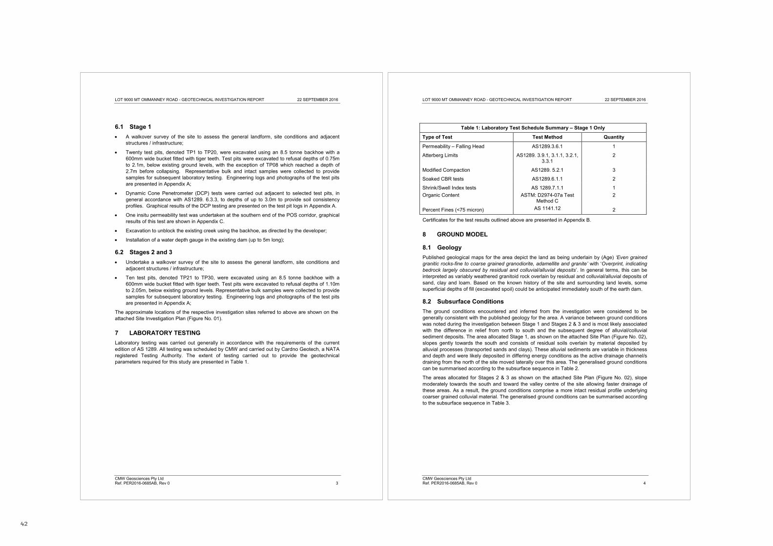
6.1 Stage 1 A walkover survey of the site to assess the general landform, site conditions and adjacentstructures / infrastructure;
Twenty test pits, denoted TP1 to TP20, were excavated using an 8.5 tonne backhoe with a600mm wide bucket fitted with tiger teeth. Test pits were excavated to refusal depths of 0.75mto 2.1m, below existing ground levels, with the exception of TP08 which reached a depth of2.7m before collapsing. Representative bulk and intact samples were collected to providesamples for subsequent laboratory testing. Engineering logs and photographs of the test pitsare presented in Appendix A;
Dynamic Cone Penetrometer (DCP) tests were carried out adjacent to selected test pits, ingeneral accordance with AS1289. 6.3.3, to depths of up to 3.0m to provide soil consistencyprofiles. Graphical results of the DCP testing are presented on the test pit logs in Appendix A.
One insitu permeability test was undertaken at the southern end of the POS corridor, graphicalresults of this test are shown in Appendix C.
Excavation to unblock the existing creek using the backhoe, as directed by the developer;
Installation of a water depth gauge in the existing dam (up to 5m long);
6.2 Stages 2 and 3 Undertake a walkover survey of the site to assess the general landform, site conditions andadjacent structures / infrastructure;
Ten test pits, denoted TP21 to TP30, were excavated using an 8.5 tonne backhoe with a600mm wide bucket fitted with tiger teeth. Test pits were excavated to refusal depths of 1.10mto 2.05m, below existing ground levels. Representative bulk samples were collected to providesamples for subsequent laboratory testing. Engineering logs and photographs of the test pitsare presented in Appendix A;
The approximate locations of the respective investigation sites referred to above are shown on the attached Site Plan (Figure No. 0 ).
7 LABORATORY TESTING Laboratory testing was carried out generally in accordance with the requirements of the current edition of AS 1289. All testing was scheduled by CMW and carried out by Cardno Geotech, a NATA registered Testing Authority. The extent of testing carried out to provide the geotechnical parameters required for this study are presented in Table 1.
LOT 9000 MT OMMANNEY ROAD - GEOTECHNICAL INVESTIGATION REPORT 22 SEPTEMBER 2016
CMW Geosciences Pty Ltd Ref. PER2016-0685AB, Rev 0 4
Table 1: Laboratory Test Schedule Summary – Stage 1 Only
Type of Test Test Method Quantity
Permeability – Falling Head AS1289.3.6.1 1
Atterberg Limits AS1289. 3.9.1, 3.1.1, 3.2.1, 3.3.1
2
Modified Compaction AS1289. 5.2.1 3
Soaked CBR tests AS1289.6.1.1 2
Shrink/Swell Index tests Organic Content Percent Fines (<75 micron)
AS 1289.7.1.1 ASTM: D2974-07a Test
Method C AS 1141.12
1 2 2
Certificates for the test results outlined above are presented in Appendix B.
8 GROUND MODEL
8.1 Geology Published geological maps for the area depict the land as being underlain by (Age) ‘Even grained granitic rocks-fine to coarse grained granodiorite, adamellite and granite’ with ‘Overprint, indicating bedrock largely obscured by residual and colluvial/alluvial deposits’. In general terms, this can be interpreted as variably weathered granitoid rock overlain by residual and colluvial/alluvial deposits of sand, clay and loam. Based on the known history of the site and surrounding land levels, some superficial depths of fill (excavated spoil) could be anticipated immediately south of the earth dam.
8.2 Subsurface Conditions The ground conditions encountered and inferred from the investigation were considered to be generally consistent with the published geology for the area. A variance between ground conditions was noted during the investigation between Stage 1 and Stages 2 & 3 and is most likely associated with the difference in relief from north to south and the subsequent degree of alluvial/colluvial sediment deposits. The area allocated Stage 1, as shown on the attached Site Plan (Figure No. 02), slopes gently towards the south and consists of residual soils overlain by material deposited by alluvial processes (transported sands and clays). These alluvial sediments are variable in thickness and depth and were likely deposited in differing energy conditions as the active drainage channel/s draining from the north of the site moved laterally over this area. The generalised ground conditions can be summarised according to the subsurface sequence in Table 2.
The areas allocated for Stages 2 & 3 as shown on the attached Site Plan (Figure No. 02), slope moderately towards the south and toward the valley centre of the site allowing faster drainage of these areas. As a result, the ground conditions comprise a more intact residual profile underlying coarser grained colluvial material. The generalised ground conditions can be summarised according to the subsurface sequence in Table 3.
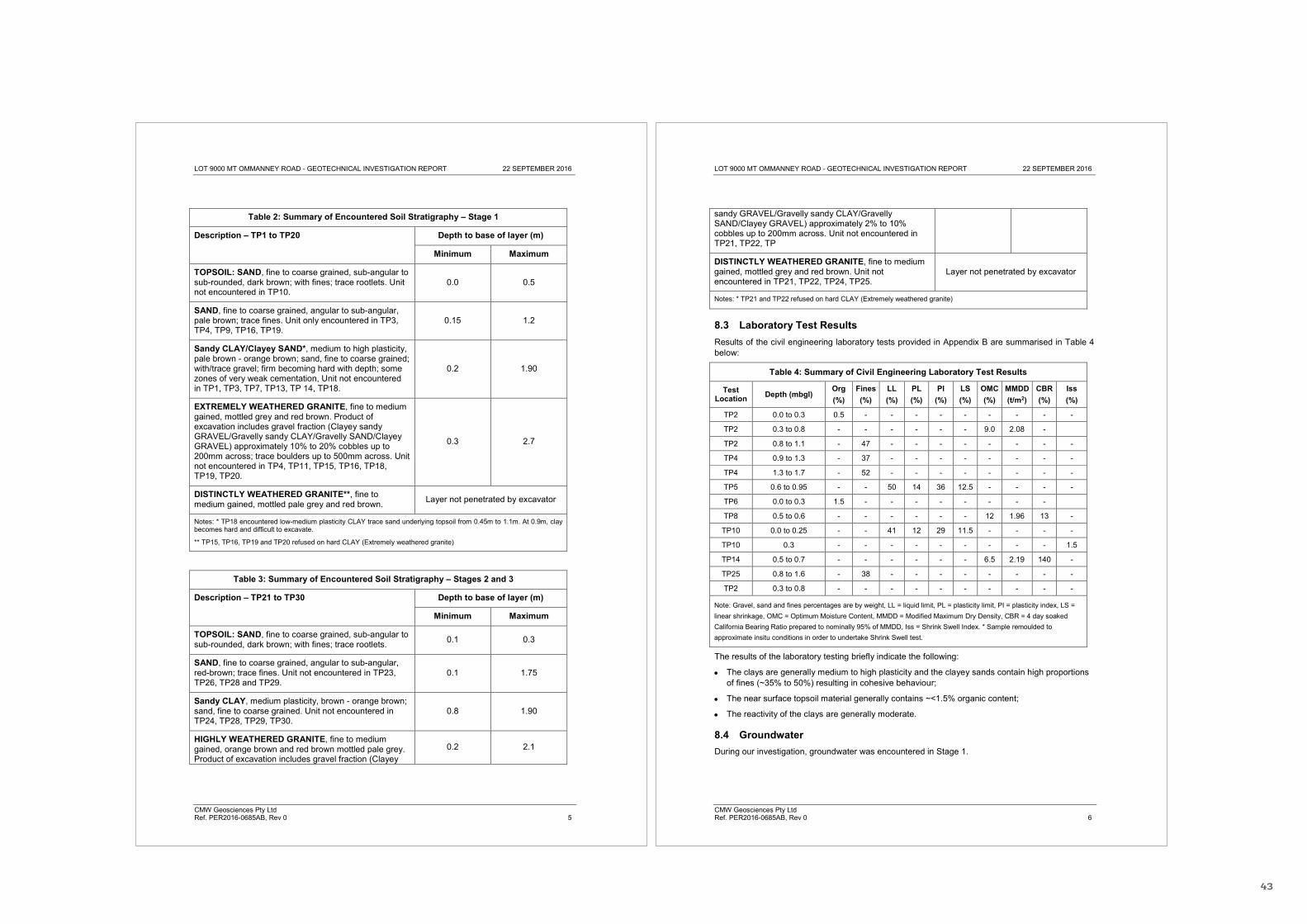
43
LOT 9000 MT OMMANNEY ROAD - GEOTECHNICAL INVESTIGATION REPORT 22 SEPTEMBER 2016
CMW Geosciences Pty Ltd Ref. PER2016-0685AB, Rev 0 5
Table 2: Summary of Encountered Soil Stratigraphy – Stage 1
Description – TP1 to TP20 Depth to base of layer (m)
Minimum Maximum
TOPSOIL: SAND, fine to coarse grained, sub-angular to sub-rounded, dark brown; with fines; trace rootlets. Unit not encountered in TP10.
0.0 0.5
SAND, fine to coarse grained, angular to sub-angular, pale brown; trace fines. Unit only encountered in TP3, TP4, TP9, TP16, TP19.
0.15 1.2
Sandy CLAY/Clayey SAND*, medium to high plasticity, pale brown - orange brown; sand, fine to coarse grained; with/trace gravel; firm becoming hard with depth; some zones of very weak cementation, Unit not encountered in TP1, TP3, TP7, TP13, TP 14, TP18.
0.2 1.90
EXTREMELY WEATHERED GRANITE, fine to medium gained, mottled grey and red brown. Product of excavation includes gravel fraction (Clayey sandy GRAVEL/Gravelly sandy CLAY/Gravelly SAND/Clayey GRAVEL) approximately 10% to 20% cobbles up to 200mm across; trace boulders up to 500mm across. Unit not encountered in TP4, TP11, TP15, TP16, TP18, TP19, TP20.
0.3 2.7
DISTINCTLY WEATHERED GRANITE**, fine to medium gained, mottled pale grey and red brown. Layer not penetrated by excavator
Notes: * TP18 encountered low-medium plasticity CLAY trace sand underlying topsoil from 0.45m to 1.1m. At 0.9m, clay becomes hard and difficult to excavate.
** TP15, TP16, TP19 and TP20 refused on hard CLAY (Extremely weathered granite)
Table 3: Summary of Encountered Soil Stratigraphy – Stages 2 and 3
Description – TP21 to TP30 Depth to base of layer (m)
Minimum Maximum
TOPSOIL: SAND, fine to coarse grained, sub-angular to sub-rounded, dark brown; with fines; trace rootlets. 0.1 0.3
SAND, fine to coarse grained, angular to sub-angular, red-brown; trace fines. Unit not encountered in TP23, TP26, TP28 and TP29.
0.1 1.75
Sandy CLAY, medium plasticity, brown - orange brown; sand, fine to coarse grained. Unit not encountered in TP24, TP28, TP29, TP30.
0.8 1.90
HIGHLY WEATHERED GRANITE, fine to medium gained, orange brown and red brown mottled pale grey. Product of excavation includes gravel fraction (Clayey
0.2 2.1
LOT 9000 MT OMMANNEY ROAD - GEOTECHNICAL INVESTIGATION REPORT 22 SEPTEMBER 2016
CMW Geosciences Pty Ltd Ref. PER2016-0685AB, Rev 0 6
sandy GRAVEL/Gravelly sandy CLAY/Gravelly SAND/Clayey GRAVEL) approximately 2% to 10% cobbles up to 200mm across. Unit not encountered in TP21, TP22, TP
DISTINCTLY WEATHERED GRANITE, fine to medium gained, mottled grey and red brown. Unit not encountered in TP21, TP22, TP24, TP25.
Layer not penetrated by excavator
Notes: * TP21 and TP22 refused on hard CLAY (Extremely weathered granite)
8.3 Laboratory Test Results Results of the civil engineering laboratory tests provided in Appendix B are summarised in Table 4 below:
Table 4: Summary of Civil Engineering Laboratory Test Results
Test Location Depth (mbgl)
Org (%)
Fines (%)
LL (%)
PL (%)
PI (%)
LS (%)
OMC (%)
MMDD (t/m2)
CBR (%)
Iss (%)
TP2 0.0 to 0.3 0.5 - - - - - - - - -
TP2 0.3 to 0.8 - - - - - - 9.0 2.08 -
TP2 0.8 to 1.1 - 47 - - - - - - - -
TP4 0.9 to 1.3 - 37 - - - - - - - -
TP4 1.3 to 1.7 - 52 - - - - - - - -
TP5 0.6 to 0.95 - - 50 14 36 12.5 - - - -
TP6 0.0 to 0.3 1.5 - - - - - - - -
TP8 0.5 to 0.6 - - - - - - 12 1.96 13 -
TP10 0.0 to 0.25 - - 41 12 29 11.5 - - - -
TP10 0.3 - - - - - - - - - 1.5
TP14 0.5 to 0.7 - - - - - - 6.5 2.19 140 -
TP25 0.8 to 1.6 - 38 - - - - - - - -
TP2 0.3 to 0.8 - - - - - - - - - -
Note: Gravel, sand and fines percentages are by weight, LL = liquid limit, PL = plasticity limit, PI = plasticity index, LS = linear shrinkage, OMC = Optimum Moisture Content, MMDD = Modified Maximum Dry Density, CBR = 4 day soaked California Bearing Ratio prepared to nominally 95% of MMDD, Iss = Shrink Swell Index. * Sample remoulded to approximate insitu conditions in order to undertake Shrink Swell test.
The results of the laboratory testing briefly indicate the following:
The clays are generally medium to high plasticity and the clayey sands contain high proportions of fines (~35% to 50%) resulting in cohesive behaviour;
The near surface topsoil material generally contains ~<1.5% organic content;
The reactivity of the clays are generally moderate.
8.4 Groundwater During our investigation, groundwater was encountered in Stage 1.

44
LOT 9000 MT OMMANNEY ROAD - GEOTECHNICAL INVESTIGATION REPORT 22 SEPTEMBER 2016
CMW Geosciences Pty Ltd Ref. PER2016-0685AB, Rev 0 7
An existing earth dam was observed in the central northern portion of Stage 1. Historical aerial photography indicates that very shallow water remains ponded in the basin for an extended period during the wetter months of the year. Anecdotal evidence suggests that the dam has not held significant amounts of water for approximately 20 years. Groundwater was encountered in TP3, TP7, TP14 and HA1 in the southwestern portion of Stage 1 within granular layers (Gravelly SAND/Sandy Gravel/SAND) at depths between 1.0m and 1.6m indicating subterranean groundwater movement within a confined granular stratum. Perched water over the surficial clay soils must be anticipated following periods of rainfall.
8.5 Permeability The result of the insitu falling head permeability test carried out in the southern portion of Stage 1 were used to estimate the soil coefficient of permeability in accordance with the methods described in Horslev (1951). Table 5 below summarises the result obtained.
Table 5: Summary of In-situ Falling Head Permeability Test
Standpipe Screen Depth (mbgl)
Screened Formation
Test Method Approximate Permeability
(m/sec) (m/day)
HA01 0.0 to 0.55 CLAY/Sandy CLAY Horslev (1951) 8.21 x 10⁻⁷ 0.07
The laboratory permeability test was undertaken on a remoulded sample compacted to 95% MMDD in order to assess permeability of earthworked materials such as swales/drains and basins. The result of the test indicated a permeability of 4 x 10⁻⁸ m/s (0.0035 m/day).
9 GEOTECHNICAL ASSESSMENT AND RECOMMENDATIONS – STAGE 1
9.1 Uncontrolled Fill Uncontrolled Fill (presumably excavated spoil from the construction of the earth dam) was encountered immediately south of the dam within the central portion of the site to depths of up to 2.7m below ground level. Due to its uncontrolled nature the fill is considered susceptible to excessive settlement under design foundation loads.
9.2 Earthworks Relatively shallow cut and fill depths are anticipated along roadways and carparks, with negligible earthworks in field plot areas. Recommendations associated with this work are summarised as follows:
All vegetation or deleterious materials within proposed building envelopes and roadways must be stripped and stockpiled. Any tree stumps must be grubbed out and stockpiled. These materials are suitable for landscaping purposes only. Based on our organic content testing, the near surface material contains <1.5% organic content and may be blended and re-used on site subject to additional testing and likely blend materials;
Surficial soil and highly weathered granite materials (Table 2 & 3) can be readily excavated using conventional earthmoving plant. During the investigation, the 8.5 ton backhoe refused on the underlying granite and hard saprolitic clays overlying granite. A rock breaker or larger machinery may be required to excavate beyond test pit refusal depths which ranged from 0.75m to 2.1m;
LOT 9000 MT OMMANNEY ROAD - GEOTECHNICAL INVESTIGATION REPORT 22 SEPTEMBER 2016
CMW Geosciences Pty Ltd Ref. PER2016-0685AB, Rev 0 8
At the completion of excavation to design subgrade levels for slabs and pavement areas including foundation excavations, the exposed subgrade must be moisture conditioned and compacted (proof rolled) to achieve at least 95% compaction with respect to Modified Maximum Dry Density (MMDD). Any loose / soft, weak or organic materials observed during this proof roll shall be removed and replaced with compacted clean fill;
The shear strength of clay materials exposed in footing excavations must be verified using a DCP, where a blow count in excess of 4 per 100mm is considered to indicate adequate shear strength of the soil. Any soft areas must be excavated and replaced with either lean mix concrete or compacted clay fill. Measures must be taken to limit moisture changes where clay is exposed in any excavations. Footings should be poured soon after excavation to limit the potential for excessive moisture change;
Both cohesive and granular fill materials may be used for earthworks at the site. Granular fill must have less than 30% particles smaller than 0.075mm and a maximum particle size of 75mm. Cohesive fills must have a maximum particle size of 75mm and a liquid limit no greater than 50%. All fill materials must be free of organic or deleterious inclusions. It is considered that the granular and cohesive soils underlying the surficial topsoil are suitable for reuse as fill;
Fill materials must be placed in layers not exceeding either 200mm for cohesive materials and 300mm for granular materials. Fill must be moisture conditioned to ± 3% of optimum moisture content, placed and compacted to achieve a dry density ratio of at least 95% of Modified compaction (AS1289.5.2.1). Nuclear density meter testing is recommended to confirm the target density has been achieved, and;
The cohesive nature of the site soils will determine that they are susceptible to softening when wet and will be subject to cracking and deterioration where exposed to drying for any period of time. Therefore, across slab areas, consideration to the over-excavation and placement of a wearing course of crushed rock or similar should be made following subgrade compaction.
The technical and control requirements for Engineered Fill, including site observation and compaction testing, are outlined in AS3798. We recommend that this work, and in particular, determining the depth and extent of any Uncontrolled Fill removal during site earthworks, is completed under the direction and control of a suitably experienced Geotechnical Engineer/Engineering Geologist familiar with the contents of this report. CMW would be pleased to perform this function if required.
9.3 Site Classification – Stage 1 A Class M site classification to AS2870, with between 20mm and 40mm of ground movement due to seasonal moisture changes is recommended subject to the foundation preparation recommendations provided herein.
This Class M site classification may be revised to a Class S if no less than 0.8m of granular fill is placed over the cohesive subgrade. Granular fill placed for the purposes of improving site classification must have no more than 12% fines (particles < 0.075mm) and be compacted as per Section 9.2.
9.3.1 Preliminary Site Classification - Stages 2 & 3
A Class M site classification is anticipated for Stages 2 & 3 based on results of the test pitting, though this classification will need verification subject to further investigation and laboratory testing.
9.4 Strip and Pad Foundations The design of available foundation bearing pressures for strip and pad footings at this site has been carried out using the Terzaghi bearing capacity equation. Subject to completing the earthworks and

45
LOT 9000 MT OMMANNEY ROAD - GEOTECHNICAL INVESTIGATION REPORT 22 SEPTEMBER 2016
CMW Geosciences Pty Ltd Ref. PER2016-0685AB, Rev 0 9
foundation preparation recommendations provided herein, shallow strip or pad footings founded within very stiff to hard cohesive soils may be designed on the basis of the maximum allowable bearing pressures provided in Table 6 below:
Table 6: Summary of Shallow Footing Design Bearing Pressure
Embedment Depth (m)
Footing Width (m)
Footing Length (m)
Allowable Bearing Pressure (kPa)
0.5
0.5 strip 350
1.0 strip 300
1.0 1.0 350
These values are based on a geotechnical strength reduction factor of 0.5 and an average load factor of 1.5 (Factor of Safety = 3.0). It should be noted that these bearing pressures assume isolated, vertical, non-eccentric loads. Note that embedment of shallow pad foundations is critical to ensure they are note effected by seasonal wetting and drying.
Subject to the earthworks and foundation preparation works being undertaken as described herein, it has been calculated that the total settlement of the footing configurations and design pressures outlined in Table 6 above are unlikely to exceed approximately 20mm to 25mm. Differential settlements are unlikely to exceed approximately one half of these values.
9.5 Earth Retention Design parameters for retaining walls are summarised as follows:
Table 7: Retaining Wall Design Parameters
Soil Unit (kN/m3)
Ø’ (deg)
K0 E’ (MPa)
No wall friction Wall friction = 2/3Ø
Ka Kp Ka Kp
Clay / sandy clay / clayey sand 18 28 0.53 20 0.36 2.77 0.32 5.15
Notes: 1. Refer to Table 2 for definition of soil unit levels 2. – soil unit weight; Ø’ - angle of internal soil friction; K0 - coefficient of earth pressure at rest, Ka -
coefficient of active earth pressure, Kp - coefficient of passive earth pressure; E’ – long term Young’s modulus.
3. Values of K0 are based on initial conditions following construction of the perimeter retention system. 4. The retaining wall designer must adopt the above set of Ka and Kp parameters relevant to the actual
construction method adopted 5. The above parameters are based on the condition of a horizontal ground surface behind the retaining
structure. Applicable surcharge loads behind the wall must also be considered in the design.
Retaining structures should be designed in accordance with AS 4678-2002 “Earth Retaining Structures” or an alternate approved factor of safety approach. The compaction equipment used to compact backfill behind retaining walls must be carefully selected and preferably light-weight compaction equipment should be used. The load on the retaining wall due to compaction equipment may be estimated from Figure J5 in AS4678-2002 “Earth Retaining Structures”.
LOT 9000 MT OMMANNEY ROAD - GEOTECHNICAL INVESTIGATION REPORT 22 SEPTEMBER 2016
CMW Geosciences Pty Ltd Ref. PER2016-0685AB, Rev 0 10
It is noted that some ground movement will occur behind temporary or permanent retaining walls. By definition, movement of the wall must occur to fully mobilise the active and passive earth pressure coefficients provided in Table 6 above. The extent of this movement is dependent on the height of retaining, type of wall selected and construction methodology. This must be considered during the design and construction of the retaining walls to ensure adjacent facilities are not adversely affected.
9.6 Drainage The insitu permeability result (0.07 m/day) indicate that site is unsuitable for the practical use of in ground soakage systems (soak wells) to dispose of stormwater from the proposed development.
The laboratory permeability test result (0.0035 m/day) may be used for design purposes of earthworked cohesive material in swales/drains.
9.7 Pavements – Stage 1 Based on the in-situ and laboratory test results across Stage 1, it is recommended that pavements be designed on the basis of the following CBR values:
A CBR of 2% for clay soil over the larger portion of the site; A CBR of 8% for clayey sands; and
Compacted granular fill (Section 9.2) may be used as a select subgrade fill to calculate a higher design subgrade CBR values. Either Figure 8 of Engineering Road Note 9 (for an empirical design approach) or Section 8.2.2 of Austroads Part 2: Pavement Structural design (for a mechanistic design approach) may be used. Depending on the design approach and traffic load, a granular fill thickness of nominally 500mm to 600mm over clay soil could justify the use of a subgrade CBR of up to 12%.
This design CBR value is subject to the exposed subgrade being moisture conditioned and compacted in accordance with the recommendations provided in Section 9.2. It is recommended that QA / QC testing be undertaken on subgrade materials during construction.
The results of the laboratory CBR testing indicate that the granular materials encountered during the test pitting may be suitable for use as select subgrade fill, however, additional testing would be required in order to confirm this.
10 FURTHER WORK Depending on final development details and, specifically, bulk earthworks plans it may be beneficial to undertake further investigation to confirm specific subgrade conditions in relevant areas (road alignments, for example).
In addition, CMW has extensive experience in the testing, observation and monitoring of earthworks programs, and would be pleased to undertake this work for the project.
11 CLOSURE The findings contained within this report are the result of limited discrete investigations conducted in accordance with normal practices and standards. To the best of our knowledge, they represent a reasonable interpretation of the general condition of the site. Under no circumstances, can it be considered that these findings represent the actual state of the ground conditions away from our investigation locations.
46
LOT 9000 MT OMMANNEY ROAD - GEOTECHNICAL INVESTIGATION REPORT 22 SEPTEMBER 2016
CMW Geosciences Pty Ltd Ref. PER2016-0685AB, Rev 0 11
If the ground conditions encountered during construction are significantly different from those described in this report and on which the conclusions and recommendations were based, then we must be notified immediately.
This report has been prepared for use by H & H Developments in relation to Lot 9000 Mt Ommanney Road project in accordance with generally accepted consulting practice. No other warranty, expressed or implied, is made as to the professional advice included in this report. Use of this report by parties other than H & H Developments and their respective consultants and contractors is at their risk as it may not contain sufficient information for any other purposes.
For and on behalf of CMW Geosciences Pty Ltd
Dave Pearce Philip Mather Engineering Geologist Principal Engineering Geologist Distribution: 1 copy to H & H Developments (electronic)
Original held by CMW Geosciences Pty Ltd
LOT 9000 MT OMMANNEY ROAD - GEOTECHNICAL INVESTIGATION REPORT 22 SEPTEMBER 2016
CMW Geosciences Pty Ltd Ref. PER2016-0685AB, Rev 0 12
12 REFERENCES
AS 1289, Methods of testing soils for engineering purposes, Standards Australia, Sydney AS 1726 (inc. amendments 1 & 2), Geotechnical Site Investigations, Standards Australia,
Sydney, 1993 AS 2870, Residential slabs and footings, Standards Australia, Sydney, 2011 AS 3798 (inc. amendment 1), Guidelines on earthworks for commercial and residential
developments, Standards Australia, Sydney, 2007 AS 4678 (inc. amendments 1 & 2), Earth retaining structures, Standards Australia, Sydney,
2002 Perth, 1:250,000 Sheet 50-14 and part of 50-13, Zone 1 Australia Series, Geological Survey
of Western Australia, 1978 Terzaghi, K. (1943). Theoretical soil mechanics. 1st ed. New York: J. Wiley and Sons, Inc.
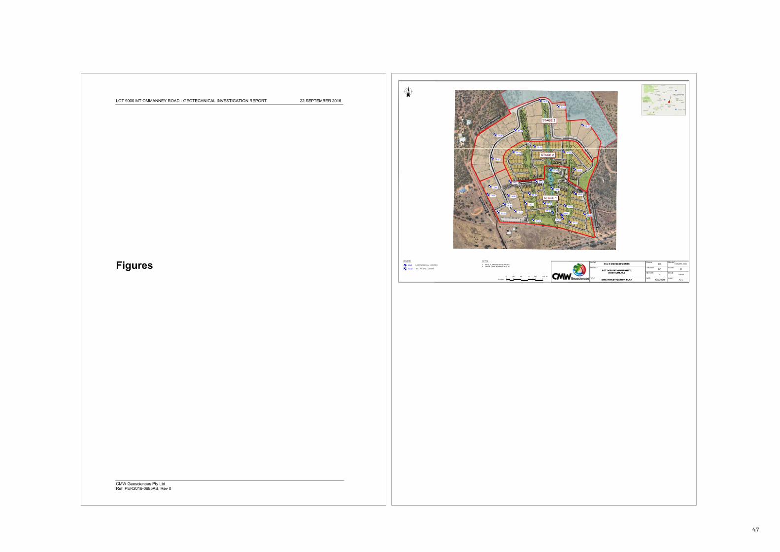
47
LOT 9000 MT OMMANNEY ROAD - GEOTECHNICAL INVESTIGATION REPORT 22 SEPTEMBER 2016
CMW Geosciences Pty Ltd Ref. PER2016-0685AB, Rev 0
Figures
TP-01
TP-15
TP-11
TP-12
TP-18
TP-13
TP-19
TP-05
TP-08TP-04
TP-03 TP-02
TP-10
TP-09
TP-20
TP-16
TP-06
TP-17
TP-07
TP-14
TP-30
TP-26
TP-22
TP-23
TP-28
TP-25
TP-27
TP-24
TP-29
TP-21
HA01
CLIENT:
PROJECT:
TITLE:
DRAWN:
SCALE:
PROJECT:
DATE:
REVISION:
FIGURE:CHECKED:
SHEET:
H & H DEVELOPMENTS
LOT 9000 MT OMMANNEY,NORTHAM, WA
SITE INVESTIGATION PLAN
DE PER2016-0685
12/09/2016
DP 01
0 1:4000
A3 L
HA01
TP-01
HAND AUGER (HA) LOCATION
TEST PIT (TP) LOCATION
LEGEND:
1. BASE PLAN ADAPTED SUPPLIED2. IMAGE FROM NEARMAP 06.01.10
NOTES:
0 80 120 160 200 m40
1:4000
SITE LOCATION
