north central rec engineering...
TRANSCRIPT
energysolutions… to power your future
Transformer 101Design Issues
David L. Harris, P.E. Douglas ReedCustomer Technical Executive Senior Design EngineerOffice: 262-547-0121 Office: 262-547-0121 Email: Email: [email protected] [email protected]
North Central REC Engineering Conference
Duluth, MinnesotaMarch 8, 2006
energysolutions… to power your future
energysolutions… to power your future
• IEEE/ANSI Standards• Transformer Design Topics
• Impedance• AMBIENT• ALTITUDE• OPERATIONAL ISSUES• NOMINAL VOLTAGES/OVER EXCITATION• ACCESSORIES• OIL PRESERVATION SYSTEMS• TAP CHANGERS• SERIES PARALLEL OPERATION• MINIMUM DESIGN BASICS
energysolutions… to power your future
ANSI/IEEECURRENT Standards
energysolutions… to power your future
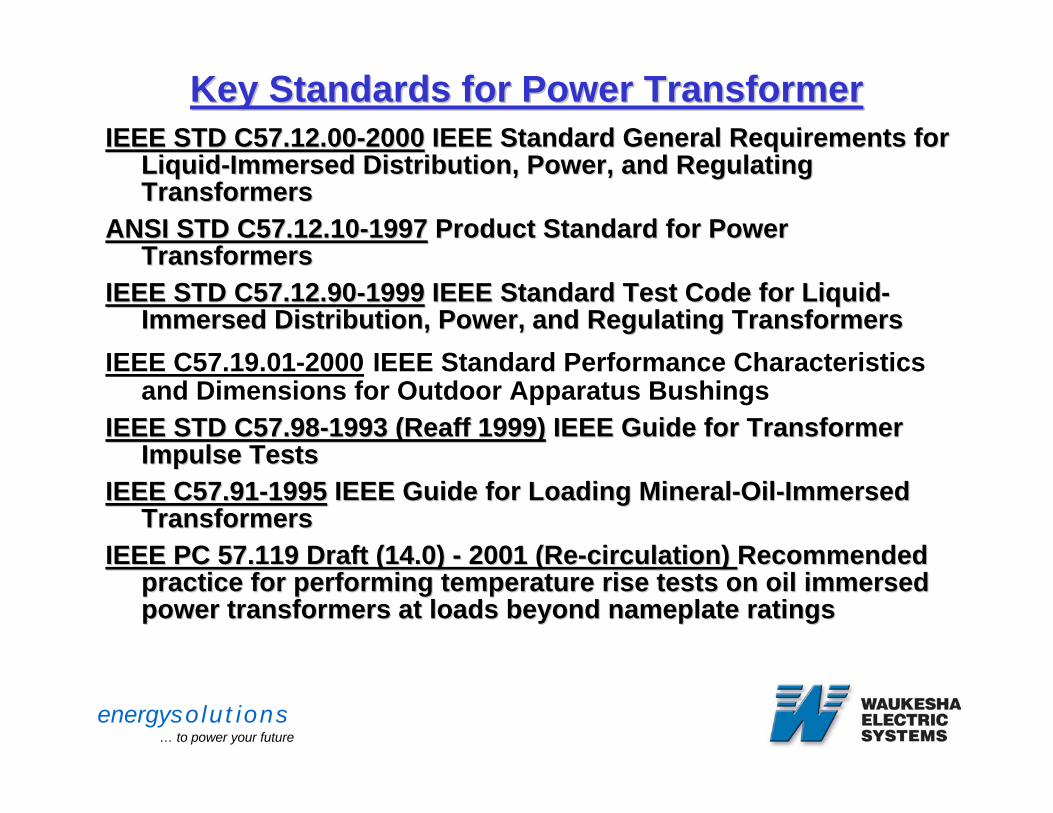
Key Standards for Power TransformerKey Standards for Power TransformerIEEE STD C57.12.00IEEE STD C57.12.00--20002000 IEEE Standard General Requirements for IEEE Standard General Requirements for
LiquidLiquid--Immersed Distribution, Power, and Regulating Immersed Distribution, Power, and Regulating TransformersTransformers
ANSI STD C57.12.10ANSI STD C57.12.10--19971997 Product Standard for Power Product Standard for Power TransformersTransformers
IEEE STD C57.12.90IEEE STD C57.12.90--19991999 IEEE Standard Test Code for LiquidIEEE Standard Test Code for Liquid--Immersed Distribution, Power, and Regulating TransformersImmersed Distribution, Power, and Regulating Transformers
IEEE C57.19.01-2000 IEEE Standard Performance Characteristics and Dimensions for Outdoor Apparatus Bushings
IEEE STD C57.98IEEE STD C57.98--1993 (1993 (ReaffReaff 1999)1999) IEEE Guide for Transformer IEEE Guide for Transformer Impulse TestsImpulse Tests
IEEE C57.91IEEE C57.91--19951995 IEEE Guide for Loading MineralIEEE Guide for Loading Mineral--OilOil--Immersed Immersed TransformersTransformers
IEEE PC 57.119 Draft (14.0) IEEE PC 57.119 Draft (14.0) -- 2001 (Re2001 (Re--circulation) circulation) Recommended Recommended practice for performing temperature rise tests on oil immersed practice for performing temperature rise tests on oil immersed power transformers at loads beyond nameplate ratingspower transformers at loads beyond nameplate ratings
energysolutions… to power your future
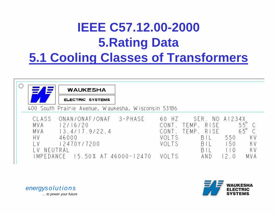
IEEE C57.12.00-20005.Rating Data
5.1 Cooling Classes of Transformers
energysolutions… to power your future
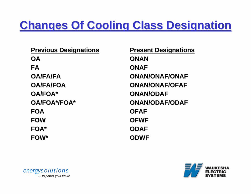
Changes Of Cooling Class DesignationChanges Of Cooling Class Designation
Previous DesignationsPrevious DesignationsOAOAFAFAOA/FA/FAOA/FA/FAOA/FA/FOAOA/FA/FOAOA/FOA*OA/FOA*OA/FOA*/FOA*OA/FOA*/FOA*FOAFOAFOWFOWFOA*FOA*FOW*FOW*
Present DesignationsPresent DesignationsONANONANONAFONAFONAN/ONAF/ONAFONAN/ONAF/ONAFONAN/ONAF/OFAFONAN/ONAF/OFAFONAN/ODAFONAN/ODAFONAN/ODAF/ODAFONAN/ODAF/ODAFOFAFOFAFOFWFOFWFODAFODAFODWFODWF
energysolutions… to power your future
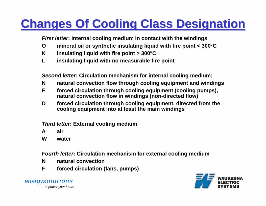
Changes Of Cooling Class DesignationChanges Of Cooling Class DesignationFirst letter: Internal cooling medium in contact with the windingsO mineral oil or synthetic insulating liquid with fire point < 300°CK insulating liquid with fire point > 300°CL insulating liquid with no measurable fire point
Second letter: Circulation mechanism for internal cooling medium:N natural convection flow through cooling equipment and windingsF forced circulation through cooling equipment (cooling pumps),
natural convection flow in windings (non-directed flow) D forced circulation through cooling equipment, directed from the
cooling equipment into at least the main windings
Third letter: External cooling medium A airW water
Fourth letter: Circulation mechanism for external cooling mediumN natural convectionF forced circulation (fans, pumps)
energysolutions… to power your future
Transformer Design Topics
energysolutions… to power your future
Impedance (Leakage Reactance)
energysolutions… to power your future
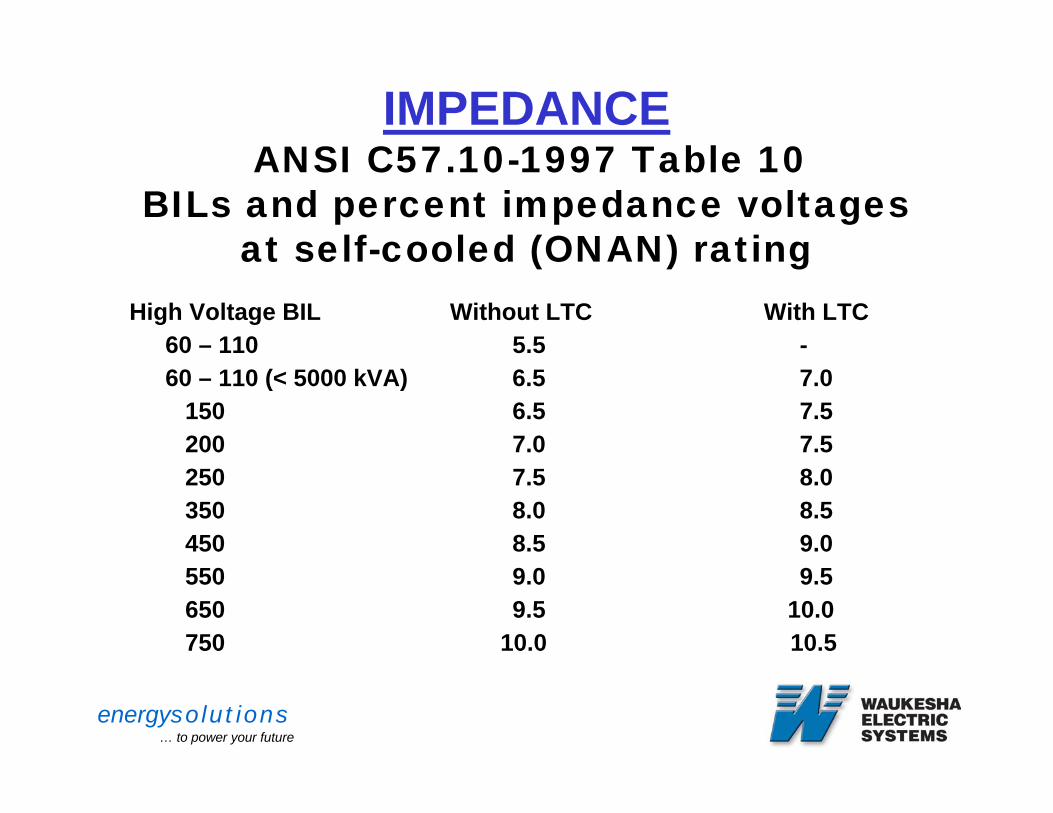
IMPEDANCEANSI C57.10-1997 Table 10
BILs and percent impedance voltages at self-cooled (ONAN) rating
High Voltage BIL Without LTC With LTC60 – 110 5.5 -60 – 110 (< 5000 kVA) 6.5 7.0
150 6.5 7.5200 7.0 7.5250 7.5 8.0350 8.0 8.5450 8.5 9.0550 9.0 9.5650 9.5 10.0750 10.0 10.5
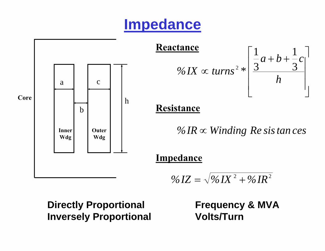
Impedance
ca
bh
⎥⎥⎥
⎦
⎤
⎢⎢⎢
⎣
⎡ ++∝
h
cba*turnsIX% 3
131
2
cestansisReWindingIR% ∝
22 IR%IX%IZ% +=
Reactance
Resistance
Impedance
Core
Inner Wdg
Outer Wdg
Directly Proportional Frequency & MVA Inversely Proportional Volts/Turn
energysolutions… to power your future
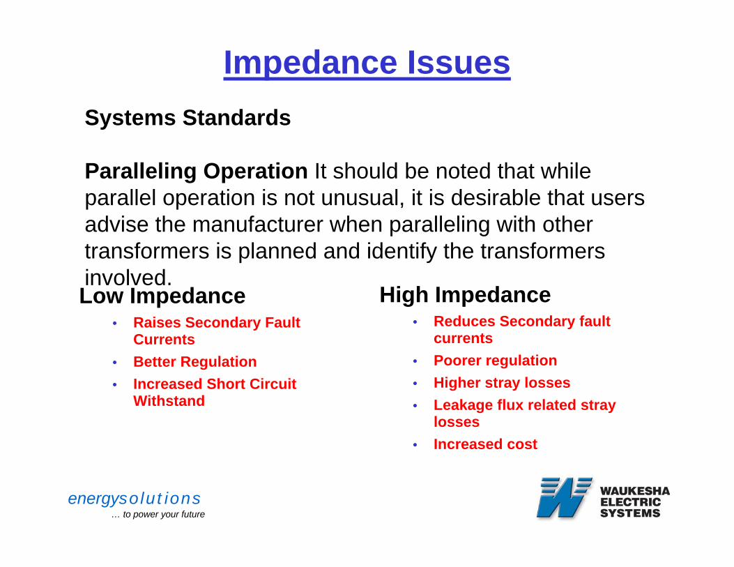
Impedance Issues
Low Impedance• Raises Secondary Fault
Currents• Better Regulation• Increased Short Circuit
Withstand
High Impedance• Reduces Secondary fault
currents• Poorer regulation • Higher stray losses• Leakage flux related stray
losses • Increased cost
Systems Standards
Paralleling Operation It should be noted that while parallel operation is not unusual, it is desirable that users advise the manufacturer when paralleling with other transformers is planned and identify the transformers involved.
energysolutions… to power your future
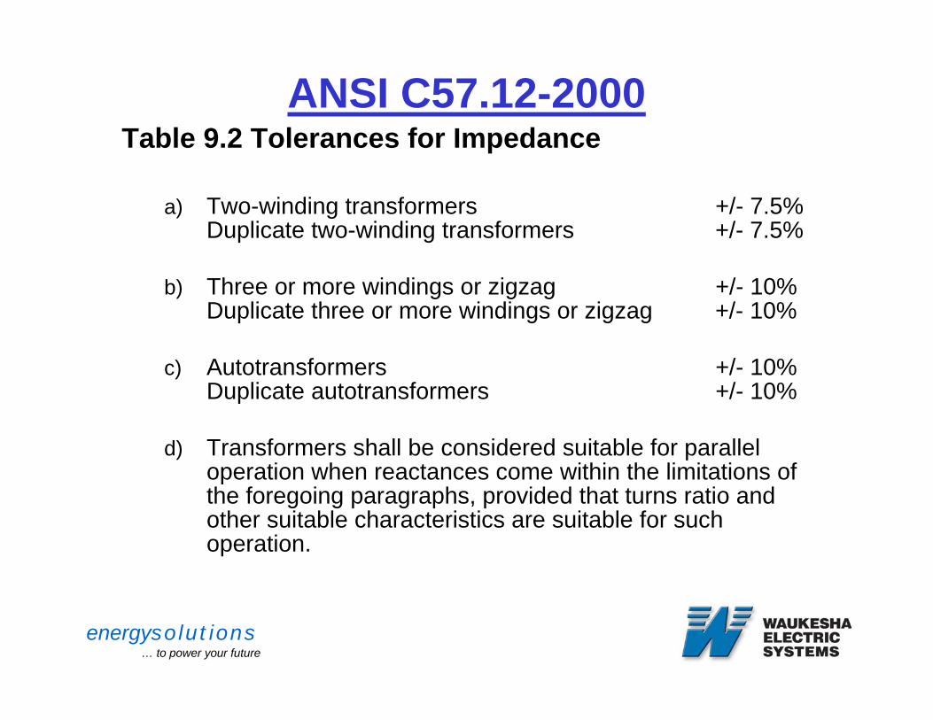
ANSI C57.12-2000Table 9.2 Tolerances for Impedance
a) Two-winding transformers +/- 7.5%Duplicate two-winding transformers +/- 7.5%
b) Three or more windings or zigzag +/- 10%Duplicate three or more windings or zigzag +/- 10%
c) Autotransformers +/- 10%Duplicate autotransformers +/- 10%
d) Transformers shall be considered suitable for parallel operation when reactances come within the limitations of the foregoing paragraphs, provided that turns ratio and other suitable characteristics are suitable for such operation.
energysolutions… to power your future
DESIGN TOPICS
• AMBIENT• ALTITUDE• NOMINAL VOLTAGES• OVER EXCITATION• SERIES PARALLEL OPERATION• MINIMUM DESIGN BASICS
energysolutions… to power your future
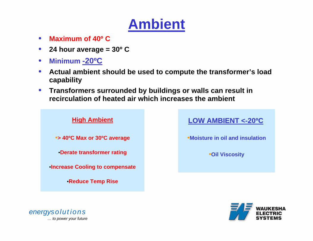
Ambient• Maximum of 40º C• 24 hour average = 30º C • Minimum -20ºC• Actual ambient should be used to compute the transformer’s load
capability• Transformers surrounded by buildings or walls can result in
recirculation of heated air which increases the ambient
High Ambient
•> 40ºC Max or 30ºC average
•Derate transformer rating
•Increase Cooling to compensate
•Reduce Temp Rise
LOW AMBIENT <-20ºC
•Moisture in oil and insulation
•Oil Viscosity
energysolutions… to power your future
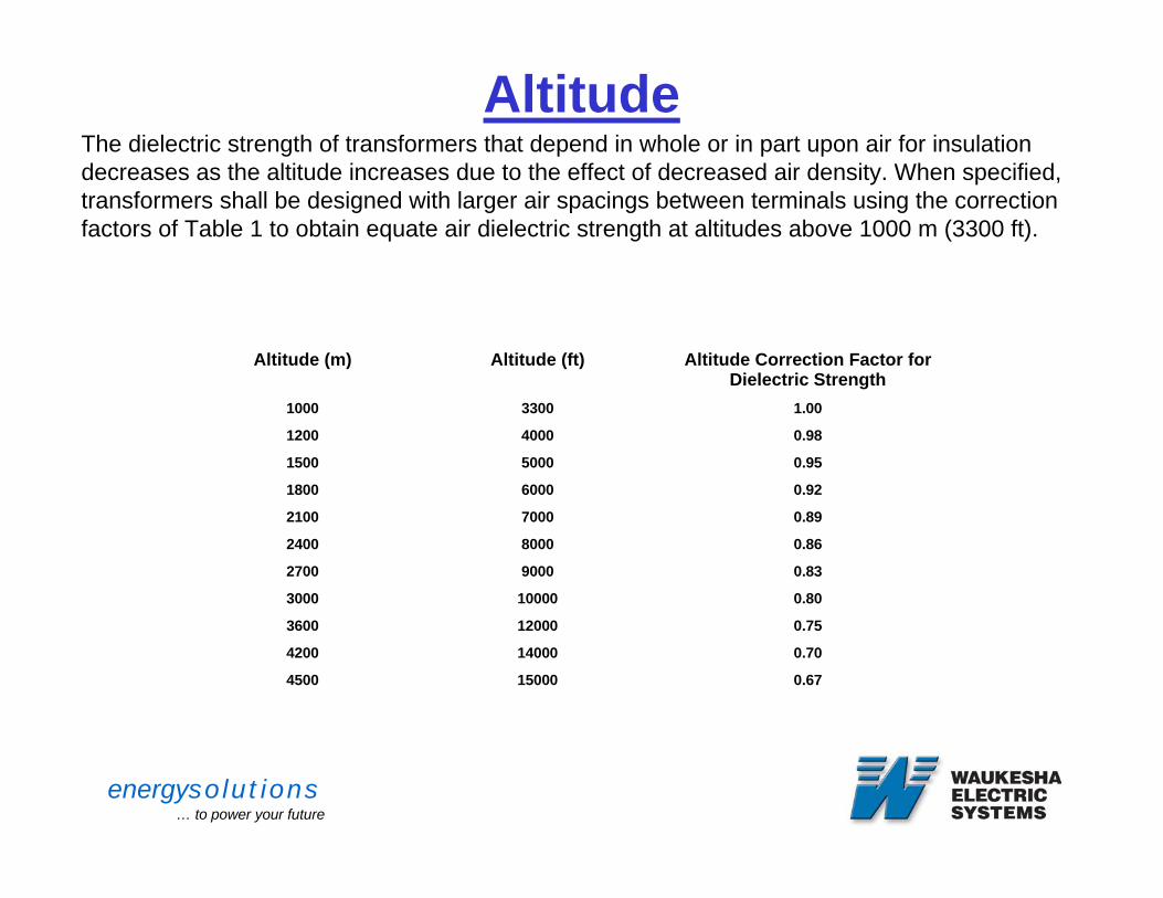
AltitudeThe dielectric strength of transformers that depend in whole or in part upon air for insulation decreases as the altitude increases due to the effect of decreased air density. When specified, transformers shall be designed with larger air spacings between terminals using the correction factors of Table 1 to obtain equate air dielectric strength at altitudes above 1000 m (3300 ft).
Table 1 – Dielectric strength correction factors for altitudes greater that 1000 m (3300 ft)
0.67150004500
0.70140004200
0.75120003600
0.80100003000
0.8390002700
0.8680002400
0.8970002100
0.9260001800
0.9550001500
0.9840001200
1.0033001000
Altitude Correction Factor for Dielectric Strength
Altitude (ft)Altitude (m)
NOTE - An altitude of 4500 m (15,000 ft) is considered a maximum for transformers conforming to this standard.
energysolutions… to power your future
Normal Operation
• Step Down Operation• Step-up Operation
GSUs• Reverse Power Flow (Step-up)• Auto Transformers require additional
design consideration.
energysolutions… to power your future
Generator Step Up Transformers
• Wye - Delta
• Overexcitation
• Voltage Regulation considerations
• Breaker Protection
energysolutions… to power your future
Nominal Voltage
• 67 kV vs 69 kV• 12.47 vs 13.09 or 13.2 kV• Transformer supplier assumes that the
transmission line voltage is the nominal voltage
energysolutions… to power your future
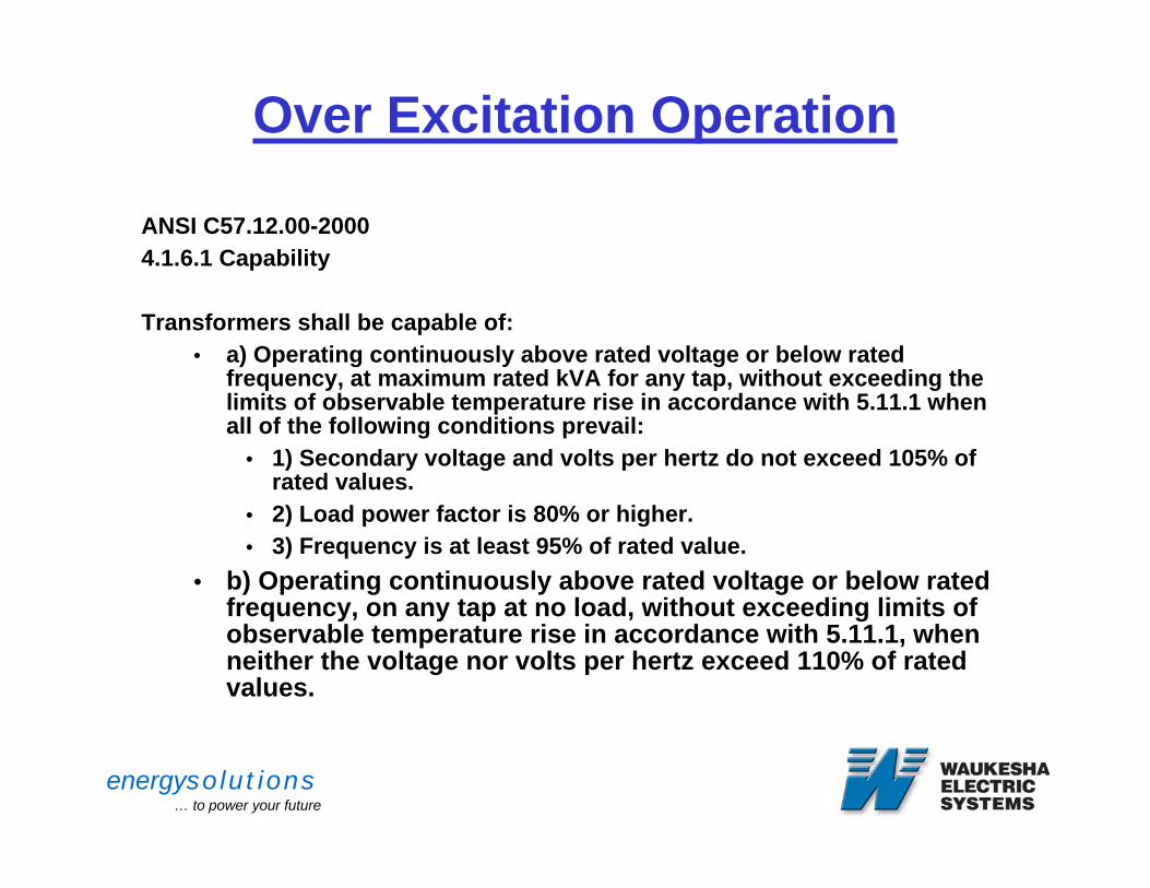
Over Excitation Operation
ANSI C57.12.00-20004.1.6.1 Capability
Transformers shall be capable of:• a) Operating continuously above rated voltage or below rated
frequency, at maximum rated kVA for any tap, without exceeding the limits of observable temperature rise in accordance with 5.11.1 when all of the following conditions prevail:
• 1) Secondary voltage and volts per hertz do not exceed 105% of rated values.
• 2) Load power factor is 80% or higher.• 3) Frequency is at least 95% of rated value.
• b) Operating continuously above rated voltage or below rated frequency, on any tap at no load, without exceeding limits of observable temperature rise in accordance with 5.11.1, when neither the voltage nor volts per hertz exceed 110% of rated values.
energysolutions… to power your future
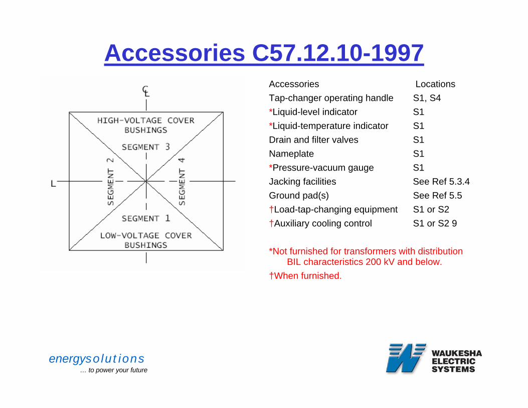
Accessories C57.12.10-1997Accessories Locations Tap-changer operating handle S1, S4 *Liquid-level indicator S1 *Liquid-temperature indicator S1 Drain and filter valves S1 Nameplate S1 *Pressure-vacuum gauge S1 Jacking facilities See Ref 5.3.4Ground pad(s) See Ref 5.5†Load-tap-changing equipment S1 or S2 †Auxiliary cooling control S1 or S2 9
*Not furnished for transformers with distribution BIL characteristics 200 kV and below.
†When furnished.
NOTE—Some designs include accessories and wiring connections as part of the load-tap-changing equipment assembly. When this is the case, accessories may be located in the same segment as the load tap changer and may be viewed parallel to the segment centerline.
Figure 1 – Accessories
energysolutions… to power your future
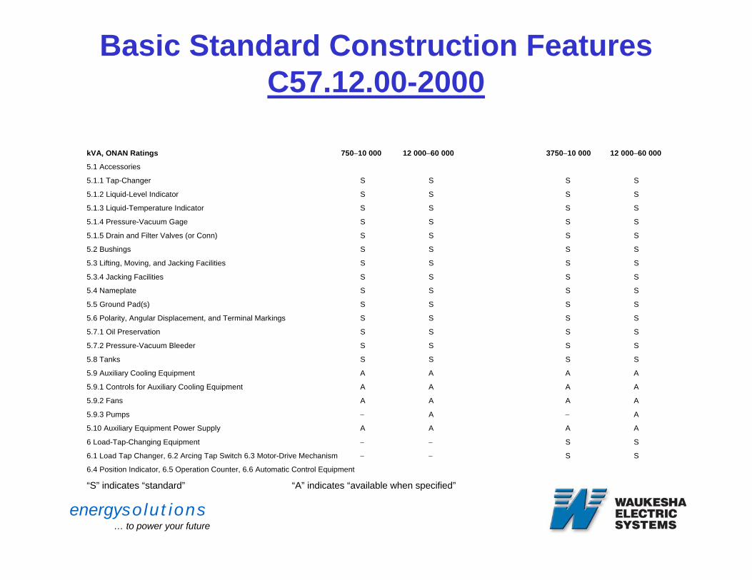
Basic Standard Construction Features C57.12.00-2000
Table 11 – “Basic standard” Power Class BILs construction features
__Without Load Tap Changing__ ___With Load Tap Changing___
kVA, ONAN Ratings 750−10 000 12 000−60 000 3750−10 000 12 000−60 000
5.1 Accessories
5.1.1 Tap-Changer S S S S
5.1.2 Liquid-Level Indicator S S S S
5.1.3 Liquid-Temperature Indicator S S S S
5.1.4 Pressure-Vacuum Gage S S S S
5.1.5 Drain and Filter Valves (or Conn) S S S S
5.2 Bushings S S S S
5.3 Lifting, Moving, and Jacking Facilities S S S S
5.3.4 Jacking Facilities S S S S
5.4 Nameplate S S S S
5.5 Ground Pad(s) S S S S
5.6 Polarity, Angular Displacement, and Terminal Markings S S S S
5.7.1 Oil Preservation S S S S
5.7.2 Pressure-Vacuum Bleeder S S S S
5.8 Tanks S S S S
5.9 Auxiliary Cooling Equipment A A A A
5.9.1 Controls for Auxiliary Cooling Equipment A A A A
5.9.2 Fans A A A A
5.9.3 Pumps − A − A
5.10 Auxiliary Equipment Power Supply A A A A
6 Load-Tap-Changing Equipment − − S S
6.1 Load Tap Changer, 6.2 Arcing Tap Switch 6.3 Motor-Drive Mechanism − − S S
6.4 Position Indicator, 6.5 Operation Counter, 6.6 Automatic Control Equipment
“S” indicates “standard” “A” indicates “available when specified”
energysolutions… to power your future
Core Grounds
• Standard – Near an access cover Removable for testingCaptive Hardware
• External – Brought out through a bushing
• Series Transformers
energysolutions… to power your future
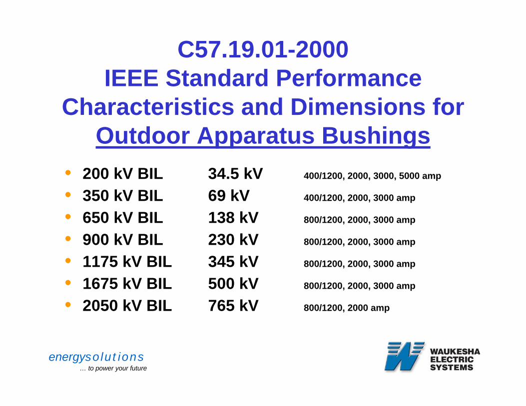
C57.19.01-2000IEEE Standard Performance
Characteristics and Dimensions for Outdoor Apparatus Bushings
• 200 kV BIL 34.5 kV 400/1200, 2000, 3000, 5000 amp
• 350 kV BIL 69 kV 400/1200, 2000, 3000 amp
• 650 kV BIL 138 kV 800/1200, 2000, 3000 amp
• 900 kV BIL 230 kV 800/1200, 2000, 3000 amp
• 1175 kV BIL 345 kV 800/1200, 2000, 3000 amp
• 1675 kV BIL 500 kV 800/1200, 2000, 3000 amp
• 2050 kV BIL 765 kV 800/1200, 2000 amp
energysolutions… to power your future
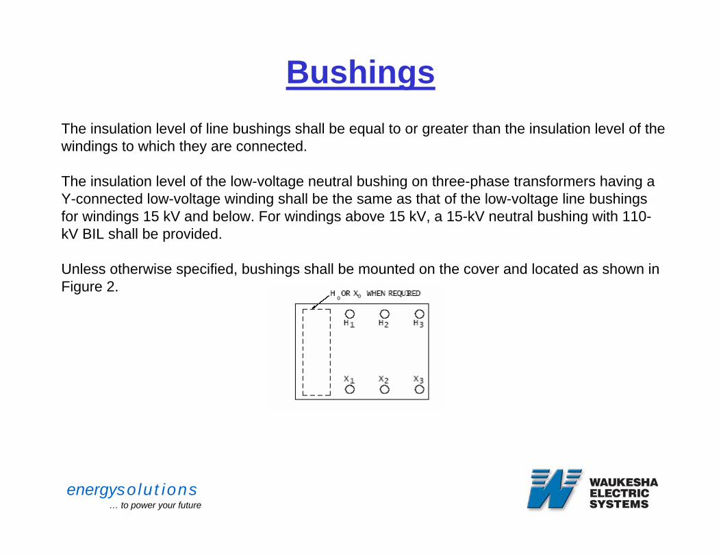
Bushings5.2 BushingsThe insulation level of line bushings shall be equal to or greater than the insulation level of the windings to which they are connected.
The insulation level of the low-voltage neutral bushing on three-phase transformers having a Y-connected low-voltage winding shall be the same as that of the low-voltage line bushings for windings 15 kV and below. For windings above 15 kV, a 15-kV neutral bushing with 110-kV BIL shall be provided.
Unless otherwise specified, bushings shall be mounted on the cover and located as shown in Figure 2.
NOTE—For single phase transformers, omit H3, X3, and neutral bushings.Figure 2 – Bushing Arrangement
energysolutions… to power your future
Oil Preservation Systems
energysolutions… to power your future
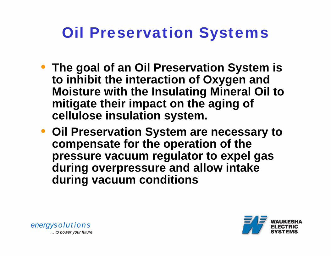
Oil Preservation Systems
• The goal of an Oil Preservation System is to inhibit the interaction of Oxygen and Moisture with the Insulating Mineral Oil to mitigate their impact on the aging of cellulose insulation system.
• Oil Preservation System are necessary to compensate for the operation of the pressure vacuum regulator to expel gas during overpressure and allow intake during vacuum conditions
energysolutions… to power your future
Oil Preservation Systems
• Factors • Load Variations• Temperature Variations• Leaks• Maintenance • Testing
energysolutions… to power your future
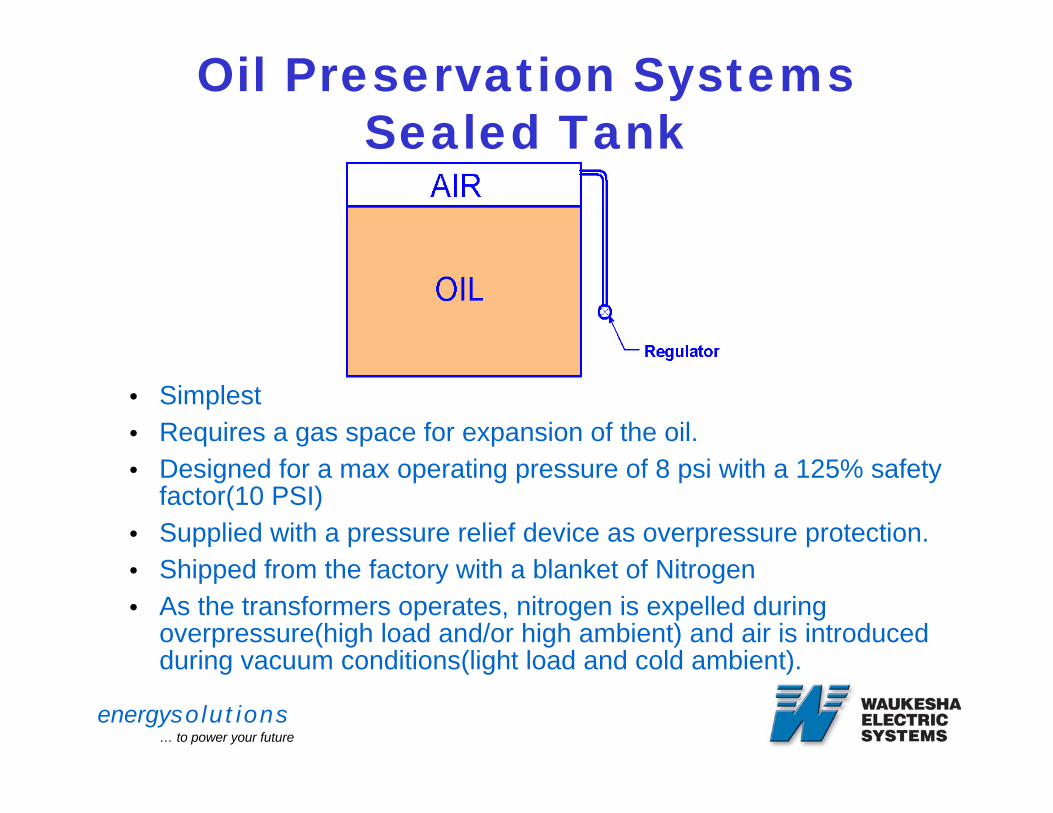
Oil Preservation SystemsSealed Tank
• Simplest • Requires a gas space for expansion of the oil.• Designed for a max operating pressure of 8 psi with a 125% safety
factor(10 PSI)• Supplied with a pressure relief device as overpressure protection.• Shipped from the factory with a blanket of Nitrogen • As the transformers operates, nitrogen is expelled during
overpressure(high load and/or high ambient) and air is introduced during vacuum conditions(light load and cold ambient).
energysolutions… to power your future
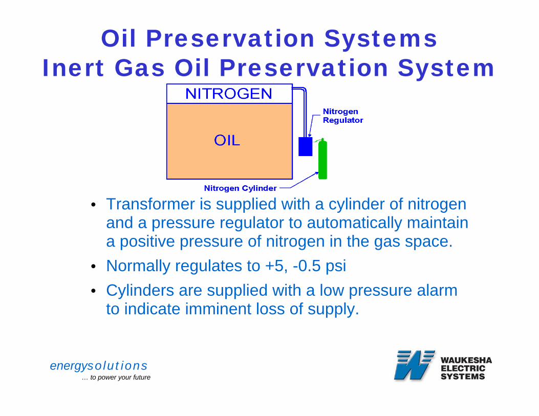
Oil Preservation SystemsInert Gas Oil Preservation System
• Transformer is supplied with a cylinder of nitrogen and a pressure regulator to automatically maintain a positive pressure of nitrogen in the gas space.
• Normally regulates to +5, -0.5 psi• Cylinders are supplied with a low pressure alarm
to indicate imminent loss of supply.
energysolutions… to power your future
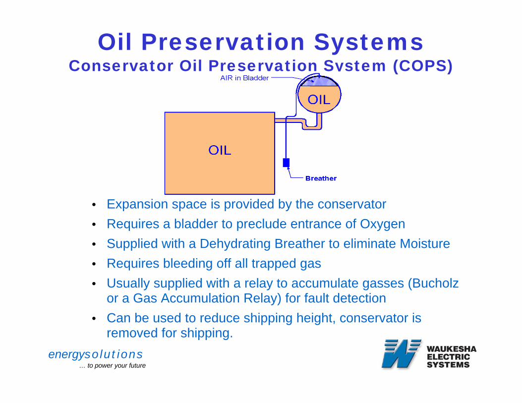
Oil Preservation SystemsConservator Oil Preservation System (COPS)
• Expansion space is provided by the conservator• Requires a bladder to preclude entrance of Oxygen• Supplied with a Dehydrating Breather to eliminate Moisture• Requires bleeding off all trapped gas• Usually supplied with a relay to accumulate gasses (Bucholz
or a Gas Accumulation Relay) for fault detection• Can be used to reduce shipping height, conservator is
removed for shipping.
energysolutions… to power your future
Tap Changers
• DETCs• Voltage Regulation Methods• Load Tap Changers• LTC Application considerations• IEEE Standard C57.131-1995
energysolutions… to power your future
Tap Changers
A device designed to allow changing the winding connections:
• DETC (De-energized)
• LTC (Energized and Under Load)
energysolutions… to power your future
DETCs
• De Energized Tap Changers
• Typically five positions, 10 % range
• Two above and two below nominal@ 2.5%
energysolutions… to power your future
DETCs
• Used to match transformer primary to actual transmission line voltage.
• Adjust turns to match design core flux density.
• Used to adjust travel of LTC mechanism.
energysolutions… to power your future
DETCs
Core performance:• Core Loss• Sound Levels
Impedance:• Inversely proportional to the square of the volts
per turn
energysolutions… to power your future
Voltage Regulation
The voltage regulation is expressed in percentage of the rated secondary voltage at full load (Normally at the ONAN rating)
energysolutions… to power your future
Voltage Regulation
Factors Affecting Voltage Regulation:
• Transmission Line variations
• Load Power Factor
• Impedance
• Load variations
energysolutions… to power your future
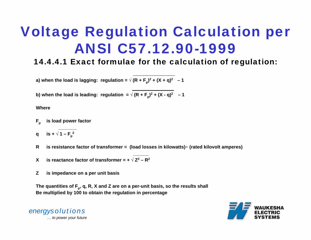
Voltage Regulation Calculation per ANSI C57.12.90-1999
14.4.4.1 Exact formulae for the calculation of regulation:____________
a) when the load is lagging: regulation = √ (R + Fp)2 + (X + q)2 – 1 ________________
b) when the load is leading: regulation = √ (R + Fp)2 + (X - q)2 – 1
Where
Fp is load power factor_______
q is + √ 1 – Fp2
R is resistance factor of transformer = (load losses in kilowatts)÷ (rated kilovolt amperes) ______
X is reactance factor of transformer = + √ Z2 – R2
Z is impedance on a per unit basis
The quantities of Fp, q, R, X and Z are on a per-unit basis, so the results shallBe multiplied by 100 to obtain the regulation in percentage
energysolutions… to power your future
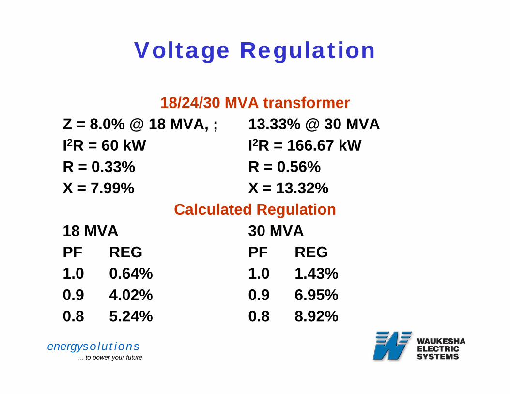
Voltage Regulation
18/24/30 MVA transformerZ = 8.0% @ 18 MVA, ; 13.33% @ 30 MVAI2R = 60 kW I2R = 166.67 kWR = 0.33% R = 0.56% X = 7.99% X = 13.32%
Calculated Regulation18 MVA 30 MVAPF REG PF REG1.0 0.64% 1.0 1.43%0.9 4.02% 0.9 6.95%0.8 5.24% 0.8 8.92%
energysolutions… to power your future
Voltage Regulation
• Regulators
• Power Factor Correction
• Load Tap Changers (LTCs)
energysolutions… to power your future
Load Tap Changers
Typical Specifications:
• 33 steps• +/- 10% (5/8% steps)• Full Capacity above nominal voltage• Rated current (reduced capacity) below nominal
voltage
energysolutions… to power your future
Load Tap Changers
• Operation at lower than rated voltages
• Extended tap ranges (+/- 15% or +20/-10%)
energysolutions… to power your future
Series ParallelTransformer Connections
energysolutions… to power your future
Series Parallel Connections
• “Two-winding” transformer may consist of more than two actual windings.
• Connect windings or sections of windings in series or parallel
• Tap out windings or sections of windings
energysolutions… to power your future
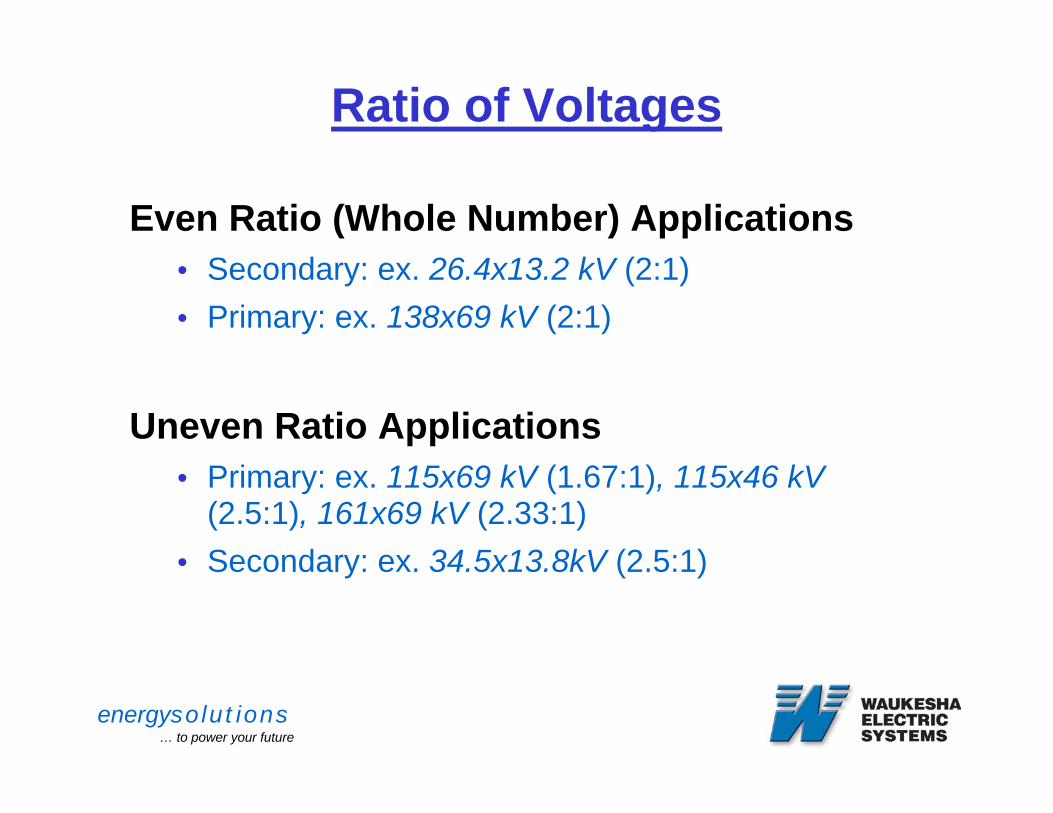
Ratio of Voltages
Even Ratio (Whole Number) Applications• Secondary: ex. 26.4x13.2 kV (2:1) • Primary: ex. 138x69 kV (2:1)
Uneven Ratio Applications• Primary: ex. 115x69 kV (1.67:1), 115x46 kV
(2.5:1), 161x69 kV (2.33:1)• Secondary: ex. 34.5x13.8kV (2.5:1)
energysolutions… to power your future
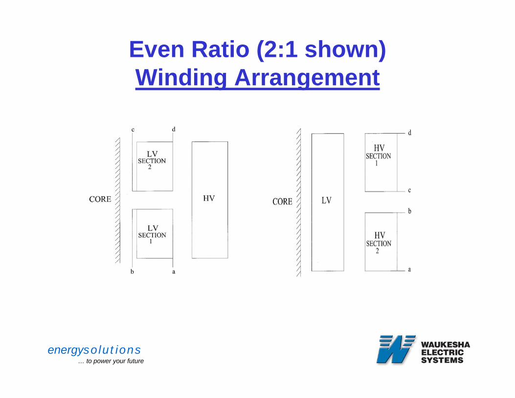
Even Ratio (2:1 shown)Winding Arrangement
Secondary Primary
Winding designed in two sections and stacked in axial arrangement.
energysolutions… to power your future
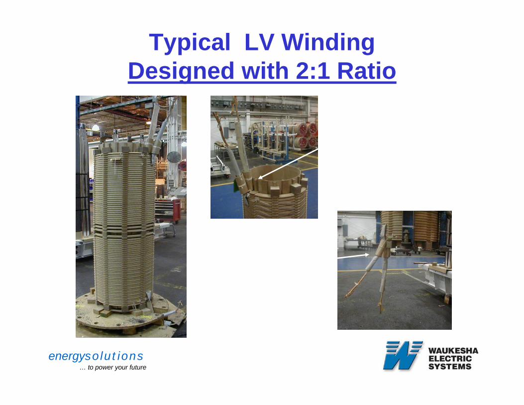
Typical LV WindingDesigned with 2:1 Ratio
Leads c & d exiting from top of coil
Leads a & b exiting from top of coil
energysolutions… to power your future
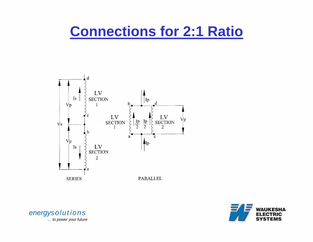
Connections for 2:1 Ratio
Vs = Series Voltage
Vp = Parallel Voltage
Is = Series Current
Ip = Parallel Current

energysolutions… to power your future
Even Ratio ApplicationsPerformance Characteristics
• No significant differences in main performance characteristics between two connections
• Load losses, impedance, no-load losses, and sound level remain constant
• Resistance will be different due to windings being connected in series or parallel.
energysolutions… to power your future
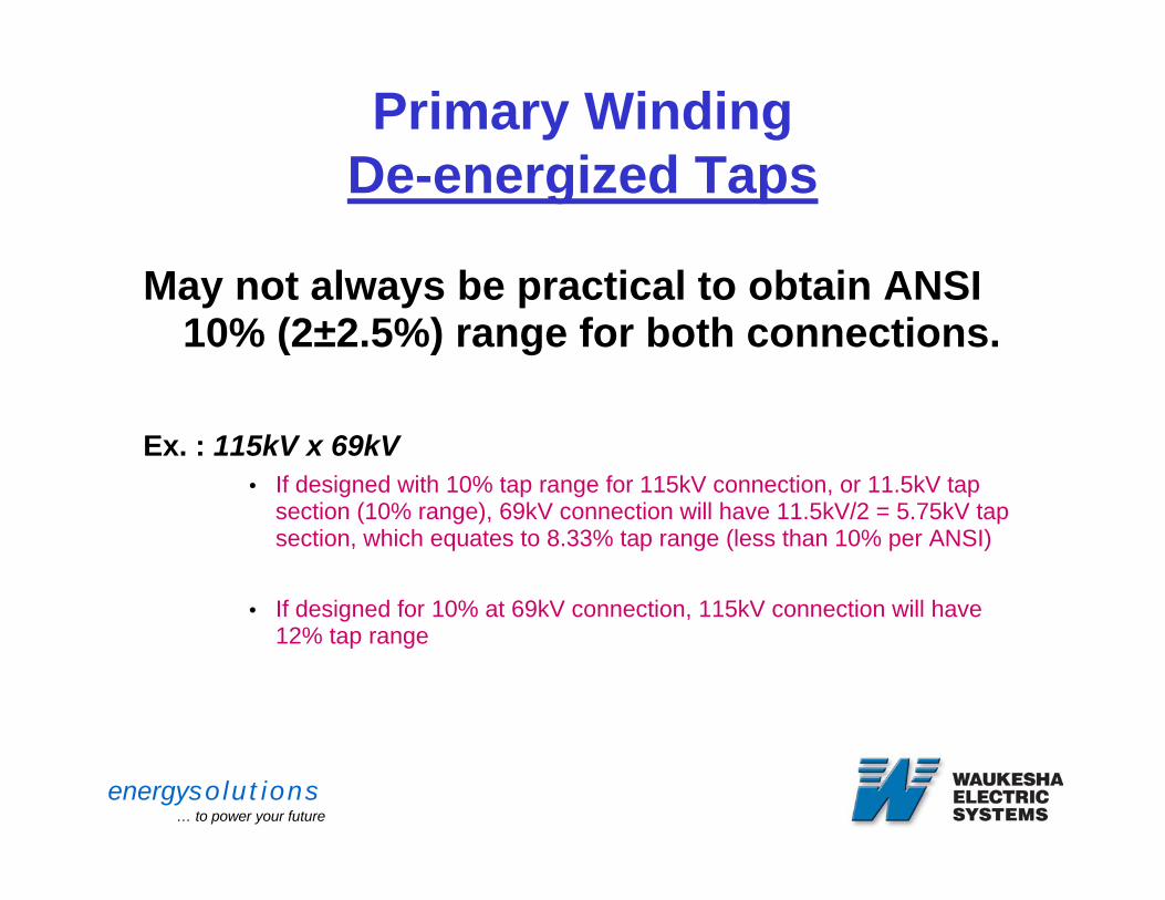
Primary WindingDe-energized Taps
May not always be practical to obtain ANSI 10% (2±2.5%) range for both connections.
Ex. : 115kV x 69kV• If designed with 10% tap range for 115kV connection, or 11.5kV tap
section (10% range), 69kV connection will have 11.5kV/2 = 5.75kV tap section, which equates to 8.33% tap range (less than 10% per ANSI)
• If designed for 10% at 69kV connection, 115kV connection will have 12% tap range
energysolutions… to power your future
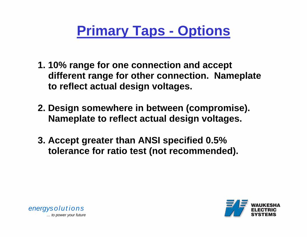
Primary Taps - Options
1. 10% range for one connection and accept different range for other connection. Nameplate to reflect actual design voltages.
2. Design somewhere in between (compromise). Nameplate to reflect actual design voltages.
3. Accept greater than ANSI specified 0.5% tolerance for ratio test (not recommended).
energysolutions… to power your future
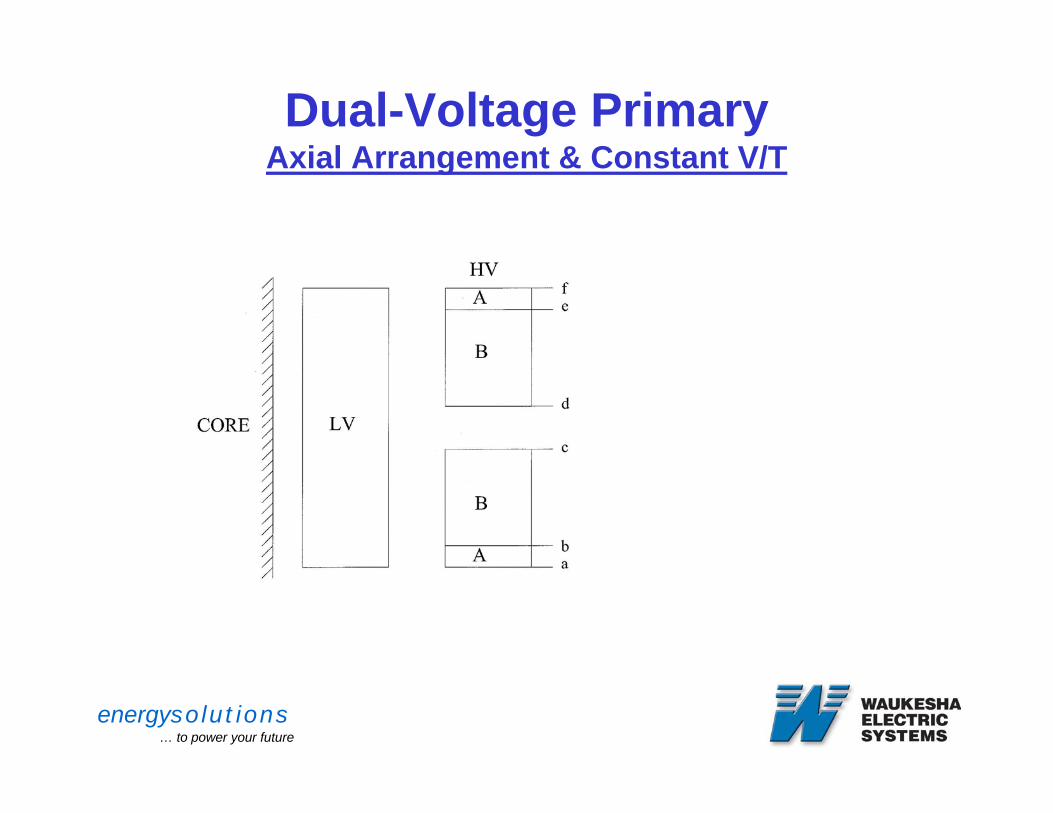
Dual-Voltage PrimaryAxial Arrangement & Constant V/T
•Primary winding consists of multiple sections.
•Connections depend upon actual ratio specified.
energysolutions… to power your future
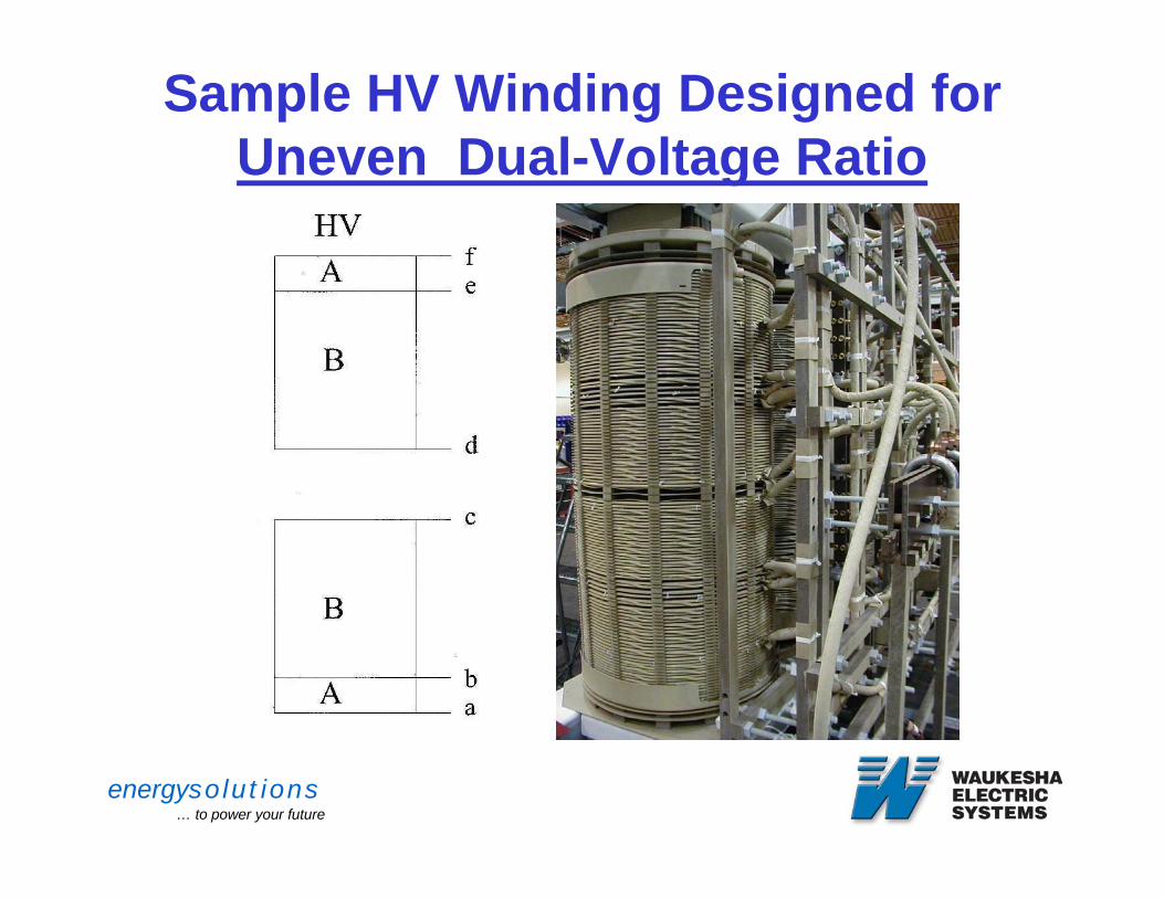
Sample HV Winding Designed for Uneven Dual-Voltage Ratio
energysolutions… to power your future
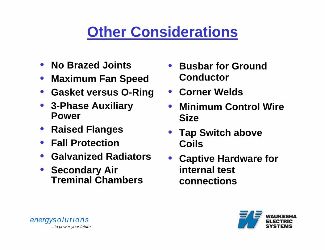
Other Considerations
• No Brazed Joints• Maximum Fan Speed• Gasket versus O-Ring• 3-Phase Auxiliary
Power• Raised Flanges• Fall Protection• Galvanized Radiators• Secondary Air
Treminal Chambers
• Busbar for Ground Conductor
• Corner Welds• Minimum Control Wire
Size• Tap Switch above
Coils• Captive Hardware for
internal test connections
energysolutions… to power your future
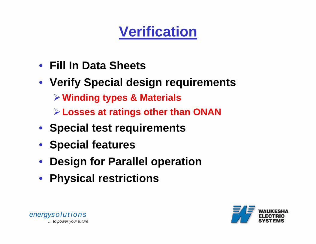
Verification
• Fill In Data Sheets• Verify Special design requirements
Winding types & MaterialsLosses at ratings other than ONAN
• Special test requirements• Special features• Design for Parallel operation• Physical restrictions
energysolutions… to power your future
Desired Result
• Supplier understands and fulfills the specification
• Purchaser has no surprises:Approval DrawingsTestingDelivery & Installation
energysolutions… to power your future
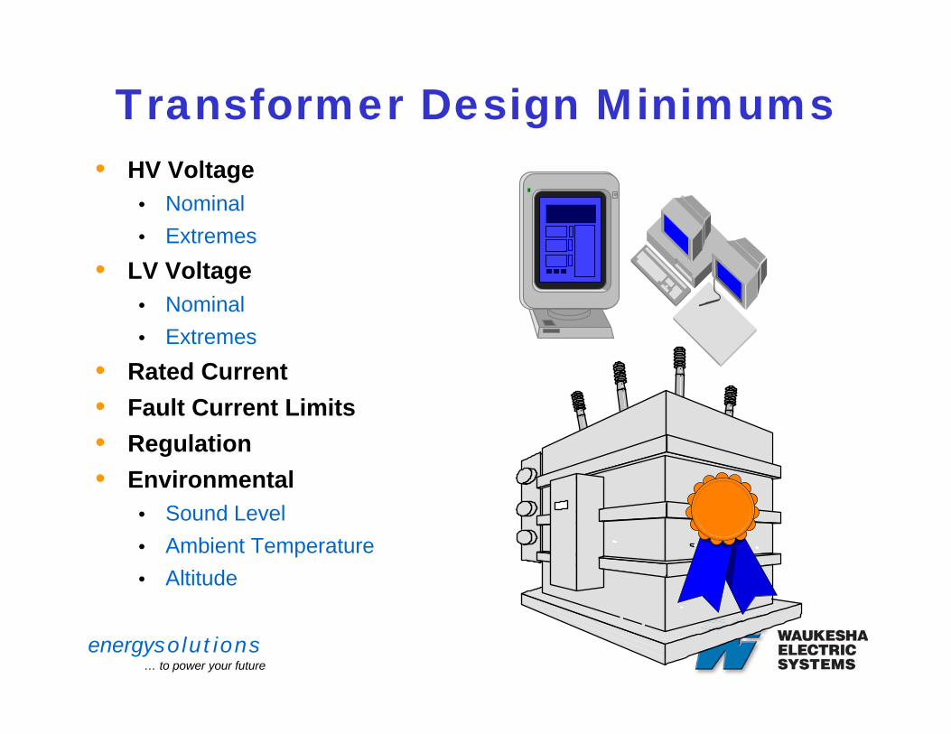
Transformer Design Minimums• HV Voltage
• Nominal • Extremes
• LV Voltage• Nominal • Extremes
• Rated Current• Fault Current Limits• Regulation• Environmental
• Sound Level• Ambient Temperature• Altitude
energysolutions… to power your future
Factory Testing
energysolutions… to power your future
REASONS FOR TESTING
COMPLIANCE WITH CUSTOMER SPECIFICATIONS
ASSESSMENT OF QUALITY ANDRELIABILITY
VERIFICATION OF DESIGN
COMPLIANCE WITH INDUSTRY STANDARDS
energysolutions… to power your future
IEEE and ANSI STANDARDS
PRECISE COMMUNICATIONS
IDENTIFICATION OF CRITICAL FEATURES
SIMPLER CONTRACTUAL RELATIONSHIP
MINIMUM PERFORMANCE REQUIREMENTS FOR SAFETY
VALUABLE SOURCE OF TECHNICAL INFORMATION
energysolutions… to power your future
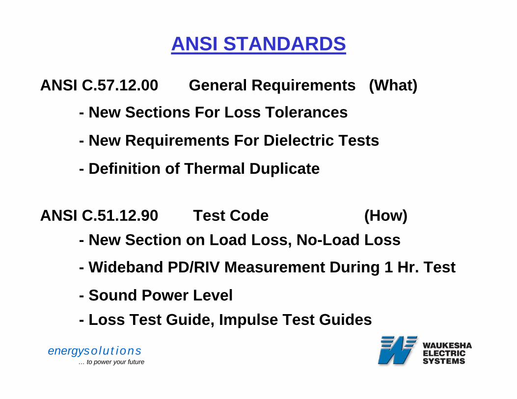
ANSI STANDARDS
ANSI C.57.12.00 General Requirements (What)- New Sections For Loss Tolerances
- New Requirements For Dielectric Tests
- Definition of Thermal Duplicate
ANSI C.51.12.90 Test Code (How)- New Section on Load Loss, No-Load Loss
- Wideband PD/RIV Measurement During 1 Hr. Test
- Sound Power Level- Loss Test Guide, Impulse Test Guides

energysolutions… to power your future
ROUTINE TESTS
BEFORE TANKING
* CORE INSULATION TESTS
* PRE-LEAD ASSEMBLY RATIO TESTS AND ELECTRICAL CENTRE MEASUREMENTS
* PRE-VAPOR PHASE RATIO TEST
* BUSHING CURRENT TRANSFORMER RATIO AND POLARITY TEST
energysolutions… to power your future
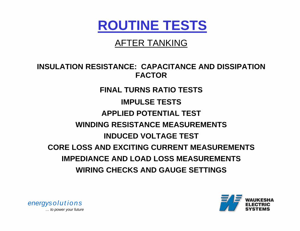
ROUTINE TESTSAFTER TANKING
INSULATION RESISTANCE: CAPACITANCE AND DISSIPATION FACTOR
FINAL TURNS RATIO TESTSIMPULSE TESTS
APPLIED POTENTIAL TESTWINDING RESISTANCE MEASUREMENTS
INDUCED VOLTAGE TESTCORE LOSS AND EXCITING CURRENT MEASUREMENTS
IMPEDIANCE AND LOAD LOSS MEASUREMENTS WIRING CHECKS AND GAUGE SETTINGS
energysolutions… to power your future
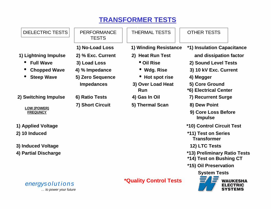
TRANSFORMER TESTS
DIELECTRIC TESTS PERFORMANCETESTS
THERMAL TESTS OTHER TESTS
TRANSIENTS1) No-Load Loss 1) Winding Resistance *1) Insulation Capacitance
1) Lightning Impulse 2) % Exc. Current 2) Heat Run Test and dissipation factori Full Wave 3) Load Loss iOil Rise 2) Sound Level Testsi Chopped Wave 4) % Impedance iWdg. Rise 3) 10 kV Exc. Currenti Steep Wave 5) Zero Sequence i Hot spot rise 4) Megger
Impedances 3) Over Load Heat 5) Core Ground Run *6) Electrical Center
2) Switching Impulse 6) Ratio Tests 4) Gas In Oil 7) Recurrent Surge7) Short Circuit 5) Thermal Scan 8) Dew Point
9) Core Loss Before Impulse
1) Applied Voltage *10) Control Circuit Test2) 10 Induced *11) Test on Series
Transformer3) Induced Voltage 12) LTC Tests4) Partial Discharge *13) Preliminary Ratio Tests
*14) Test on Bushing CT *15) Oil Preservation
System Tests*Quality Control Tests
LOW (POWER) FREQUNCY
energysolutions… to power your future
DIELECTRIC TESTS
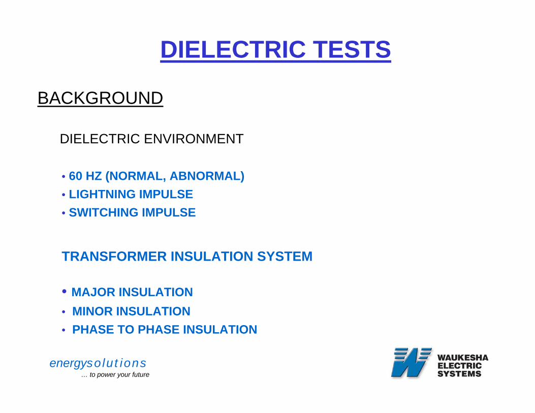
BACKGROUND
DIELECTRIC ENVIRONMENT
• 60 HZ (NORMAL, ABNORMAL)• LIGHTNING IMPULSE• SWITCHING IMPULSE
TRANSFORMER INSULATION SYSTEM
• MAJOR INSULATION• MINOR INSULATION• PHASE TO PHASE INSULATION
energysolutions… to power your future
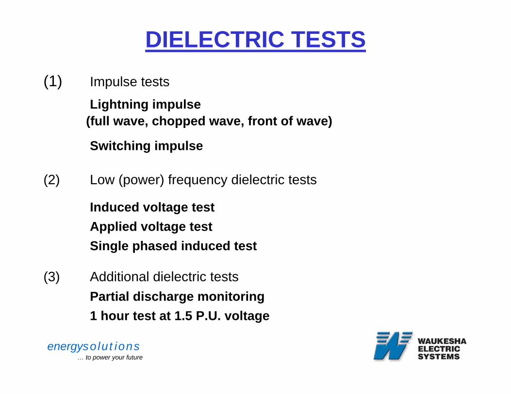
DIELECTRIC TESTS(1) Impulse tests
Lightning impulse(full wave, chopped wave, front of wave)
Switching impulse
(2) Low (power) frequency dielectric tests
Induced voltage testApplied voltage testSingle phased induced test
(3) Additional dielectric testsPartial discharge monitoring1 hour test at 1.5 P.U. voltage
energysolutions… to power your future
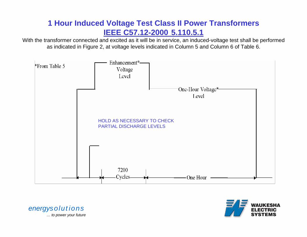
1 Hour Induced Voltage Test Class II Power Transformers IEEE C57.12-2000 5.110.5.1
With the transformer connected and excited as it will be in service, an induced-voltage test shall be performedas indicated in Figure 2, at voltage levels indicated in Column 5 and Column 6 of Table 6.
HOLD AS NECESSARY TO CHECK PARTIAL DISCHARGE LEVELS
energysolutions… to power your future
Failure Detection
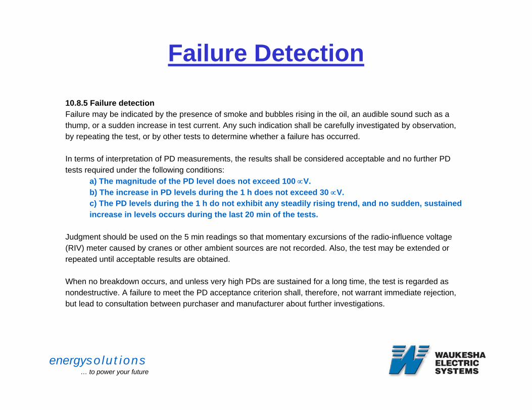
10.8.5 Failure detectionFailure may be indicated by the presence of smoke and bubbles rising in the oil, an audible sound such as athump, or a sudden increase in test current. Any such indication shall be carefully investigated by observation,by repeating the test, or by other tests to determine whether a failure has occurred.
In terms of interpretation of PD measurements, the results shall be considered acceptable and no further PDtests required under the following conditions:
a) The magnitude of the PD level does not exceed 100 ∝V.b) The increase in PD levels during the 1 h does not exceed 30 ∝V.c) The PD levels during the 1 h do not exhibit any steadily rising trend, and no sudden, sustainedincrease in levels occurs during the last 20 min of the tests.
Judgment should be used on the 5 min readings so that momentary excursions of the radio-influence voltage(RIV) meter caused by cranes or other ambient sources are not recorded. Also, the test may be extended orrepeated until acceptable results are obtained.
When no breakdown occurs, and unless very high PDs are sustained for a long time, the test is regarded asnondestructive. A failure to meet the PD acceptance criterion shall, therefore, not warrant immediate rejection,but lead to consultation between purchaser and manufacturer about further investigations.
energysolutions… to power your future
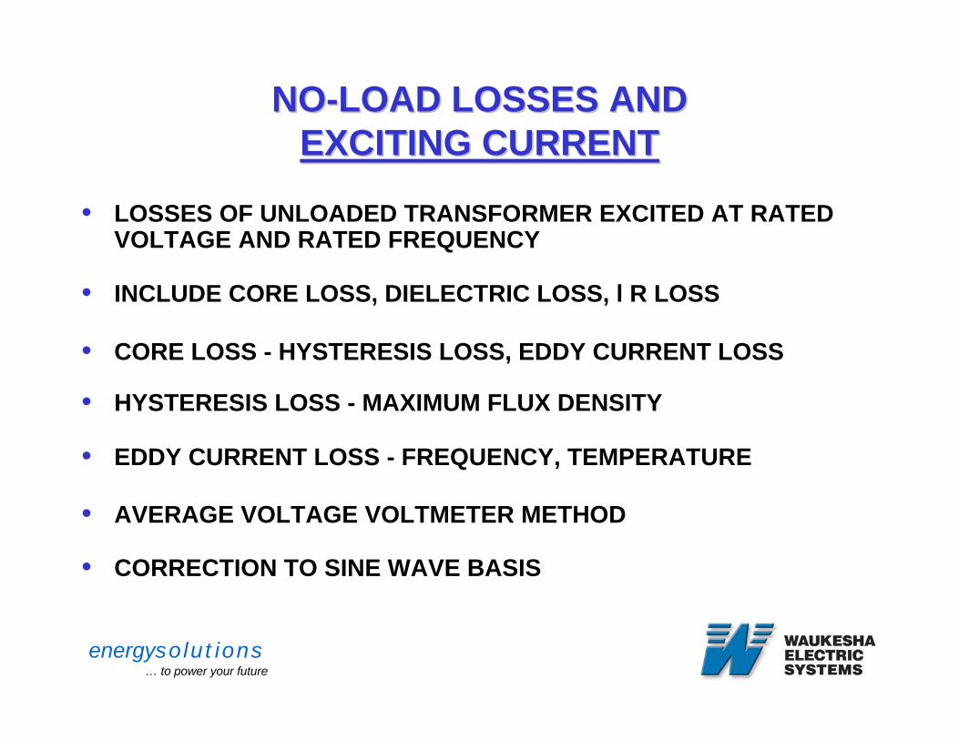
NONO--LOAD LOSSES ANDLOAD LOSSES ANDEXCITING CURRENTEXCITING CURRENT
• LOSSES OF UNLOADED TRANSFORMER EXCITED AT RATED VOLTAGE AND RATED FREQUENCY
• INCLUDE CORE LOSS, DIELECTRIC LOSS, l R LOSS
• CORE LOSS - HYSTERESIS LOSS, EDDY CURRENT LOSS
• HYSTERESIS LOSS - MAXIMUM FLUX DENSITY
• EDDY CURRENT LOSS - FREQUENCY, TEMPERATURE
• AVERAGE VOLTAGE VOLTMETER METHOD
• CORRECTION TO SINE WAVE BASIS
2
energysolutions… to power your future
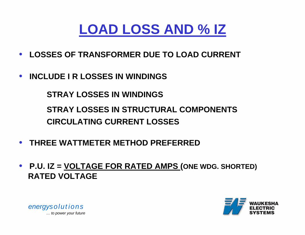
LOAD LOSS AND % IZ• LOSSES OF TRANSFORMER DUE TO LOAD CURRENT
• INCLUDE I R LOSSES IN WINDINGS
STRAY LOSSES IN WINDINGS
STRAY LOSSES IN STRUCTURAL COMPONENTSCIRCULATING CURRENT LOSSES
• THREE WATTMETER METHOD PREFERRED
• P.U. IZ = VOLTAGE FOR RATED AMPS (ONE WDG. SHORTED)RATED VOLTAGE
2
energysolutions… to power your future
THERMAL TESTS
MEASUREMENTS OF WINDING RESISTANCES
TEMPERATURE RISE TEST
OVER LOAD HEAT RUNS
GAS IN OIL ANALYSIS
THERMAL SCANNING
energysolutions… to power your future
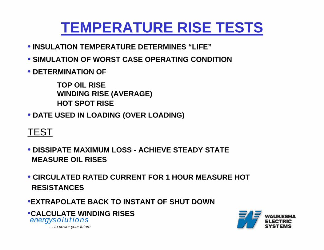
TEMPERATURE RISE TESTS• INSULATION TEMPERATURE DETERMINES “LIFE”• SIMULATION OF WORST CASE OPERATING CONDITION• DETERMINATION OF
TOP OIL RISEWINDING RISE (AVERAGE)HOT SPOT RISE
• DATE USED IN LOADING (OVER LOADING)
TEST
• DISSIPATE MAXIMUM LOSS - ACHIEVE STEADY STATE MEASURE OIL RISES
• CIRCULATED RATED CURRENT FOR 1 HOUR MEASURE HOT RESISTANCES
•EXTRAPOLATE BACK TO INSTANT OF SHUT DOWN•CALCULATE WINDING RISES
energysolutions… to power your future
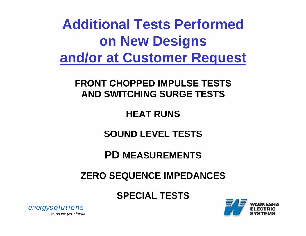
Additional Tests Performedon New Designs
and/or at Customer RequestFRONT CHOPPED IMPULSE TESTS
AND SWITCHING SURGE TESTS
HEAT RUNS
SOUND LEVEL TESTS
PD MEASUREMENTS
ZERO SEQUENCE IMPEDANCES
SPECIAL TESTS
energysolutions… to power your future
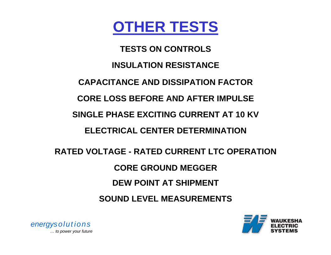
OTHER TESTSTESTS ON CONTROLS
INSULATION RESISTANCE
CAPACITANCE AND DISSIPATION FACTOR
CORE LOSS BEFORE AND AFTER IMPULSE
SINGLE PHASE EXCITING CURRENT AT 10 KV
ELECTRICAL CENTER DETERMINATION
RATED VOLTAGE - RATED CURRENT LTC OPERATION
CORE GROUND MEGGER
DEW POINT AT SHIPMENT
SOUND LEVEL MEASUREMENTS
energysolutions… to power your future
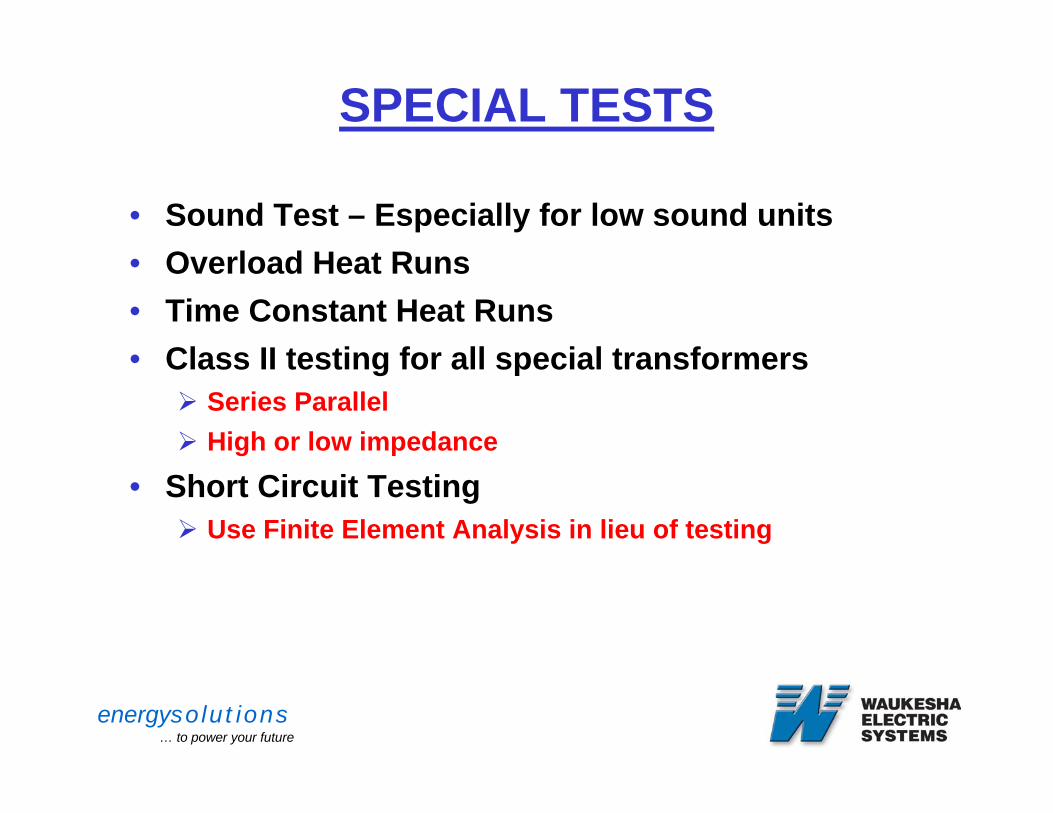
SPECIAL TESTS
• Sound Test – Especially for low sound units• Overload Heat Runs • Time Constant Heat Runs• Class II testing for all special transformers
Series ParallelHigh or low impedance
• Short Circuit Testing Use Finite Element Analysis in lieu of testing
energysolutions… to power your future
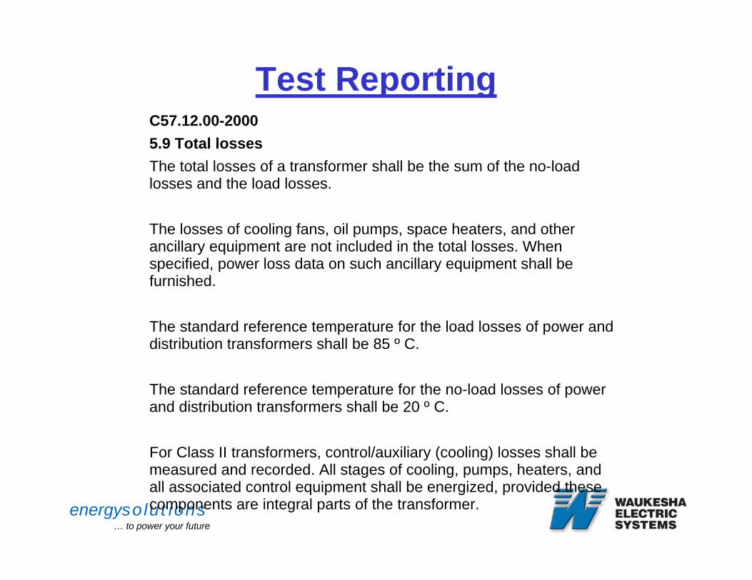
Test ReportingC57.12.00-2000 5.9 Total lossesThe total losses of a transformer shall be the sum of the no-load losses and the load losses.
The losses of cooling fans, oil pumps, space heaters, and other ancillary equipment are not included in the total losses. When specified, power loss data on such ancillary equipment shall be furnished.
The standard reference temperature for the load losses of power and distribution transformers shall be 85 º C.
The standard reference temperature for the no-load losses of power and distribution transformers shall be 20 º C.
For Class II transformers, control/auxiliary (cooling) losses shall be measured and recorded. All stages of cooling, pumps, heaters, and all associated control equipment shall be energized, provided these components are integral parts of the transformer.
energysolutions… to power your future
TRANSFORMER MONITORING
energysolutions… to power your future
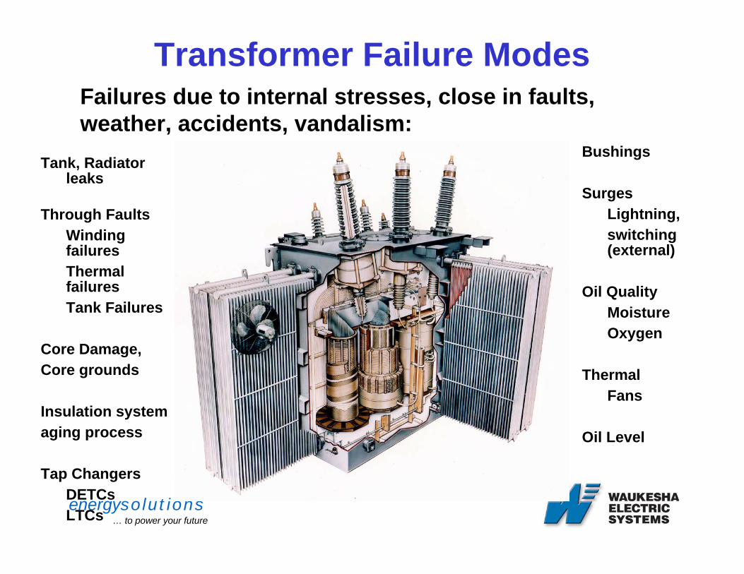
Transformer Failure Modes
Tank, Radiator leaks
Through FaultsWinding failuresThermal failuresTank Failures
Core Damage, Core grounds
Insulation systemaging process
Tap ChangersDETCsLTCs
Bushings
SurgesLightning, switching (external)
Oil QualityMoistureOxygen
Thermal Fans
Oil Level
Failures due to internal stresses, close in faults, weather, accidents, vandalism:
energysolutions… to power your future
Monitoring - Mechanical Failures
• Failures due to internal stresses, close in faults, weather, accidents, vandalism:• Tank and Radiator Failure• Winding Failures (Buckling, Tipping, Beam
bending, Telescoping, etc.)• Core Damage• Insulation Damage• Lead Faults• Bushing Mechanical Failure
energysolutions… to power your future
Transformer MonitoringElectrical Failures
• Failure initially categorized into areas such as over voltage or partial discharge exceeding the withstand strength of the insulation system
• Failures as a result of:• Switching surges• Lightning • Synchronism issues
• Typically accompanied by Thermal or Chemical failure
• Loss of Insulating oil below critical oil level
energysolutions… to power your future
Transformer MonitoringThermal
• Failure due to insulation or conductor destruction as a result of:• Short or long term overloading• Faults• Undersized leads• Contact coking• Bad joints• Loss of cooling• Design issues• Low oil levels
energysolutions… to power your future
Transformer MonitoringChemical
• Failure due toThe ingress of water or oxygenLoss of insulating oilPaper degradation due to thermal issues or aging
Less obvious, Most overlooked
Increases potential of the other three failure modes
Paper insulation deteriorates from the effects of moisture, oxygen, and temperature and time.
Moisture and oxygen are controlled by the maintenance practices while the rate of thermal degradation is controlled by loading practices.
Failure of the oil preservation system.
energysolutions… to power your future
Transformer MonitoringFailure Mode Analysis
• FMA provides what, when, and how to monitor• Many tests require transformer to be de-
energized• Monitoring provides detection and direction for
further prevention testing• Many tests require transformer to be de-energized• Current operating practices prevent typical testing
procedures due to limited outages• ONLINE MONITORING, A VIABLE SOLUTION TO
PROVIDE PREDICTION OF TRANSFORMER FAILURES AND ALLOW INTERVENTION BEFORE FAILURE
energysolutions… to power your future
Liquid Level
• Oil Level monitoring• Alarm to allow intervention• Trip to provide protection• Leak• Critical Oil Level trip to prevent dielectric failure• Low oil levels resulting from sampling losses,
especially in LTCs where oil volumes are significantly smaller
• Low oil level below radiator headers result in thermal failure
energysolutions… to power your future
Transformer MonitoringOn Line Chemical Detection
• Chemical Detection through On Line Gas & Oil Monitors
• Most significant• Majority of all utilities use DGA
• Manually sample 1-4 times/year• Oil quality yearly or less• Problems causing failure can go out of control
between manual sampling schedule
energysolutions… to power your future
Transformer MonitoringDGA
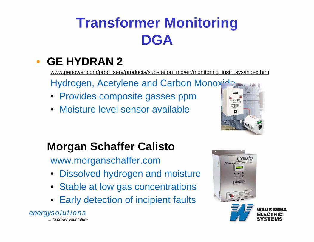
• GE HYDRAN 2 www.gepower.com/prod_serv/products/substation_md/en/monitoring_instr_sys/index.htm
Hydrogen, Acetylene and Carbon Monoxide• Provides composite gasses ppm• Moisture level sensor available
Morgan Schaffer Calistowww.morganschaffer.com• Dissolved hydrogen and moisture• Stable at low gas concentrations• Early detection of incipient faults
energysolutions… to power your future
Transformer MonitoringDGA
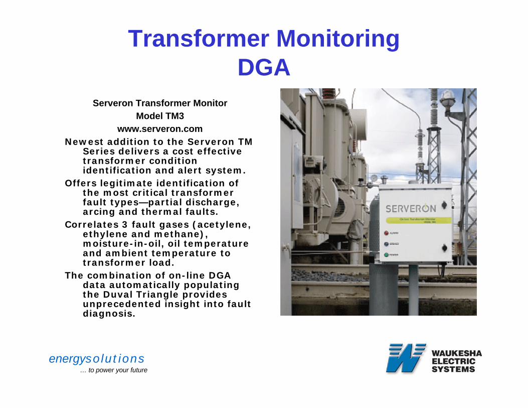
Serveron Transformer MonitorModel TM3
www.serveron.comNewest addition to the Serveron TM
Series delivers a cost effective transformer condition identification and alert system.
Offers legitimate identification of the most critical transformer fault types—partial discharge, arcing and thermal faults.
Correlates 3 fault gases (acetylene, ethylene and methane), moisture-in-oil, oil temperature and ambient temperature to transformer load.
The combination of on-line DGA data automatically populating the Duval Triangle provides unprecedented insight into fault diagnosis.
energysolutions… to power your future
Transformer Monitoring DGA
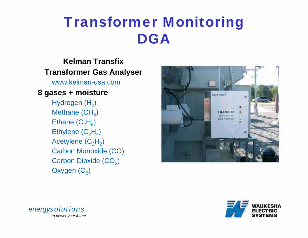
Kelman Transfix Transformer Gas Analyser
www.kelman-usa.com8 gases + moisture
Hydrogen (H2)Methane (CH4)Ethane (C2H6)Ethylene (C2H4) Acetylene (C2H2)Carbon Monoxide (CO)Carbon Dioxide (CO2)Oxygen (O2)
energysolutions… to power your future
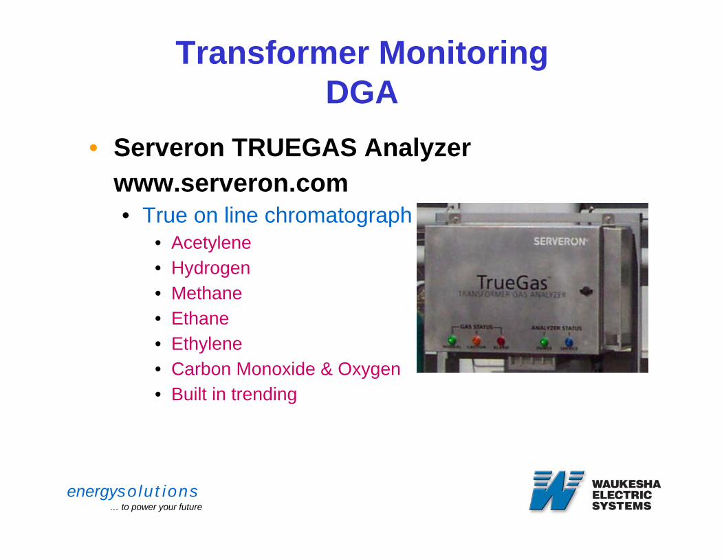
Transformer MonitoringDGA
• Serveron TRUEGAS Analyzerwww.serveron.com• True on line chromatograph monitor:
• Acetylene• Hydrogen• Methane• Ethane• Ethylene• Carbon Monoxide & Oxygen• Built in trending
energysolutions… to power your future
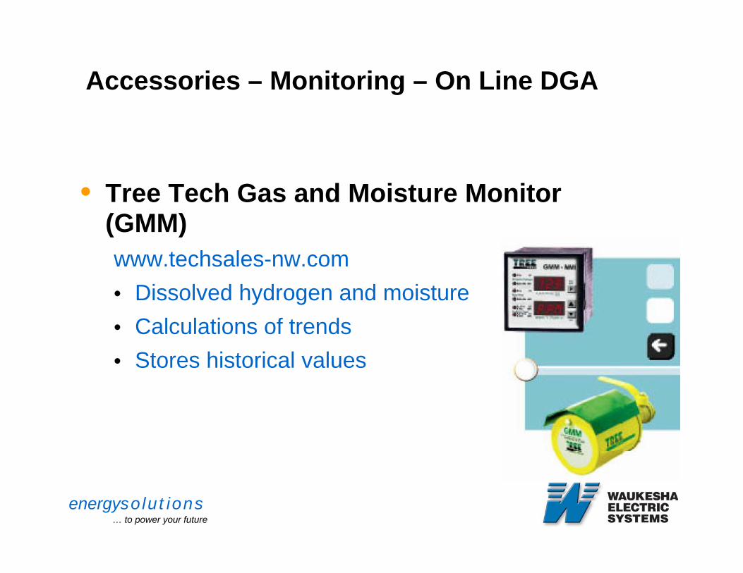
Accessories – Monitoring – On Line DGA
• Tree Tech Gas and Moisture Monitor (GMM)www.techsales-nw.com• Dissolved hydrogen and moisture• Calculations of trends• Stores historical values
energysolutions… to power your future
Transformer MonitoringTemperature Detection
• Thermal Detection Equipment• Top Oil• Hot Spot• LTC Oil Temperature• LTC – Main Tank differential
• Mechanical equipment only provides maximum, duration is also critical
energysolutions… to power your future
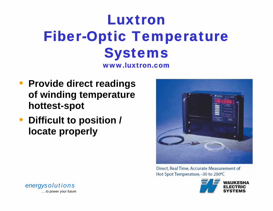
Luxtron Fiber-Optic Temperature
Systemswww.luxtron.com
• Provide direct readings of winding temperature hottest-spot
• Difficult to position / locate properly
energysolutions… to power your future
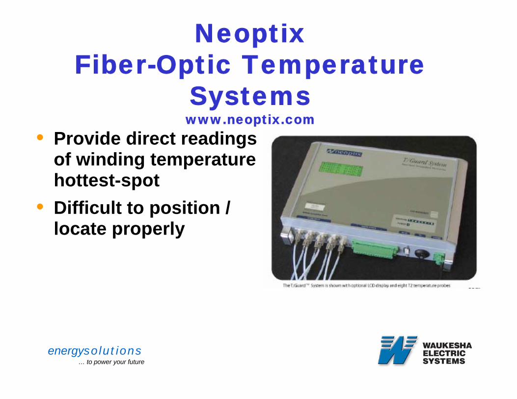
Neoptix Fiber-Optic Temperature
Systemswww.neoptix.com
• Provide direct readings of winding temperature hottest-spot
• Difficult to position / locate properly
energysolutions… to power your future
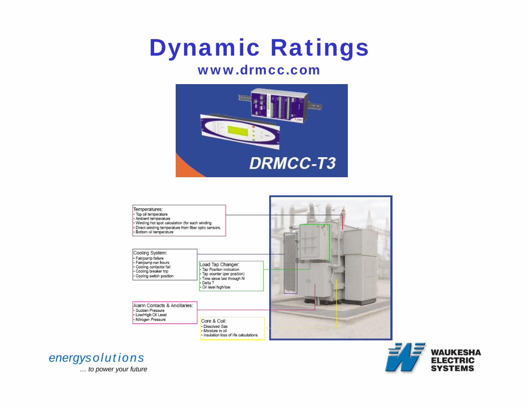
Dynamic Ratingswww.drmcc.com
energysolutions… to power your future
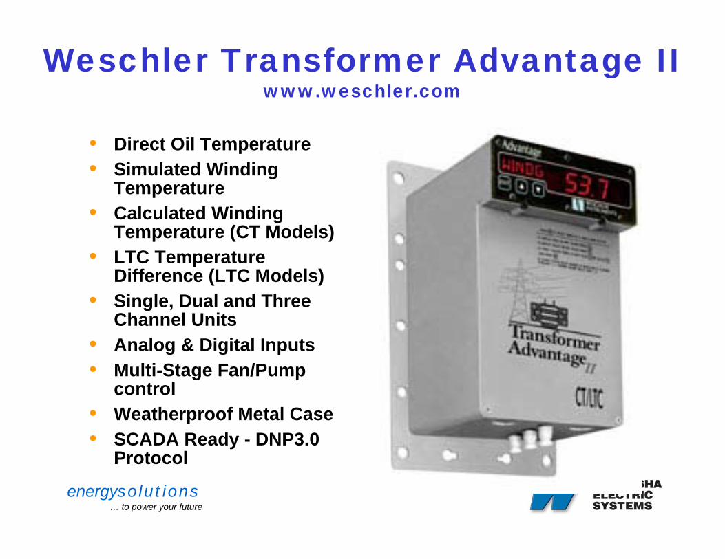
Weschler Transformer Advantage IIwww.weschler.com
• Direct Oil Temperature • Simulated Winding
Temperature • Calculated Winding
Temperature (CT Models) • LTC Temperature
Difference (LTC Models) • Single, Dual and Three
Channel Units • Analog & Digital Inputs• Multi-Stage Fan/Pump
control • Weatherproof Metal Case • SCADA Ready - DNP3.0
Protocol
energysolutions… to power your future
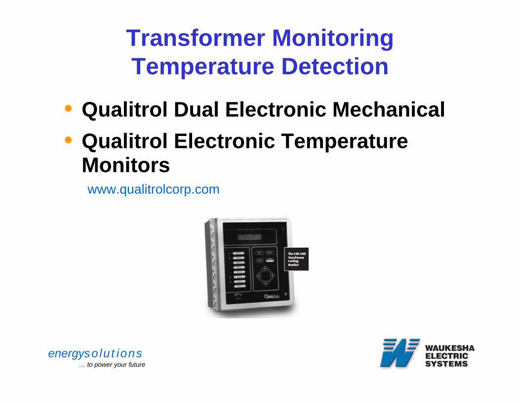
Transformer MonitoringTemperature Detection
• Qualitrol Dual Electronic Mechanical • Qualitrol Electronic Temperature
Monitorswww.qualitrolcorp.com
energysolutions… to power your future
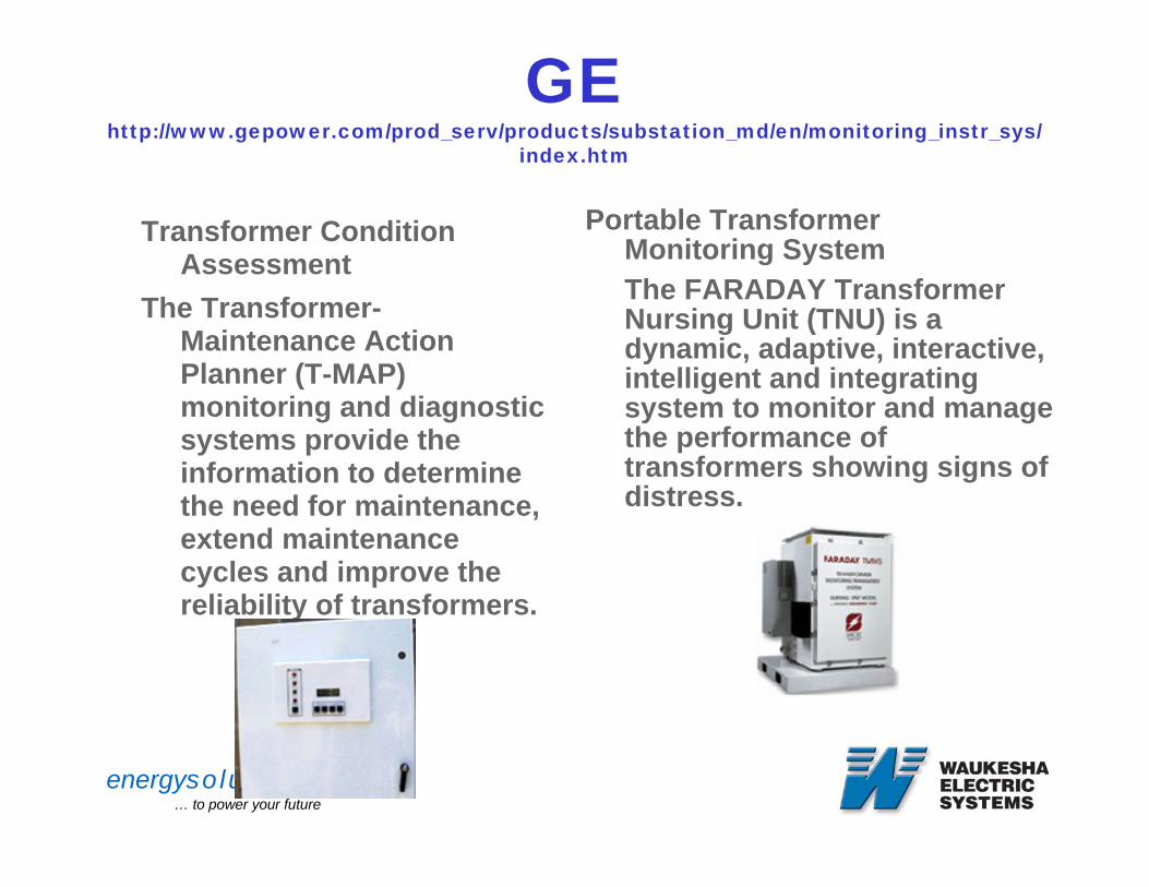
GEhttp://www.gepower.com/prod_serv/products/substation_md/en/monitoring_instr_sys/
index.htm
Transformer Condition Assessment
The Transformer-Maintenance Action Planner (T-MAP) monitoring and diagnostic systems provide the information to determine the need for maintenance, extend maintenance cycles and improve the reliability of transformers.
Portable TransformerMonitoring SystemThe FARADAY Transformer Nursing Unit (TNU) is a dynamic, adaptive, interactive, intelligent and integrating system to monitor and manage the performance of transformers showing signs of distress.
energysolutions… to power your future
TRANSFORMER MONITORING
• DOBLE www.doble.com/products/continuous_online_diagnostics.html
• SCHWEITZER www.selinc.com/sel-701-1.htm
• BECKWITH ELECTRIC• ORTO (www.ortodemexico.com)
energysolutions… to power your future
Transformer MonitoringMechanical
• Sudden Pressure/Fault Pressure RPRR relays
• Mechanical Pressure Relief Device• Liquid Level• Pressure Vacuum • Gas Accumulation Relay• Oil Flow monitor
energysolutions… to power your future
Transformer MonitoringOther Considerations
• Bushings• Acoustic detection of partial discharges• Fan, Pumps operating currents• LTCs
• Motor Operating time• # of operations• Prediction of contact life • Position indication• Travel limits (16R or 16L)• Oil DGA monitoring
energysolutions… to power your future
Transformer MonitoringConclusions
• Use of Electronic and electromechanical monitors reduce need for on site inspection
• Monitoring only effective as a predictor, does not replace required maintenance
• Only valuable if information is in useable form• Notification of significant indicators• User’s need to determine what is significant
• USER needs comfort with reliability,
energysolutions… to power your future
Transformer MonitoringConclusions
• Many systems currently on the market and being developed
• Systems range from simple to complex• Failure detection rate needs to be
evaluated before purchase• Failures can occur between • Monitors of no value if data cannot be
retrieved easily